Article

Experimental Study on Cooling Performance of a Hybrid Microchannel and Jet Impingement Heat Sink

1
State Key Laboratory of Multiphase Flow in Power Engineering, Xi’an Jiaotong University, Xi’an 710049, China
2
Key Laboratory of Icing and Anti/De-Icing, China Aerodynamics Research and Development Center, Mianyang 621000, China
*
Author to whom correspondence should be addressed.
Appl. Sci. 2022, 12(24), 13033; https://doi.org/10.3390/app122413033
Submission received: 16 November 2022 / Revised: 13 December 2022 / Accepted: 16 December 2022 / Published: 19 December 2022
(This article belongs to the Topic Applied Heat Transfer)

Abstract

:
Thermal management at a high heat flux is crucial for high-power electronic devices, and jet impingement cooling is a promising solution. In this paper, a hybrid heat sink combining a microchannel and jet impingement was designed, fabricated and tested in a closed-loop system with R134a as the working fluid. The thermal contact resistance was measured by using the steady-state method, and the thermal resistance of the heat sink was obtained at different heat fluxes and flow rates. The maximum heat dissipation of 400 W/cm2 is achieved on a heater area of 210 mm2, and the thermal resistance of the heat sink is 0.11 K/W with a pressure drop of 13.5 kPa under a flow rate of 1.90 L/min. Low thermal resistance can be achieved for the hybrid heat sink stemming from the highly-dense micro-jet array with separate inflow and outflow microchannels.

1. Introduction

High-power lasers have attracted extensive attention with the development of laser technology. A high-power diode array (HPLDA) is an effective way to convert electronic energy into a laser beam [1]. The temperature of HPLDAs affects their efficiency and reliability, and the cooling of HPLDAs is still a challenge.
Microchannel heat sink (MCH) is an effective approach for high heat flux applications [2]. Compared with macrochannel heat sinks, microchannel heat sinks have a better cooling performance and a compact structure [3]. Tuckerman and Pease [4] tested microchannel heat sinks for cooling electronic devices in 1980, which showed a cooling capacity of 750 W/cm2. Water-cooled microchannel heat sinks were designed and tested by Kreutz et al. where they cooled diode lasers with a thermal resistance of 0.29 K/W [5]. Compared with single-phase cooling, the flow boiling heat transfer can achieve cooling with a higher heat flux and more uniform temperature on the heating surface. However, there are issues of premature critical heat flux (CHF) and heat transfer deterioration owing to various instabilities in microchannels [6]. Major attention has been paid to the characteristics of instability and its suppression methods. Geometrical modification is an effective method to suppress stability [7]. In addition to flow instability, bubble clogging and flow reversal are also great challenges with microchannel heat sinks [8,9]. The effects of inlet restrictors (IRs) on heat transfer characteristics were analyzed by Saad et al. [10]. Results showed that IRs improved heat transfer characteristics effectively.
A prototype of the copper heat sink with micro-pipes in the microchannel was designed by Anna et al. [11], and a smaller dimension in the direction perpendicular to the junction was proposed to improve operability in that direction. Kevin et al. [12] investigated a multilayered microchannel heat sink which showed a thermal resistance of 5.6 × 10⁻⁶ m2 K/W with a cooling capacity of 910 W/cm2. A laser 3D printing heat sink was tested and optimized with a low smile value [13]. Zeng et al. [14] tested and analyzed a hybrid microchannel heat sink that could reduce thermal resistance by 15%.
Microchannel heat sinks filled with metal foam were investigated numerically by E. Farsad et al. [15]. Results showed that microchannel heat sinks filled with copper foam could achieve better temperature uniformity. Sajjad et al. [16] investigated variable structures of microchannel heat sinks. It was shown that the sinusoidal structure could increase the diode lifetime by 44% with an 18% increase of pressure drop. Kim et al. [17] compared different slot-jet structures and found the hybrid module with plate fin could reduce thermal resistance by 30% with a wall temperature decrease of 70%. A hybrid microchannel heat sink was investigated numerically by Robinson et al. [18]. It was indicated that a hybrid microjet-microchannel could have a relatively low temperature at q = 1000 W/cm2. Doubled-layered microchannel heat sinks have advantages in cooling performance and flow characteristics [19,20]. Micro pin fins can increase turbulence disturbance and enhance the heat transfer in microchannels [21,22,23]. Cross-linked microchannels disrupt the boundary layers to enhance the heat transfer coefficient [24,25,26]. Re-entrant cavity structures can create artificial nucleation sites in microchannels to enhance boiling heat transfer [27,28,29]. Porous structures and nano-structures can improve the wall wettability and extend the heat transfer area to enhance the boiling heat transfer [30,31,32,33,34,35].
In this work, a heat sink combining a microchannel and jet impingement with a highly-dense micro-jet array (~100 jets per cm2 with jet width of 0.5 mm) was designed and fabricated for cooling devices with a heat flux of up to 400 W/cm2. The thermal interfacial resistance of the test module at different heat fluxes and flow rates was determined by the steady-state method. The thermal interfacial resistance between the heat sink and heating device accounted for 30–50% of the overall thermal resistance. Due to the highly-dense micro-jet array, the proposed heat sink has a lower thermal resistance (0.11 K/W) with a larger heating area (210 mm2).

2. Experimental Apparatus

2.1. Experimental System

Figure 1 shows the closed-loop test system with R134a as a working fluid. Heating devices are cooled by a heat sink in the test module. The inlet and outlet temperatures of the test module are measured by type-K thermocouples (OMEGA, ±0.2 °C). A differential pressure sensor (LONTROL SIN-6100, 0–20 kPa, ±0.5%) is used to measure the pressure drop. Pin is measured by a pressure transducer (Danfoss 060G3012, 0–16 bar, ±0.2%). Heat into the system is taken away by a water-cooled condenser (KLD-LC72-FBH/Jgy, 7.2 kW). A constant flow of R134a is circulated by a pump (NP120, 1.2 mL/rev). The volumetric flow rate is measured by a float flowmeter (LZDW-F12, ±2.5%). Heating power is measured by a power meter (QINGZHI-8716C). A data acquisition device (KEITHLEY DAQ6510, ±0.007%) is used to record the abovementioned data.

2.2. Test Section

Figure 1b shows the schematic of the test module with an electric heater on the proposed heat sink. The heating device is a printed circuit on an AlN substrate. The heating area is 1.4 cm × 1.5 cm. The thickness of the AlN substrate is 0.6 mm. A DC power supply with controlled voltage is used to provide a DC current to the heater. A power meter (QINGZHI-8716C) is used to measure the voltage, current and power of the heating device. Silicone grease (ZF-12) is used between the AlN substrate and the heat sink. The measurements of thermal contact resistance and AlN thermal conductivity are described in Section 2.3. Thermal insulation of the test module is evaluated, and the heat loss is less than 1%, which can be neglected in this work.
As shown in Figure 1c, the proposed heat sink consists of many thin copper plates with slots to form microchannels and micro-jets. A unit is composed of 5 plates (plates 1–5 in Figure 1c) in a certain order, and there are 25 microchannel units in a heat sink. In plate 4, as shown in Figure 1c, there are 26 arrays of microchannels with a width of 0.5 mm and a length of 10 mm on a plate with a thickness of 0.2 mm. The coolant flows through a 6 mm diameter channel in plates 1 and 2, and then the fluid is fed into the microchannels of plate 4 through the inflow plenum on plate 3. The coolant is impinged on the bottom of the microchannel through the slots on plate 4. The coolant leaves the bottom channels on plates 2, 3 and 5, and flows into the outflow plenum on plate 1. The hybrid heat sink has a highly-dense micro-jet array (~100 jets per cm2 with jet width of 0.5 mm) and a separate design of inflow and outflow passages, and an efficient fluid distribution and convective heat transfer can be expected on the heating surface.

2.3. Measurement of Thermal Interfacial Resistance

Silicone grease is used to reduce the thermal contact resistance between the AlN substrate and the heat sink. As discussed later in Section 4.2, the thermal resistance of silicone grease and AlN accounts for a large proportion (30~50%) of the total thermal resistance. Therefore, it is necessary to measure their thermal resistances accurately. A measuring device of thermal contact resistance was designed and fabricated as shown in Figure 2. The measuring device consists of five epoxy resin plates (plates 1–5 in Figure 2) and two tungsten copper blocks (blocks 6–7 in Figure 2). The epoxy resin plates can fix the position of the tungsten copper blocks and provide an adiabatic environment. There are thermal insulation materials between the epoxy resin plates and tungsten copper blocks to reduce the heat leakage. The pressure between plate 1 and plate 5 is measured by a manometer (8). The detailed tungsten copper blocks are shown in Figure 3. Four heaters are inserted into structure 6. There are six holes for inserting thermocouples into the two tungsten copper blocks. An AlN substrate with silicone grease on both sides is placed between the two tungsten copper blocks. Cooling water flows over the top region of the upper tungsten copper block to remove the heat from the measuring device. The thermal resistances of the AlN substrate and silicone grease can be calculated according to the one-dimensional heat conduction equation.

3. Data Reduction and Uncertainty Analysis

The temperature of the heating wire is a function of its resistance, and resistances at different temperatures are measured in an oven with a controlled temperature. The correlation between temperature (40–240 °C) and resistance is fitted by using the experimental data.
T = 93.732 R e 1506.043
The thermal conductivities of the AlN substrate and tungsten copper used in the measuring device are measured by NETZSCH LFA447. Based on the measured data, the temperature-dependent thermal conductivity of the AlN substrate can be determined by Equation (2).
λ A l N = 0.304 T + 178.330
The temperature-dependent thermal conductivity of tungsten copper can be determined by Equation (3).
λ W C u = 248.860 T 0.045
The heat flux can be calculated by fitting the temperature gradient according to the thermocouple measurements.
q i = λ W C u d T d x
The heat flux through the interface is the average value of heat fluxes through the upper and lower blocks. The thermal resistances of the AlN substrate and silicone grease are calculated by an average of five tests. The thermal resistance is measured under a weight of 1.28 kg, which is the same as the spring plate to fix the heater in the experiment. The detailed results are discussed in Section 4.
R t h = 3.056 × 10 5 3.083 × 10 4 T 1 + 2.933 × 10 3 T 2
The heating power of the AlN heater on the heat sink is determined by the measurements of voltage and current.
Q = U I
The heating area is 1.4 cm × 1.5 cm, and then the heat flux is determined by Equation (7).
q = Q A
The wall temperature on the cooling surface of the heat sink is determined by Equation (8).
T i = T i 1 q x i λ i
The outlet vapor quality is calculated according to the inlet and outlet conditions.
x = q A m ˙ ( h s a t h i n ) m ˙ h l v
The thermal resistance is used to evaluate the cooling performance of the heat sink, which is defined by Equation (10).
R h = ( T o w T i n ) q A
where T o w is the outer wall temperature of heat sinks, and T i n is the inlet fluid temperature.
The uncertainties of calculated data are determined by Equation (11) according to the reference [36]. Uncertainties of thermocouples, differential pressure sensor, flowmeter, voltage and current measurements are ±0.2 K, ±0.5%, ±2.5%, ±0.15% and ±0.2%, respectively. The uncertainty of heat flux is 0.25%. The uncertainty of temperature for the heating wire is 1.8–8.5%. The uncertainty of the outlet vapor quality is 4.7–12.5%. The uncertainty of thermal resistance is 0.8–13%. It is necessary to check the repeatability of the experiments. Two different runs are adopted with a volumetric flow rate of 0.86 L/min under different heat fluxes. The comparison of the two different runs is shown in Figure 4. It can be seen that the difference between the two runs is quite small with a maximum temperature difference of 3.7 K over a heat flux range from 50 W/cm2 to 350 W/cm2.
δ y y = 1 y i = 1 n ( f x i ) ( δ x i ) 2

4. Results and Discussion

4.1. Calculation of Thermal Resistances of an AlN Substrate and Silicone Grease

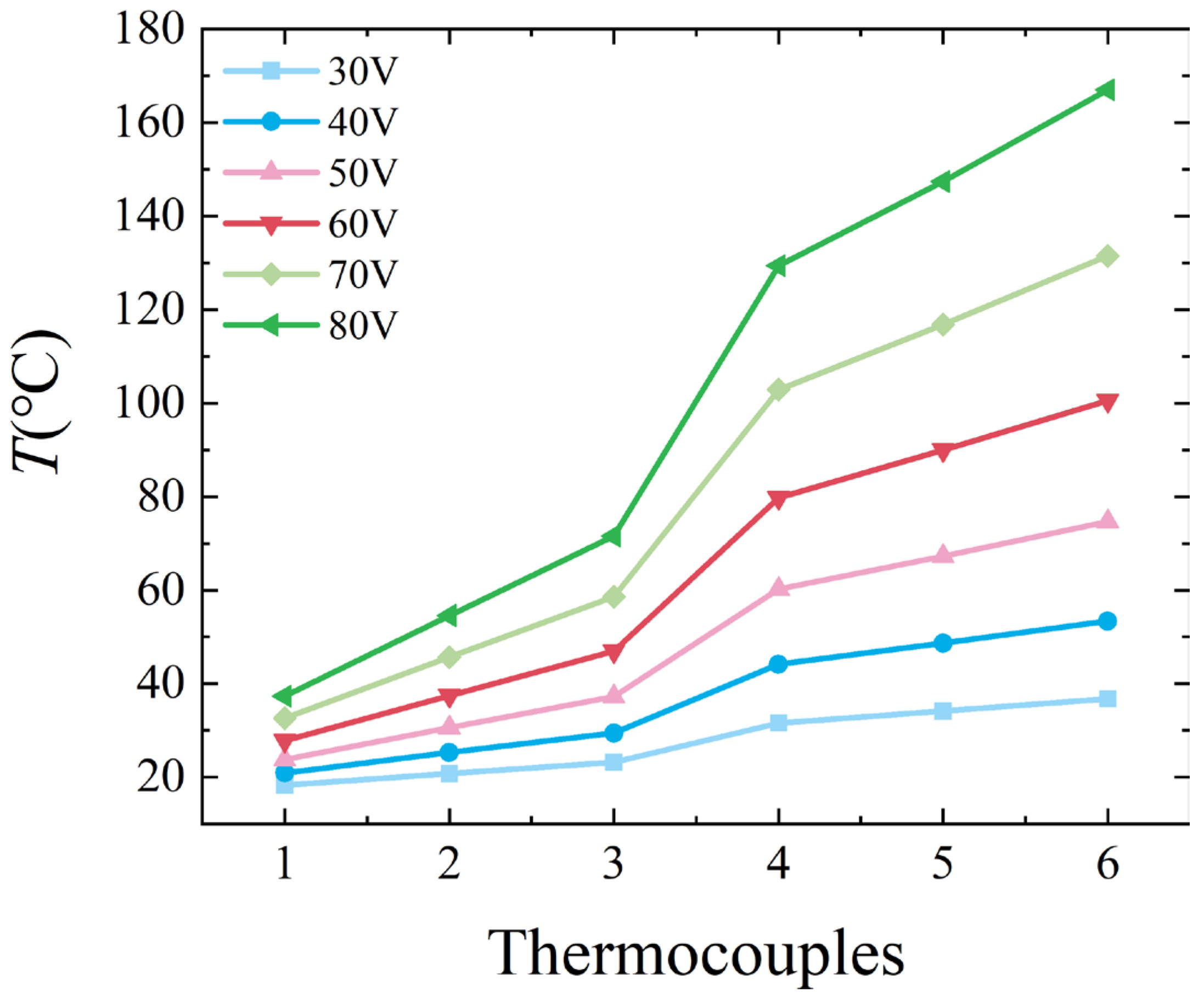
The thermal resistances of AlN substrates and silicone grease are measured by the device shown in Figure 2 and Figure 3. Six thermocouples (1–6) are arranged from top to bottom on the tungsten copper block. The temperature distribution of six measuring points is shown in Figure 5. The distribution trends of the six measured temperature points are the same at different heat fluxes with a temperature range of 20–170 °C. The temperature rise between points 3 and 4 accounts for more than 40%, which is larger than the other points. It is indicated that the thermal conductivity between points 3 and 4 is weakened due to the AlN substrate and silicone grease. The average of the five experiments is used to calculate the correlation between thermal resistance and temperature. The correlation between thermal resistance and temperature is shown in Equation (5) of Section 3. Figure 6 displays the comparison of the thermal resistance correlation with experimental data. R2 of the correlation is 0.986 and the mean absolute relative deviation (MARD) is 0.066, which means that the correlation can calculate the thermal resistance accurately.

4.2. Cooling Performance of the Hybrid Microchannel Heat Sink

In the closed-loop test system, a water-cooled condenser is used to continuously remove heat from the system, which keeps the inlet temperature of the heating module in a certain range of 3.6–4.8 °C. The initial operating pressure is 3.0 bar. There are three volumetric flow rates (0.86, 1.30 and 1.90 L/min). The range of heat flux is 50–400 W/cm2.
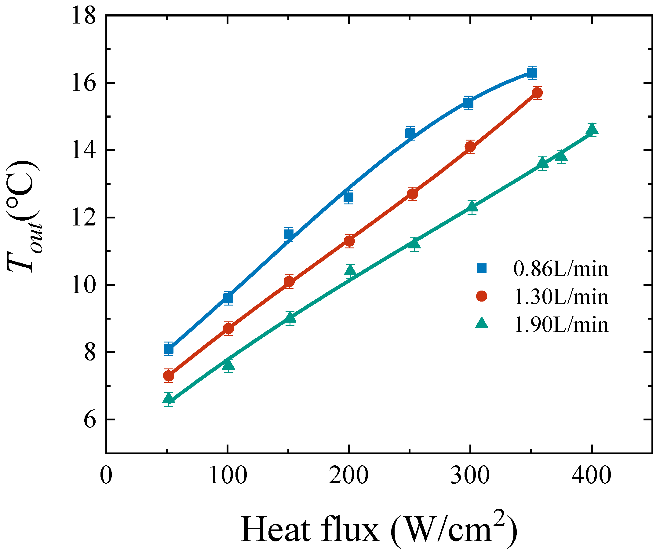
Figure 7 and Figure 8 show the temperatures of the heating wire and the outside wall and inside wall. It is shown that there is a temperature drop of about 20 °C for larger mass fluxes. Tow is 82.7 °C at 300 W/cm2 and 1.90 L/min whereas the one is 99.9 °C at 300 W/cm2 and 0.86 L/min. The heat transfer characteristics of the test module are investigated by analyzing the temperature distribution of the heating wire and the outer and inner walls. The temperature rise between the heating wire and the outside wall accounts for most of the overall temperature increase, up to 80%. It is indicated that thermal resistances of silicone grease and AlN substrates affect the cooling capacity of the test module significantly. The cooling performance is greatly improved when the volumetric flow rate is increased to 1.90 L/min. Tiw is 60.2 °C at 300 W/cm2 whereas the one of 0.86 L/min is 77.5 °C at 300 W/cm2. The temperature of outlet R134a is shown in Figure 9. When heat flux is increased from 50 W/cm2 to 300 W/cm2, the temperature rise is about 8 °C. The temperature of R134a increases from 4.2 °C to 16.3 °C when R134a flows from the inlet to the outlet at 0.86 L/min.
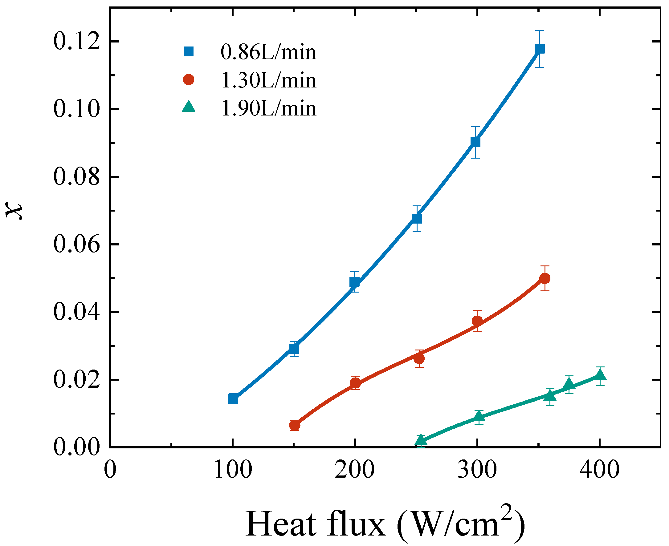
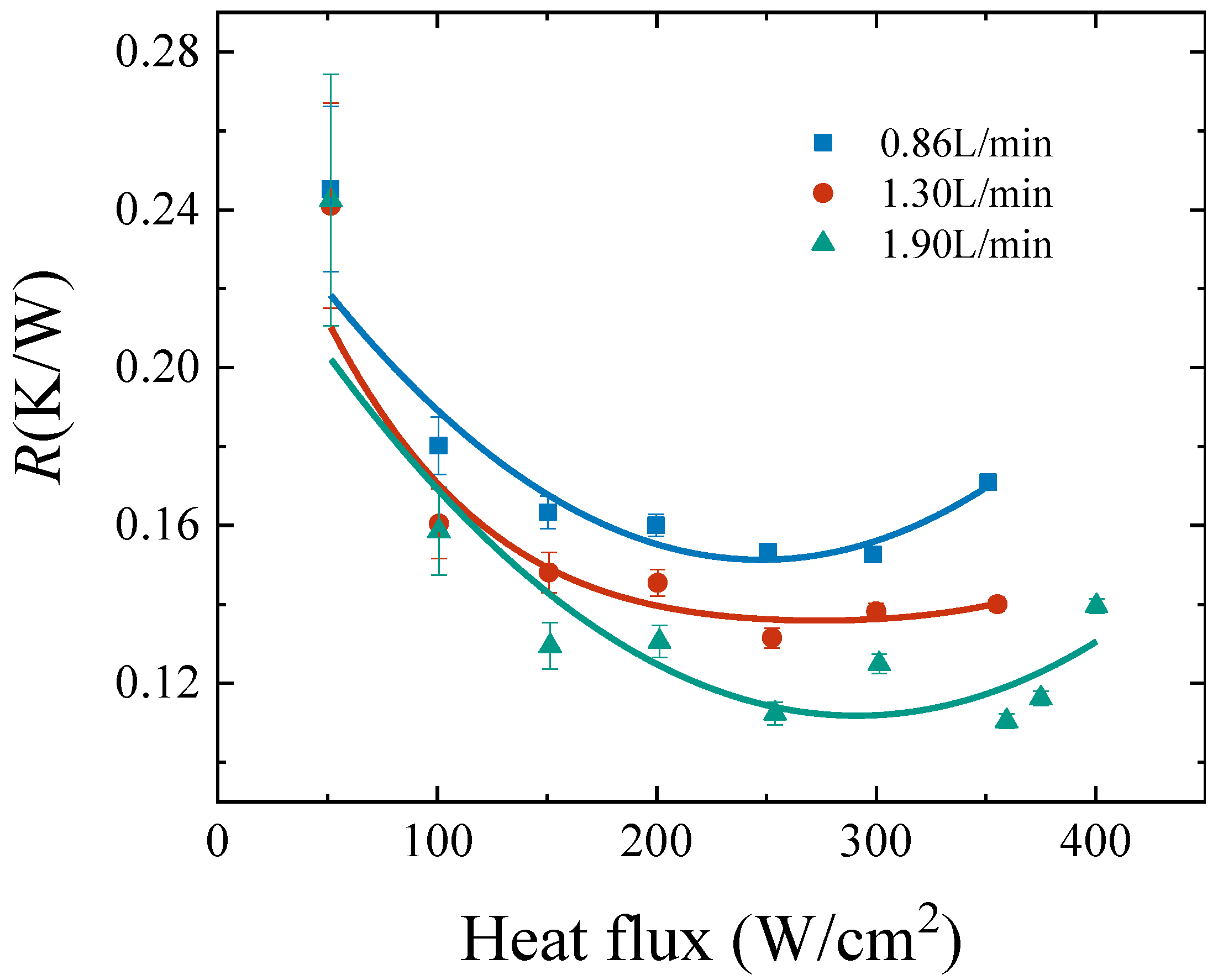
Figure 10 shows the outlet vapor quality at different heat fluxes. At 0.86, 1.30 and 1.90 L/min, the two-phase flow appears with heat fluxes of 100, 150 and 250 W/cm2, respectively. The outlet vapor quality of 0.86 L/min is 0.12 at 350 W/cm2 heat flux whereas the one of 1.90 L/min is 0.015. It is known that the cooling capacity is enhanced with the appearance of a two-phase flow. The thermal resistance for evaluating the cooling capacity of the heat sink is shown in Figure 11. There is a valley of thermal resistance at different heat fluxes, which represents the appearance of a two-phase flow. The cooling capacity is impaired when the heat flux increases continuously in the two-phase state. Therefore, there is an optimal heat flux at a certain flow rate at which the thermal resistance of the heat sink reaches the minimum. The thermal resistances are 0.15, 0.13 and 0.11 K/W for the cases of 0.86, 1.30 and 1.90 L/min, respectively. In addition to the thermal resistance of the heat sink, the thermal resistance of the test module also includes thermal interfacial resistance (AlN substrate and silicon grease). The thermal resistance distributions of the heat sink, AlN substrate and silicone grease are shown in Figure 12. The thermal resistances of the AlN substrate and silicone grease are almost always 0.14 K/W under different conditions, which accounts for 30–50% of the overall thermal resistance. It can be seen that the AlN substrate and silicone grease have a great influence on the cooling performance of the test module. Improper handling of the thermal interfacial resistance between the heat sink and the heating device can greatly reduce the performance of the heat sink. High thermal conductivity materials and great packaging processes are the key points to improve the performance of the heat sink.
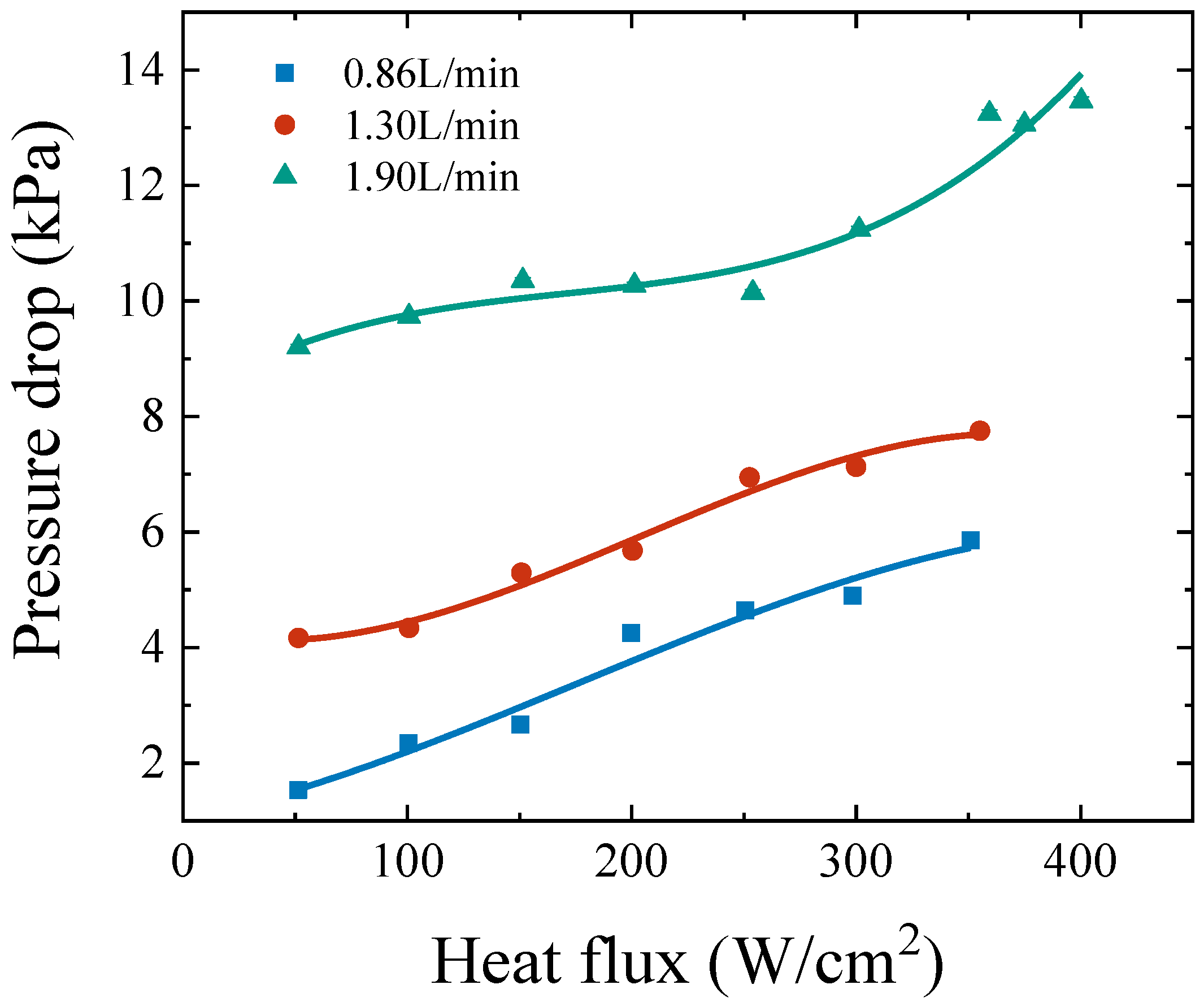
The pressure drop is another important parameter of microchannel heat sinks. The hybrid heat sink with a highly-dense micro-jet array (~100 jets per cm2 with jet width of 0.5 mm) has a lower thermal resistance with a larger pressure drop. Figure 13 shows the pressure drops at different heat fluxes. The pressure drops at 350 W/cm2 are 5.85, 7.75 and 13.24 kPa at 0.86, 1.30 and 1.90 L/min, respectively. The heat sink has a larger pressure drop with a high volumetric flow rate. The two-phase flow occurs at a large heat flux. Two-phase flow is more complicated at high heat flux where the pressure drop rises in an obvious way. The maximum pressure drop in the experiment is 13.46 kPa at 1.90 L/min and 400 W/cm2. The range of pressure drop is 1.54–13.46 kPa in the experiment.
Published studies [13,14,16,37,38,39] (experimental and numerical) on microchannel heat sinks for cooling high-power devices are compared with this work. Several important parameters including flow rate, pressure drop, thermal resistance, heat flux and heating area are compared. In the published studies with a heat flux of 200–600 W/cm2, the thermal resistance ranges from 0.23 to 0.71 K/W with a heating area of 10–30 mm2 and a pressure drop of 17–400 kPa. The heat sink in this work has a thermal resistance of 0.11 K/W, a 52% reduction compared to existing solutions. The maximum pressure drop is 13.5 kPa. It can be seen that the present hybrid scheme has a smaller pressure drop and thermal resistance. In addition to the pursuit of low thermal resistance at high heat flux, the heating area is also a very important evaluation parameter. The presented solution has a larger heating area of 210 mm2, which is 6 times larger than the existing schemes. The microjet array designed by Browne et al. [40] has a cooling capacity of 1100 W/cm2, which is 2.75 times higher than this work. However, its area of the heater is 1 mm2, which is much smaller than the presented scheme in the heating area. The microchannel heat sink has great cooling performance owing to the combination of a microchannel and jet impingement. A large aspect ratio microchannel can be fabricated by the superposition of microchannel plates. The jet impingement with a size of 0.2 mm × 0.5 mm × 10 mm has a great cooling capacity and reduces the risk of dryout. The large heating area with low thermal resistance and pressure drop is implemented by heat sinks combining a microchannel and jet impingement.

5. Conclusions

In this work, the cooling performance of a hybrid heat sink with micro-jets and microchannels was experimentally studied with a working fluid of R134a. The thermal conductivity of the AlN substrate was measured by using a laser flash analyzer (LFA 447), and the thermal resistances of silicone grease were determined by the steady-state method. The parameters including temperature, thermal resistance and pressure drop were investigated at different flow rates and heat fluxes. The largest heat flux of 400 W/cm2 was achieved on a heating area of 210 mm2 in the experiments. The lowest thermal resistance of the heat sink was 0.11 K/W, and the pressure drop was between 1.54 and 13.46 kPa. Results show that the combination of jet impingement and microchannel structures has excellent cooling performance and provides a promising solution for the thermal management of high-power devices with both a large area and a high heat flux.

Author Contributions

Data curation, R.X.; formal analysis, R.X., P.Z., L.C. and Y.Z.; resources, Y.H.; supervision, L.C. and Y.H.; writing—original draft, R.X.; writing—review and editing, R.X. and P.Z. All authors have read and agreed to the published version of the manuscript.

Funding

This project is supported by the National Natural Science Foundation of China (52176020), the Youth Innovation Team of Shaanxi Universities and Xi’an Jiaotong University Special Research Project for Basic Research Business Expenses (xzy022022030).

Institutional Review Board Statement

Not applicable.

Informed Consent Statement

Not applicable.

Data Availability Statement

Not applicable.

Conflicts of Interest

The authors declare no conflict of interest.

Nomenclature

Aarea (m2)hheat sink
hfluid enthalpy (kJ/kg)hwheating wire
Icurrent (A)inumber
mmass flow rate (kg/s)ininlet
Ppressure (MPa)iwinside wall
Qinput power (W)lvlatent heat of vaporization
qheat flux (W/m2)outoutlet
Reelectric resistance (Ω)owoutside wall
Rththermal resistance (K/W)satsaturation
Ttemperature (K)ththermal
Uvoltage (V)wwall
xvapor qualityAbbreviations
Greek symbolsAlNaluminum nitride
λthermal conductivity (W·m−1·K−1)CHFcritical heat flux
SubscriptsWCutungsten copper
eelectric

References

  1. Liu, X.; Zhao, W.; Xiong, L.; Liu, H. (Eds.) Packaging Process of High Power Semiconductor Lasers. In Packaging of High Power Semiconductor Lasers; Springer: New York, NY, USA, 2015; pp. 185–226. [Google Scholar]
  2. Mudawar, I. Two-Phase Microchannel Heat Sinks: Theory, Applications, and Limitations. J. Electron. Packag. 2011, 133, 041002. [Google Scholar] [CrossRef]
  3. Sourtiji, E.; Peles, Y. Flow boiling in microchannel with synthetic jet in cross-flow. Int. J. Heat Mass Transf. 2020, 147, 119023. [Google Scholar] [CrossRef]
  4. Tuckerman, D.B.; Pease, R.F.W. High-performance heat sinking for VLSI. IEEE Electron Device Lett. 1981, 2, 126–129. [Google Scholar] [CrossRef]
  5. Kreutz, E.W.; Pirch, N.; Ebert, T.; Wester, R.; Ollier, B.; Loosen, P.; Poprawe, R. Simulation of micro-channel heat sinks for optoelectronic microsystems. Microelectron. J. 2000, 31, 787–790. [Google Scholar] [CrossRef] [Green Version]
  6. Kandlikar, S.G. History, Advances, and Challenges in Liquid Flow and Flow Boiling Heat Transfer in Microchannels: A Critical Review. J. Heat Transf. 2012, 134, 034001. [Google Scholar] [CrossRef]
  7. Prajapati, Y.K.; Bhandari, P. Flow boiling instabilities in microchannels and their promising solutions—A review. Exp. Therm. Fluid Sci. 2017, 88, 576–593. [Google Scholar] [CrossRef]
  8. Muwanga, R.; Hassan, I.; MacDonald, R. Characteristics of Flow Boiling Oscillations in Silicon Microchannel Heat Sinks. J. Heat Transf. 2007, 129, 1341–1351. [Google Scholar] [CrossRef]
  9. Zhang, T.; Peles, Y.; Wen, J.T.; Tong, T.; Chang, J.-Y.; Prasher, R.; Jensen, M.K. Analysis and active control of pressure-drop flow instabilities in boiling microchannel systems. Int. J. Heat Mass Transf. 2010, 53, 2347–2360. [Google Scholar] [CrossRef]
  10. Oudah, S.K.; Fang, R.; Tikadar, A.; Salman, A.S.; Khan, J.A. An experimental investigation of the effect of multiple inlet restrictors on the heat transfer and pressure drop in a flow boiling microchannel heat sink. Int. J. Heat Mass Transf. 2020, 153, 119582. [Google Scholar] [CrossRef]
  11. Kozłowska, A.; Łapka, P.; Seredyński, M.; Teodorczyk, M.; Dąbrowska-Tumańska, E. Experimental study and numerical modeling of micro-channel cooler with micro-pipes for high-power diode laser arrays. Appl. Therm. Eng. 2015, 91, 279–287. [Google Scholar] [CrossRef]
  12. Drummond, K.P.; Back, D.; Sinanis, M.D.; Janes, D.B.; Peroulis, D.; Weibel, J.A.; Garimella, S.V. A hierarchical manifold microchannel heat sink array for high-heat-flux two-phase cooling of electronics. Int. J. Heat Mass Transf. 2018, 117, 319–330. [Google Scholar] [CrossRef] [Green Version]
  13. Jia, G.; Qiu, Y.; Yan, A.; Yao, S.; Wang, Z. Laser three-dimensional printing microchannel heat sink for high-power diode laser array. Opt. Eng. 2016, 55, 096105. [Google Scholar] [CrossRef]
  14. Deng, Z.; Shen, J.; Dai, W.; Li, K.; Song, Q.; Gong, W.; Dong, X.; Gong, M. Experimental study on cooling of high-power laser diode arrays using hybrid microchannel and slot jet array heat sink. Appl. Therm. Eng. 2019, 162, 114242. [Google Scholar] [CrossRef]
  15. Farsad, E.; Abbasi, S.P.; Zabihi, M.S. Fluid Flow and Heat Transfer in a Novel Microchannel Heat Sink Partially Filled With Metal Foam Medium. J. Therm. Sci. Eng. Appl. 2014, 6, 021011. [Google Scholar] [CrossRef]
  16. Baraty Beni, S.; Bahrami, A.; Salimpour, M.R. Design of novel geometries for microchannel heat sinks used for cooling diode lasers. Int. J. Heat Mass Transf. 2017, 112, 689–698. [Google Scholar] [CrossRef]
  17. Kim, C.-B.; Leng, C.; Wang, X.-D.; Wang, T.-H.; Yan, W.-M. Effects of slot-jet length on the cooling performance of hybrid microchannel/slot-jet module. Int. J. Heat Mass Transf. 2015, 89, 838–845. [Google Scholar] [CrossRef]
  18. Robinson, A.J.; Kempers, R.; Colenbrander, J.; Bushnell, N.; Chen, R. A single phase hybrid micro heat sink using impinging micro-jet arrays and microchannels. Appl. Therm. Eng. 2018, 136, 408–418. [Google Scholar] [CrossRef]
  19. Li, X.-Y.; Wang, S.-L.; Wang, X.-D.; Wang, T.-H. Selected porous-ribs design for performance improvement in double-layered microchannel heat sinks. Int. J. Therm. Sci. 2019, 137, 616–626. [Google Scholar] [CrossRef]
  20. Wang, S.-L.; Chen, L.-Y.; Zhang, B.-X.; Yang, Y.-R.; Wang, X.-D. A new design of double-layered microchannel heat sinks with wavy microchannels and porous-ribs. J. Therm. Anal. Calorim. 2020, 141, 547–558. [Google Scholar] [CrossRef]
  21. Zhou, F.; Zhou, W.; Zhang, C.; Qiu, Q.; Yuan, D.; Chu, X. Experimental and numerical studies on heat transfer enhancement of microchannel heat exchanger embedded with different shape micropillars. Appl. Therm. Eng. 2020, 175, 115296. [Google Scholar] [CrossRef]
  22. Woodcock, C.; Ng’oma, C.; Sweet, M.; Wang, Y.; Peles, Y.; Plawsky, J. Ultra-high heat flux dissipation with Piranha Pin Fins. Int. J. Heat Mass Transf. 2019, 128, 504–515. [Google Scholar] [CrossRef]
  23. Liao, W.-R.; Chien, L.-H.; Ghalambaz, M.; Yan, W.-M. Experimental study of boiling heat transfer in a microchannel with nucleated-shape columnar micro-pin-fins. Int. Commun. Heat Mass Transf. 2019, 108, 104277. [Google Scholar] [CrossRef]
  24. Cheng, X.; Wu, H. Improved flow boiling performance in high-aspect-ratio interconnected microchannels. Int. J. Heat Mass Transf. 2021, 165, 120627. [Google Scholar] [CrossRef]
  25. Deng, D.; Xie, Y.; Huang, Q.; Wan, W. On the flow boiling enhancement in interconnected reentrant microchannels. Int. J. Heat Mass Transf. 2017, 108, 453–467. [Google Scholar] [CrossRef]
  26. Deng, D.; Chen, L.; Wan, W.; Fu, T.; Huang, X. Flow boiling performance in pin fin- interconnected reentrant microchannels heat sink in different operational conditions. Appl. Therm. Eng. 2019, 150, 1260–1272. [Google Scholar] [CrossRef]
  27. Li, W.; Ma, J.; Alam, T.; Yang, F.; Khan, J.; Li, C. Flow boiling of HFE-7100 in silicon microchannels integrated with multiple micro-nozzles and reentry micro-cavities. Int. J. Heat Mass Transf. 2018, 123, 354–366. [Google Scholar] [CrossRef]
  28. Zhou, J.; Luo, X.; Pan, Y.; Wang, D.; Xiao, J.; Zhang, J.; He, B. Flow boiling heat transfer coefficient and pressure drop in minichannels with artificial activation cavities by direct metal laser sintering. Appl. Therm. Eng. 2019, 160, 113837. [Google Scholar] [CrossRef]
  29. Cheng, X.; Wu, H. Experimental Comparison of Flow Boiling Heat Transfer in High Aspect Ratio Microchannels With Plain and Grooved Walls. J. Heat Transf. 2020, 142, 121602. [Google Scholar] [CrossRef]
  30. He, B.; Luo, X.; Yu, F.; Zhou, J.; Zhang, J. Flow boiling characteristics in bi-porous minichannel heat sink sintered with copper woven tape. Int. J. Heat Mass Transf. 2020, 158, 119988. [Google Scholar] [CrossRef]
  31. Li, H.-W.; Zhang, C.-Z.; Yang, D.; Sun, B.; Hong, W.-P. Experimental investigation on flow boiling heat transfer characteristics of R141b refrigerant in parallel small channels filled with metal foam. Int. J. Heat Mass Transf. 2019, 133, 21–35. [Google Scholar] [CrossRef]
  32. Zhang, S.; Sun, Y.; Yuan, W.; Tang, Y.; Tang, H.; Tang, K. Effects of heat flux, mass flux and channel width on flow boiling performance of porous interconnected microchannel nets. Exp. Therm. Fluid Sci. 2018, 90, 310–318. [Google Scholar] [CrossRef]
  33. Li, W.; Yang, F.; Qu, X.; Li, C. Wicking Nanofence-Activated Boundary Layer to Enhance Two-Phase Transport in Microchannels. Langmuir 2020, 36, 15536–15542. [Google Scholar] [CrossRef] [PubMed]
  34. Kousalya, A.S.; Singh, K.P.; Fisher, T.S. Heterogeneous wetting surfaces with graphitic petal-decorated carbon nanotubes for enhanced flow boiling. Int. J. Heat Mass Transf. 2015, 87, 380–389. [Google Scholar] [CrossRef]
  35. Ghosh, D.P.; Sharma, D.; Mohanty, D.; Saha, S.K.; Raj, R. Facile Fabrication of Nanostructured Microchannels for Flow Boiling Heat Transfer Enhancement. Heat Transf. Eng. 2019, 40, 537–548. [Google Scholar] [CrossRef]
  36. Ma, L.; Zhao, X.; Sun, H.; Wu, Q.; Liu, W. Experimental Study of Single Phase Flow in a Closed-Loop Cooling System with Integrated Mini-Channel Heat Sink. Entropy 2016, 18, 128. [Google Scholar] [CrossRef] [Green Version]
  37. Dix, J.; Jokar, A. Fluid and thermal analysis of a microchannel electronics cooler using computational fluid dynamics. Appl. Therm. Eng. 2010, 30, 948–961. [Google Scholar] [CrossRef]
  38. Farsad, E.; Abbasi, S.P.; Zabihi, M.S.; Sabbaghzadeh, J. Numerical simulation of heat transfer in a micro channel heat sinks using nanofluids. Heat Mass Transf. 2011, 47, 479–490. [Google Scholar] [CrossRef]
  39. Deng, Z.; Shen, J.; Gong, W.; Dai, W.; Gong, M. Temperature distribution and thermal resistance analysis of high-power laser diode arrays. Int. J. Heat Mass Transf. 2019, 134, 41–50. [Google Scholar] [CrossRef]
  40. Browne, E.A.; Michna, G.J.; Jensen, M.K.; Peles, Y. Experimental Investigation of Single-Phase Microjet Array Heat Transfer. J. Heat Transf. 2010, 132, 041013. [Google Scholar] [CrossRef]
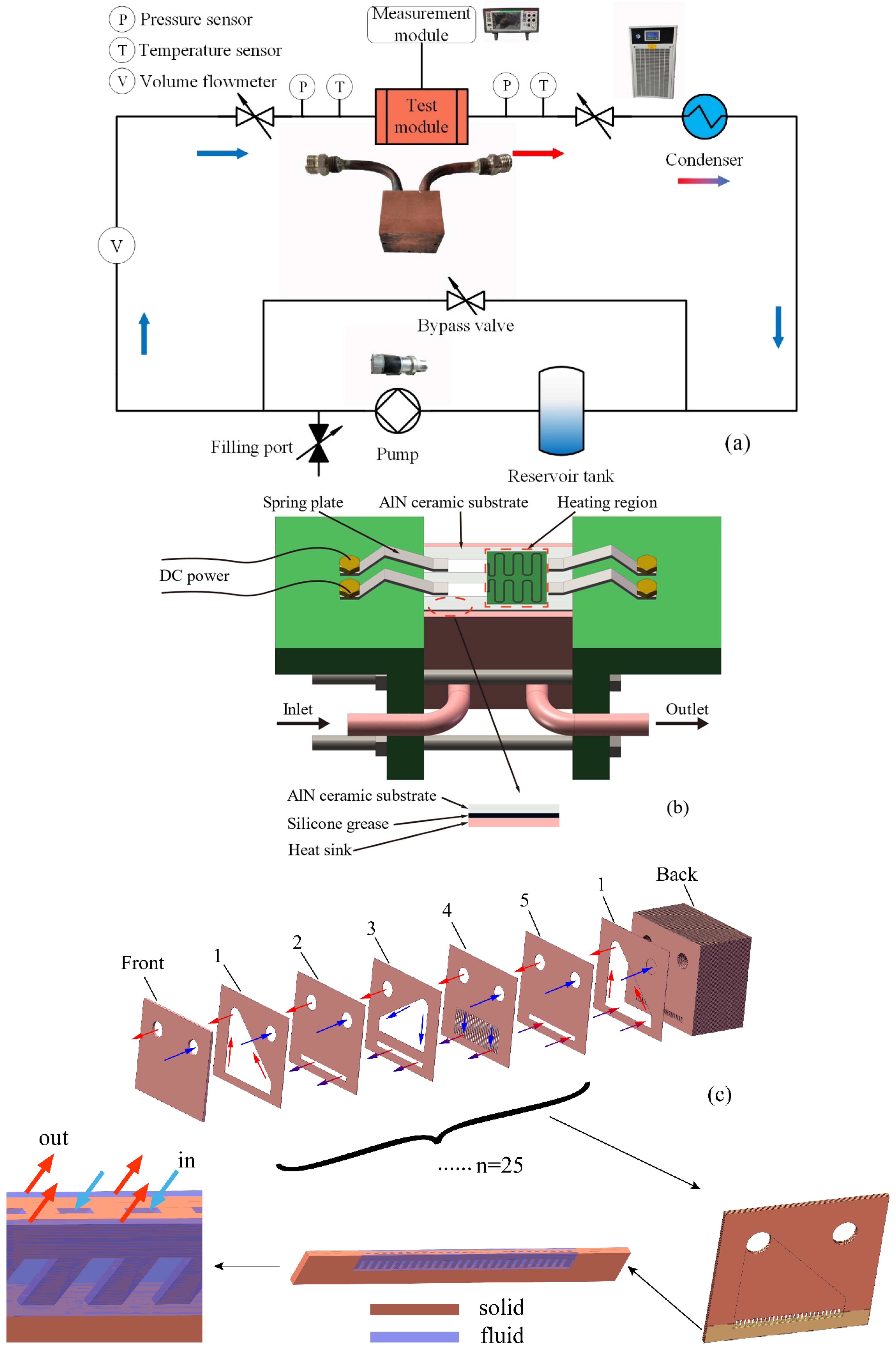
Figure 1. Schematic of closed-loop test apparatus (a), the test module (b), and the structure of the hybrid heat sink (c).
Applsci 12 13033 g001
Figure 2. Schematic of measuring device for thermal contact resistance.
Applsci 12 13033 g002
Figure 3. Schematic of the core structure in the measuring device.
Applsci 12 13033 g003
Figure 4. Repeatability tests for the temperature of heating wire Thw.
Applsci 12 13033 g004
Figure 5. Temperature distribution of six measuring points.
Applsci 12 13033 g005
Figure 6. Comparison of the thermal resistance correlation with experiment data.
Applsci 12 13033 g006
Figure 7. The temperatures of heating wire at different heat fluxes.
Applsci 12 13033 g007
Figure 8. The temperatures of the heat sink at different heat fluxes: (a) outside wall and (b) inside wall.
Applsci 12 13033 g008
Figure 9. The temperatures of outlet R134a.
Applsci 12 13033 g009
Figure 10. The outlet vapor quality at different heat fluxes.
Applsci 12 13033 g010
Figure 11. The thermal resistances of the heat sink.
Applsci 12 13033 g011
Figure 12. The thermal resistances of the test module.
Applsci 12 13033 g012
Figure 13. The pressure drops at different heat fluxes.
Applsci 12 13033 g013
Publisher’s Note: MDPI stays neutral with regard to jurisdictional claims in published maps and institutional affiliations.