1. Introduction
Nowadays, the problem of energy shortage is becoming more and more prominent. The efficient use of energy has become very important to the sustainable development of the world. To improve the heat exchange efficiency of heat transfer equipment and reduce the flow resistance loss has been paid attention to in many fields such as nuclear energy, electric power, petroleum, and petrochemical [
1,
2,
3].
The tubular heat exchanger the heat exchange equipment which main heat exchange element is the heat exchange tube. Because of its high heat exchange efficiency, mature and reliable, and easy to manufacture and install, it has been widely used in various heat exchange occasions in industrial production. The traditional tubular heat exchange equipment mostly uses an ordinary smooth tube as a heat exchange tube, which is simple to process and manufacture but with a low heat exchange efficiency. Therefore, from the perspective of improving the heat transfer efficiency of heat exchanger tubes and improving the energy utilization rate, many researchers have tried to introduce elements such as fins, grooves, bumps, wings, and dimple structures into the tubular heat exchanger with the purpose of improving heat transfer performance.
There are many publications related to the enhanced surface heat transfer studies. Afanasyev et al. [
4] presented the research results on the influence of spherical cavities on flow resistance and heat transfer on a smooth plate, which can be considered as the earliest report on the application of dimple structure in the field of heat transfer. They measured the flow and heat transfer of the dimpled plate. By comparing with the smooth plate, it was found that the heat transfer of the cell channel was enhanced by 30–40% without increasing the flow resistance. The heat transfer characteristics and flow resistance of the dimpled heat exchange tube and the traditional fin heat exchange tube were compared and analyzed by Yaroslav [
5]. The results showed that under the condition of the same heat transfer capacity, the dimpled heat exchange tube had smaller flow resistance and better comprehensive heat transfer performance. The numerical calculation research on circular cross section pipelines containing concave dimple was carried out by Li et al. [
6] The influence of concave dimple on heat transfer effect of pipelines under different arrangement of structural parameters were analyzed. The results showed that the structure of concave dimple should be reasonably designed to avoid the influence of vortex dead zone on heat transfer effect. Liao et al. [
7] used the Realizable k-ε model to numerically simulate the heat transfer of protruded oval dimpled pipes, focusing on analyzing the influence of the number and distribution of dimple on the flow and heat transfer characteristics of the pipes. Li et al. [
8] carried out numerical simulation of the spiral protrusion dimple tube. The reasons for enhanced heat transfer of the protrusion dimple were analyzed from the perspective of flow field structure. The optimal relative depth (H/d) range of the dimple were determined by analyzing the comprehensive heat transfer coefficient. experiments and numerical simulations on tube heat exchangers containing dimple and rough surface heat exchange tubes were carried out by Li [
9] et al. The results showed that compared with the smooth tube of the same size, the heat transfer capacity of the heat transfer tube combined with the rough wall surface can be increased by more than 200%, and the comprehensive heat transfer coefficient can reach more than 1.5. Through the above-mentioned literature and experiment, dimple will cause considerable increase in pressure drop. How to enhance the heat transfer with limited pressure-drop increase has become the focus of research.
In the processing process of the dimpled tube, the protrusion dimple will be formed on the inner wall during the processing of the concave dimple on the outer wall. Due to the influence of wall thickness, the size of protrusion dimple is often larger than the corresponding concave dimple. Previous studies generally only considered the influence of the protrusion dimple or concave dimple structure on the heat transfer performance of the pipe. According to the results of previous studies, dimple enhances the heat transfer effect and also increases the flow resistance. Whether the change of flow field will affect each other and then affect the comprehensive heat transfer effect of the heat exchange tube when protrusion dimple and concave dimple coexist remains to be further studied. Therefore, based on the structure of tubular heat exchangers in petrochemical enterprises, this paper uses the CFD software Fluent to analyze the influence of the inner tubes with different sizes of dimple concave and protrusion on the heat transfer capacity of both tube side and shell side of tubular heat exchangers. A comprehensive evaluation of the heat transfer performance of dimpled heat exchange tubes is carried out.
2. Numerical Simulation
2.1. Mathematical Model
The following assumptions are made in order to simplify the calculation:
- (1)
The flow in the tube is three-dimensional steady flow and the medium is incompressible Newtonian fluid.
- (2)
Gravity and buoyancy force are ignored.
- (3)
There is no slipping on the wall.
- (4)
The flow and heat transfer are assumed to be steady state processes [
10].
According to the above assumptions, the fluid in the tube should satisfy the following equations [
11].
The continuity conservation equation can be written as:
The momentum conservation equation can be written as:
where
,
, and
are viscous force component of three directions.
,
, and
are three components of force per unit mass.
The problem of heat transfer between a fluid and a solid region needs to be calculated, and the model consists of two flow regions separated by a solid [
12].
The energy conservation equation can be written as:
Energy conservation equation of solid:
where
is stress tensor, internal energy,
E is internal energy,
is effective thermal conductivity.
is component diffusion flux,
is heat source item.
2.2. Grid and Calculation Conditions
2.2.1. Geometric Model
Based on the structure of the tube heat exchanger [
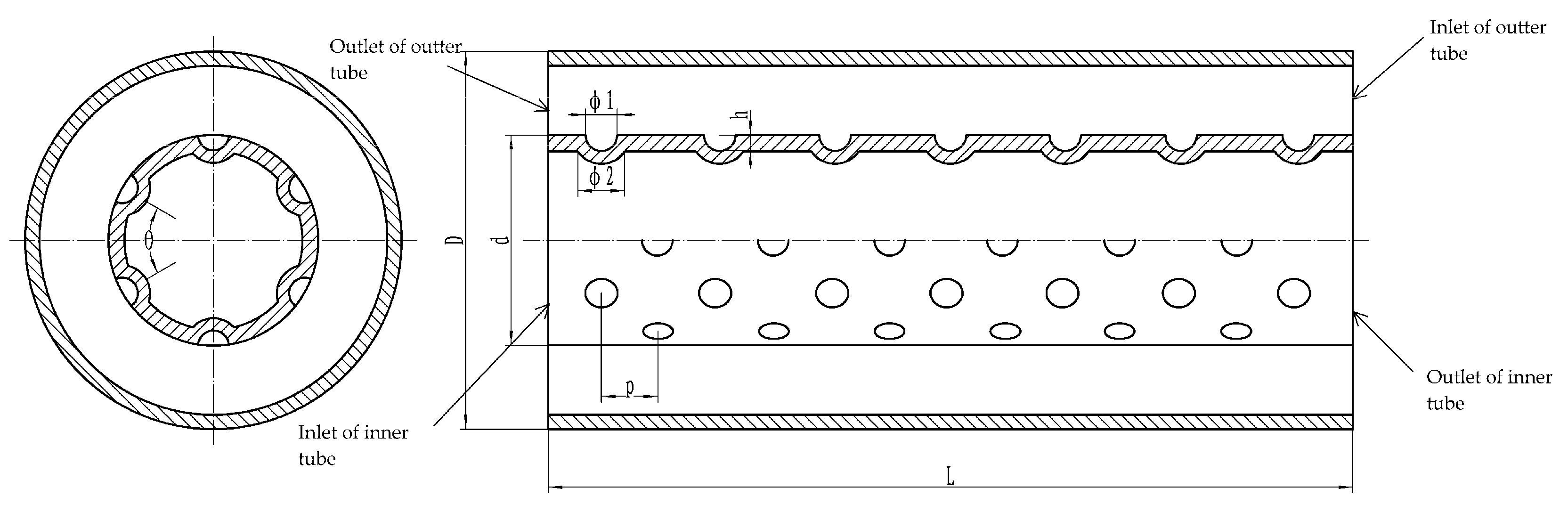
12], the calculation model for heat transfer performance of tube heat exchanger is established. The tube heat exchanger is composed of an inner dimpled tube and a smooth outer tube. To improve the computational efficiency, only part of the tube is cut off for analysis on the premise of ensuring the full development of the flow. The dimpled tube is shown structure
Figure 1. Inner tube fluid flows from left to right and outer tube fluid flows from right to left. On one section, there are 6 dimples in the circumference. On the next section, stagger by 30 degrees. The specific dimensions of a series of dimple structures are shown in
Table 1. All units of length are in mm.
2.2.2. Computational Grid
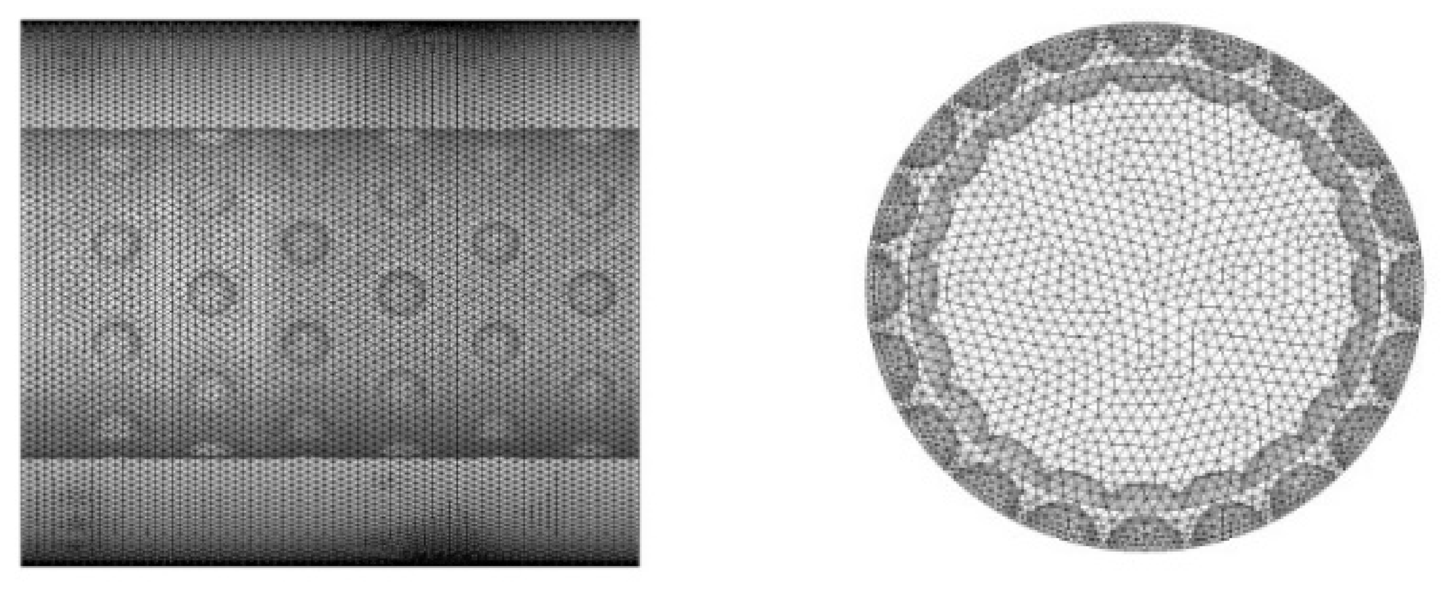
Take the dimpled structure with symbol of 10–15 as the object, the grid independence verification was carried out for four kinds of meshes with the number of about 1.67 million, 2.25 million, 3.05 million and 4.25 million, and the comparison found that the errors of Nusselt number calculated in the pipe flow between adjacent density meshes were 12.57%, 6.82%, and 2.43%, respectively. The Nusselt numbers of different grids are shown in
Table 2. The error between 3.05 million grid and 4.25 million grid is acceptable. Therefore, 3.05 million grid is selected as the computing grid, and its division form is shown in the
Figure 2. For different structures, only the cell position changed, so other models were meshed according to this density.
2.2.3. Computational Boundary Condition
The inner tube is a high temperature fluid, and the annulus space is a low temperature fluid. Water flow medium was used for numerical calculation, and 20 G was selected as the pipe wall material, and its physical parameters were shown in
Table 3.
The temperature of water medium is between 15–273 °C, and the density is between 790–1008 kg/m
3 under 20 MPa pressure. Therefore, the physical parameters of water medium are given by multi-point linear interpolation method in numerical simulation [
9].
The boundary parameters are determined and calculated according to the actual working conditions, and the specific Settings are shown in
Table 4. Inlet of inner tube is set to velocity inlet.
Steady-state numerical calculation is adopted, and the specific discrete scheme and algorithm are shown in
Table 5.
When the absolute value of energy residual is stable below 1 × 10⁻⁶ and other terms are lower than 1 × 10⁻⁶, it is judged to be convergent. The energy equation has an underrelaxation factor of 0.5, and the rest remain default in Fluent.
3. Evaluation Method of Heat Transfer Performance
To enhance heat transfer, resistance loss should be considered at the same time, so the comprehensive heat transfer factor
PEC is used to evaluate the heat transfer performance [
13].
where
,
are Nusselt number and resistance coefficient of dimpled tube,
,
are Nusselt number and resistance coefficient of smooth tube.
The
Nu and
f can be written as [
14,
15]:
where
hi is convective heat transfer coefficient,
is hydraulic diameter,
is heat conductivity coefficient,
is the pressure drop on the flow channel length
L;
is the density of fluid,
is the average velocity of the fluid on the cross section of the flow channel.
When , the comprehensive heat transfer performance of dimpled tube is higher than that of smooth tube. When , the comprehensive heat transfer performance of dimpled tube is lower than that of smooth tube.
4. Calculation and Analysis
4.1. Analysis of Flow Characteristics in Dimpled Tube
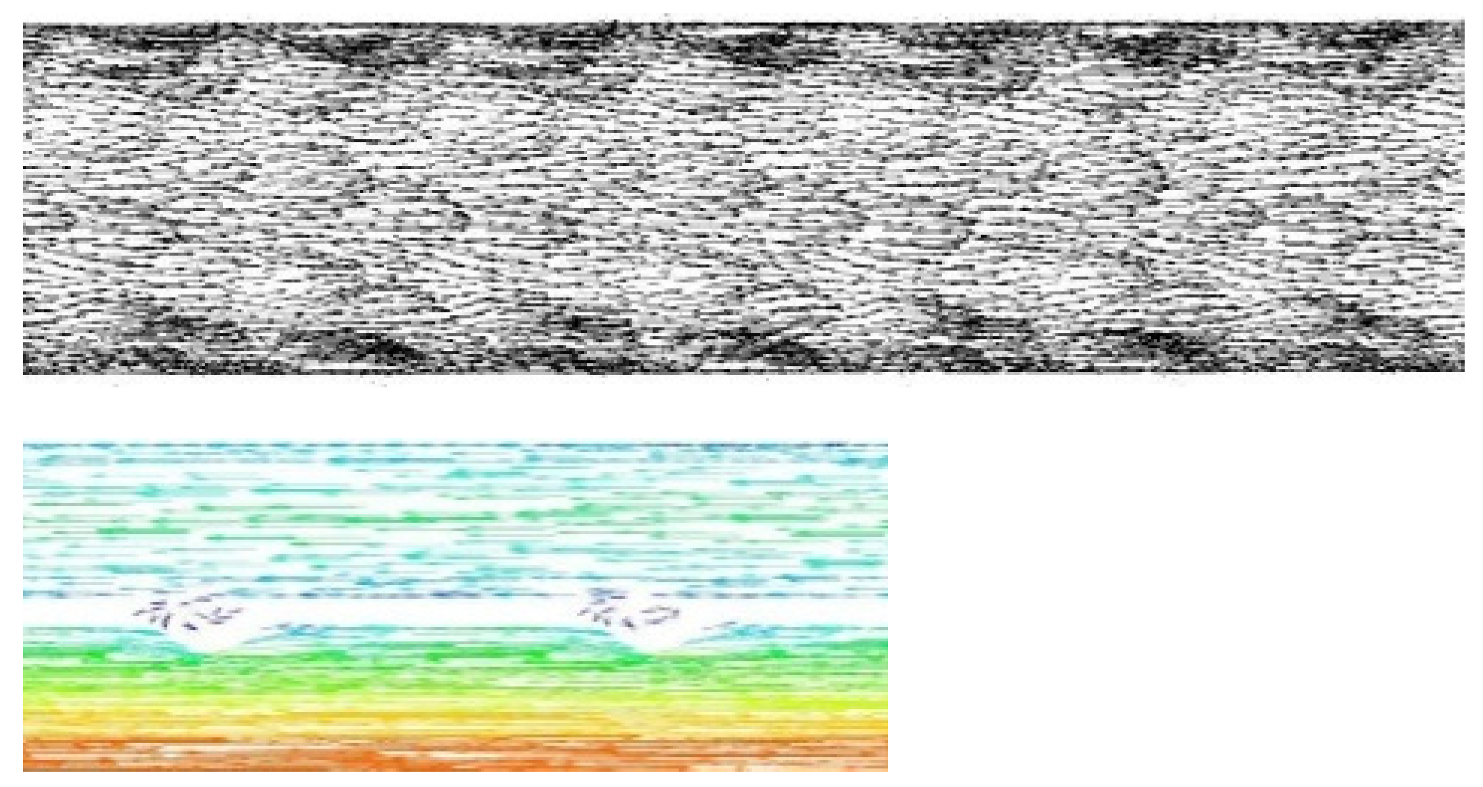
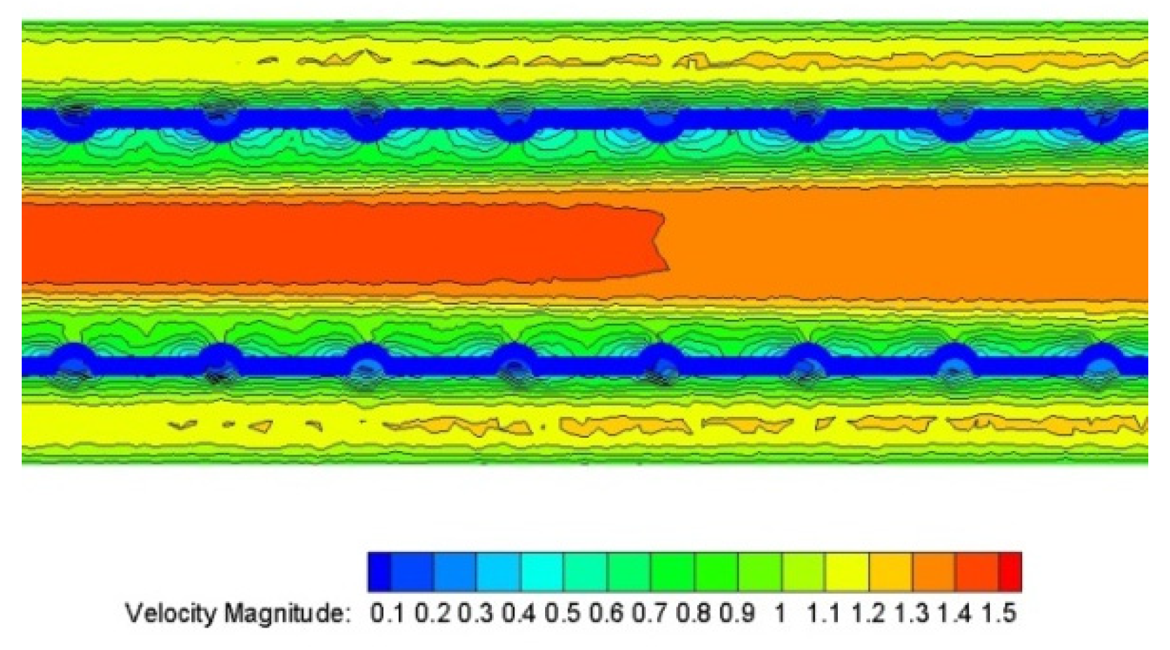
Figure 3 and
Figure 4 show the velocity vector diagram and velocity cloud diagram near the wall when the Reynolds number is 20,000 of the 10–15 dimpled tube. Eddy current will form in the concave cell when the fluid flows through the concave dimple on the outer wall of the tube. The flow velocity in the eddy current is significantly lower than that of the main flow, which is equivalent to the existence of a certain range of flow dead zone. To some extent, the heat transfer coefficient will be reduced, but the heat transfer area will be increased, and the heat transfer time will be increased. However, the velocity and direction will change to some extent, but basically no flow dead zone will be generated when the tube side fluid flows through the protruding of the inner wall of the tube. The fluid at the rear of the cell impacts upward on the smooth wall surface, resulting in mixing between the near-wall fluid and the internal fluid, damaging the boundary layer and enhancing the turbulence intensity.
The cloud diagram of the temperature distribution in and outside the tube is shown in
Figure 5. The temperature gradient on the protrusion surface between the concave cell and the protrusion surface of the cell is significantly larger than that of the non-dimple, and the fluid generates more energy exchange in the structure of the cell. At the leading edge and trailing edge of the concave tin cell, the flow dead zone formed by the abrupt curvature thickens the temperature boundary layer in this region, and the convective heat transfer basically presents the mode of heat conduction, and its heat transfer capacity is close to or even lower than that of the smooth tube.
4.2. Heat Transfer Performance of Dimpled Tubes with Different Dimple Sizes
In order to facilitate the analysis, with the same structural parameters and numerical calculation method, the numerical simulation of heat transfer performance with smooth wall heat exchange tube is calculated and compared with those of the dimpled heat exchange tube.
4.2.1. Heat Transfer Performance of Different Dimpled Tubes
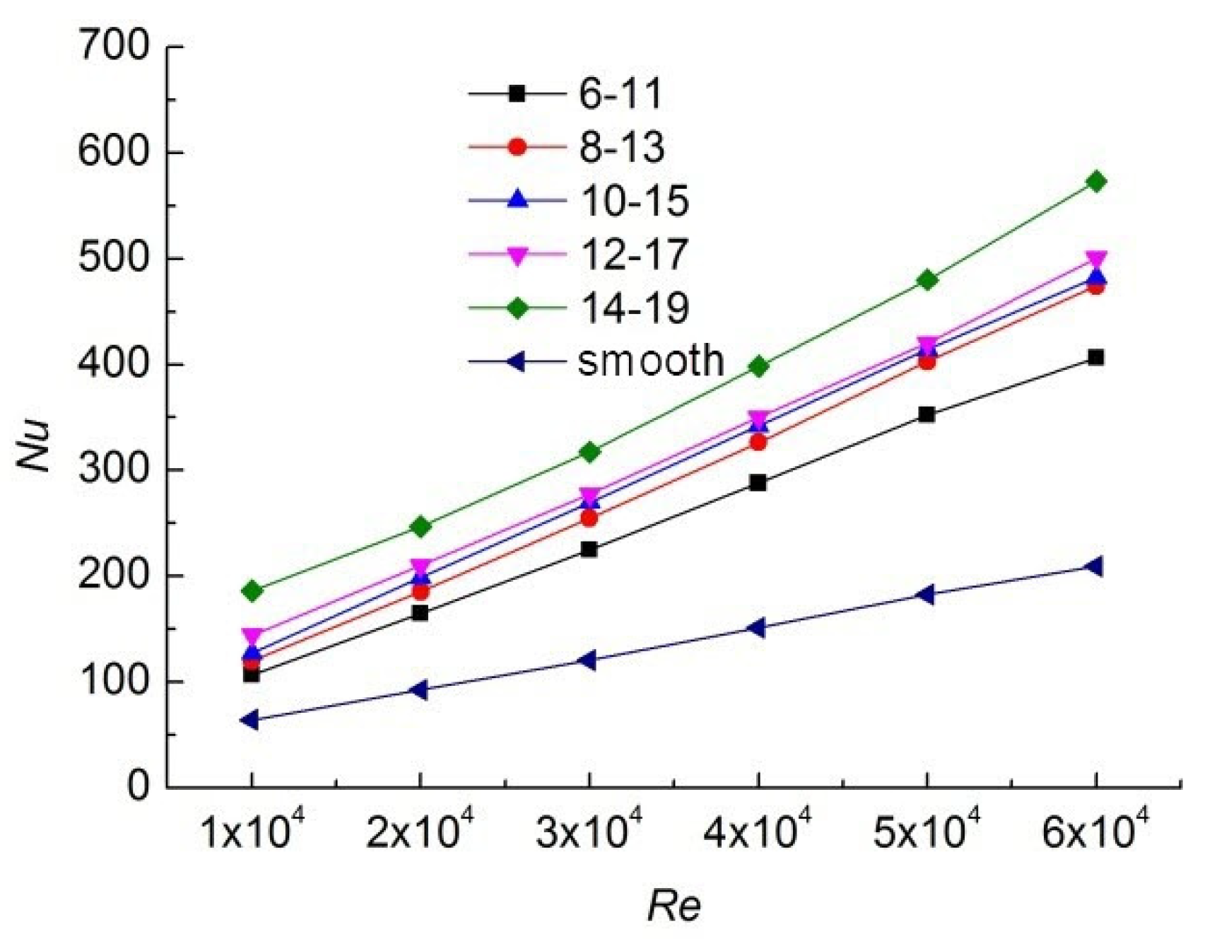
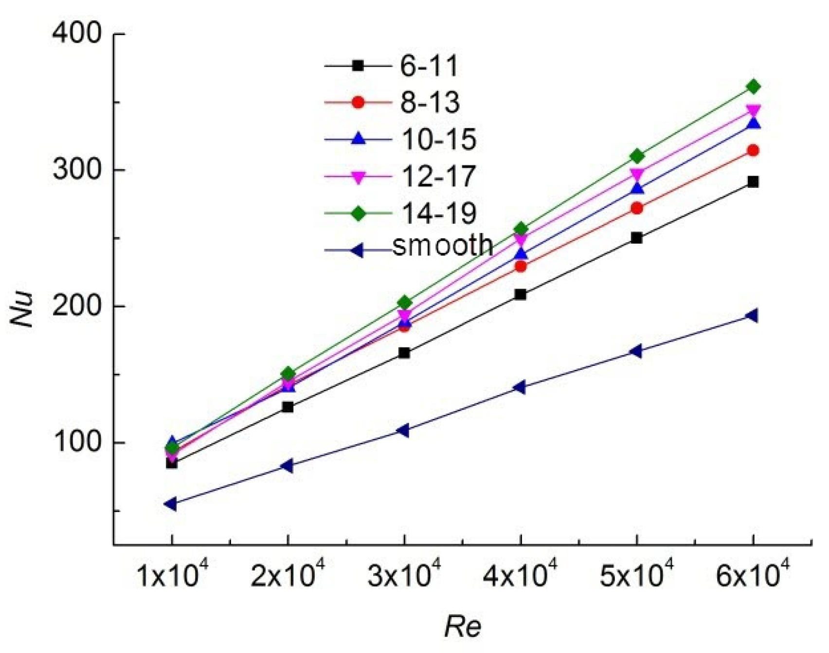
The heat transfer performance of the cell tube was evaluated by the Nusselt number
Nu. Obviously, as shown in
Figure 6 and
Figure 7, the dimpled structure significantly improves the heat transfer performance.
Nu of dimpled tubes with different structures increases more than twice as much as that of smooth tubes at different Reynolds numbers, regardless of tube side or shell side. In the studied range, the heat transfer performance increases linearly with the Reynolds number. Under the same Reynolds number, the larger the cell size, the stronger the heat transfer performance. Compared with other sizes, the heat transfer performance of the 14 mm dimple structure is significantly increased. Compared with the smooth tube, the protrusion dimple enhances the heat transfer by 1.94~2.74 times in the tube side, and the concave dimple enhances the heat transfer by 1.50~1.87 times in the shell side. The enhancement effect is increasing with Reynolds number.
4.2.2. Comparison of Resistance Characteristics of Dimpled Heat Exchange Tubes
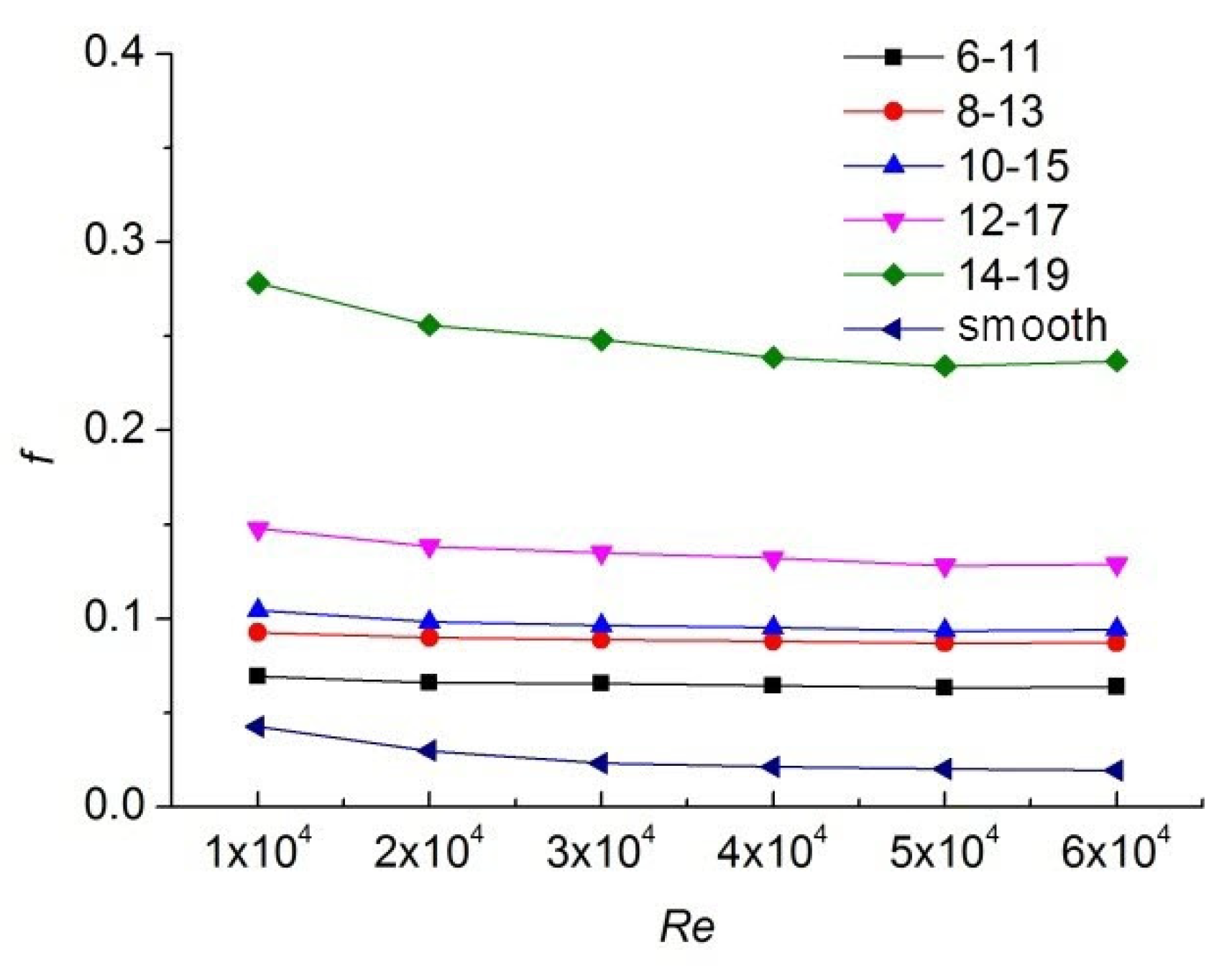
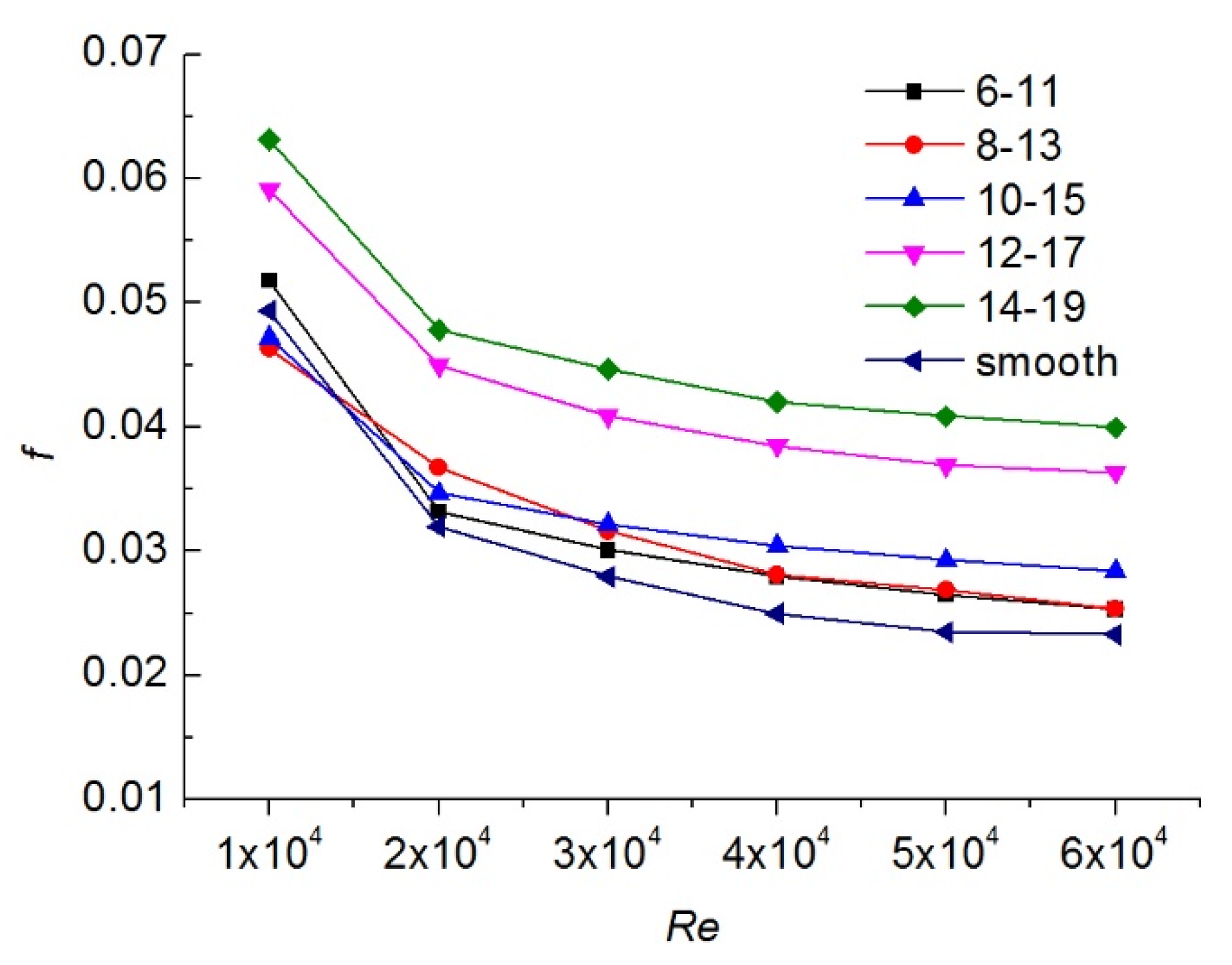
The comparison curves of the resistance coefficients between tube and shell are shown in
Figure 8 and
Figure 9. The resistance of tube is increased with the enhancement of heat transfer capacity. The bigger dimple will generate the greater resistance, which is particularly obvious in the tube side. Meanwhile, the resistance coefficient of the tube side is basically an order of magnitude larger than the resistance coefficient of the shell side, and the protrusion dimple will generate greater resistance. However, when the Reynolds number in the shell side is very low, the resistance generated by the small-size dimple structure does not increase significantly which is compared with that of the smooth tube. When Reynolds number is 10,000, the resistance coefficient
f is very close to smooth tube.
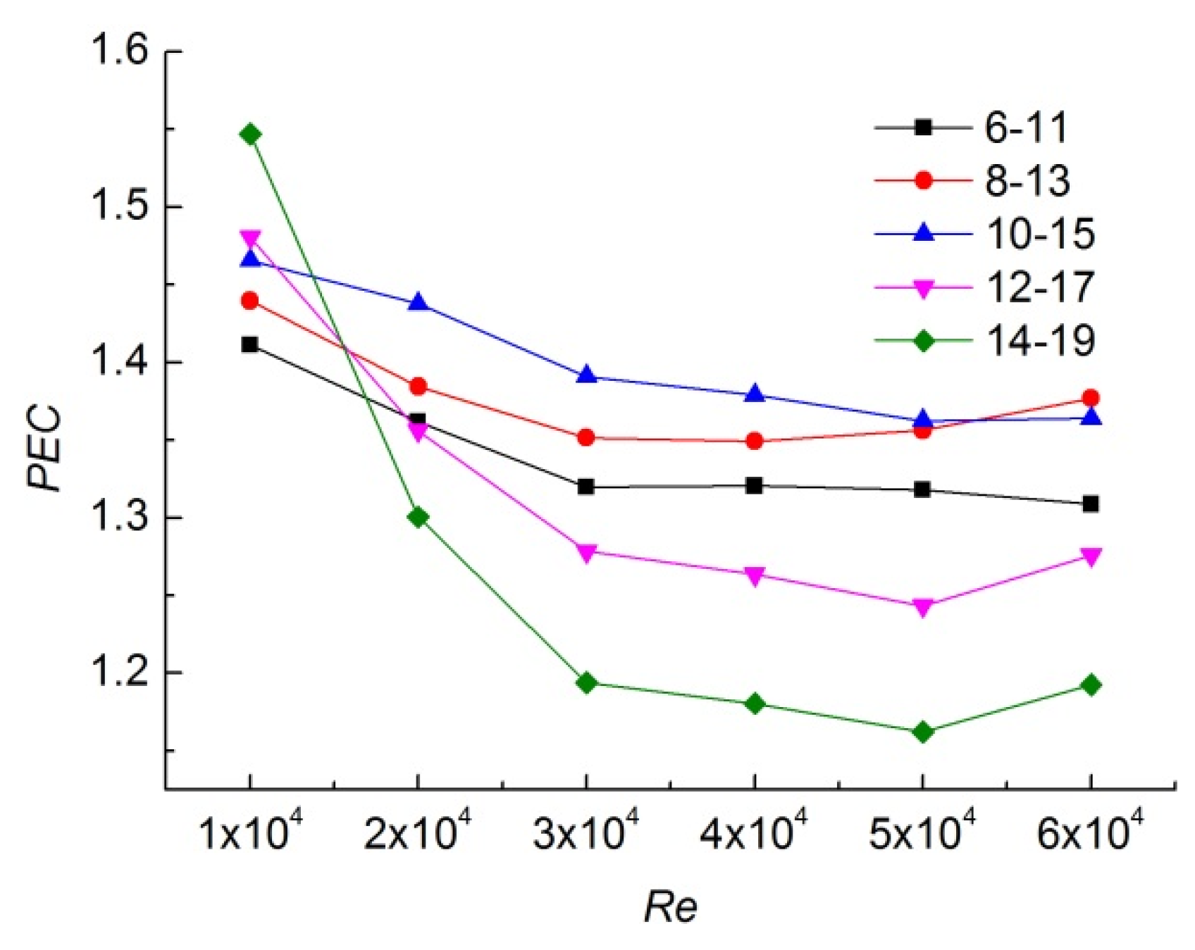
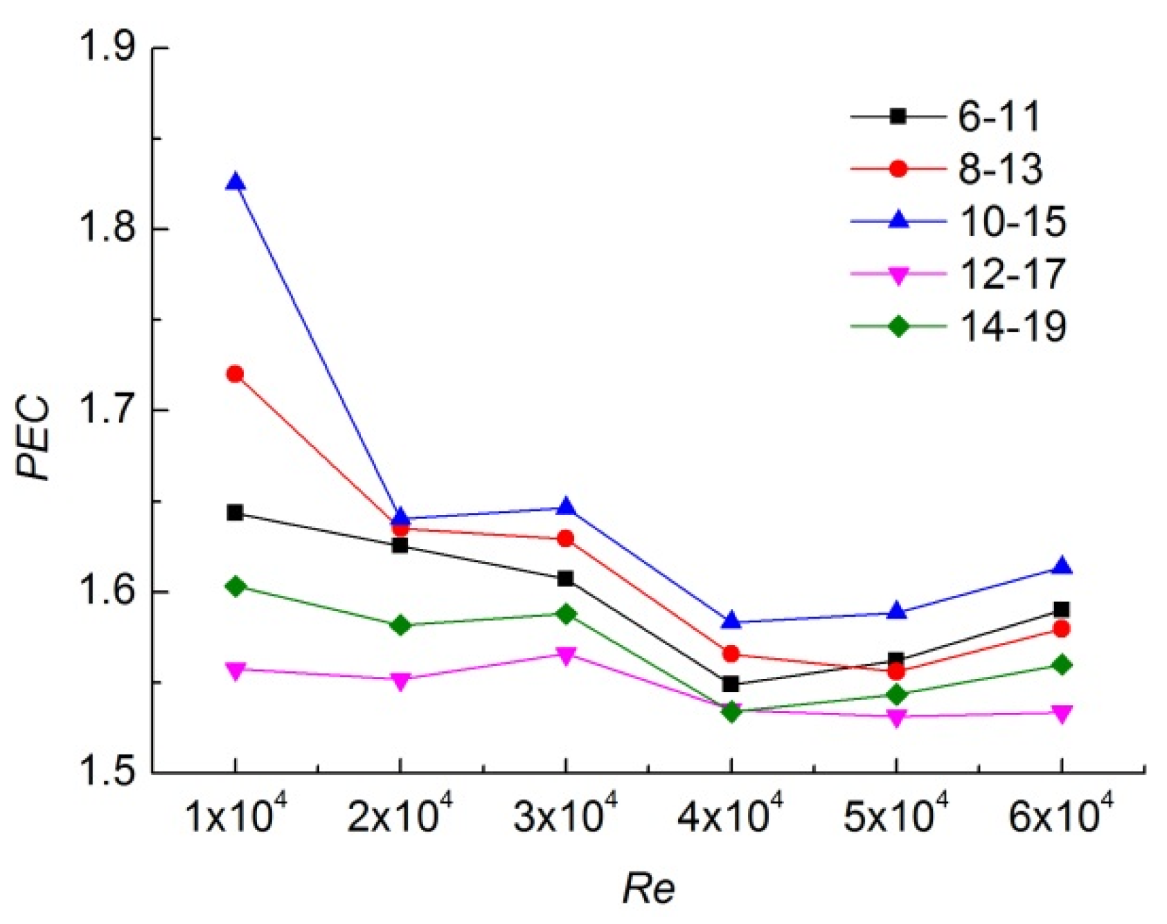
4.2.3. Comparison of Comprehensive Performance of Dimpled Heat Exchange Tube
As shown in
Figure 10 and
Figure 11, the comprehensive heat transfer factor
PEC is greater than 1 in both the tube and shell sides, indicating that the existence of dimple comprehensively enhances the heat transfer capacity of the equipment. With the increase of Re, the turbulence intensity in the tube increases obviously, the disturbance effect caused by cell protrusion and concave was weakened, and the
PEC value of the tube and shell sides gradually decreased. By comparison, it is not difficult to find that although the large-size structure can produce better heat transfer effect, it also produces greater flow resistance. In general, the 8–13 and 10–15 structure in the pipe can better balance the heat transfer effect and flow resistance, and the comprehensive heat transfer capacity is better. In the side of shell, the comprehensive heat transfer factors of the 10–15 dimpled structure are obviously better than other structures studied in this paper. Therefore, considering the
PEC of tube and shell sides comprehensively, the structure 10–15 is the better structure of protrusion and concave cell.
5. Discussion
Numerical calculation was carried out to study the dimpled heat exchange tube. The flow and heat transfer characteristics of the fluid in tube and shell sides of the dimpled tube exchanger were analyzed, and the conclusions are as follows:
(1) The concave dimple in the outer wall creates a dead zone in the flow, which reduces the local heat transfer coefficient to some extent, but also increases the heat transfer area. The vortex formed in the dimple affects the near wall boundary layer and enhances the heat transfer capacity. The inner wall dimples do not produce flow dead zone, and can change the direction of flow velocity in the near wall boundary layer, which destroys the flow state of the fluid in the near wall area in the dimpled tube, and enhances the degree of turbulence. Therefore, the heat transfer performance of both tube side and shell side can be enhanced.
(2) The size of the dimple can affect the effect on the heat transfer ability significantly. In the Reynolds number range of 10,000~60,000, the larger the size of both the concave dimple and the protrusion dimple, the stronger the heat transfer ability, but meanwhile, the larger the resistance.
(3) Non-dimensional performance evaluation criteria showed clear advantage of dimpled tube over the smooth tube. Within the five types of dimple size calculated in this paper, the comprehensive heat transfer factor of 10–15 dimple combination is the largest, up to 1.83, and its comprehensive heat transfer capacity is the strongest. It is worth noting that the combined heat transfer coefficient is better under the condition of low Reynolds number. This indicates that the turbulence intensity increases with the increase of Reynolds number, and the disturbance effect generated by dimple is weakened. The heat transfer capacity should be further optimized by adjusting the cell arrangement, density, and other parameters.
Author Contributions
Conceptualization, overall planning, Z.W.; methodology, modeling, Y.W.; software, numerical calculation, J.Z.; validation, data processing, S.L. and Y.X.; writing—original draft preparation, Y.W.; writing—review and editing, Y.W. and J.Z.; All authors have read and agreed to the published version of the manuscript.
Funding
This research received no external funding.
Institutional Review Board Statement
Not applicable.
Informed Consent Statement
Not applicable.
Data Availability Statement
Not applicable.
Conflicts of Interest
The authors declare no conflict of interest.
Nomenclature
| d | Diameter of inner tube, mm | p | Axial pitch of dimple, mm |
| D | Diameter of outer tube, mm | Pi,out | Outlet pressure of inner tube, MPa |
| DH | Hydraulic diameter, m | Po,out | Outlet pressure of outer tube, MPa |
| E | internal energy | | pressure drop on the flow channel |
| F | Resistance coefficient | PEC | Comprehensive heat transfer factor |
| fh | Resistance coefficient of dimpled tube | Re | Reynolds number |
| fs | Resistance coefficient of smooth tube | T | Temperature, K |
| h | Dimple depth, mm | u | Average velocity, m/s |
| hi | convective heat transfer coefficient | Greek symbols |
| Effective thermal conductivity | | heat conductivity coefficient, |
| L | Length of dimpled tube, mm | | Density of fluid, kg/m3 |
| Nu | Nusselt number | u | Average velocity, m/s |
| Nuh | Nusselt number of dimpled tube | θ | Included angle, degree |
| Nus | Nusselt number of smooth tube | | viscous force component, N |
References
- Liu, S.Y.; Zhang, Y.Y.; Gao, L.; Qiang, J.I. Shell of Heat Transfer Performance Research with Plate-shell Heat Exchanger. Press. Vessel Technol. 2017, 34, 18–24. [Google Scholar]
- Guo, X.X.; Gao, L.; Gai, J.P.; Liu, P. Probing into Influence of Concave-convex Structure Parameters of Corrugated Plate on Heat Transfer Performance. Press. Vessel Technol. 2018, 35, 26–32. [Google Scholar]
- Yan, S.; Fazilati, M.A.; Samani, N.; Ghasemi, H.R.; Toghraie, D.; Nguyen, Q.; Karimipour, A. Energy efficiency optimization of the waste heat recovery system with embedded phase change materials in greenhouses: A thermo-economic-environmental study. J. Energy Storage 2021, 30, 101445. [Google Scholar] [CrossRef]
- Afanasyev, V.N.; Chudnovsky, Y.P.; Leontiev, A.I.; Roganov, P.S. Turbulent flow friction and heat transfer characteristics for spherical cavities on a flat plate. Exp. Therm. Fluid Sci. 1993, 7, 1–8. [Google Scholar] [CrossRef]
- Chudnovsky, Y.; Kozlov, A. Development and Field Trial of Dimpled-Tube Technology for Chemical Industry Process Heaters; Gas Technology Institute: Golden, CO, USA, 2006. [Google Scholar]
- Li, R.; He, Y.-L.; Chu, P.; Lei, Y.-G. Numerical Simul Ation of Dimled Tubes for Heat Transfer Enhancement. J. Eng. Thermophys. 2008, 11, 1947–1949. [Google Scholar]
- Liao, W.; Liu, X.; Zhang, H. Influence of Number of Elliptical Dimples and Their Distribution on Flow and Heat Transfer Performance of Tube. Press. Vessel Technol. 2020, 37, 38–45+67. [Google Scholar]
- Li, B.; Liu, P.; Zheng, N.; Liu, Z. Numerical Simulation of Helically Dimpled Tubes for Convection Heat Transfer and Pressure Drop. J. Eng. Thermophys. 2016, 37, 1261–1267. [Google Scholar]
- Li, M.; Al-Hajri, E.; Ayub, Z.H. Heat transfer and pressure drop characteristics of a single enhanced tube for single phase flow. In Proceedings of the ASME-ATI-UIT 2015 Conference on Thermal Energy Systems: Production, Storage, Utilization and the Environment, Napoli, Italy, 17 May 2015. [Google Scholar]
- Chen, Q.; He, Z.; Liu, J.; Zhu, J. Numerical Simulation of Convection Heat Transfer and Pressure Loss for the Protrusions in the Dimpled Tube. J. Combust. Sci. Technol. 2014, 20, 21–25. [Google Scholar]
- Arasteh, H.; Mashayekhi, R.; Goodarzi, M.; Motaharpour, S.H.; Dahari, M.; Toghraie, D. Heat and fluid flow analysis of metal foam embedded in a double-layered sinusoidal heat sink under local thermal non-equilibrium condition using nanofluid. J. Therm. Anal. Calorim. 2019, 138, 1461–1476. [Google Scholar] [CrossRef]
- Tan, X. Multi-Field Coupled Analysis and Optimization Design of Tube Heat Exchanger in Steam Injection Boiler. Master’s thesis, Northeast Petroleum University, Daqing, China, 2013. [Google Scholar]
- Gnielinski, V. New equations for heat and mass-transfer in turbulent pipe and channel flow. Int. Chem. Eng. 1976, 16, 359–368. [Google Scholar]
- Mashayekhi, R.; Khodabandeh, E.; Akbari, O.A.; Toghraie, D.; Gholami, M. Cfd analysis of thermal and hydrodynamic characteristics of hybrid nanofluid in a new designed sinusoidal double-layered microchannel heat sink. J. Therm. Anal. Calorim. 2018, 134, 2305–2315. [Google Scholar] [CrossRef]
- Burgess, N.K.; Oliveira, M.M.; Ligrani, P.M. Nusselt number behavior on deep dimpled surfaces within a channel. J. Heat Transf. 2003, 125, 11–18. [Google Scholar] [CrossRef]
| Publisher’s Note: MDPI stays neutral with regard to jurisdictional claims in published maps and institutional affiliations. |
© 2022 by the authors. Licensee MDPI, Basel, Switzerland. This article is an open access article distributed under the terms and conditions of the Creative Commons Attribution (CC BY) license (https://creativecommons.org/licenses/by/4.0/).


