Article

Non-Destructive Evaluation of the Quality of Adhesive Joints Using Ultrasound, X-ray, and Feature-Based Data Fusion

by
Elena Jasiūnienė
1,2,*,
Bengisu Yilmaz
1,3,
Damira Smagulova
1,2,
Gawher Ahmad Bhat
1,
Vaidotas Cicėnas
1,
Egidijus Žukauskas
1 and
Liudas Mažeika
1,2
1
Ultrasound Research Institute, Kaunas University of Technology, K. Barsausko Str. 59, LT-51423 Kaunas, Lithuania
2
Department of Electronics Engineering, Kaunas University of Technology, Studentu St. 50, LT-51368 Kaunas, Lithuania
3
Acoustic and Electromagnetic Methods Division, Bundesanstalt für Materialforschung und -prüfung (BAM), 12205 Berlin, Germany
*
Author to whom correspondence should be addressed.
Appl. Sci. 2022, 12(24), 12930; https://doi.org/10.3390/app122412930
Submission received: 14 November 2022 / Revised: 12 December 2022 / Accepted: 14 December 2022 / Published: 16 December 2022
(This article belongs to the Topic Advances in Non-Destructive Testing Methods)

Abstract

:
The aim of this work is to achieve reliable nondestructive evaluation (NDE) of adhesively bonded aerospace components by developing novel multidimensional data fusion techniques, which would combine the information obtained by ultrasonic and X-ray NDE methods. Separately, both NDE techniques have their advantages and limitations. The integration of data obtained from pulse echo immersion ultrasound testing and radiography holds immense potential to help improve the reliability of non-destructive evaluation. In this study, distinctive features obtained from single techniques, traditional ultrasonic pulse echo testing, and radiography, as well as fused images, were investigated and the suitability of these distinctive features and fusion techniques for improving the probability of defect detection was evaluated. For this purpose, aluminum single lap joints with brass inclusions were analyzed using ultrasound pulse echo and radiography techniques. The distinctive features were extracted from the data obtained, and images of features obtained by both techniques were fused together. Different combinations of features and fusion algorithms were investigated, considering the desire to automate data evaluation in the future.

1. Introduction

Recently, adhesive bonding technology has gained considerable attention in various industrial sectors, especially in the aviation, automobile, civil, and marine industries due to the weight reduction of the structure, uniform distribution of mechanical stresses, fairly high strength-to-weight ratio, and ability to join dissimilar materials [1,2,3]. Adhesive joints also provide improved performance of the structure and reduce fuel consumption, which benefits the economic sector. All the advantages and abilities of adhesive joints make this technology the most effective and practical for joining material components, in comparison to traditional bonding techniques, such as riveting, welding, etc. Adhesives are used to bond metal and composite materials to produce different structural components and advanced materials. In the aerospace industry, a substantial number of parts are fabricated using the adhesive bonding of metal and composite materials; however, the manufacturing processes are still unfavorably manual, resulting in various types of defects in the components [4,5]. Factors that can affect the durability of adhesive joints and cause the occurrence of different defects are moisture, poor curing, contamination, a constant structural load, impact force, and others [2,3]. Distinct types of defects, such as delamination, debonding, and weak or kissing bonds, can appear in adhesive joints. These internal defects are extremely critical for structural integrity due to their invisibility and the strong influence on bonding quality. As a result, it becomes difficult to predict the mechanical behavior of the joints in the case of the presence of internal defects [6]. The presence of flaws or discontinuities in the bonded joints should be avoided at all costs for implementing them in critical aerospace components to provide environmental safety, safety of human life and health, and economic benefits.
Recently, many different investigations were carried out using different non-destructive testing (NDT) methods, such as ultrasonic [7], thermography [8,9], eddy current stimulated thermography [10], and others for the inspection of adhesive joints [11,12,13,14]. However, each non-destructive method has its own advantages and limitations upon which the selection of the appropriate method depends. Moreover, the choice of method depends on the structure to be inspected, since most of the methods become impractical after the structure is assembled due to the geometrical complexity of the structure, one-sided access, or even coverage with other layers of functional material [15].
The ultrasonic testing technique is widely and successfully used for the inspection of different structures. Ultrasonic non-destructive testing is advantageous and widely used in identifying and locating defects and can be utilized to evaluate the coherence of the adhesive bonded joints. This method was used by many researchers for the characterization of adhesion quality [16,17]. Adhesive joints can have complex geometry, roughness of the surface, curved surface, or interface layers of the component, which in addition can be not parallel, with varying thicknesses of the materials and their types. All these factors influence the ability of the technique used to detect defects. Zhang et al. [18] investigated the detection of disbonds in multi-layered structures using the laser ultrasonic technique. The technique used was pulse-echo mode for defect detection, and quantitative evaluation was used for defect sizing. Numerical simulations and ultrasonic inspection were also used for the detection of fatigue debonding in composite lap joints in the work of Liu et al. [19]. Liu et al. [20] used numerical and experimental investigations of ultrasonic guided waves. Disbonds were detected because of the variation in the arrival time of the ultrasonic waves. Many other researchers suggest the use of different ultrasonic methods for the detection of interface defects in multi-layered structures, including guided waves, laser ultrasonics, and non-linear ultrasonic evaluation [13,21,22,23,24]. Samaitis et al. proposed a novel approach based on the classical pulse echo technique and machine learning for the classification of weak bonds [25] As a result, ultrasonic techniques are extremely popular and more suitable for the inspection of multi-layered structures for detecting debonding-type defects.
X-ray radiography can offer significant spatial resolution and can investigate the overall thickness of the adhesive. For this reason, X-rays can image and quantify voids over the entire adhesively bonded joint, being an attractive alternative for different inspection techniques [26]. However, in terms of feature detection, contrast is required [27]. Good contrast is achieved when the attenuation coefficient of the X-rays differs significantly in the material inspected in contrast to the defect and/or there is a significant difference in the propagation path length of X-rays in the various materials (defect/non-defect) [28]. Therefore, X-ray radiography is especially good for the detection of volumetric defects, such as large voids [29] or inclusions. In the case of the inspections of thin structures, such as lap joints, where the thickness of the adhesive is small, this poses difficulties in detecting the defects in the joints where thickness along the propagation path of the X-rays is negligibly small (such as in the case of disbonds) and where the attenuation of X-rays in good/bad joints are almost the same.
In addition, it is difficult to detect interface defects with high reliability, since there are many influencing factors depending on the techniques used, samples under investigation, and interface defect types. Therefore, it is significantly important to select and develop a high-performance NDT technique that will satisfy the requirements of testing adhesive joints for high-reliability internal defect detection. The limitation of identifying appropriate NDT techniques has had a considerable influence on the general usage of adhesives, as it is widely assumed that if NDT techniques were reliable enough to ensure bond line integrity, adhesive bonding would be utilized significantly more than it is now.
Given that each non-destructive evaluation technique has varying sensitivity to different defects depending on the component inspected, multiple non-destructive evaluation methods are frequently applied to achieve improved, more reliable, and precise results, demonstrating the need for data fusion of multiple techniques [30]. X. E. Gros published the first book on the applications of NDT data fusion [31]. It provides a variety of research studies reflecting on how multi-sensor NDT is competent to integrate redundant data, distinguishing flaws more precisely and achieving a better signal-to-noise ratio (SNR) [32]. Later, a state-of-the-art survey of NDE data fusion techniques was provided by Liu et al. [33]. Each individual non-destructive method has its own advantages and limitations. For example, ultrasonic waves are best for the detection of delamination or disbond type of defects, while radiography is best for the detection of changes in density. Therefore, the most suitable single NDT method has to be selected according to the requirements to achieve the evaluation goal. Furthermore, it is observed that none of the single NDE techniques can fully characterize the object inspected, and it has its own uncertainty of the obtained result. Moreover, accuracy and reliability requirements are constantly increasing, especially in the field of aerospace and nuclear power industries. Therefore, to meet such requirements, multiple inspection techniques are needed. The fusion of multiple inspections benefits from the advantages of all individual non-destructive inspection methods and diminishes the uncertainty of the measurement result, as well as enhancing the signal. In addition, combining fusion techniques with advanced post-processing algorithms can improve the evaluation results. Fusion can help reduce the uncertainty of the results [33]. Currently, data fusion extends to a wide range of diverse applications [34]. B. Yilmaz et al. illustrated the implementation of the data fusion algorithm in advanced NDT techniques for the identification of defects in single lap composite adhesive joints [35]. Wang et al. have performed terahertz and X-ray image fusion to improve the evaluation of damage of composite materials [36].
In addition, when NDE is applied in industry, there is always a desire to automate the evaluation of data to avoid human factor and increase the probability of detection [37]. Therefore, one of the objectives of this work is to develop the process of determination and extraction of features for different inspection results for their further fusion, as well as to create a fusion algorithm to develop a reliable NDT technique for the investigation of multi-layered structures with bonding defects.
The aim of this work is to achieve reliable non-destructive evaluation (NDE) of adhesively bonded aerospace components by developing novel multidimensional data fusion techniques, which would combine the information obtained by ultrasonic and X-ray NDE methods. Separately, both NDE techniques have their advantages and limitations. For instance, ultrasonic NDE methods are sensitive to elastic properties and density and are good at detecting planar defects, such as lack of bonding/delamination; however, they may suffer from attenuation or diffraction. X-rays are very sensitive to changes in density and volumetric defects, but their performance on planar defects is limited. The integration of data obtained from pulse-echo immersion ultrasound testing and radiography holds immense potential for helping to improve the reliability of non-destructive evaluation. The objective of this investigation was to study and compare distinctive features obtained from single techniques, traditional ultrasonic pulse echo testing and radiography, and fused images, as well as to evaluate the suitability of different features and fusion techniques to improve the probability of defect detection.
On the basis of the data fusion algorithms, this article presents feature-based image fusion of ultrasonic and radiography testing. For this purpose, single lap aluminum joints with brass inclusions were analyzed using ultrasound pulse echo and radiography techniques. Then, different features were extracted from the obtained data. Then, images of the features of both techniques were fused together. Different combinations of features and fusion algorithms were investigated considering the desire to automate data evaluation in the future. The discussion of the qualitative and quantitative analysis obtained is presented in the discussion section, followed by the conclusions.

2. Materials and Methods

The workflow of the NDE of the adhesive joints using ultrasonic, radiography, and data fusion of both is presented in Figure 1. It consists of the following steps:
  • Data acquisition (using ultrasonic and radiography techniques);
  • Modelling of ultrasonic signal to determine the zone of interest in ultrasonic A-scans;
  • Feature extraction;
  • Feature-based data fusion;
  • Evaluation of results.

2.1. Sample Description

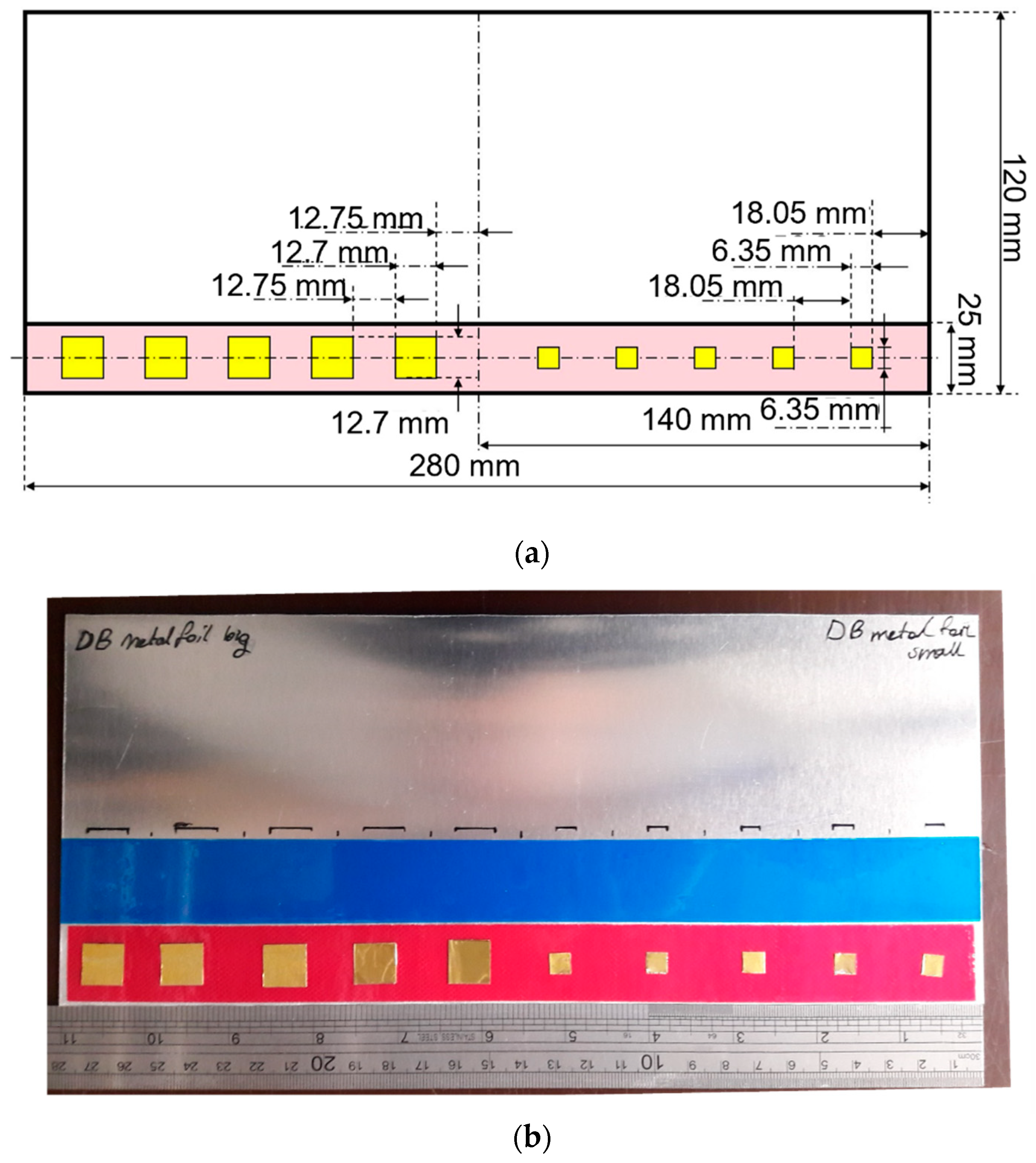
The aluminum–epoxy adhesive single lap joints were manufactured by COTESA GmBH, Germany. For aluminum–epoxy joints, adherend was selected as 1.6 mm sheet 2024 aerospace aluminum alloy. The aluminum plate shown in Figure 2 had dimensions of 280 × 215 × 1.6 mm. A 3M Scotch-Weld AF 163-K red structural adhesive epoxy film with a thickness of 0.16 mm was used as adhesive. The lap joint was 25 mm wide. Following the necessary surface preparation, the epoxy film was placed on the adherend. There were 10 brass inclusions placed on the adhesive of different dimensions—5 large inclusions with a size of 12.7 mm, while the space between the consecutive defects is approximately 12.75 mm. On the other side, five smaller brass inclusions of size 6.35 mm were equally distributed with the space between the consecutive defects, approx. 18.05 mm. In further investigations, four out of five smaller defects were investigated because the holder was shadowing one of the defects. The schematics of the sample with the size and position of the defects is shown below in Figure 2. The thickness of the double-sided brass inclusion was 0.05 mm.

2.2. Investigation Techniques

The aluminum single lap joint was examined using pulse-echo immersion ultrasonic and radiographic testing, and then the fusion of the results obtained by these two techniques was performed.

2.2.1. Immersion Ultrasonic Testing

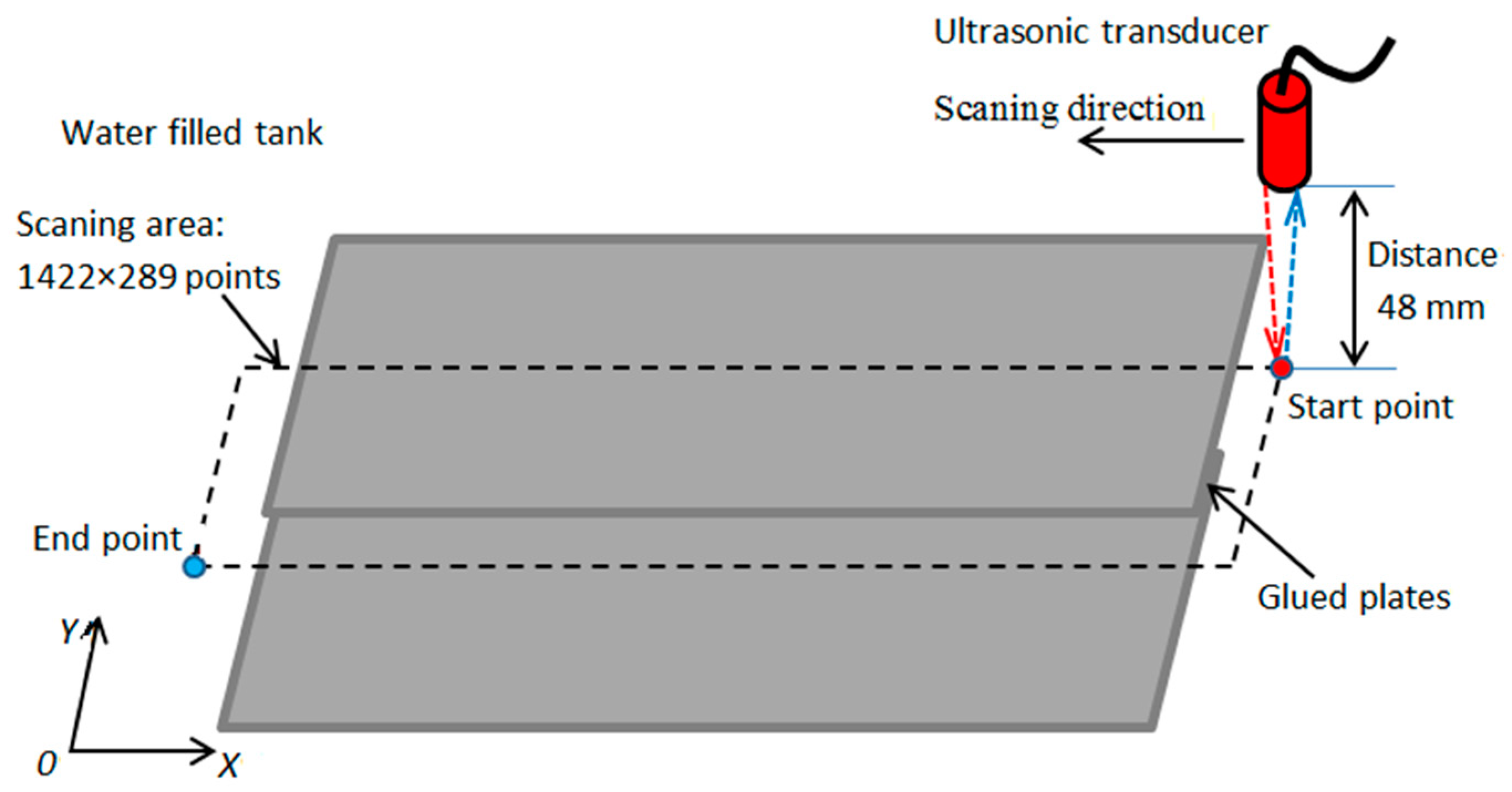
The investigation of the aluminum adhesive lap joint with brass inclusion was carried out in an immersion tank using an Olympus V328-SU focused transducer with a central frequency of 15 MHz and a diameter of 10 mm. The far-field distance between the transducer and the sample top surface was kept fixed at 48 mm. The transducer was positioned in such a way that the emitted beam was perpendicular to the sample surface. Investigation of the single-lap joint was carried out on the entire bonded region with a 0.2 mm scan step and 1422 × 289 scanning points. The schematics of the ultrasonic pulse-echo immersion testing is shown in Figure 3.

2.2.2. Radiographic Testing

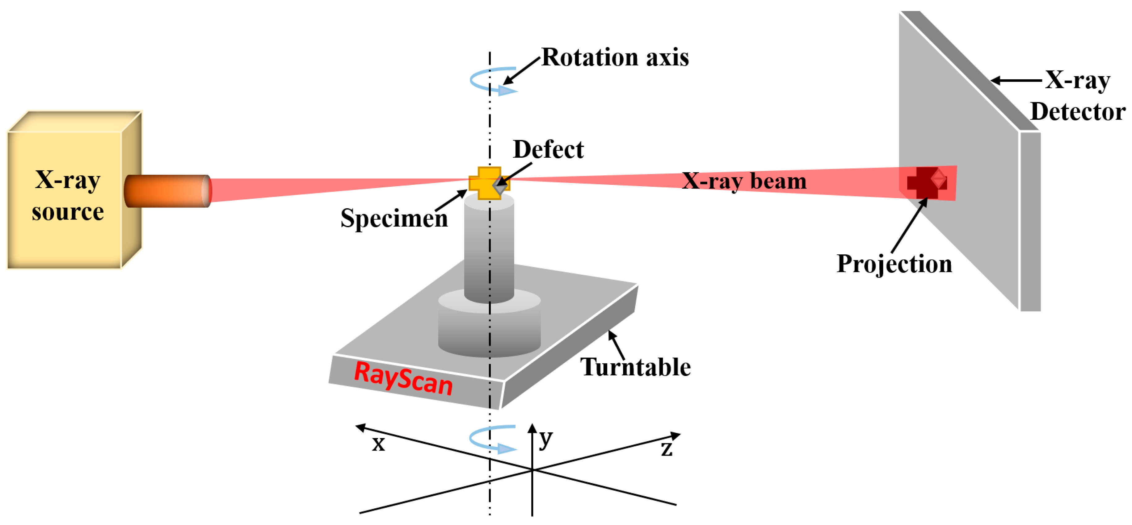
The adhesive bonded single lap joint was scanned using radiography as well. For this, the Rayscan 3D CT system was used. In this investigation, a 225 kV microfocus tube was used. The detector of the computed tomography system was a 2048 × 2048 flat matrix detector equipped with a scintillator. The schematic of the experimental set-up of the radiographic testing is shown in Figure 4. During the measurements, an X-ray source irradiated the sample at a voltage of 150 kV and a current of 300 µA with the cone beam and a 2D image was recorded at the detector with the integration time of 1500 ms. The focal spot was 47 µm, while the voxel size was 145 µm.

2.3. Ultrasonic Signal Modelling

Modelling was performed to study the behaviour of ultrasonic waves propagating through the layers of adhesively bonded aluminum to aluminum with brass inclusion defects located between metal and adhesive, as well as to study their propagation and reflection paths from the sample interfaces to determine time instances of each for determination of gates to be used when selecting the part of the signal of interest for determination of features. According to our previous work [3], it was discovered that the analysis of multiple interface reflections improves the probability of defect detection. Therefore, time instances of ultrasonic impulses that correspond to multiple interface reflections were studied in this part.
The model that complies with the sample under investigation was modelled in MatLab software. Sample and medium characteristics are presented in Table 1. The distance between the focused transducer and the sample surface was 48 mm.
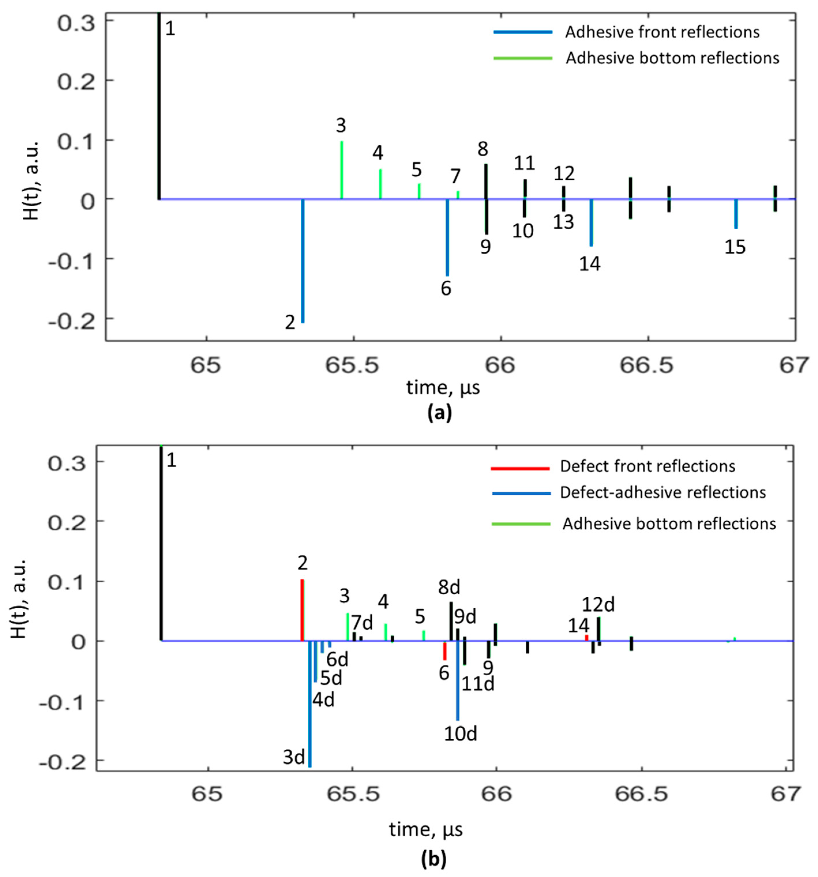
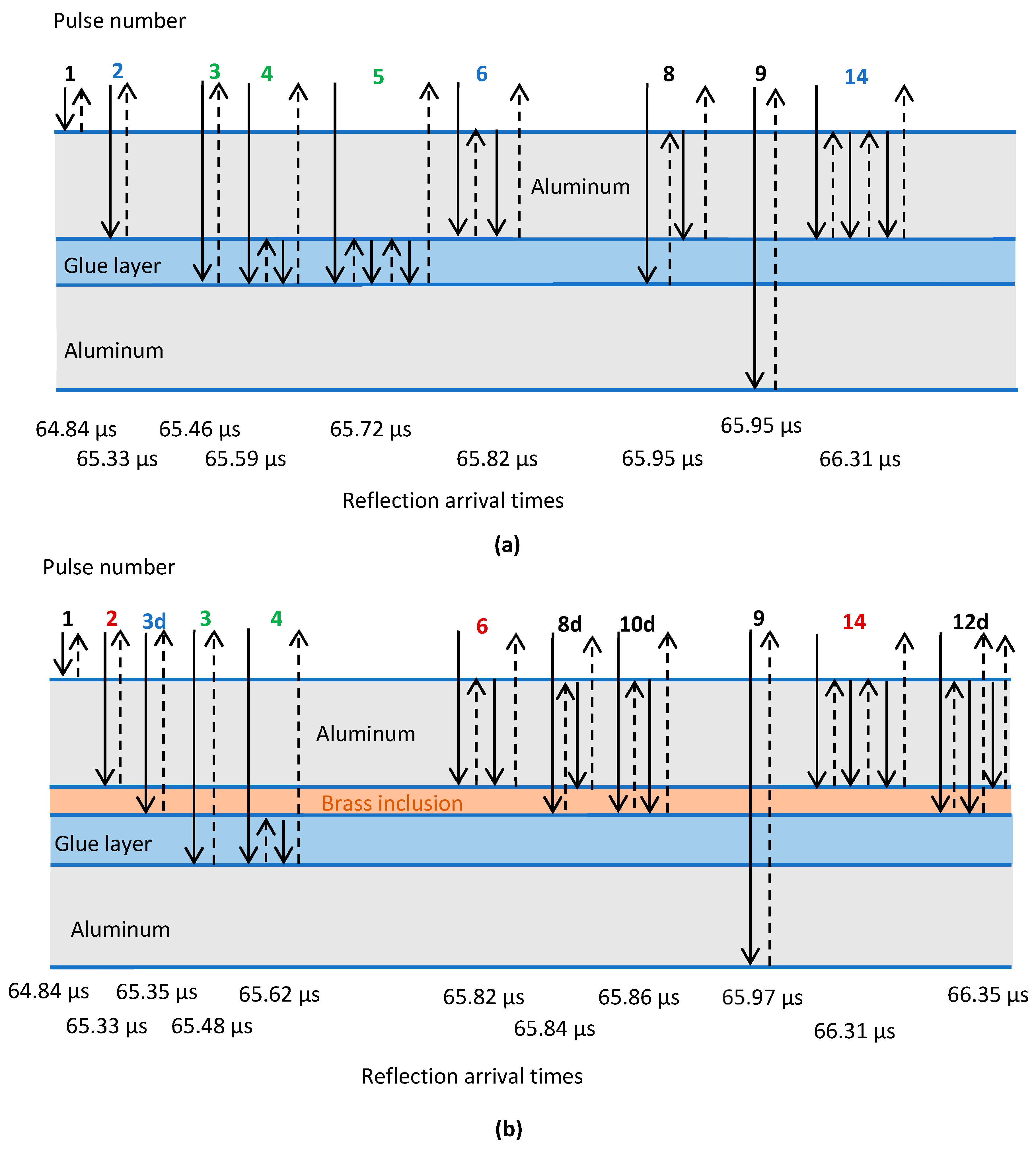
As a result of modelling, pulse responses of each reflection from the structure boundary were obtained. Images with impulse plots characterizing the arrival time of each signal reflected from different sample boundaries with and without defects are presented below in Figure 5. Additionally, in Figure 6 the propagation paths of the ultrasonic wave for each signal impulse reflected from the sample interfaces, as well as their time moments for the non-defective and defective options, are presented.
According to obtained plots of impulses, the time moments of multiple reflected signals from the sample interfaces coincided: aluminum–adhesive interface (impulses 2, 5, 7) in the case of the sample without defect and aluminum–brass inclusion (impulses 2, 5, 7) for the sample with defect. In addition, for the sample with defect, there was a change in phase, for multiple interface reflections: aluminum–brass inclusion, which differed from the option of sample without defect. In addition, additional wave reflections from the brass inclusion bottom appear and overlap with other reflections from the boundaries.
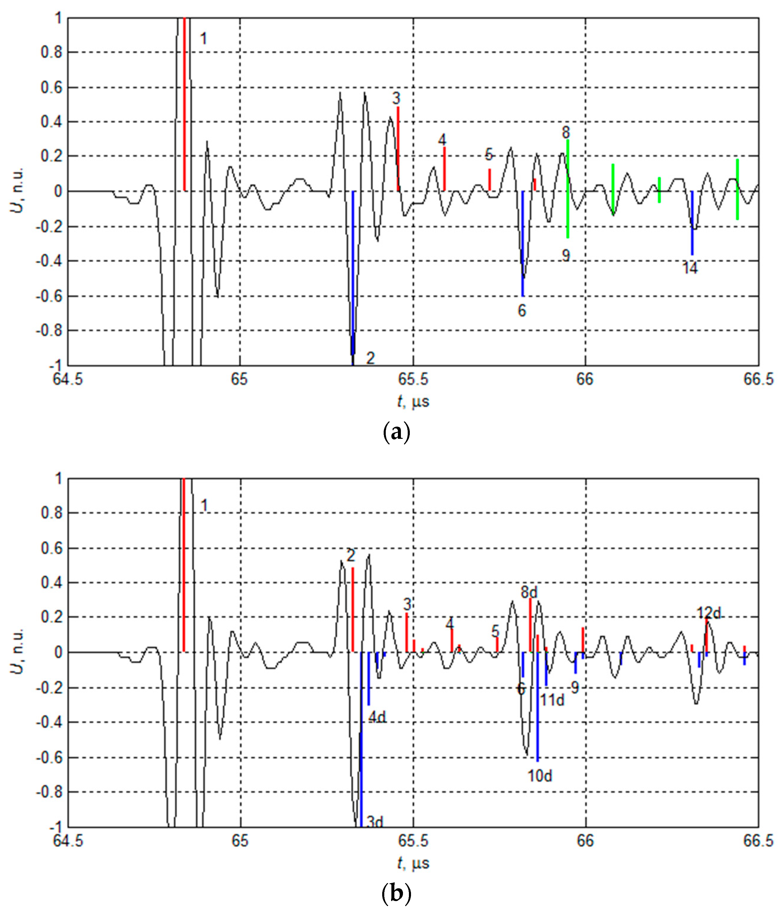
To obtain time diagrams of the signals propagating in the investigated structure, the convolution of the pulse response and the excitation signal was performed. The excitation signal was a sine burst of 15 MHz frequency 2 periods with a Gaussian envelope. The time diagrams obtained in defect-free and defective objects are presented in Figure 7a,b, respectively. In the case of defect-free objects, individual pulses reflected from different material boundaries were easily distinguished. Pulse no.1 was surface reflection, pulse no.2 was reflection obtained from aluminum–adhesive boundary, pulses no.3–5 were multiple reflections in adhesive layer, and pulse no.6 was the second reflection from aluminum–adhesive boundary. However, in the case of a defective sample, the analysis of the reflected signals (Figure 7b) was much more complicated: pulse no.1 was surface reflection, while pulse no.2 was the result of interference of pulses reflected from aluminum–brass, brass–adhesive, and adhesive–aluminum boundaries (see Figure 5b pulses 2–7). It can be observed that it was impossible to separate signals reflected from separate boundaries. However, there is a particularly important feature that allows us to determine the presence of the defect—the phases of second reflections were opposites. In case of defect-free sample wave, it reflected from aluminum–adhesive boundary, i.e., from material with lower acoustic impedance. In this case, the wave was reflected with opposite phase. In case of defective sample ultrasonic wave, it reflected from aluminum–brass boundary, i.e., from material with higher acoustic impedance. In this case, the wave is reflected with the same phase.
In terms of the impulse response, Figure 7 presents the main signals reflected from the different layers of the sample, whereas in Figure 8 the experimental data are presented with an overlayed theoretically calculated impulse response. Red spikes denote pulses with positive phase, blue with negative, and green is the combination of two pulses with the same flight time but opposite phases, as can be seen in Figure 8. The measured data were normalized according to the first plate backwall and adhesive interface reflection.
According to the analysis of impulses and waves propagation paths, most the information of the defect was from time moment of wave reflection from the aluminum–defect interface. From the previous study [3], analysis of multiple reflections increases the probability of defect detection. Therefore, time intervals starting from the moment of aluminum–defect reflection to the next multiple reflections were used as a feature for setting the gates in the step of data fusion.

2.4. Data Fusion

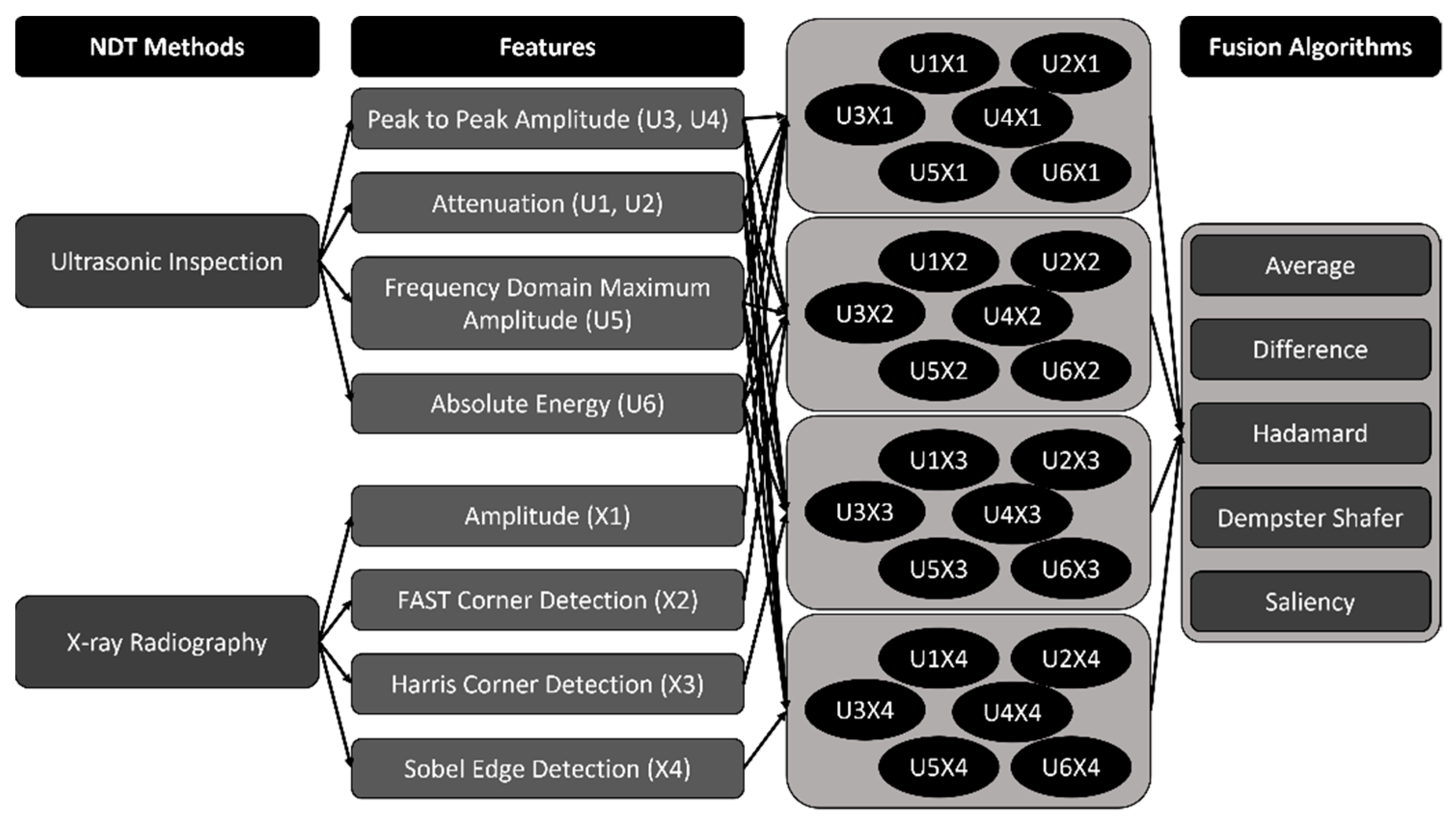
It is not always possible to extract all relevant data from a single sensor and detect defects in a component. Often, there is a need to have information from two or more sensors/techniques for the better evaluation of the results. Data fusion can be used at various levels: pixel, signal, feature level [38]. In this work, feature-based fusion was chosen for the fusion of ultrasonic and radiographic testing results. In Figure 9, the workflow of the procedures applied is shown. Using two different measurement techniques, the different features were extracted. Then, different combinations of ultrasonic and radiographic features were supplied to a variety of fusion algorithms to test the suitability of features and fusion algorithms for automation of the defect detection in the future.

2.4.1. Preparation of Data for Data Fusion

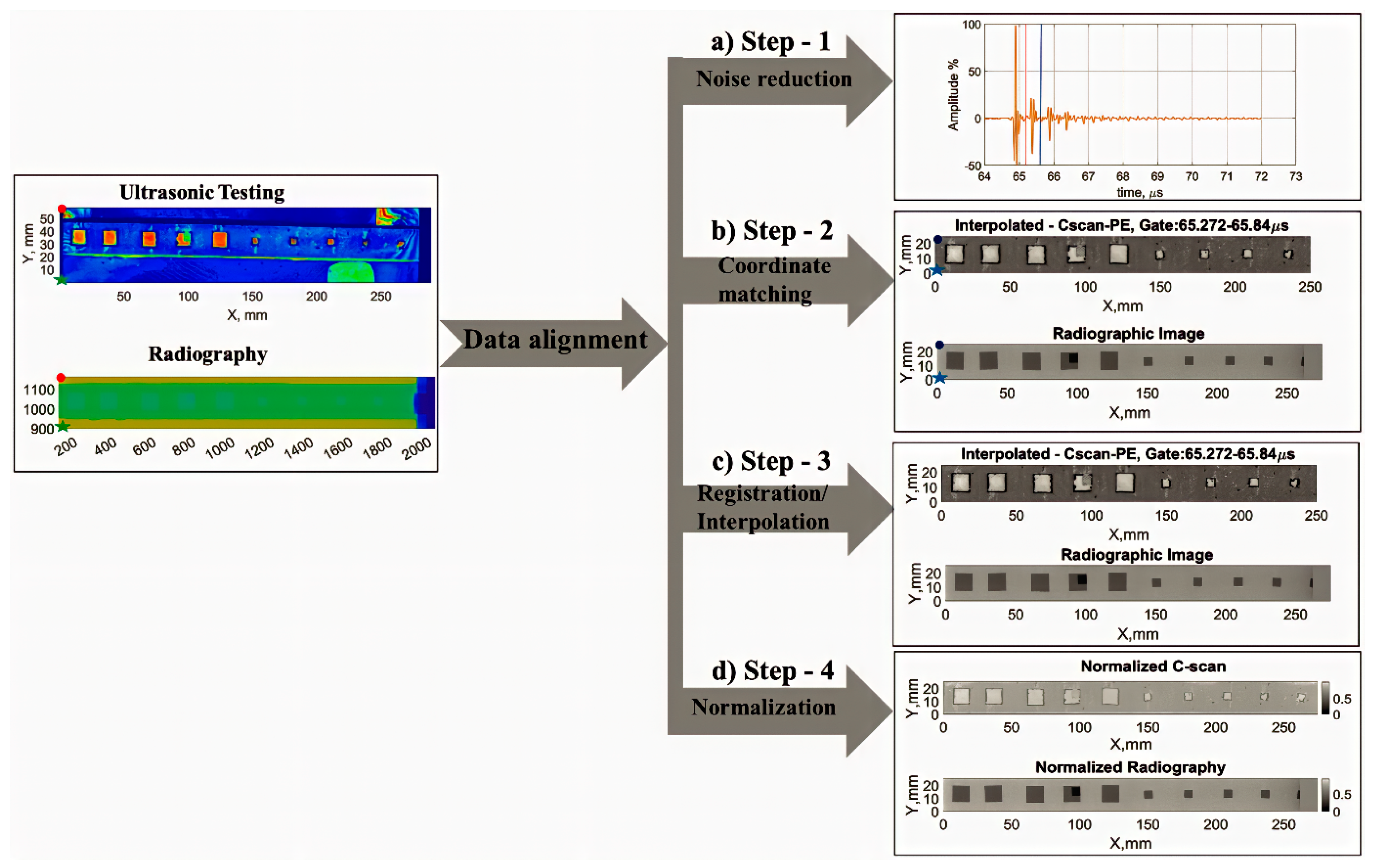
Before the fusion, the data needed to be prepared, undergoing several steps of preparation: noise reduction, coordinate matching, registration/interpolation, and normalization (see Figure 10). It was important to align the data obtained from different NDE techniques before the implementation of the data fusion. The raw data obtained from the experimental investigation of the single lap adhesive joint using ultrasonic and radiographic testing were aligned based on different parameters, such as noise removal, coordinate matching, interpolation, and normalization. The multi-step algorithm describing the pre-processing on the experimental data of two different techniques of non-destructive testing is shown in Figure 10.
The evaluation of bonding quality in the aluminum single-lap joint was conducted using separate experimental set-ups, and as such the data obtained had a local coordinate system. To perform data fusion on such varied systems, the coordinates of the experimental data from the investigation had to be matched. The data were aligned with the position of the bonding edges of the adhesive joint to match the coordinates. The data from immersion ultrasonic inspection had to be flipped to match the radiographic testing data and further interpolated to match the coordinates of the newly registered data shown. Finally, the values of the radiographic and ultrasonic data were normalized using linear scaling (0 to 1).

2.4.2. Selection of Features

Several distinctive features for both the ultrasonic and radiographic experimental data were used as input for data fusion. Previous work on the reliability of detecting debonding defects with ultrasonic techniques in adhesive joints showed that in addition to the amplitude of the ultrasonic echo, the attenuation and the amplitude in frequency domain play important roles in the defect contrast [2], allowing higher probability of defect detection. Therefore, in this study, in addition to the peak-to-peak amplitude, we also selected signal attenuation, frequency domain maximum amplitude, and absolute energy as features of the ultrasonic inspection results, as shown in Table 2. The features are extracted by applying the specified formula to 3D ultrasonic data (x, y, t), hence the dimensions are reduced to 2D (x, y). On the other hand, we applied 2D image processing techniques to obtain 2D (x, y) X-ray radiography results to create additional features, namely, FAST (features from accelerated segment test), Harris corner detection, and Sobel edge detection.

2.4.3. Data Fusion Algorithms

The main purposes of employing data fusion in different testing environmental conditions are to reduce the probability of error and improve the reliability of defect detection. A wide range of fusion algorithms can be used for the fusion of two-dimensional data, including wavelet-based combinations, Bayesian theory, Kalman filter, Dempster Shafer [39], and artificial neural networks [40]. This piece of work focused on the application of multiple feature-based fusion algorithms, namely averaging, difference, Hadamard, Dempster Shafer rule of combination, and pyramid fusion with saliency detection.
Simplest of all fusion algorithms, average, is performed at a pixel level—the average of feature matrices obtained from two sources is calculated. On the other hand, difference fusion is estimated based on the feature value difference on each pixel value from different NDT results. Hadamard fusion is calculated with the pixel-wise multiplication of same-size matrices.
The Dempster–Shafer theory was initially proposed by Arthur Dempster in the 1960s for reasoning uncertainties and later developed by Glenn Shafer in the 1970s [41,42]. The Dempster–Shafer (DS) theory is applicable to instances wherein non-probability uncertainty is evident. The DS evidence theory is based on mass, belief, and plausibility functions. The DS rule of combination is used to calculate the unique evidence mass (m) for the hypothesis by incorporating the evidence masses (m1, m2). In this study, the hypothesis was categorized as positive in case of defects and negative in case of non-defects.
Saliency detection is a hot topic that has recently piqued the interest of researchers from a wide range of disciplines. In our investigation, source images of ultrasonic and radiographic testing were decomposed into approximation base layer coefficients and detail layer coefficients using the multi-scale decomposition algorithm [43]. The salient features of the X-ray and ultrasonic features are extracted using a basic saliency map detection algorithm [44].
The data fusion algorithms used, their short descriptions, and mathematical formulas are provided in Table 3.

3. Results

The aluminum adhesive lap joint with brass inclusions of varied sizes has been investigated using the techniques described above: ultrasonic immersion testing and radiography.

3.1. Features

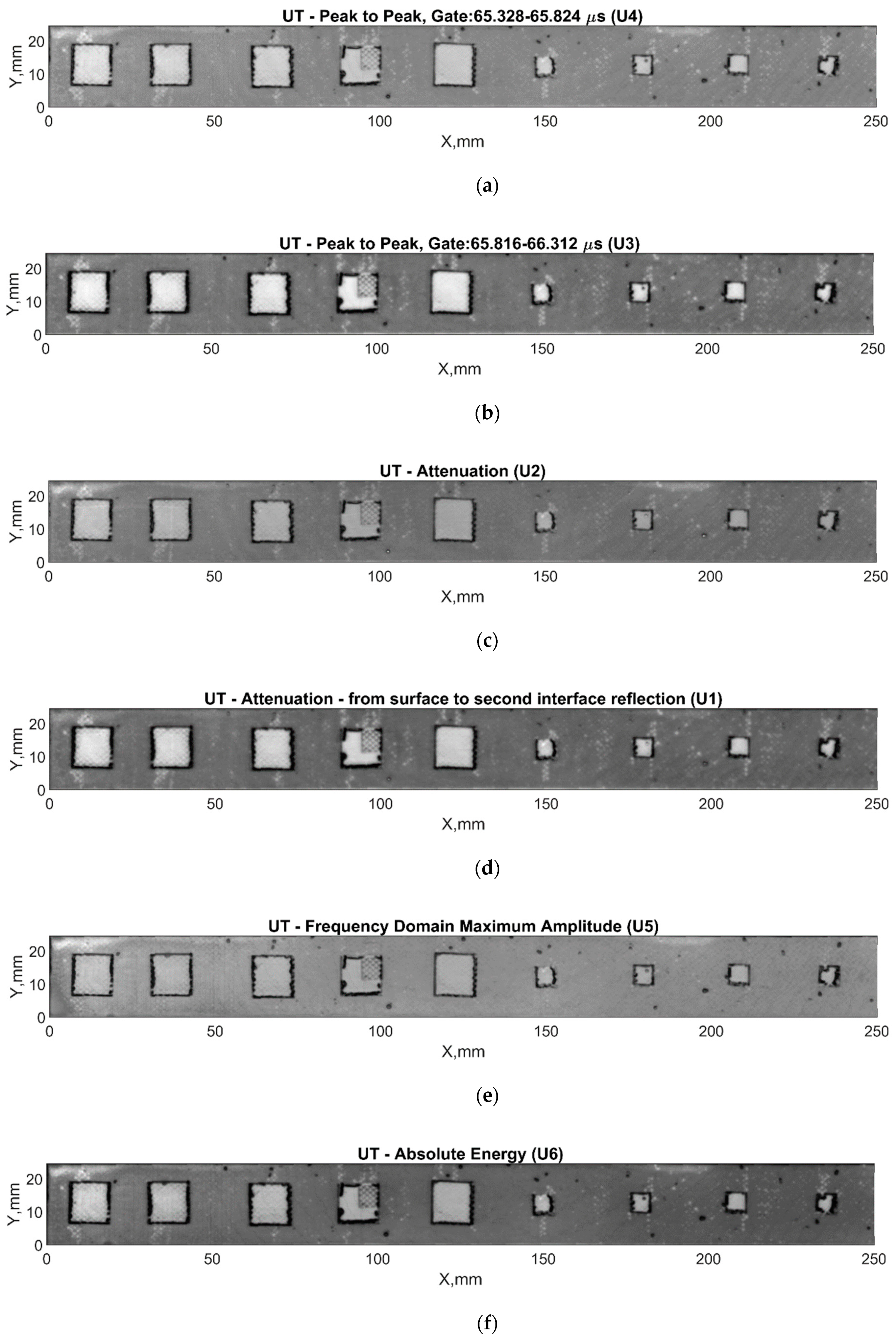
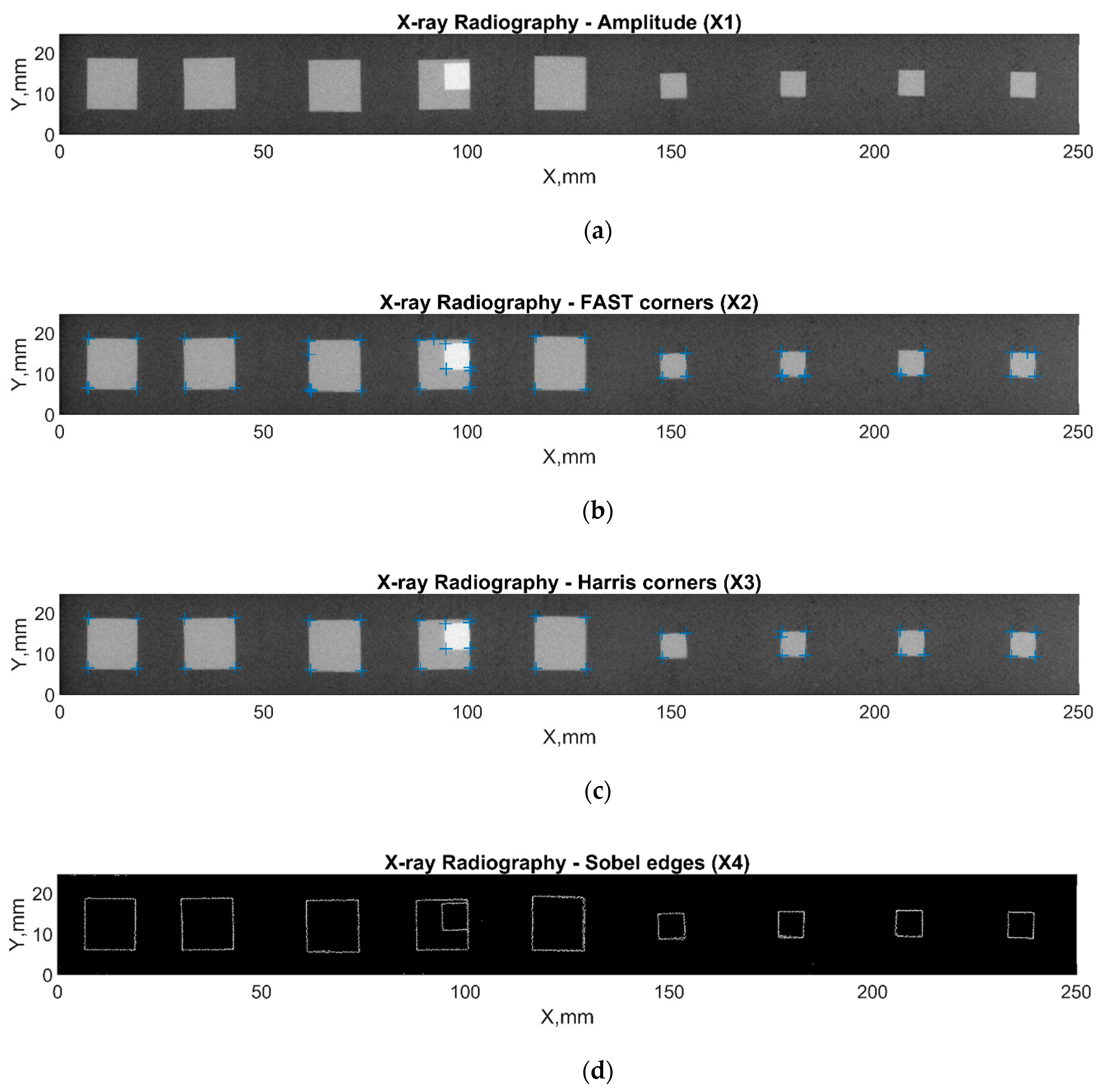
From the results obtained, different feature images were extracted to be used later for data fusion. The selection of features was based on our previous investigations of adhesive joints [35]. The features described in the previous sections were used. In Figure 11, images for the following ultrasonic features are presented: peak-to-peak amplitude, attenuation, and frequency. In the case of radiographic testing, the following features were analyzed (see Figure 12): amplitude, FAST corners, Harris corners, Sobel edges.

3.2. Data Fusion

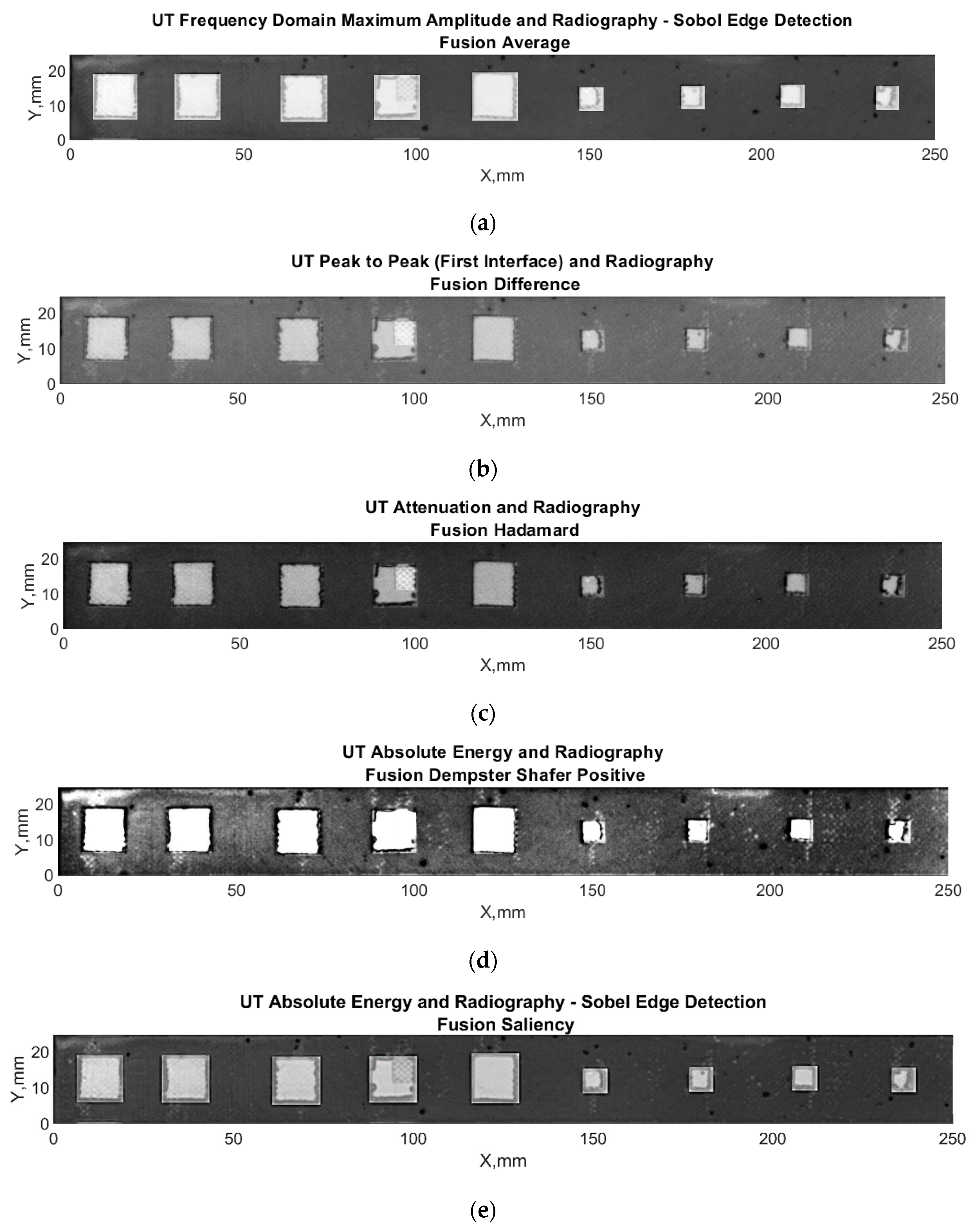
Data fusion was applied to the combination of ultrasonic and X-ray-based features, as shown in Table 2, using five fusion algorithms. The selected combinations of the results are presented in Figure 13.

4. Comparison of Different Techniques and Discussion

The features and fused images of the X-ray and ultrasonic testing were analyzed using the response operating characteristics (ROC) curves and the area under curve (AUC) values. The photo of the sample with defects before bonding, as shown in Figure 2, was used as the reference image to evaluate the quality of the fusion results: the form and position of the defects was extracted from this photo to evaluate the accuracy of the features and fused images, in terms of inclusion-type defect recognition. First, registration (including interpolation and normalization) and coordinate matching have been applied to the image, considering the fusion data size. Then, the defect positions have been determined via postprocessing of the edge detection algorithm. The fusion results of each defect have been evaluated separately, considering this image. The results are evaluated using the area under curve estimations of response operating characteristic curves.
An arbitrary reference matrix was constructed based on the known location of the defects, with defected regions given the value 1 and perfectly bonded regions—0. By knowing the position of the defects, it was possible to create a mathematical formulation of a defect and a non-defect matrix that was used for comparing techniques. Every reference matrix was converted to binary so that the ROC curve could be used for the evaluation. Histogram-based segmentation was carried out. The segmented pixels in the matrix were then categorized into one of four categories: true positive (TP) indicates the presence of a defect in the defect position, false positive (FP) indicates the defect in a perfect bond region, true negative (TN) represents the defect-free good bond region, and false negative (FN) represents the defect-free position. The true positive and false positive rates for each segmented matrix were calculated in accordance with specific and sensitivity information and could be mathematically expressed as follows:
R T P = N T P N T P + N F N   ( X )
R F P = N F P N F P + N T N   ( X )
where RTP is the true positive rate, RFP is the false positive rate, NTP is the number of true positives, NFN is the number of false negatives, NFP is the number of false positives, and NTN is the number of true negatives.
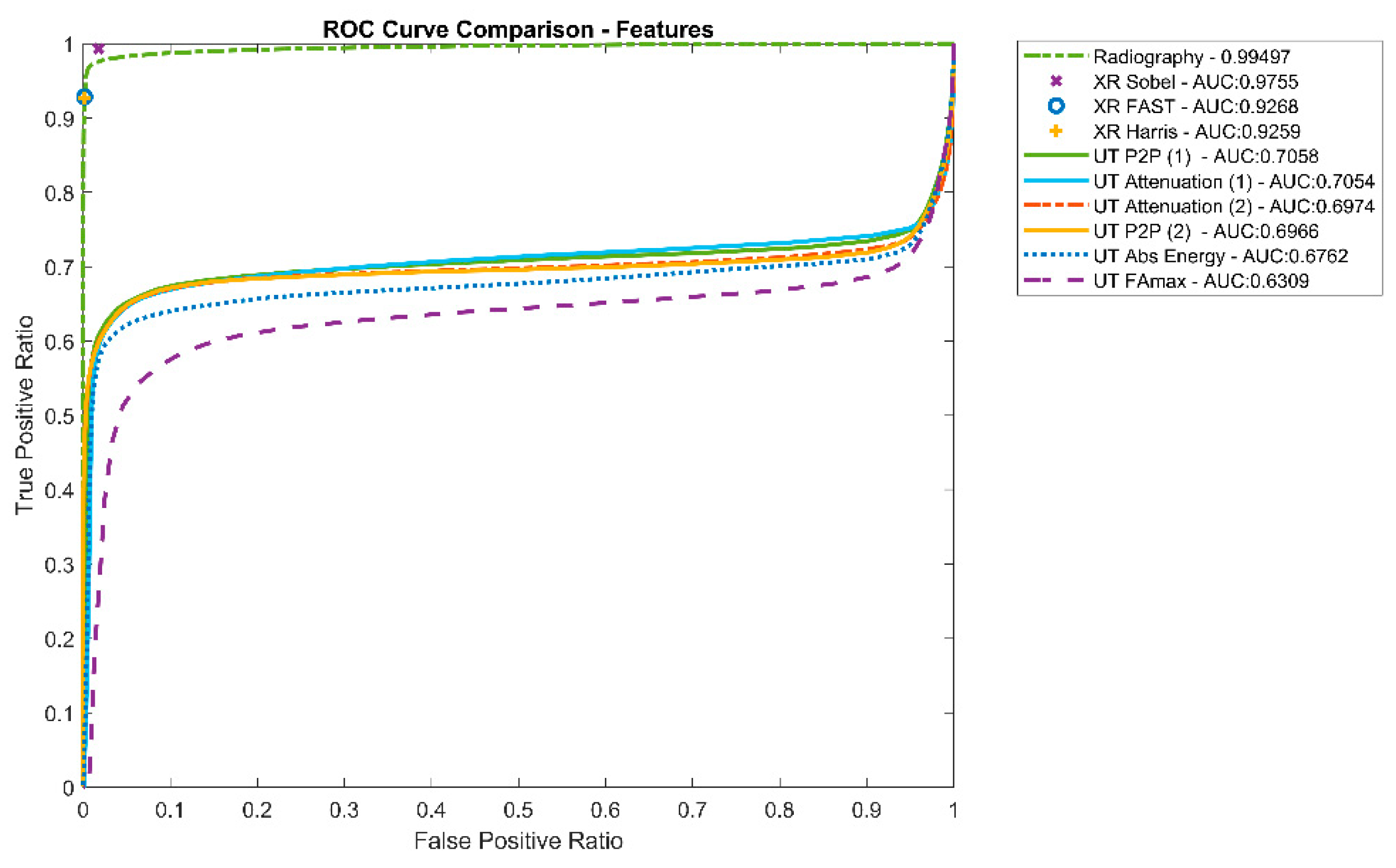
Figure 14 shows the average performance of the distinctive features, according to the ROC curves and AUC values. It could be observed that in the case of the inclusion type of the defect, all features extracted from radiography data perform better according to the ROC curves and the AUC values.
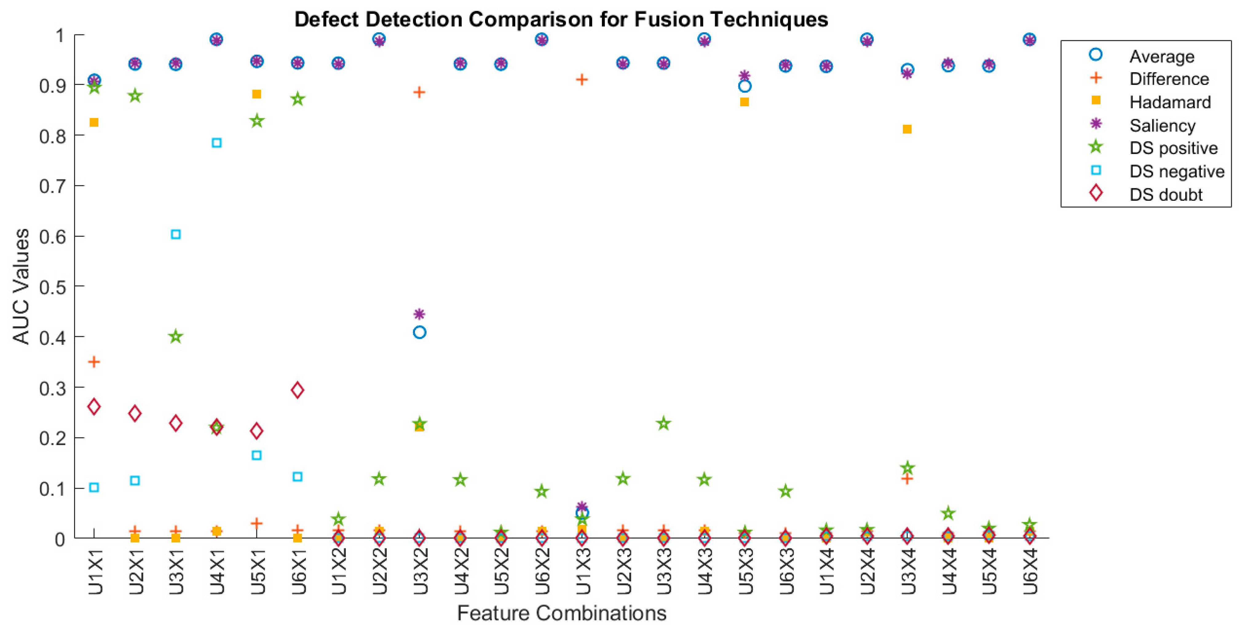
The fused results were evaluated with distinctive features that were extracted from the results obtained by different techniques and are presented in Figure 15. The analysis of the results shows that from the fusion algorithms used, simple average and saliency gave the best results in the case of a brass inclusion type of defect. It is surprising that the performance of the Hadamard and Dempster–Shafer algorithms was much worse than expected. For ultrasonic features in terms of suitability for fusion, the best performance was achieved when using following features: ultrasonic signal attenuation (U2), peak-to-peak (U4), and absolute energy (U6). Although all radiographic features performed similarly, the final result was more influenced by the fusion algorithm.
The AUC values for each feature are given in Figure 14, and the AUC values presented for each feature and fusion combination are presented in Figure 15. The combination of features refers to the values given in Figure 9. It could be observed that fusion with averaging and saliency performs best in almost all fusion combinations. Additionally, the defect detection performance of radiographic features (except for the radiography amplitude feature) can be improved by the fusion application of the best performing ultrasonic signals (U2, U4, U6).
In addition, the visual examination of the fusion results presented in Figure 13 reveals that fused results give additional information about the structure. It is obvious that radiography reveals the inclusion type defects very well; however, ultrasonic results provide additional information about the structure—additional disbond regions around the edges of the inclusions are visible.

5. Conclusions

The purpose of this investigation was to develop a feature-based data fusion technique to improve the probability of defect detection in the adhesive lap joints. Data were experimentally obtained using two common NDE techniques: ultrasonic pulse-echo and radiography. For this investigation, single lap adhesive-bonded aluminum joint with different sizes of brass inclusions were used. For the selection of the zone of interest in ultrasonic A-scans, theoretical analysis and modelling of impulse responses from interfaces in the sample were performed and multiple reflections inside the sample were analyzed, as well as different propagation paths. The modelling results were confirmed by experimental investigations of the propagation of ultrasonic waves. For the analysis, several distinctive features were extracted from the experimental ultrasonic and radiographic data and used as inputs for the data fusion. The comparison of extracted features shows that, at least in the case of the inclusion type of defect, the most promising features giving the highest contrast in terms of the defect/non-defect region from ultrasonic images are signal attenuation, peak-to-peak amplitude, and absolute energy; however, other features, especially frequency domain related, should not be disregarded. Feature-based image fusion of both techniques was also applied and evaluated using different data fusion algorithms. This helps to overcome the limitation of multimodal imaging and improves the prediction possibility and reconstruction of the missing information from the images of the single techniques. The fused image i provides intricate details of the defects in the sample on a finer scale. Although radiographic image contributes to the detection of the inclusion type of defect the most, the ultrasonic image provides extra information about additional types of defects, such as disbonds around the edges of the inclusions, which are not visible in the radiographic images. Of the fusion algorithms used, the best performance was achieved using average and saliency algorithms—AUC values of more than 0.99 are achieved.

Author Contributions

Conceptualization, E.J.; methodology, E.J.; software, B.Y., L.M., V.C. and G.A.B.; validation, E.J.; formal analysis, B.Y, D.S. and G.A.B.; investigation, E.J., D.S., E.Ž. and G.A.B.; resources, L.M. and E.J.; data curation, B.Y.; writing—original draft preparation, G.A.B. and D.S.; writing—review and editing, E.J., B.Y., V.C. and E.Ž.; visualization, B.Y., D.S., V.C., E.Ž. and G.A.B.; supervision, E.J.; project administration, E.J.; funding acquisition, E.J., L.M., V.C., E.Ž., D.S. and B.Y. All authors have read and agreed to the published version of the manuscript.

Funding

This research has received funding from the Research Council of Lithuania (LMTLT), agreement No S-MIP-22-5 and agreement No S-PD-22-25.

Institutional Review Board Statement

Not applicable.

Informed Consent Statement

Not applicable.

Data Availability Statement

The data presented in this study are available on request from the corresponding author.

Conflicts of Interest

The authors declare no conflict of interest.

References

  1. Tserpes, K.; Sioutis, I.; Floros, G.; Moutsompegka, E. Numerical simulation of debonding of a composite-to-metal adhesive joint subjected to centrifugal load. Eng. Fail. Anal. 2022, 136, 106131. [Google Scholar] [CrossRef]
  2. Yilmaz, B.; Smagulova, D.; Jasiuniene, E. NDT and E International Model-assisted reliability assessment for adhesive bonding quality evaluation with ultrasonic NDT. NDT E Int. 2022, 126, 102596. [Google Scholar] [CrossRef]
  3. Smagulova, D.; Mazeika, L.; Jasiuniene, E. Novel Processing Algorithm to Improve Detectability of Disbonds in Adhesive Dissimilar Material Joints. Sensors 2021, 21, 3048. [Google Scholar] [CrossRef] [PubMed]
  4. Bannister, M. Challenges for composites into the next millennium—A reinforcement perspective. Compos. Part A Appl. Sci. Manuf. 2001, 32, 901–910. [Google Scholar] [CrossRef]
  5. Heinecke, F.; Willberg, C. Manufacturing-Induced Imperfections in Composite Parts Manufactured via Automated Fiber Placement. J. Compos. Sci. 2019, 3, 56. [Google Scholar] [CrossRef] [Green Version]
  6. Fame, C.M.; Wu, C.; Feng, P.; Tam, L.-H. Numerical investigations on the damage tolerance of adhesively bonded pultruded GFRP joints with adhesion defects. Compos. Struct. 2022, 301, 116223. [Google Scholar] [CrossRef]
  7. Yilmaz, B.; Asokkumar, A.; Jasiūnienė, E.; Kažys, R.J. Air-coupled, contact, and immersion ultrasonic non-destructive testing: Comparison for bonding quality evaluation. Applied. Sci. 2020, 10, 1–22. [Google Scholar] [CrossRef]
  8. Tighe, R.C.; Dulieu-barton, J.M.; Quinn, S. International Journal of Adhesion & Adhesives Identi fi cation of kissing defects in adhesive bonds using infrared thermography. Int. J. Adhes. Adhes. 2016, 64, 168–178. [Google Scholar]
  9. Palumbo, D.; Tamborrino, R.; Galietti, U.; Aversa, P.; Tatì, A.; Luprano, V.A.M. NDT & E International Ultrasonic analysis and lock-in thermography for debonding evaluation of composite adhesive joints. NDT 2016, 78, 1–9. [Google Scholar]
  10. Yi, Q.; Tian, G.Y.; Yilmaz, B.; Malekmohammadi, H.; Laureti, S.; Ricci, M.; Jasiuniene, E. Evaluation of debonding in CFRP-epoxy adhesive single-lap joints using eddy current pulse-compression ther-mography. Compos. Part B Eng. 2019, 178, 107461. [Google Scholar] [CrossRef]
  11. Sam-Daliri, O.; Faller, L.-M.; Farahani, M.; Zangl, H. Structural health monitoring of adhesive joints under pure mode I loading using the electrical impedance measurement. Eng. Fract. Mech. 2021, 245, 107585. [Google Scholar] [CrossRef]
  12. Chen, H.; Nie, X.; Gan, S.; Zhao, Y.; Qiu, H. Interfacial imperfection detection for steel-concrete composite structures using NDT techniques: A state-of-the-art review. Eng. Struct. 2021, 245, 112778. [Google Scholar] [CrossRef]
  13. Wojtczak, E.; Rucka, M. Damage imaging algorithm for non-destructive inspection of CFRP/steel adhesive joints based on ultrasonic guided wave propagation. Compos. Struct. 2022, 297, 115930. [Google Scholar] [CrossRef]
  14. Zhang, K.; Zhou, Z. Quantitative characterization of disbonds in multilayered bonded composites using laser ultrasonic guided waves. NDT E Int. 2018, 97, 42–50. [Google Scholar] [CrossRef]
  15. Nsengiyumva, W.; Zhong, S.; Lin, J.; Zhang, Q.; Zhong, J.; Huang, Y. Advances, limitations and prospects of nondestructive testing and evaluation of thick composites and sandwich structures: A state-of-the-art review. Compos. Struct. 2020, 256, 112951. [Google Scholar] [CrossRef]
  16. Maev, R.G.; Titov, S. Pulse-echo Ultrasonic NDE of Adhesive Bonds in Automotive Assembly; ECNDT: Paris, France, 2006; pp. 1–8. [Google Scholar]
  17. Vine, K.; Cawley, P.; Kinloch, A.J. The Correlation of Non-Destructive Measurements and Toughness Changes in Adhesive Joints during Environmental Attack. J. Adhes. 2014, 77, 37–41. [Google Scholar] [CrossRef] [Green Version]
  18. Zhang, K.; Li, S.; Zhou, Z. Detection of disbonds in multi-layer bonded structures using the laser ultrasonic pulse-echo mode. Ultrasonics 2019, 94, 411–418. [Google Scholar] [CrossRef]
  19. Liu, Y.; Zhang, X.; Lemanski, S.; Nezhad, H.Y.; Ayre, D. Experimental and numerical study of process-induced defects and their e ff ect on fatigue debonding in composite joints. Int. J. Fatigue 2019, 125, 47–57. [Google Scholar] [CrossRef] [Green Version]
  20. Liu, M.; Chen, S.; Zheng, Z.; Yao, K.; Cui, F. In situ disbond detection in adhesive bonded multi-layer metallic joint using time-of- fl ight variation of guided wave. Ultrasonics 2020, 102, 106062. [Google Scholar] [CrossRef]
  21. Titov, S.A.; Maev, R.G.; Bogachenkov, A.N. Pulse-echo NDT of adhesively–bonded joints in automotive assemblies. Ultrasonics 2008, 48, 537–546. [Google Scholar] [CrossRef]
  22. Kumar, R.V.; Bhat, M.; Murthy, C. Some studies on evaluation of degradation in composite adhesive joints using ultrasonic techniques. Ultrasonics 2013, 53, 1150–1162. [Google Scholar] [CrossRef] [PubMed]
  23. Shui, G.; Wang, Y.-S.; Huang, P.; Qu, J. Nonlinear ultrasonic evaluation of the fatigue damage of adhesive joints. NDT E Int. 2015, 70, 9–15. [Google Scholar] [CrossRef]
  24. Kumar, S.A.; Sudheer, G. Influence of the oxide layer on the quality of bonding in adhesively bonded metallic structures by ultrasonic guided waves. Int. J. Adhes. Adhes. 2021, 111, 102981. [Google Scholar] [CrossRef]
  25. Samaitis, V.; Yilmaz, B.; Jasiuniene, E. Adhesive bond quality classification using machine learning algorithms based on ul-trasonic pulse-echo immersion data. J. Sound Vib. 2022, 546, 117457. [Google Scholar] [CrossRef]
  26. Ehrhart, B.; Valeske, B.; Bockenheimer, C. Non-destructive evaluation (NDE) of aerospace composites: Methods for testing adhesively bonded composites. In Non-Destructive Evaluation (NDE) of Polymer Matrix Composites; Woodhead Publishing: Sawston, UK, 2013; pp. 220–237. [Google Scholar] [CrossRef]
  27. Garcea, S.; Wang, Y.; Withers, P. X-ray computed tomography of polymer composites. Compos. Sci. Technol. 2018, 156, 305–319. [Google Scholar] [CrossRef]
  28. Rimasauskas, M.; Jasiuniene, E.; Kuncius, T.; Rimašauskienė, R.; Cicenas, V. Investigation of influence of printing parameters on the quality of 3D printed composite structures. Compos. Struct. 2022, 281, 115061. [Google Scholar] [CrossRef]
  29. Zukauskas, E.; Jasiuniene, E.; Dragatogiannis, D.A.; Koumoulos, E.P.; Charitidis, C.A. Investigation of dissimilar metal joints with nanoparticle. NDT E Int. 2017, 92, 122–129. [Google Scholar]
  30. Eleftheroglou, N.; Zarouchas, D.; Loutas, T. Prognostics of composite structures utilizing structural health monitoring data fusion. In Proceedings of the Conference Paper, European Workshop on Structural Health Monitoring, Manchester, UK, 10–13 July 2018. [Google Scholar]
  31. Gros, X.E. Applications of NDT Data Fusion; Springer: New York, NY, USA, 2001; 277p, ISBN 978-1-4615-1411-4. [Google Scholar] [CrossRef]
  32. Poularikas, A. (Ed.) ; Handbook of Multisensor Data Fusion Theory and Practice; The Electrical Engineering and Applied Signal Processing Series; CRC Press: Boca Raton, FL, USA, 2017; 813p. [Google Scholar]
  33. Liu, Z.; Forsyth, D.S.; Komorowski, J.P.; Hanasaki, K.; Kirubarajan, T. Survey: State of the Art in NDE Data Fusion Techniques. IEEE Trans. Instrum. Meas. 2007, 56, 2435–2451. [Google Scholar] [CrossRef]
  34. Harris, C.J.; Bailey, A.; Dodd, T.J. Multi-sensor data fusion in defence and aerospace. Aeronaut. J. 1998, 102, 229–244. [Google Scholar]
  35. Yilmaz, B.; Ba, A.; Jasiuniene, E.; Bui, H.-K.; Berthiau, G. Evaluation of Bonding Quality with Advanced Nondestructive Testing (NDT) and Data Fusion. Sensors 2020, 20, 5127. [Google Scholar] [CrossRef]
  36. Wang, J.; Xu, T.; Zhang, L.; Chang, T.; Zhang, J.; Yan, S.; Cui, H.-L. Nondestructive damage evaluation of composites based on terahertz and X-ray image fusion. NDT E Int. 2022, 127, 102616. [Google Scholar] [CrossRef]
  37. Brierley, N.; Tippetts, T.; Cawley, P. Data fusion for automated non-destructive inspection. Proc. R. Soc. A Math. Phys. Eng. Sci. 2014, 470, 20140167. [Google Scholar] [CrossRef] [PubMed]
  38. Goshtasby, A.A.; Nikolov, S. Image fusion: Advances in the state of the art. Inf. Fusion 2007, 8, 114–118. [Google Scholar] [CrossRef]
  39. Khan, M.N.; Anwar, S. Paradox Elimination in Dempster—Shafer Combination Rule with Novel Entropy Function: Application in Decision-Level Multi-Sensor Fusion. Sensors 2019, 19, 4810. [Google Scholar] [CrossRef] [Green Version]
  40. Wu, R.T.; Jahanshahi, M.R. Data fusion approaches for structural health monitoring and system identification: Past, present, and future. Struct. Health Monit. 2018, 19, 552–586. [Google Scholar] [CrossRef]
  41. Shafer, G. A Mathematical Theory of Evidence; Princeton University Press: Princeton, NJ, USA, 2020; 314p, ISBN 9780691100425. [Google Scholar]
  42. Dempster, A.P. Upper and Lower Probabilities Induced by a Multivalued Mapping. Ann. Math. Statist. 1967, 38, 325–339. [Google Scholar] [CrossRef]
  43. Baohua, Z.; Xiaoqi, L.; Haiquan, P.; Ying, Z. Infrared Physics & Technology A fusion algorithm for infrared and visible images based on saliency analysis and non-subsampled Shearlet transform. Infrared Phys. Technol. 2015, 73, 286–297. [Google Scholar]
  44. Bavirisetti, D.P.; Dhuli, R. Infrared Physics & Technology Two-scale image fusion of visible and infrared images using saliency detection. Infrared Phys. Technol. 2016, 76, 52–64. [Google Scholar]
Figure 1. Schematic algorithm of the workflow.
Applsci 12 12930 g001
Figure 2. Single lap adhesive joints with brass inclusions prior to bonding: (a) schematic; (b) aluminum–epoxy joint.
Applsci 12 12930 g002
Figure 3. Experimental set-up of ultrasonic pulse-echo immersion.
Applsci 12 12930 g003
Figure 4. Schematic of experimental set-up for radiographic inspection.
Applsci 12 12930 g004
Figure 5. Impulses characterizing each signal reflection from the boundaries of the sample: (a) without defect; (b) with defect.
Applsci 12 12930 g005
Figure 6. Ultrasonic wave propagation paths through the boundaries and time instances for: (a) not defected and (b) defected options.
Applsci 12 12930 g006
Figure 7. Impulses characterizing each signal reflection from the boundaries of the sample: (a) without defect, (b) with defect.
Applsci 12 12930 g007
Figure 8. Measured signal and impulse response function overlay: sample part without defect (a) and defected (b). The black line denotes the measured ultrasonic signal, and the color bars denote the reflected impulse time moments presented in Figure 7.
Applsci 12 12930 g008
Figure 9. Workflow of data fusion.
Applsci 12 12930 g009
Figure 10. Measured data preparation for data fusion.
Applsci 12 12930 g010
Figure 11. C-scans of different ultrasonic features: (a) peak-to-peak amplitude in the region from 2 to 11; (b) peak-to-peak amplitude in the region from 11 to 17; (c) attenuation in between gates 2 and 11; (d) attenuation in between gates 11 and 17; (e) frequency domain max amplitude; (f) absolute energy.
Applsci 12 12930 g011
Figure 12. Features extracted from radiography images: (a) radiography; (b) FAST corners; (c) Harris corners; (d) Sobel edges.
Applsci 12 12930 g012
Figure 13. Examples of different combinations of fused features and used fusion algorithms: (a) U5X4 average; (b) U4X1 difference; (c) U2X1 Hadamard; (d) U6X1 Dempster Shafer Positive; (e) U6X4 saliency.
Applsci 12 12930 g013
Figure 14. Overall defect detection performance of different features, according to ROC curves and AUC values.
Applsci 12 12930 g014
Figure 15. Evaluation of results using receiver operating characteristics (ROC) curve.
Applsci 12 12930 g015
Table 1. Characteristics of the sample materials and medium.
MaterialThickness, mmDensity, kg/m3Ultrasound
Velocity, m/s
Water48.59981496
Aluminum1.627806532
Adhesive0.1612142433
Brass inclusion0.0587304430
Table 2. Different features extracted from the measured data.
NDT
Technique
FeatureFormula
UltrasonicPeak-to-peak
amplitude
max ( A ( t ) ) min ( A ( t ) )
UltrasonicAttenuation ( max ( A ( t 0 ) ) min ( A ( t 0 ) ) ) ( max ( A ( t k ) ) min ( A ( t k ) ) ) max ( A ( t 0 ) ) min ( A ( t 0 ) )
UltrasonicFrequency domain
maximum amplitude
max ( F F T ( A ( t ) ) )
UltrasonicAbsolute
energy
t A ( t ) 2
X-rayAmplitudenone
X-rayFAST S p x = { d ,     I p x I p T s ,     I p T < I p x < b ,     I p + T I p x I p + T
X-rayHarris
Corner
Detection
E ( u , v ) = x , y w ( x , y )   [ I ( x + u , y + v ) I ( x , y ) ] 2
X-raySobel Edge
Detection
G x = [ 1 2 1 ] ( [ + 1   0 1 ] A ) ,
G y = [ + 1 0 1 ] ( [ 1   2   1 ] A ) ,
Θ = a t a n 2 ( G x ,   G y )
Table 3. Data fusion algorithms.
Fusion AlgorithmDescriptionMathematical Formula
Averageat the pixel level, the average of feature matrices from two sources: UT 1 and RT 2 F U T + F R T 2
Differenceat the pixel level, the difference of feature matrices from two sources: UT 1 and RT 2   F U T F R T
Hadamard tpixel-wise multiplication of same-size feature matrices of two sources UT 1 and RT 2 ( F U T F R T ) i j = ( F U T ) i j ( F R T ) i j
Dempster –Shaferevidence theory based on mass, belief, and plausibility functions 3 ( m 1 m 2 ) ( A ) = 1 K 1   F U T F R T = A m 1 ( F U T ) m 2 ( F R T )  
Saliencythe salient features of the X-ray and ultrasonic features are extracted using a basic saliency map detection algorithm χ m = | κ η ( p , q ) κ μ ( p , q ) |
1 UT stands for feature matrix of ultrasonic testing. 2 RT stands for feature matrix of radiographic testing. 3 F—feature matrix; κη is the mean filter output, and κμ is the median filter output of the source images p, q; K = B C = m 1 ( B ) m 2 ( C ) .
Publisher’s Note: MDPI stays neutral with regard to jurisdictional claims in published maps and institutional affiliations.