Abstract
In the area of the heating industry, a heat pump is an efficient alternative technology to achieve energy saving and carbon emission reduction. The conventional heat pump has gradually been applied to replace the traditional direct electrical heating method while the required temperature is below 100 °C. A heat pump with temperatures between 100–140 °C is in the stage of rapid development. However, a heat pump with temperatures above 150 °C has received relatively little attention. In this paper, two systems combining a heat pump and water vapor compression (CHPVC and HPTVC) have been studied for waste heat recovery from 45 °C to a water vapor supply with a temperature above 150 °C. A thermodynamic model has been proposed to analyze the performance of the two systems, and a twin-screw compressor model has been developed to calculate the isentropic efficiency of the compressor applied in the heat pump. Four different parameters have been used to analyze the energy efficiency. The simulation results show that while the inlet water temperature is 45 °C and the required vapor temperature is 150 °C, the optimal COPs of CHPVC and HPTVC are 2.432 and 2.436, respectively. Moreover, CHPVC is more suitable for the large saturation temperature lift, and HPTVC is more suitable for a relatively small temperature difference between the inlet water and the required vapor. Compared with the direct electrical heating method or the conventional two-stage heat pump, these two systems are remarkably efficient and show good energy-saving potential.
1. Introduction
Process industries are the predominant consumers of energy, and the primary energy consumption of industry takes 71.1% of the total national energy consumption in China [1]. Nearly 67% of the total national energy is converted to waste heat, and only about 50% of waste heat has already been reused [2]. Generally, waste heat is discharged in the form of hot water or vapor, and different industrial processes have different temperature requirements, which leads to different temperatures of waste hot water or vapor. Almost 63% of the waste heat is low-grade waste heat with temperatures below 100 °C, and nearly half of that 63% occurs at 40–60 °C [3]. However, in the industrial process, the required temperature of the hot vapor is generally more than 100 °C, especially in weed killing, drying, and distillation [4,5]. How to convert this waste heat with temperatures between 40–60 °C to a high-grade heat source with a temperature above 100 °C or even 150 °C is the key to reducing energy consumption, which has received less attention [6].
The conventional methods of producing steam generally include direct electrical heating, gas-fired boilers, and heat pumps. Compared with the other two methods, heat pumps have the lowest power consumption [5]. At present, the heat pump with temperatures below 100 °C has replaced the traditional direct electrical heating method and has gradually been applied in many areas. A heat pump with a temperature between 100–140 °C is in the development stage, and many researchers focus on its performance improvements [7,8]. Jiang et al. [9] studied a NH3/vapor heat pump system applied in a poultry slaughtering plant with a temperature range of −40 °C to 125 °C, and the results showed that, although the initial investment of an integrated system is larger, the energy saving effect is remarkable. Bamigbetan et al. [10] experimentally studied a compressor in a cascade heat pump system for industrial waste heat recovery from 50 °C to heat delivery at 115 °C, and the efficiency of the compressor was up to 74%. However, heat pumps with temperatures above 140 °C have received less attention. Kobe Steel proposed a system to supply the water vapor with a temperature of 160 °C in theory but did not present further study on this system [11,12]. Hosmadakis et al. [13] investigated a two-stage heat pump cycle with heat at a temperature of up to 150 °C from heat with a temperature of 40 °C, and the simulated COP is only about 1.6. The major factors limiting the development of heat pumps with high temperatures are the lack of suitable refrigerants and the low operation stability of the compressor caused by the lubricating oil deterioration under the discharge temperature above 150 °C. To solve these problems, a water vapor compression heat pump system is proposed to replace the conventional high-temperature heat pump while the required temperature is relatively high. Chamoun et al. [14,15,16] proposed a high-temperature heat pump using water as a working fluid to recover waste heat with temperatures between 80 and 90 °C to provide a heat source with temperatures between 120 and 130 °C, and the experimental COP was up to 4.5. Moreover, the use of a water vapor compressor is also a suitable method to directly increase the temperature and pressure of water vapor [17,18,19,20], and this method has been widely used in mechanical vapor compression/recompression desalination technologies [19,21,22]. Additionally, water injection is an effective method to improve the performance of the compressor [20,23]. However, while the suction temperature of water vapor is below 50 °C, the suction pressure is much lower than the atmospheric pressure, which will lead to a large leakage loss in the vapor compressor. Additionally, it is difficult to compress water vapor by vapor compressor directly and efficiently. Thus, the combination of a heat pump and water vapor compression system seems to be a good way to achieve waste heat recovery and high-temperature vapor supply when the heat pump is used to raise the temperature of water/vapor to about 90 °C and the vapor compressor is used to raise the temperature of vapor above 150 °C.
This paper presents two systems that combine a heat pump and water vapor compression (cascaded heat pump and single-stage water vapor compression system; heat pump and two-stage water vapor compression system) for waste heat recovery from 45 °C to a water vapor supply with a temperature above 150 °C. A mathematical model is developed to investigate and compare the thermal performances of these two systems and the effects of four different key parameters including inlet water temperature, R134a condensation temperature, the suction temperature of the twin-screw compressor, and the required vapor temperature. The isentropic efficiencies of an R134a compressor and an R245fa compressor are obtained by developing a twin-screw compressor model based on mass and energy conservation as well as the volume change of the twin-screw compressor. The efficiency of the water vapor compressor can be calculated according to the pressure ratio. Additionally, the power consumption of the pump is also considered. The simulation results can be a reference for the application of the systems combining heat pumps and water vapor compression.
2. Systems Description
2.1. Cascaded Heat Pump and Single-Stage Water Vapor Compression System
Figure 1 shows the schematic of the cascaded heat pump and single-stage water vapor compression system (CHPVC) and its nominal working condition. This system includes a cascade heat pump and a water vapor compression cycle. R134a and R245fa are the refrigerants of the cascade heat pump [12]. The waste heat source is the water with a temperature of 45 °C, and the required vapor is 150 °C and 0.47 MPa. Water injection is applied to improve the efficiency of the vapor compressor and affect the discharge temperature. For the compressor applied in a cascade heat pump, a too-high or too-low pressure ratio usually means a low compression efficiency. Moreover, for the water vapor twin-screw compressor, the suction pressure that is significantly lower than atmospheric pressure will lead to a large leakage and low compression efficiency. To obtain a high operation efficiency, the nominal condensation temperature of R134a in the cascade condenser is set as 75 °C, and the nominal suction pressure of the vapor compressor is set as 0.085 MPa. The pressure ratio of the R134a compressor is similar to the pressure ratio of the R245fa compressor.
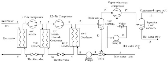
Figure 1.
Schematic of CHPVC.
2.2. Heat Pump and Two-Stage Water Vapor Compression System
Figure 2 shows the schematic of the heat pump and two-stage water vapor compression system (HPTVC) and its nominal working condition. This system includes a heat pump and a two-stage water vapor compression cycle. R134a is the refrigerant of the heat pump. The first stage of the vapor compressor is the centrifugal compressor, and the second stage of the vapor compressor is the twin-screw compressor with water injection. The waste heat source temperature is 45 °C, and the required vapor is 150 °C and 0.47 MPa. Similarly, for the vapor centrifugal compressor, the pressure ratio should not be too large, and the suction pressure should not be much lower than the atmospheric pressure. Furthermore, to compare HPTVC with CHPVC, the nominal condensation temperature of the R134a in the cascade condenser is set at 80 °C. The nominal suction pressure of the vapor centrifugal compressor is set as 0.031 MPa, and the nominal suction pressure of the vapor twin-screw compressor is set as 0.07 MPa.
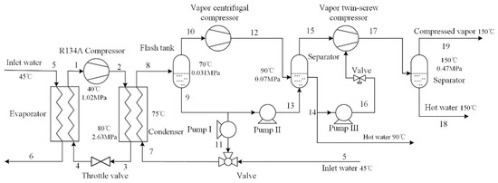
Figure 2.
Schematic of HPTVC.
3. Mathematical Model
3.1. Modeling of Cycle
Based on the first thermodynamic laws, a mathematical model is established to evaluate the performance of two systems from the perspective of energy efficiency. In order to simplify the theoretical calculation, the following assumptions are made as follows [13,14,24,25,26,27]:
- (1)
- All components operate under steady conditions.
- (2)
- The temperature loss and pressure loss of the working fluids are ignored.
- (3)
- The superheating degree is set to 5 °C, and the sub-cooling degree is set to 3 °C.
- (4)
- The heat transfer efficiency of the heat exchanger is assumed to be 100%.
- (5)
- The minimum heat transfer temperature difference in all heat exchangers is assumed to be 5 °C.
- (6)
- The efficiency of the pump is assumed to be 80%.
- (7)
- The vapor at the outlet of the compressor is saturated.
For the R134a heat pump cycle, the power consumption and the heating capacity can be calculated as follows:
For the R245fa heat pump cycle, the power consumption and the heating capacity can be calculated as follows:
For the single-stage water vapor compression, the injected water pressure is equal to the discharge pressure of the vapor compressor, which means that the injected water is used to reduce the discharge temperature of the vapor compressor and does not consume the compression work. Hence, the power consumption and the energy increment () of the working fluid can be calculated as follows:
where is the water-injection ratio, which can refer to Shen’s work [18]. The calculation process of the pump can refer to Liu’s work [28].
For the two-stage water vapor compression, the power consumption and the energy increment ( of the working fluid can be calculated as follows:
where n, k, and Z are the polytropic index, isentropic index, and compressibility factor, respectively. The calculation process of the centrifugal vapor compressor can refer to Shen’s work [18].
3.2. Modeling of Heat Pump Compressor
In this work, a twin-screw compressor is applied in the heat pump. To improve the calculation accuracy, the efficiency of the compressor applied in the heat pump is calculated under different working conditions. A thermodynamic model based on the first law of thermodynamics and mass conservation is established to obtain the isentropic efficiency. The following assumptions are made to simplify the calculation process [29,30]:
- (1)
- The working fluid flow process is assumed to be isentropic.
- (2)
- The pressure and temperature of the working fluid are homogeneous within the control volume.
- (3)
- The pressure loss in the discharge process is neglected.
- (4)
- Oil is assumed to be an incompressible fluid.
On the basis of the geometric characteristics, the control volume of the twin-screw compressor in the compression process can be simplified as shown in Figure 3, which includes the inlet and outlet ports of the refrigerant, the leakage paths, and the oil-injected port.
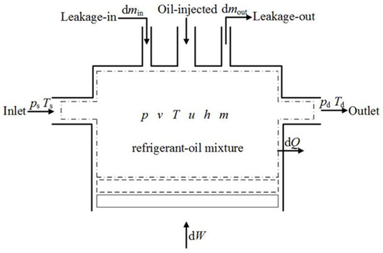
Figure 3.
Schematic of the control volume of the twin screw compressor in the compression process.
Based on the first law of thermodynamics and mass conservation, the internal energy and the mass of the refrigerant versus the rotation angle of the male rotor φ in the control volume can be expressed as follows [29,30]:
where Q and W represent the heat transfer and the work, respectively, which can be calculated as follows:
where αw is the heat transfer coefficient between the refrigerant and the surface of the working chamber. Aw represents the area of the working chamber surface.
While calculating the mass variation in the control volume, the leakage paths should be identified. In the twin-screw compressor, five leakage paths have been identified by Wu et al. [29]. The mass flow rate leaking into and out of the control volume can be calculated as follows:
where C, A, and N are the flow coefficient, area of leakage clearance, and operation speed.
Based on the calculation above, the pressure and temperature versus the rotation angle of the male rotor in the control volume can be calculated as follows:
In this work, the main parameters of the twin-screw compressor and the five leakage paths refer to a refrigeration compressor using R134a as the working fluid [30]. The built-in volume ratio is 2.4, which matches the working conditions shown in Figure 1 and Figure 2. The isentropic efficiency of a twin-screw compressor applied in a heat pump can be calculated as follows:
where Pis is the power consumption of the ideal isentropic process, and Pin represents the indicated power.
Moreover, in the actual application, the power consumption of the motor should be considered [30]. In this work, the efficiencies of the motor are assumed as 95% according to common practice. Hence, the compression efficiency of a twin-screw compressor applied in a heat pump can be calculated as follows:
3.3. Efficiency of Vapor Compressor
In this work, a twin-screw compressor is applied in the single-stage vapor compression cycle to complete the compression process with a pressure ratio of more than 3. For the two-stage vapor compression cycle, the saturation temperature rise is up to 80 °C with a high pressure lift. To obtain high operation efficiency, the centrifugal compressor is applied in the first stage with a pressure ratio below 3, and the twin-screw compressor is applied in the second stage to complete the compression with a high pressure ratio [18]. The compression efficiency of the vapor twin-screw compressor and the polytropic efficiency of the vapor centrifugal compressor can be obtained based on the pressure ratio and is shown in Table 1 [18,20,31,32].

Table 1.
Efficiency of vapor compressor.
3.4. Evaluation Index
The coefficient of performance (COP) is the most significant index to evaluate thermal performance. Generally, COP is the ratio of heating capacity to power consumption for heat pump systems. However, in these two systems with water vapor compression, water vapor is used as a heat source for heating purposes, and the heating capacity of water vapor cannot be calculated directly. Hence, in this work, COP is the ratio of the energy increment of water vapor to the total power consumption and can be calculated as follows:
For CHPVC, the COP can be calculated as follows:
For HPTVC, the COP can be calculated as follows:
3.5. Model Verification
To evaluate the accuracy of the simulation results, the basic performance parameters of the R134a compressor, R245fa compressor, R134a heat pump cycle, and R245fa heat pump cycle, including isentropic efficiency and COP, are compared with the presented results in the literature under the same working conditions. Considering the similarity of the pressure ratio, Zhang’s work and Xu’s work are used for comparison [25,30]. However, in Zhang’s work, the COP is obtained under refrigeration conditions. Hence, in this paper, the COP in Zhang’s work for refrigeration needs to be converted into the COP for heating. Table 2 shows the comparison results, and the errors are within 3.5%. As the power consumption of the motor is considered, the simulated COP in this paper is lower than the COP presented in Xu’s work, which is reasonable.
Table 2.
Comparison of isentropic efficiency and COP.
4. Results and Discussion
4.1. Mass Flow Rate of Each Working Fluid
Table 3 shows the mass flow rate of each working fluid under the operating conditions shown in Figure 1 and Figure 2, while the mass flow rate of the inlet water of the heat source is set as 100 kg∙s−1. Obviously, while the mass flow rate of the inlet water is the same, CHPVC can provide more required water vapor, which is 16.8% higher than that of HPTVC. Moreover, the mass flow rate of R134a in HPTVC is 19.24 kg∙s−1, which is 8.21% more than that in CHPVC.
Table 3.
Mass flow rate of each working fluid.
4.2. Influence of R134a Evaporation Temperature
Figure 4 shows the COP variation versus the R134a evaporation temperature, which is from 35 °C to 45 °C, and the other operating parameters are shown in Figure 1 and Figure 2. Meanwhile, the inlet water temperature is 40 °C to 50 °C. With the increment of the R134a evaporation temperature, the temperature difference between the R134a evaporation temperature and the required vapor temperature decreases, which leads to the increment of the COP. Moreover, CHPVC has a higher COP, and with the increment of the R134a evaporation temperature, the COP difference between the two systems decreases. The maximum COP difference is 5.13% at the R134a evaporation temperature of 35 °C, and the minimum COP difference is 0.82% at the R134a evaporation temperature of 45 °C. The comparison results mean that while the temperature of the heat source is relatively low, CHPVC is a better system to raise the water vapor temperature. In addition, for HPTVC, a significant rise in the COP occurs at the R134a evaporation temperature between 38 °C and 39 °C. The major reason is that while the compression process changes from under-compression to over-compression, the simulated isentropic efficiency is significantly improved, which is similar to the results shown in Zhang’s work.
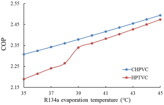
Figure 4.
COP versus the R134a evaporation temperature.
4.3. Influence of R134a Condensation Temperature
Figure 5 shows the variation of the COP versus the R134a condensation temperature. For the vapor centrifugal compressor, the suction pressure should not be too low, and the pressure ratio cannot be too large. Hence, during the calculation process, the R134a condensation temperature and the suction temperature of the vapor centrifugal compressor cannot be lower than 75 °C and 65 °C, respectively. The pressure ratio of the vapor centrifugal compressor cannot exceed 3. Other operation parameters can be referred to in Figure 1 and Figure 2.
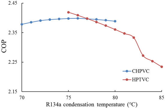
Figure 5.
COP versus the R134a condensation temperature.
For CHPVC, the COP increases first and then decreases with the increment of the R134a condensation temperature. The optimal COP is 2.398 at the R134a condensation temperature of 76 °C. However, for HPTVC, the COP decreases continuously with the increase in the R134a condensation temperature. The major reason is that the temperature lift driven by the vapor centrifugal compressor decreases. Moreover, a significant drop occurs at the R134a condensation temperature between 82 °C and 83 °C. The major reason is that the simulated isentropic efficiency decreases dramatically, while the compression process changes from under-compression to over-compression due to the increment of the pressure ratio of the R134a compressor. The optimal COP is 2.419 at the R134a condensation temperature of 75 °C. Meanwhile, the suction pressure and the pressure ratio of the vapor centrifugal compressor are 0.025 MPa and 2.8, respectively. Additionally, while the R134a condensation temperature exceeds 78 °C, CHPVC has a higher COP, and the reverse is true for the R134a condensation temperature below 77 °C. It can be deduced from the simulation results that for CHPVC, a suitable temperature lift of the cascade heat pump is important, and for HPTVC, a large temperature lift driven by the centrifugal vapor compressor is relatively good as its pressure ratio is allowed.
4.4. Influence of Suction Temperature of Vapor Twin-Screw Compressor
Figure 6 shows the variation of the COP versus the suction temperature of the vapor twin-screw compressor, and the other operating parameters are shown in Figure 1 and Figure 2. Similarly, the pressure ratio of the vapor centrifugal compressor cannot exceed 3. Hence, the suction temperature of the vapor twin-screw compressor is from 85 °C to 95 °C for HPTVC. For CHPVC, the COP grows first and then drops with the increment of the suction temperature. The optimal COP is 2.402 at the suction temperature of 92 °C, and the pressure ratio of the vapor compressor is 6.29. However, for HPTVC, with the increment of the suction temperature, the COP increases dramatically. The major reason is that the difference between the two compressors’ pressure ratios decreases with the increment of the suction temperature. The maximum COP is 2.434 at the suction temperature of 95 °C. Meanwhile, the pressure ratio of the vapor centrifugal compressor is 2.71, and the pressure ratio of the vapor twin-screw compressor is 5.63. Moreover, while the suction temperature exceeds 93 °C, HPTVC has a better COP, and the reverse is true for suction temperatures below 92 °C. It can also be deduced that for HPTVC, a large temperature lift driven by the vapor centrifugal compressor is relatively good as its pressure ratio is allowed.
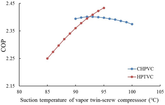
Figure 6.
COP versus the suction temperature of the vapor twin-screw compressor.
4.5. Influence of Required Vapor Temperature
Figure 7 shows the variation of the COP versus the required vapor temperature, which is from 145 °C to 155 °C, and the other operating parameters are shown in Figure 1 and Figure 2. An increment in the required vapor temperature results in a decrement in the COP. The major reason is that both the pressure ratio and the power consumption of the vapor twin-screw compressor increase with the increment of the required vapor temperature. The maximum COPs of CHPVC and HPTVC shown in Figure 7 are 2.466 and 2.474, respectively, at the required vapor temperature of 145 °C. Moreover, while the required vapor temperature exceeds 146 °C, the COP of CHPVC is higher than that of HPTVC, which means that CHPVC is more suitable for the required vapor with high temperature and HPTVC is more suitable for a relatively small temperature lift.
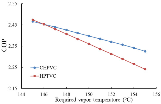
Figure 7.
COP versus the required vapor temperature.
4.6. The Optimal COP at the Nominal Working Condition
Figure 8 shows the COPs of the two systems versus the R134a condensation temperature and the suction temperature of the vapor twin-screw compressor at the inlet water temperature of 45 °C and the required vapor temperature of 150 °C. For CHPVC, it is obvious that both the R134a condensation temperature and the suction temperature of the vapor twin-screw compressor should not be too high, generally below 72 °C and 92 °C, respectively. This result means that the temperature lift provided by the cascade heat pump should not be too large, and the vapor twin-screw compressor should be used to provide a large saturation temperature rise. The optimal COP is 2.432 while the R134a condensation temperature is 71 °C, and the suction temperature of the vapor twin-screw compressor is 91 °C. For HPTVC, it is clear that the R134a condensation temperature should be relatively small, and the suction temperature of the vapor twin-screw compressor should be relatively large, which means that the pressure ratios of the R134a heat pump cycle should be relatively small, and the vapor centrifugal compressor should provide a large pressure rise as its pressure ratio allows. Moreover, the optimal COP of HPTVC is 2.436 while the R134a condensation temperature is 75 °C and the suction temperature of the vapor twin-screw compressor is 91 °C. Meanwhile, the pressure ratio of the vapor centrifugal compressor is 2.91.
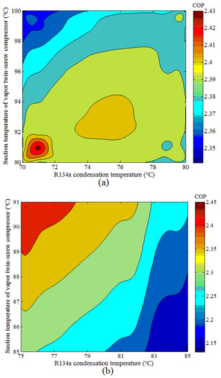
Figure 8.
COP versus the R134a condensation temperature and the suction temperature of the vapor twin-screw compressor (a) CHPTV; (b) HPTVC.
5. Conclusions
In this paper, two systems, CHPVC and HPTVC, have been proposed for waste heat recovery and water vapor supply with temperatures above 150 °C. The thermal performances of these two systems have been investigated and compared based on the proposed thermodynamic model. A compressor model is developed to accurately calculate the isentropic efficiency of R134a and R245fa compressors. The efficiency of the water vapor compressor has been calculated according to the pressure ratio, and the power consumption of the pump has also been considered. Four different parameters (inlet water temperature, R134a condensation temperature, suction temperature of twin-screw compressor, and required vapor temperature) have been used to analyze energy efficiency, and the optimal COPs at the nominal operation conditions have been calculated. According to the calculation results, the two systems show advantages at different working conditions, and the results of each analysis are given in detail below:
- While the mass flow rate of the inlet water is the same, CHPVC provides 16.8% more required water vapor than HPTVC at the nominal working conditions. Meanwhile, the mass flow rate of R134a in HPTVC is 8.21% more than that in CHPVC.
- While the inlet water temperature is 45 °C and the required vapor temperature is 150 °C, the optimal COPs of CHPVC and HPTVC are 2.432 and 2.436 respectively.
- CHPVC is more suitable for the required vapor with high temperatures. Moreover, the temperature lift provided by the cascade heat pump should not be too large, and the suction temperature of the vapor twin-screw compressor is generally around 90 °C.
- HPTVC is more suitable for a relatively small temperature difference between the inlet water and the required vapor. In addition, the temperature rise provided by the R134a heat pump cycle should be relatively small, and a large temperature lift provided by the vapor centrifugal compressor is increasingly efficient as its pressure ratio allows.
Author Contributions
Investigation, C.Z.; Data curation, D.C.; Writing—original draft, X.P.; Writing—review & editing, J.C.; Supervision, J.X. All authors have read and agreed to the published version of the manuscript.
Funding
This research received no external funding.
Conflicts of Interest
The authors declare no conflict of interest.
Nomenclature
| A | area (m2) |
| C | flow coefficient |
| ΔΕ | energy increment (W) |
| h | specific enthalpy (kJ·kg−1) |
| k | isentropic index |
| m | mass flow rate (kg∙s−1) |
| N | operation speed (r∙min−1) |
| n | polytropic index |
| P | power consumption (W) |
| p | pressure (Pa) |
| Q | heating capacity (W) |
| Rg | gas constant (J∙kg−1∙K−1) |
| T | temperature (K or °C) |
| u | specific internal energy (kJ·kg−1) |
| V | volume (m3) |
| v | specific volume (m3·kg−1) |
| W | power (W) |
| x | water-injection ratio |
| Z | compressibility factor |
| α | heat transfer coefficient (W∙m−2·K−1) |
| η | efficiency |
| ρ | density (kg∙m−3) |
| φ | rotation angle (°) |
| Subscripts | |
| c | compressor/compression |
| g | gas |
| H | heat |
| i | inlet |
| in | indicated |
| is/s | isentropic |
| m | mechanical |
| o | outlet |
| P | pump |
| pol | polytropic |
| T | temperature |
| t | total |
| v | volume |
| w | wall |
References
- Department of Energy Statistics of National Statistics Bureau of China. Yearbook of Energy Statistics of China; Chinese Statistics Press: Beijing, China, 2011; p. 109. (In Chinese) [Google Scholar]
- Zhang, J.; Zhang, H.; He, Y.; Tao, W. A comprehensive review on advances and applications of industrial heat pump based on the practices in China. Appl. Energy 2016, 178, 800–825. [Google Scholar] [CrossRef]
- Forman, C.; Muritala, I.K.; Pardemann, R.; Meyer, B. Estimating the global waste heat potential. Renew. Sustain. Energy Rev. 2016, 57, 1568–1579. [Google Scholar] [CrossRef]
- Harwardt, A.; Marquardt, W. Heat-integrated distillation columns: Vapor recompression or internal heat integration? AIChE J. 2012, 58, 3740–3750. [Google Scholar] [CrossRef]
- Bless, F.; Arpagaus, C.; Bertsch, S.S.; Schiffmann, J. Theoretical analysis of steam generation methods—Energy, CO2 emission, and cost analysis. Energy 2017, 129, 114–121. [Google Scholar] [CrossRef]
- Nandhini, R.; Sivaprakash, B.; Rajamohan, N. Waste heat recovery at low temperature from heat pumps, power cycles and integrated systems—Review on system performance and environmental perspectives. Sustain. Energy Technol. Assess. 2022, 52, 102214. [Google Scholar] [CrossRef]
- Yan, H.Z.; Hu, B.; Wang, R.Z. Air-source heat pump for distributed steam generation: A new and sustainable solution to replace coal-fired boilers in China. Adv. Sustain. Syst. 2020, 4, 2000118. [Google Scholar] [CrossRef]
- Lee, G.; Lee, B.; Wang, E.; Ra, H.S.; Cho, J.; Baik, Y.J.; Shin, H.K.; Lee, Y.S. A study on the development of development of high temperature heat pump for the generation of industrial process steam and construction of demonstration site. In Proceedings of the Korean Society of Equipment Engineering Conference, Busan, Korea, 10–12 October 2018. [Google Scholar]
- Jiang, J.T.; Hu, B.; Wang, R.Z.; Yu, Z.Q.; Mao, G.L. Multi-function thermal system with natural refrigerant for a wide temperature range. Appl. Therm. Eng. 2019, 162, 114189. [Google Scholar] [CrossRef]
- Bamigbetan, O.; Eikevik, T.M.; Neksa, P.; Bantle, M.; Schlemminger, C. Experimental investigation of a prototype R-600 compressor for high temperature heat pump. Energy 2019, 169, 730–738. [Google Scholar] [CrossRef]
- Watanabe, C. Trends in industrial heat pump technology in Japan. IEA Heat Pump Newsl. 2012, 30, 36–38. [Google Scholar]
- Jiang, J.; Hu, B.; Wang, R.Z.; Deng, N.; Cao, F.; Wang, C. A review and perspective on industry high-temperature heat pumps. Renew. Sustain. Energy Rev. 2022, 161, 112106. [Google Scholar] [CrossRef]
- Kosmadakis, G.; Arpagaus, C.; Neofytou, P.; Bertsh, S. Techno-economic analysis of high-temperature heat pumps with low-global warming potential refrigerants for upgrading waste heat up t0 150 °C. Energy Convers. Manag. 2020, 226, 113488. [Google Scholar] [CrossRef]
- Chamoun, M.; Rulliere, R.; Haberschill, P.; Berail, J.F. Dynamic model of an industrial heat pump using water as refrigerant. Int. J. Refrig. 2012, 35, 1080–1091. [Google Scholar] [CrossRef]
- Chamoun, M.; Rulliere, R.; Haberschill, P.; Peureux, J.L. Modelica-based modeling and simulation of a twin screw compressor for heat pump applications. Appl. Therm. Eng. 2013, 58, 479–489. [Google Scholar] [CrossRef]
- Chamoun, M.; Rulliere, R.; Haberschill, P.; Peureux, J.L. Experimental and numerical investigations of a new high temperature heat pump for industrial heat recovery using water as refrigerant. Int. J. Refrig. 2014, 44, 177–188. [Google Scholar] [CrossRef]
- Li, Q.; Piechna, J.; Müller, N. Design of a novel axial impeller as a part of counter-rotating axial compressor to compress water vapor as refrigerant. Appl. Energy 2011, 88, 3156–3168. [Google Scholar] [CrossRef]
- Shen, J.; Feng, G.; Xing, Z.; Wang, X. Theoretical study of two-stage water vapor compression systems. Appl. Therm. Eng. 2019, 147, 972–982. [Google Scholar] [CrossRef]
- Shen, J.; Xing, Z.; Wang, X.; He, Z. Analysis of a single-effect mechanical vapor compression desalination system using water injected twin screw compressors. Desalination 2014, 333, 146–153. [Google Scholar] [CrossRef]
- Shen, J.; Xing, Z.; Zhang, K.; He, Z.; Wang, X. Development of a water-injected twin-screw compressor for mechanical vapor compression desalination systems. Appl. Therm. Eng. 2016, 95, 125–135. [Google Scholar] [CrossRef]
- Diez, E.; Langston, P.; Ovejero, G.; Romero, M.D. Economic feasibility of heat pump in distillation to reduce energy use. Appl. Therm. Eng. 2009, 29, 1216–1223. [Google Scholar] [CrossRef]
- Li, Y.; Wu, H.; Liang, X.; Rong, C.; Chen, H. Experimental study of waste concentration by mechanical vapor compression technology. Desalination 2015, 361, 46–52. [Google Scholar] [CrossRef]
- Tian, Y.; Shen, J.; Wang, C.; Xing, Z.; Wang, X. Modeling and performance study of a water-injected twin-screw water vapor compressor. Int. J. Refrig. 2017, 83, 75–87. [Google Scholar] [CrossRef]
- Zhao, Z.; Tian, Y.; Hou, F.; Xing, Z. Performance analysis of a refrigerant extracting twin screw compressor employed in multi-temperature heat pump systems. Int. J. Refrig. 2016, 67, 383–394. [Google Scholar] [CrossRef]
- Xu, C.; Yang, H.; Yu, X.; Ma, H.; Chen, M.; Yang, M. Performance analysis for binary mixtures based on R245fa using in high temperature heat pumps. Energy Convers. Manag. X 2021, 12, 100123. [Google Scholar] [CrossRef]
- Liu, X.; Hu, Y.; Wang, Q.; Yao, L.; Li, M. Energetic, environmental and economic comparative analyses of modified transcritical CO2 heat pump system to replace R134a system for home heating. Energy 2021, 229, 120544. [Google Scholar] [CrossRef]
- Zhang, H.; Geng, X.; Shao, S.; Si, C.; Wang, Z. Performance analysis of a R134a/CO2 cascade heat pump in severe cold regions of China. Energy 2022, 239, 122651. [Google Scholar] [CrossRef]
- Liu, C.; Wang, Z.; Han, W.; Kang, Q.; Liu, M. Working domains of a hybrid absorption-compression heat pump for industrial applications. Energy Convers. Manag. 2019, 195, 226–235. [Google Scholar] [CrossRef]
- Wu, H.; Xing, Z.; Shu, P. Theoretical and experimental study on indicator diagram of twin screw refrigeration compressor. Int. J. Refrig. 2004, 27, 331–338. [Google Scholar]
- Zhang, Z.; Wang, Y.; Wu, X.; Pan, X.; Xing, Z. Theoretical and experimental research on the performance of twin screw compressor using R513A as R134a replacement. Proc. IMechE Part E J. Process. Mech. Eng. 2021, 235, 170–177. [Google Scholar] [CrossRef]
- Sarevski, M.N.; Sarevski, V.N. Thermal characteristics of high-temperature R718heat pumps with turbo compressor thermal vapor recompression. Appl. Therm. Eng. 2017, 117, 355–365. [Google Scholar] [CrossRef]
- Sarevski, M.N.; Sarevski, V.N. Characteristics of water vapor turbo compressors applied in refrigeration and heat pump systems. Int. J. Refrig. 2012, 35, 1484–1496. [Google Scholar] [CrossRef]
Publisher’s Note: MDPI stays neutral with regard to jurisdictional claims in published maps and institutional affiliations. |
© 2022 by the authors. Licensee MDPI, Basel, Switzerland. This article is an open access article distributed under the terms and conditions of the Creative Commons Attribution (CC BY) license (https://creativecommons.org/licenses/by/4.0/).