

Research on the Effects of Two-Sided Ground Surcharge/Unloading on Existing Shield Tunnels


Abstract
:1. Introduction
2. Indoor Model Test
2.1. Test Materials and Equipment
2.2. Test Conditions
2.3. Test Steps
- (1)
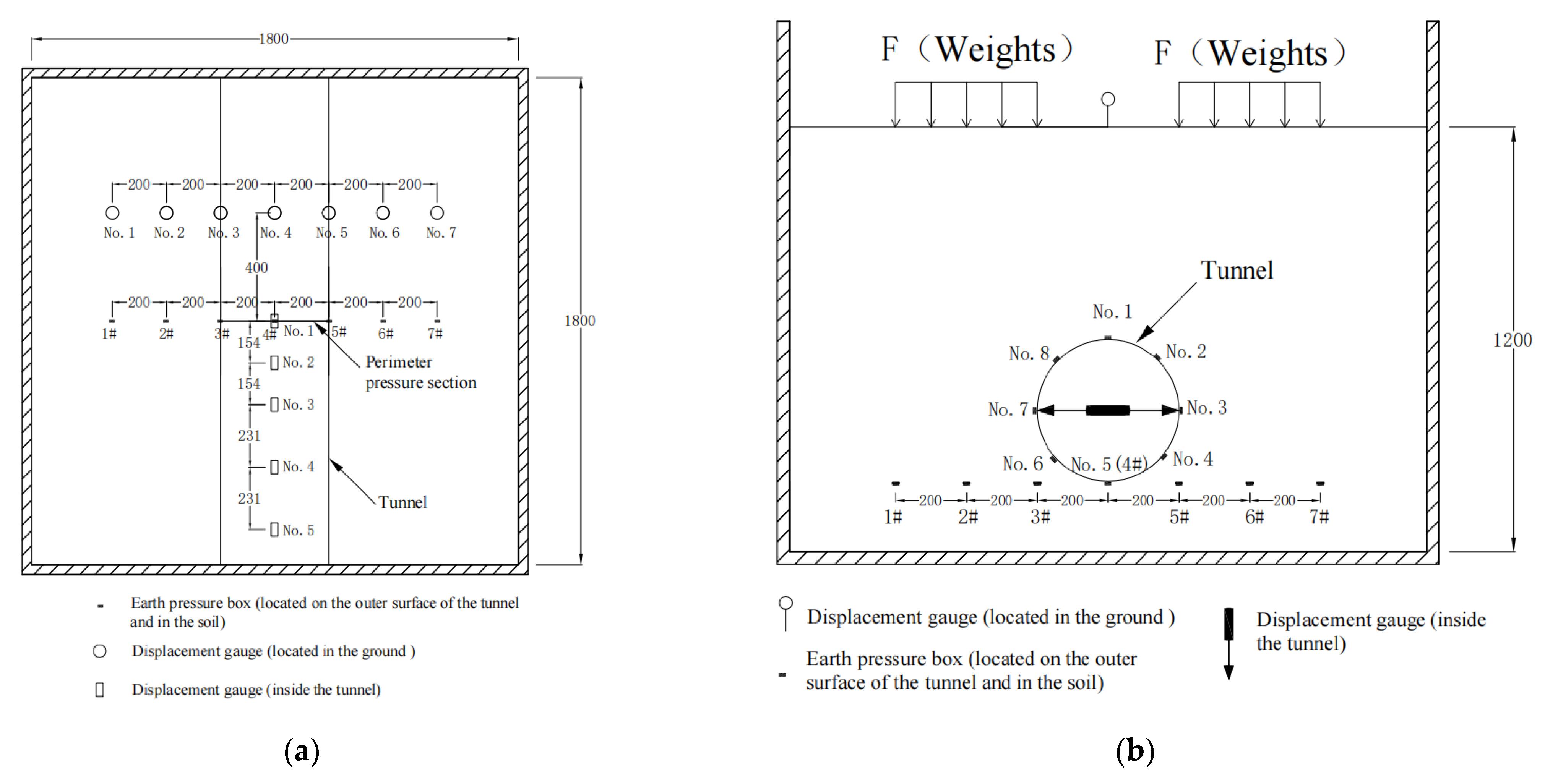
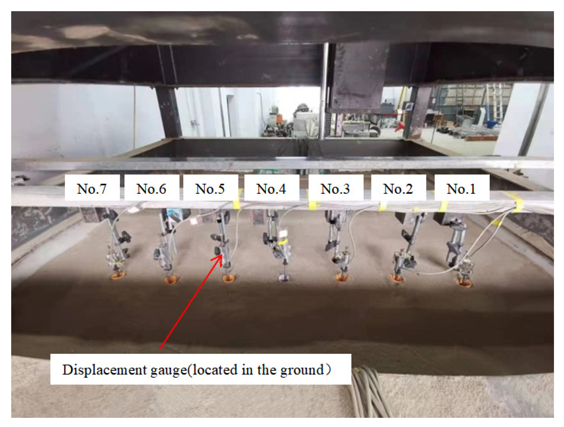
- First, the shift meter for measuring the lateral convergence value of the tunnel and the earth pressure box for measuring the tunnel pressure are installed at the designated position of the model tunnel, and then the model tunnel is lifted to the designated position of the model box, after which the sand is loaded into the model box for the test at 0.1 m/layer. If under Cases 1~3, this is performed until the total thickness of the soil layer reaches 1.2 m, and then the shift meter for measuring the ground settlement is installed on the surface of the sand. Then, the shift meter and the earth pressure box are connected to the resistive strain gauge and, finally, the sand is left to stand for more than 24 h. In the case of Case 4, the earth pressure box for measuring the earth pressure at the bottom of the central section of the tunnel is installed at 0.2 m, and the rest of the operation is the same as that of Cases 1~3. The layout of the shift meter for measuring the ground settlement on the sand surface is shown in Figure 4.
- (2)
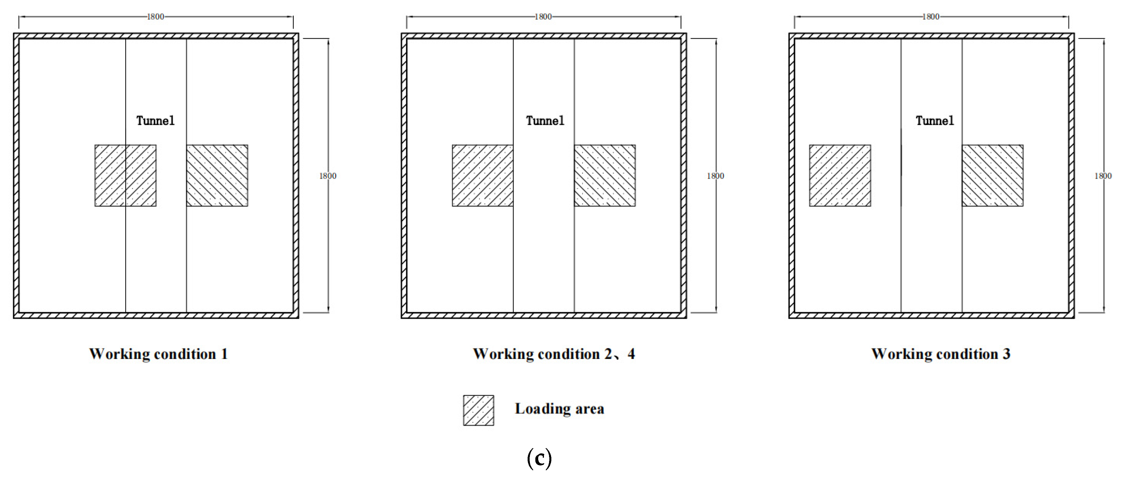
- Set all displacement gauges and earth pressure box readings to zero, put the 0.4 m × 0.4 m pressure plate in the designated position on the left side in Figure 3c according to the test condition, and surcharge 34.4 kg (including the weight of pressure plate), 68.8 kg, 103.2 kg, 137.6 kg, and 172.0 kg on the pressure plate with corresponding weights step by step. Then, put the 0.4 m × 0.4 m pressure plate in the designated position on the right side in Figure 3c, and surcharge 34.4 kg (including the weight of the pressure plate), 68.8 kg, 103.2 kg, 137.6 kg, and 172.0 kg with weights on the pressure plate step by step. Next, unload the weights on the left side of the pressure plate to 137.6 kg, 103.2 kg, 68.8 kg, 34.4 kg, and 0 kg. Finally, unload the weights on the right side of the pressure plate to 137.6 kg, 103.2 kg, 68.8 kg, 34.4 kg, and 0 kg. The duration of each level of surcharge and unloading is 0.5 h, and the shift meter and earth pressure box read the data every 1 s during the whole surcharge and unloading process.
3. Results and Discussion
3.1. The Impact of Dry Sand in Two-Sided Surcharge/Unloading on the Tunnel Below
3.1.1. The Effect on Lateral Convergence
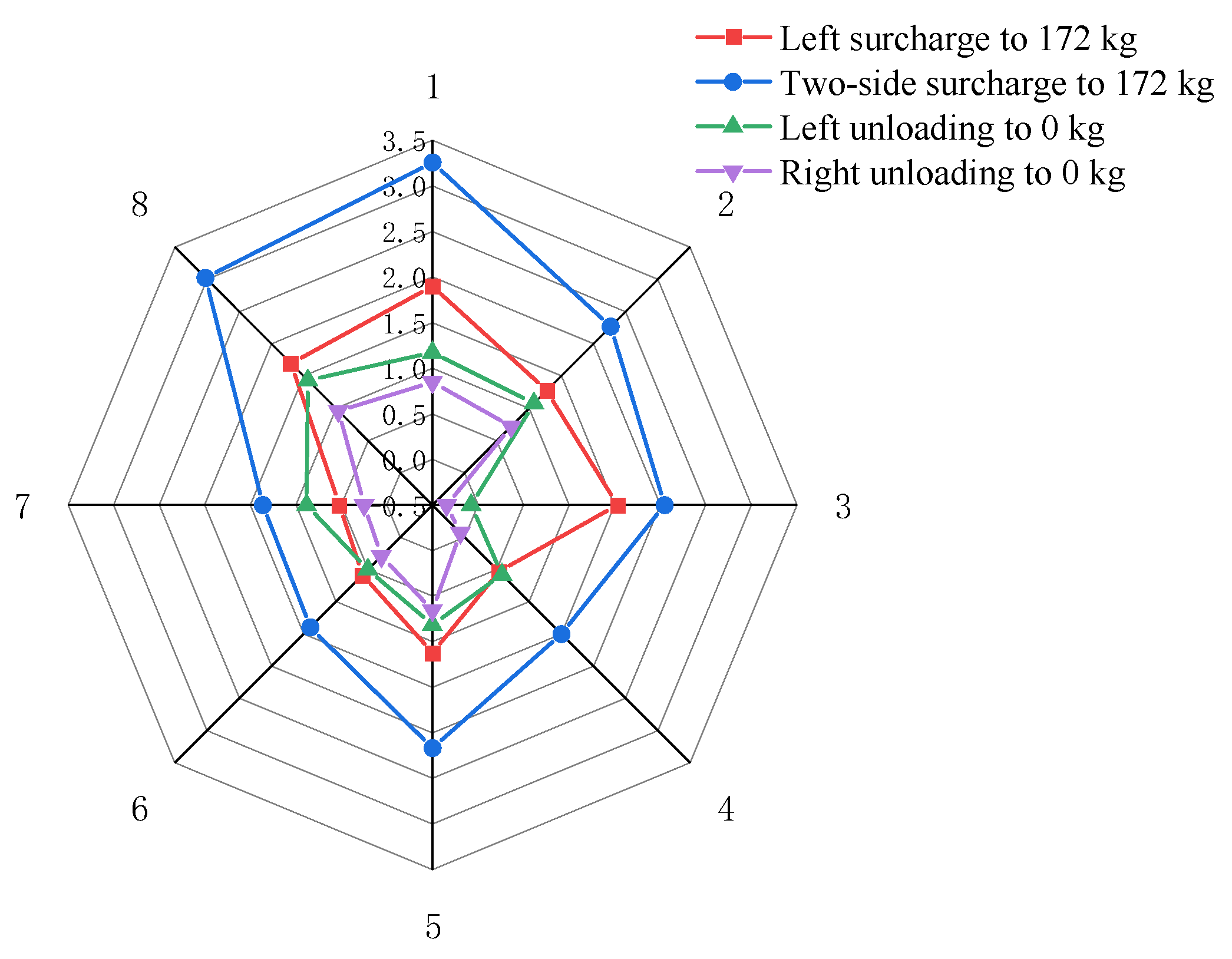
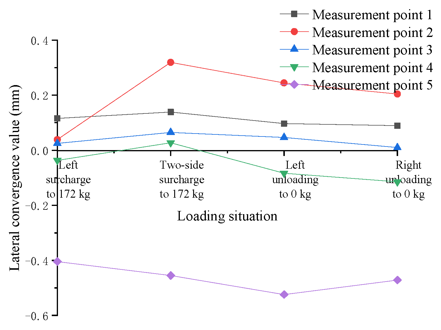
- (1)
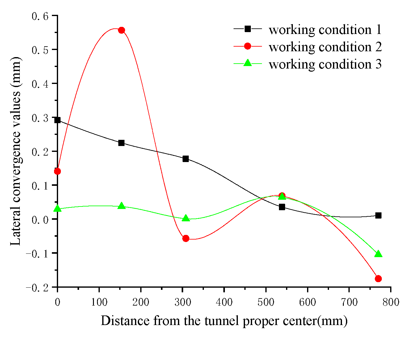
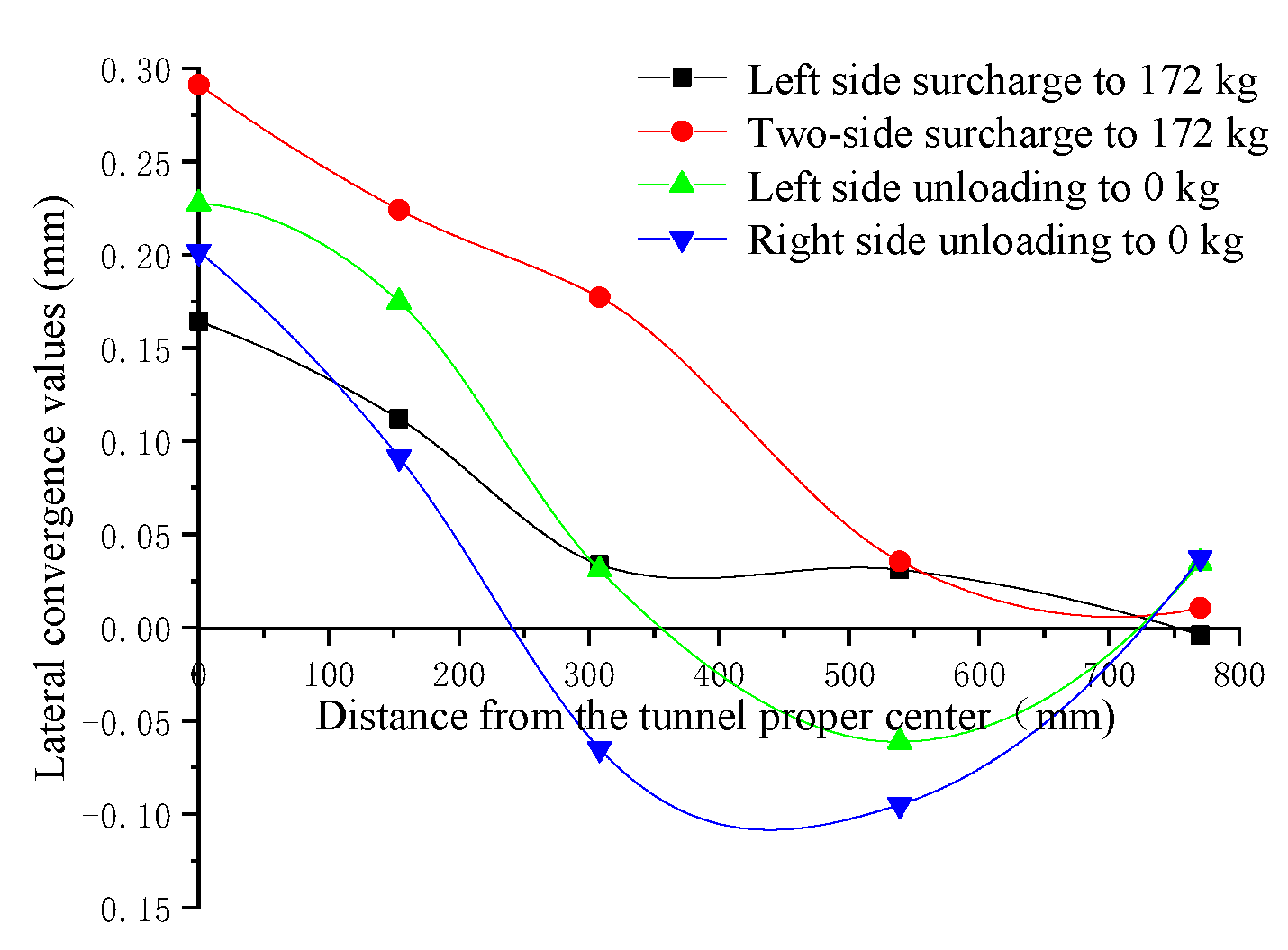
- In Cases 1~3, the tunnel’s maximum transverse convergence values occur when the eccentric surcharge is 172 kg on two sides of the tunnel, but the maximum transverse convergence value for Case 1 occurs at measurement point 1 (right in the middle of the tunnel), while Cases 2 and 3 occur at measurement point 2, due to the different locations of the loads on the two sides of the tunnel, resulting in different combined forces of the loads acting on the tunnel on two sides.
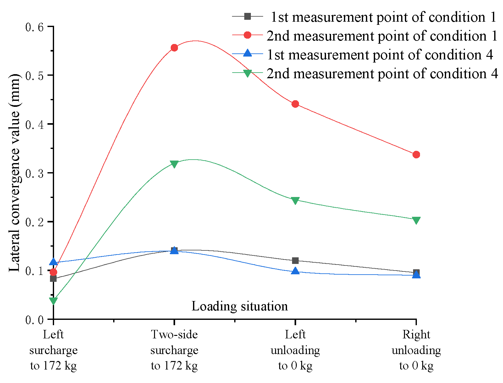
- (2)
- The maximum lateral convergence value of the tunnel in Case 1 is 0.2914 mm, the maximum lateral convergence value of the tunnel in Case 2 is 0.5562 mm, and the maximum lateral convergence value of the tunnel in Case 3 is 0.0368 mm, indicating that when the surcharge is applied on two sides of the tunnel, as the position of the left surcharge’s offset increases from 0.2 m to 0.6 m, the lateral convergence value first increases and then becomes smaller, and decreases rapidly after the surcharge offset reaches a certain degree.
- (3)
- Case 2 is a symmetric surcharge on two sides; after the eccentric surcharge on the left side is 172 kg, when the right side continues to surcharge to 172 kg, it is equivalent to the total load increasing by a factor of 1, but the local lateral convergence value of the tunnel increases by several times, which is extremely harmful to the tunnel.
- (1)
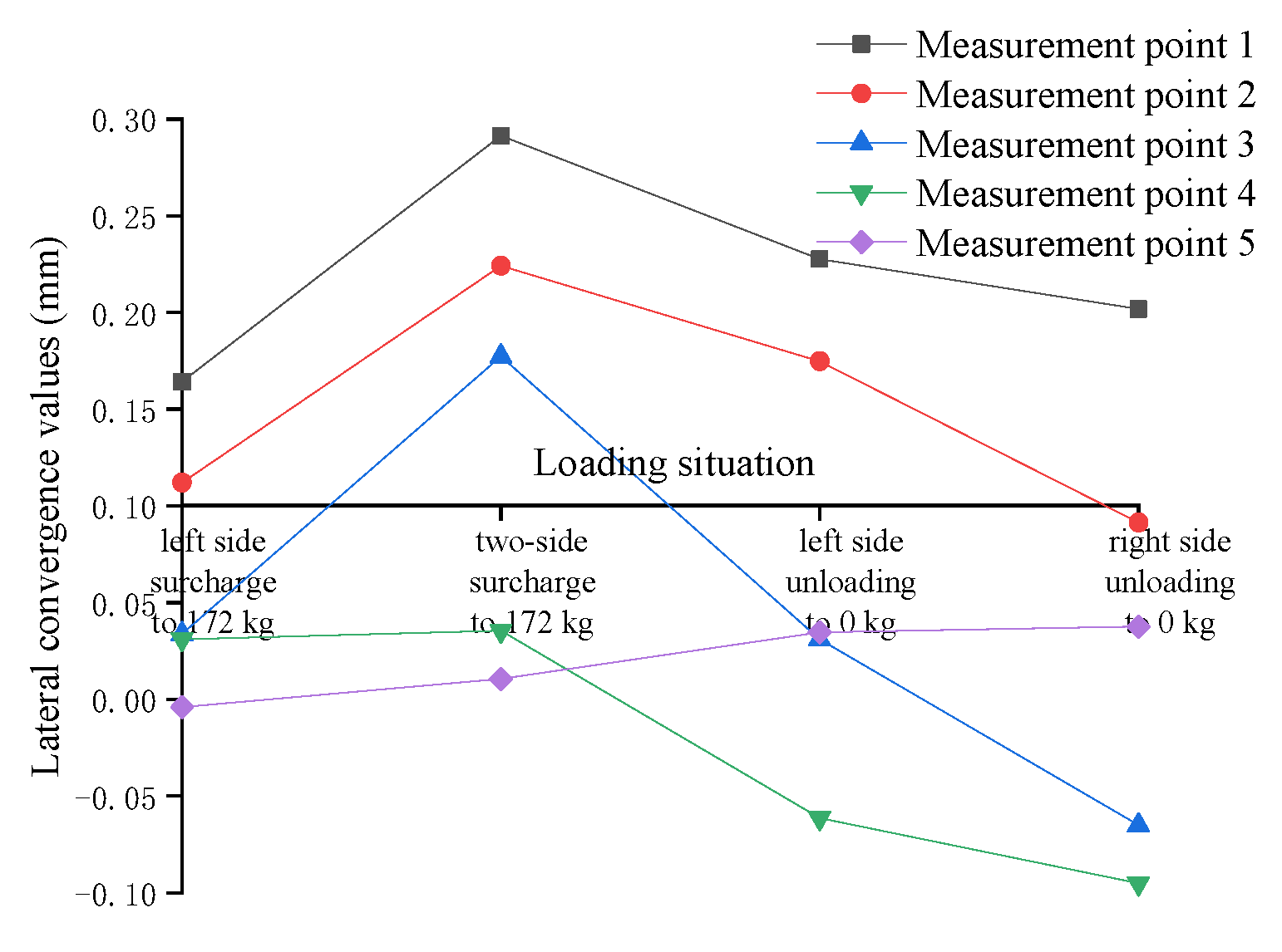
- When the surcharge is on two sides under dry sand soil, unloading on either side can effectively reduce the lateral convergence value of the tunnel. Taking measurement point 1 as an example, after unloading the surcharge on two sides, the lateral convergence value decreases from the maximum 0.2914 mm to 0.2017 mm, representing a reduction of 30.6%.
- (2)
- In the process of unloading a two-sided surcharge under dry sand soil, the lateral convergence value of the tunnel is negative, indicating that the tunnel section becomes laterally smaller at this time, which may be due to the redistribution of soil stresses during the unloading process, making the tunnel’s lateral convergence recover “excessively”.
- (3)
- The transverse convergence of measurement point 5 is less regular, because measurement point 5 is the farthest from the surcharge, and the transverse convergence value is small, while there is an obvious “boundary effect” near the edge of the model box.
3.1.2. Effect on Ground Settlement
- (1)
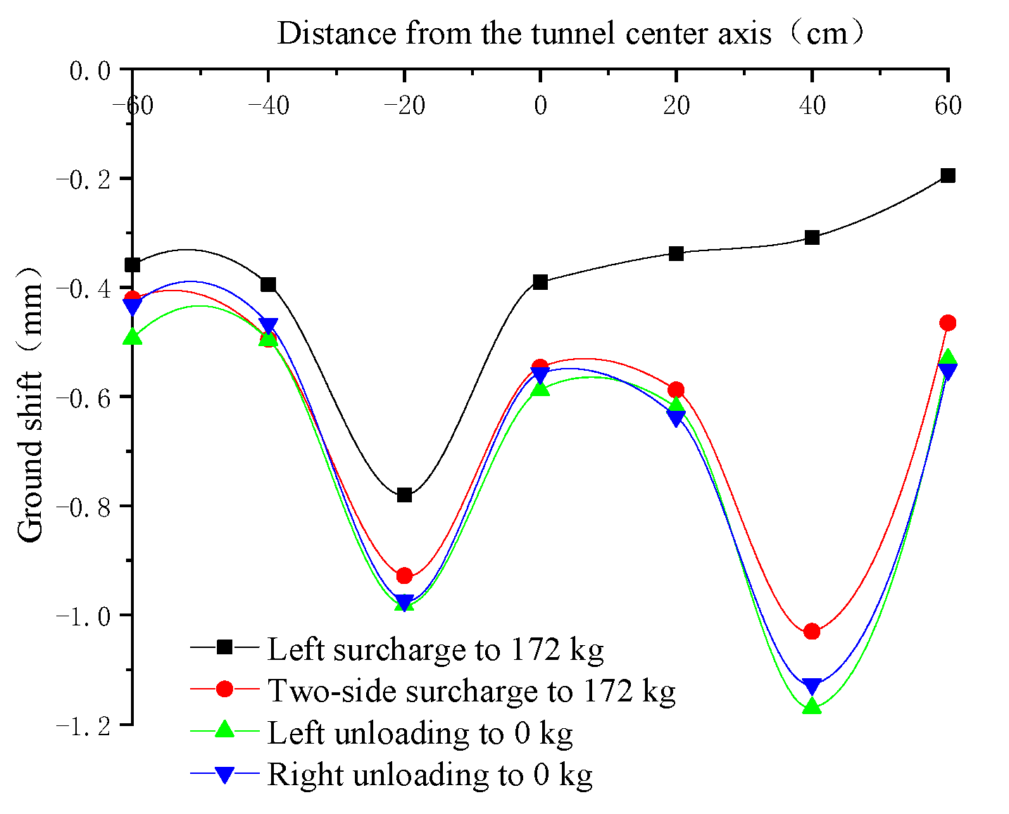
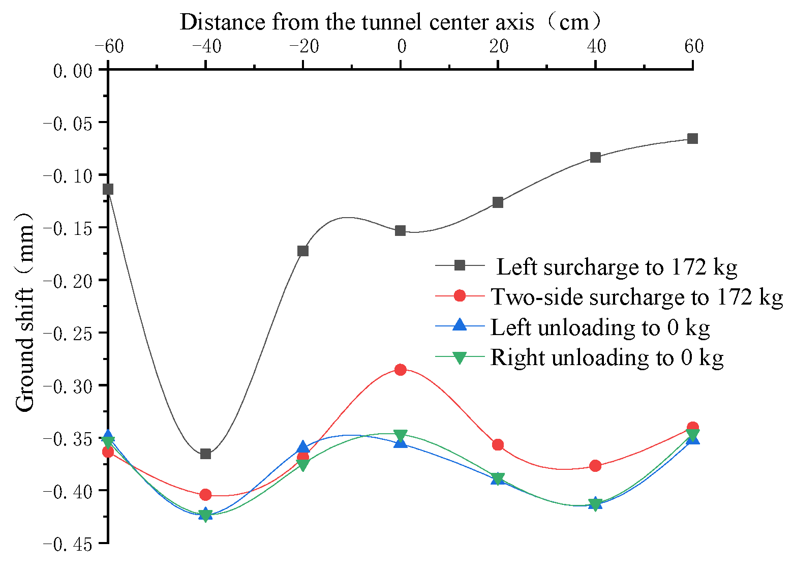
- As the position of the left surcharge’s offset increases from 0.2 m to 0.6 m, the peak of the left ground settlement also shifts, and the peak of the left settlement decreases from 0.9815 mm to 0.5925 mm in the process of the offset, which is mainly due to the change in the position of the left surcharge’s offset, resulting in the boundary effect becoming more and more obvious.
- (2)
- The amount of settlement at each measurement point of the ground first increases and then decreases during the unloading process, and the effect of unloading on the mitigation of ground settlement is not obvious, because the soil is still consolidating during the unloading process, causing the maximum amount of ground settlement. This is because during the unloading process, the soil is still consolidating, which leads to the maximum amount of ground settlement lagging behind.
- (3)
- The peak of the ground settlement on the left and right sides always occurs when the right surcharge is 172 kg and the left surcharge is finished unloading; the final peak of the ground settlement on the right side during the whole surcharge/unloading process is always larger than the final peak of the ground settlement on the left side. This may be related to the sequence of surcharge/unloading.
3.1.3. Influence on Additional Surrounding Pressure
- (1)
- As the position of the left surcharge offset increases from 0.2 m to 0.6 m, the additional surrounding pressure of the tunnel decreases sharply. Taking point 1 as an example, with a left surcharge of 172 kg, the additional surrounding pressure decreases from 1.9003 kPa to 0.2410 kPa when the left surcharge’s offset position increases from 0.2 m to 0.6 m, which is 87.3%; with the left and right surcharge of 172 kg, the additional surrounding pressure decreases from 3.2576 kPa to 0.3545 kPa when the left surcharge’s offset position increases from 0.2 m to 0.6 m, representing a decrease of 89.1%.
- (2)
- After surcharge on one side of the tunnel, if the other side continues to surcharge, it will cause the surrounding pressure to continue to increase, and when the surcharge on two sides reaches 172 kg, the local additional surrounding pressure of the tunnel increases by more than 100%, which is extremely harmful to the tunnel.
- (3)
- In dry sand, unloading can effectively reduce the additional surrounding pressure of the tunnel, but it will not eliminate the additional surrounding pressure immediately; after unloading is completed, the additional surrounding pressure will still exist in most of the tunnel to some extent. The more distant the surcharge location, the higher the residual proportion of additional pressure.
3.2. Influence of Two-Sided Surcharge/Unloading on the Tunnel Below Using Wet Sand
3.2.1. Influence on Lateral Convergence
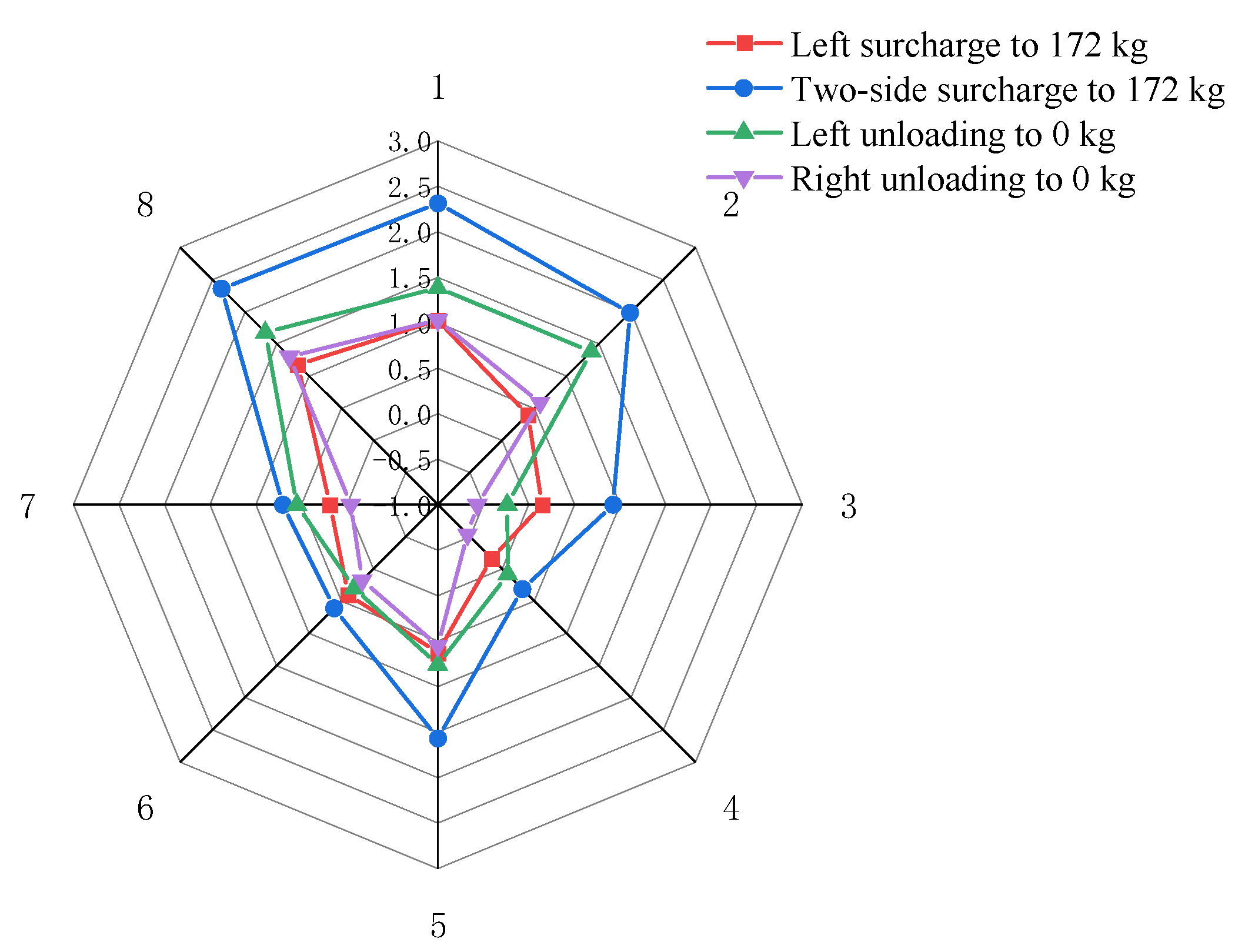
- (1)
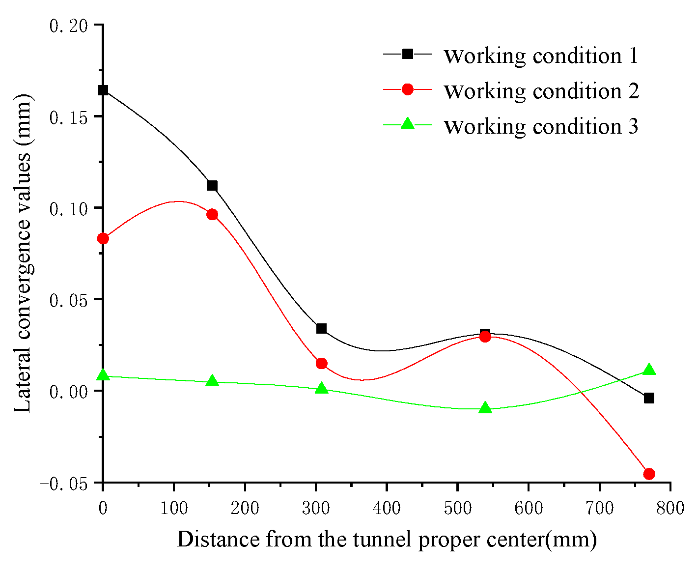
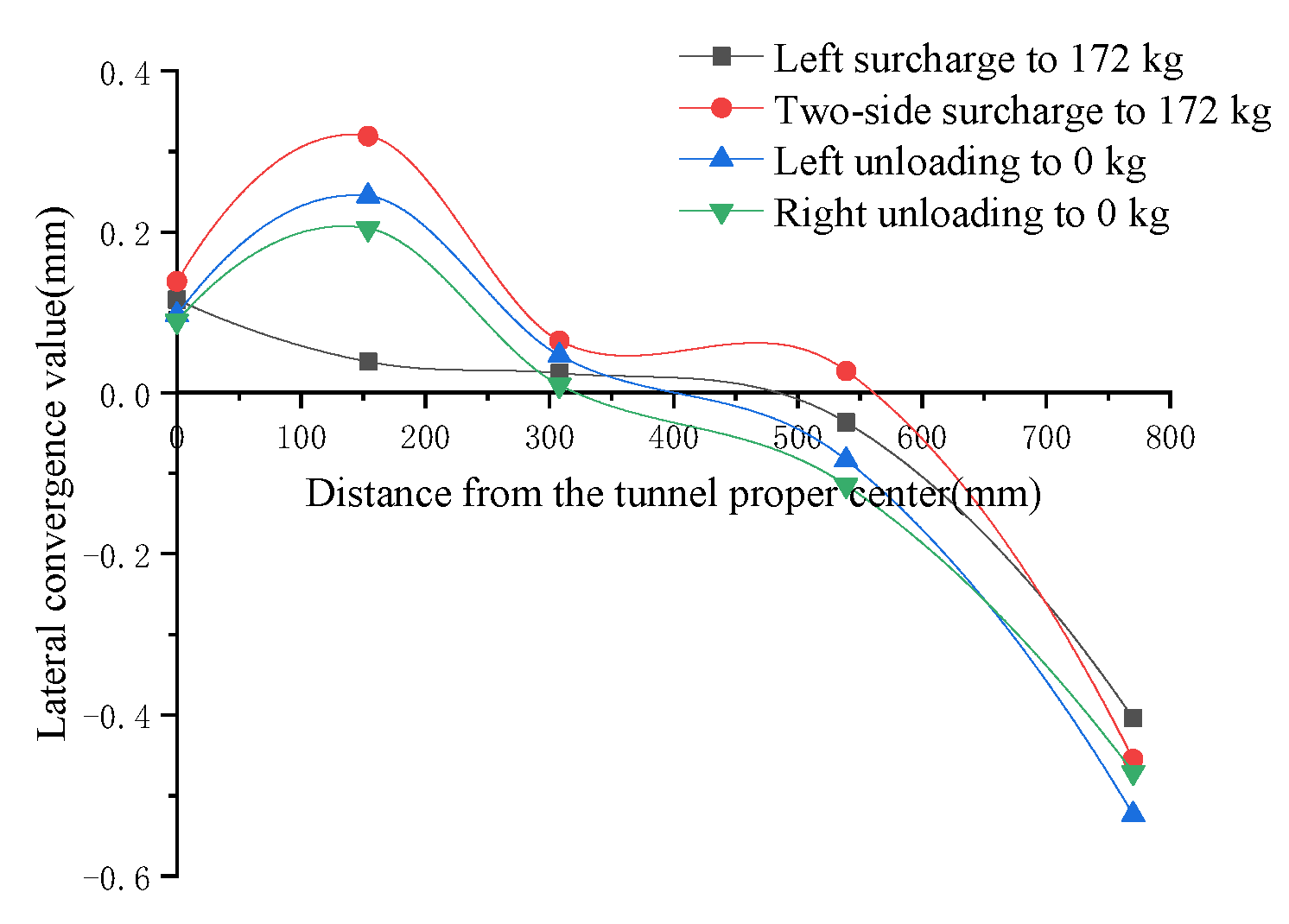
- In the wet sand, the maximum transverse convergence value of the tunnel occurs at measurement point 2 when the eccentric surcharge on two sides of the tunnel is 172 kg, which is consistent with the case of dry sand in soil under the same conditions, but the maximum transverse convergence value of the tunnel in the wet sand is 0.3193 mm—only 57.4% of the transverse convergence of the tunnel in the dry sand under the same conditions—indicating that under the same test conditions, compared with the dry sand, the maximum transverse convergence of the tunnel in the wet sand is significantly reduced.
- (2)
- The unloading of either side in wet sand can effectively reduce the lateral convergence value of the tunnel when two sides are surcharged, which is consistent with the performance under dry sand soil. Taking measurement point 2 as an example, after unloading the two-sided surcharge, the transverse convergence value is reduced from the maximum 0.3193 mm to 0.2044 mm, representing a reduction of 36.0%.
- (3)
- The lateral convergence value of measurement point 5 is obviously different from that of the other measurement points, which is influenced by the boundary effect of the model test.
3.2.2. Effect on Ground Settlement
- (1)
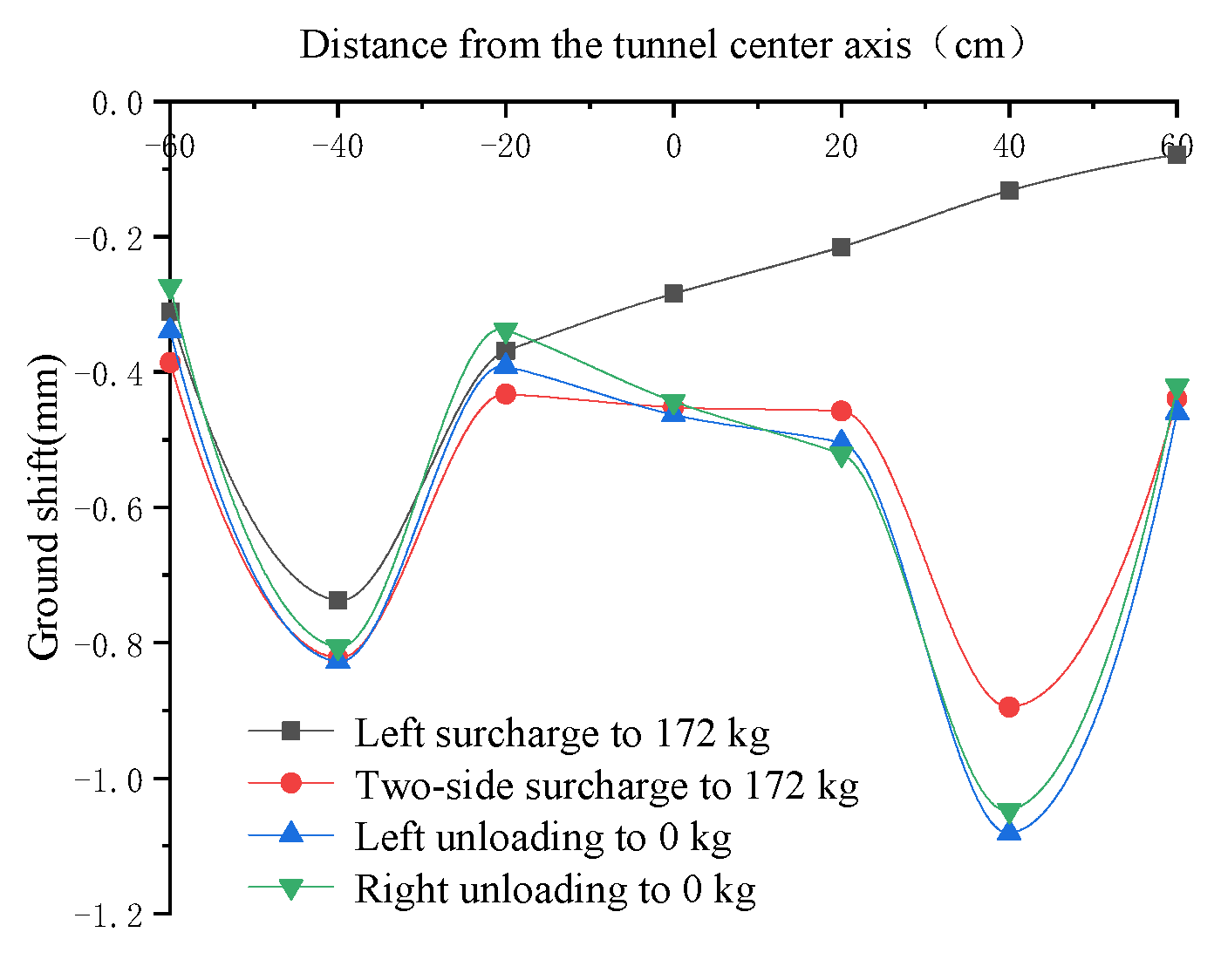
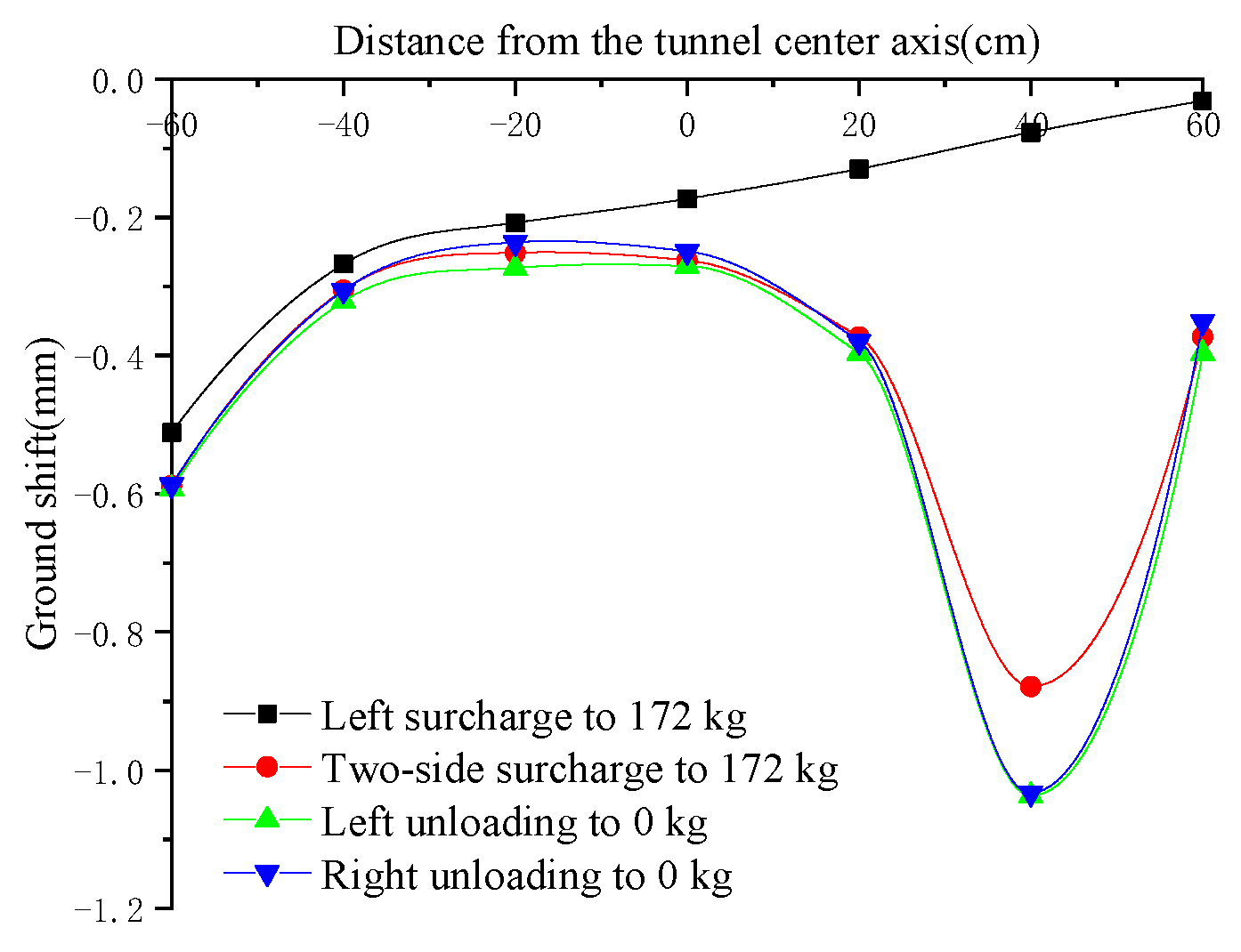
- When the soil is wet sand, the peak of ground settlement on the left and right sides occurs when the surcharge on the right side is 172 kg and the unloading on the left side is completed, while the effect of unloading on the mitigation of ground settlement is not obvious and is the same as when the soil is dry sand.
- (2)
- Under two-sided surcharge in wet sand, the peak of ground settlement on the two sides is not significant; the ground settlement caused by surcharge in wet sand is significantly smaller than that caused by surcharge in dry sand under the same conditions, and the peak ground settlement on the left and right sides in wet sand is 0.4232 mm. The peak settlement in wet sand is 0.4232 mm and 0.4133 mm, which is only 51.1% and 38.2% of the peak settlement on the left and right sides with dry sand soil, respectively.
3.2.3. Effect on Additional Surrounding Pressure
- (1)
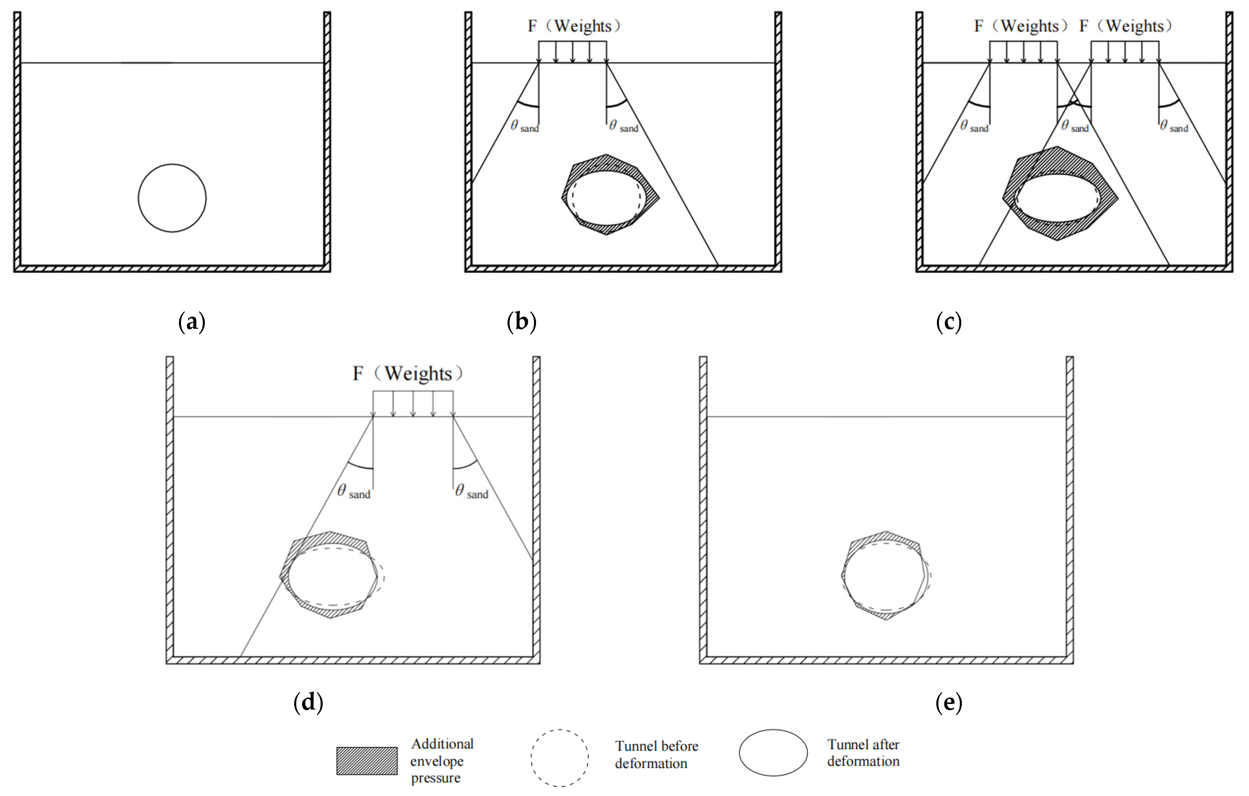
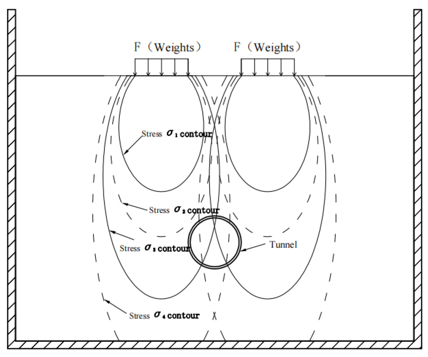
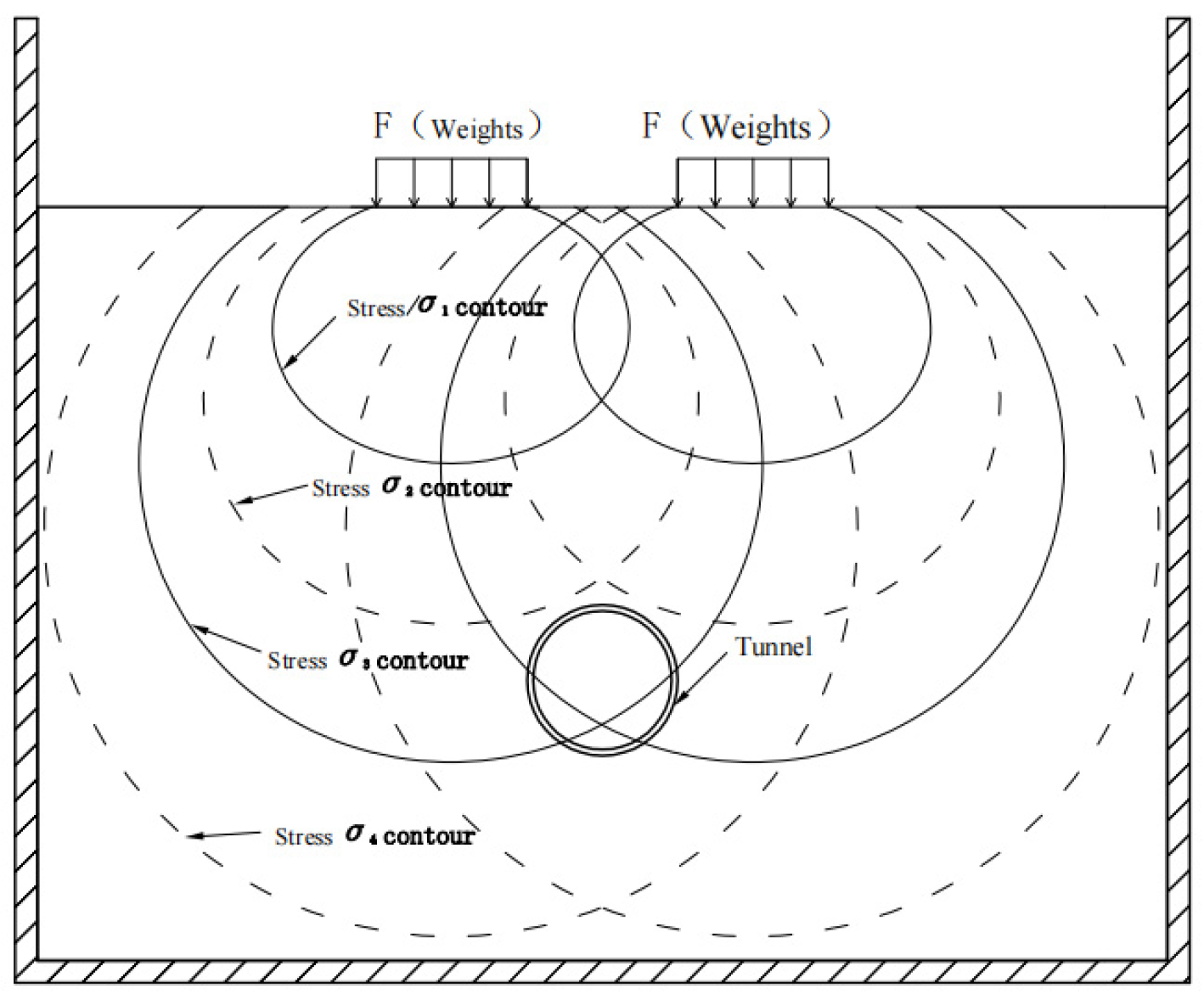
- The overall additional envelope pressure in the tunnel in wet sand is significantly larger than that in the tunnel in dry sand under the same conditions when the left surcharge is offset by 0.4 m, which is exactly the opposite of the overall additional envelope pressure in the tunnel in wet sand which, according to the literature, is significantly smaller than that in the tunnel in dry sand under the same conditions when the tunnel is surcharged directly above [8]. This is because the stress σ contours are flatter when the soil is wet sand, and the stress decreases slowly with the increase in the bias distance D. When the soil is dry sand, the stress σ contours are relatively long and thin, and the stress σ decreases rapidly with the increase in the deflection distance D. The stress σ contours for dry and wet sand under two-sided surcharge for Case 2 and Case 4 are shown schematically in Figure 22 and Figure 23, respectively.
- (2)
- In the wet sand, unloading can reduce the additional surrounding pressure of the tunnel to some extent, but the effect is obviously worse than that of dry sand unloading under the same conditions. Taking measurement point 1 as an example, in Case 2, the additional surrounding pressure is 2.3129 kPa when the two-sided surcharge is 172 kg, and the additional surrounding pressure is 1.0271 kPa after the two-sided surcharge is unloaded to 0 kg, with a reduction rate of 55.6%. In Case 4, the additional surrounding pressure is 2.4497 when two-sided surcharge is 172 kg, and the additional surrounding pressure is 1.0271 kPa after the two-sided surcharge is unloaded to 0 kg. kPa, while it is 2.3215 kPa after unloading to 0 kg on both sides, which is only a 5.2% decrease. This is because there is a lag in the reduction in the additional surrounding pressure of the tunnel after unloading in the wet sand condition due to the difference in soil, and a lag in the reduction in the additional surrounding pressure of the tunnel after unloading above the tunnel in the soft clay condition was also found in the literature [6].
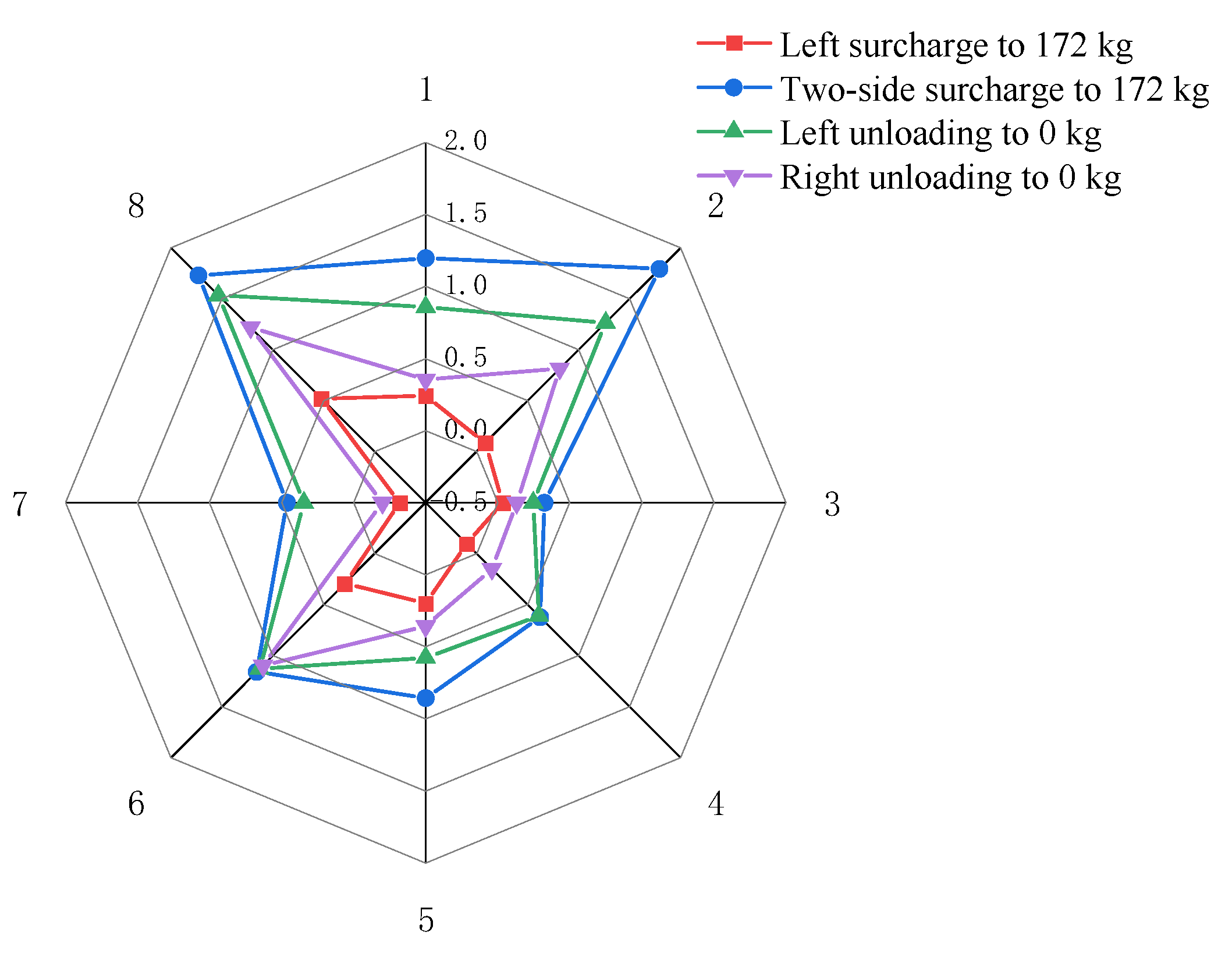
3.2.4. Influence on Additional Soil Pressure at the Bottom of the Tunnel
- (1)
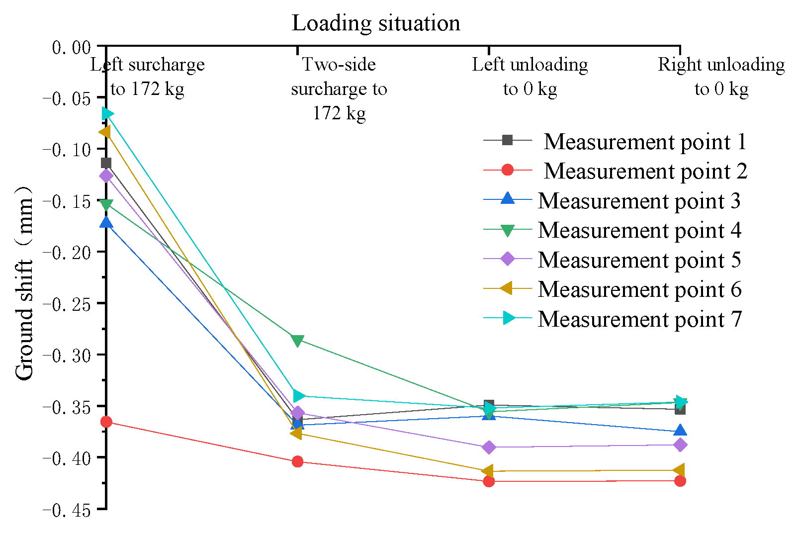
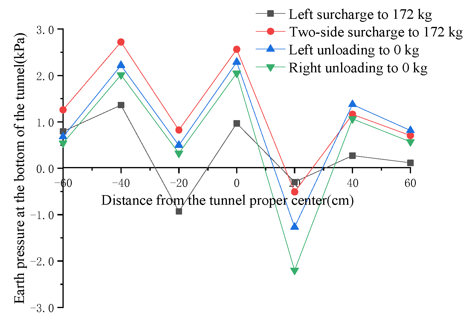
- Unloading can reduce the additional soil pressure of the tunnel subsoil to a certain extent, from the process of surcharge to 172 kg on two sides to the completion of unloading on both sides; the maximum reduction in the additional soil pressure of the tunnel subsoil is 0.7094 kPa, which occurs at measurement point 2 at −40 cm from the tunnel center; the maximum reduction in additional soil pressure of the tunnel subsoil is 61.0%, which occurs at measurement point 3 at −20 cm from the tunnel center. The maximum reduction in soil pressure is 61.0%, which occurs at measurement point 3 at −20 cm from the center of the tunnel.
- (2)
- During the process from surcharge to 172 kg on two sides to complete unloading to 0 kg on the left side (i.e., surcharge is still 172 kg on the right side), the additional soil pressure at measurement point 6 at 40 cm from the tunnel center increases instead of decreasing, and the increase reaches 0.2134 kPa, which is an increase of 18.35%. The local unloading of the surcharge will lead to an increase in the accumulated additional soil pressure of the tunnel subsoil, and the unloading sequence will affect the distribution of the additional soil pressure of the tunnel subsoil.
- (3)
- When the two-sided surcharge is 172 kg, the surcharge on both sides is symmetrical along the longitudinal axis of the tunnel, but the accumulated additional soil pressure of the tunnel’s subgrade is not completely symmetrical, which indicates that the surcharge order will affect the distribution of the additional soil pressure of the tunnel subgrade.
- (4)
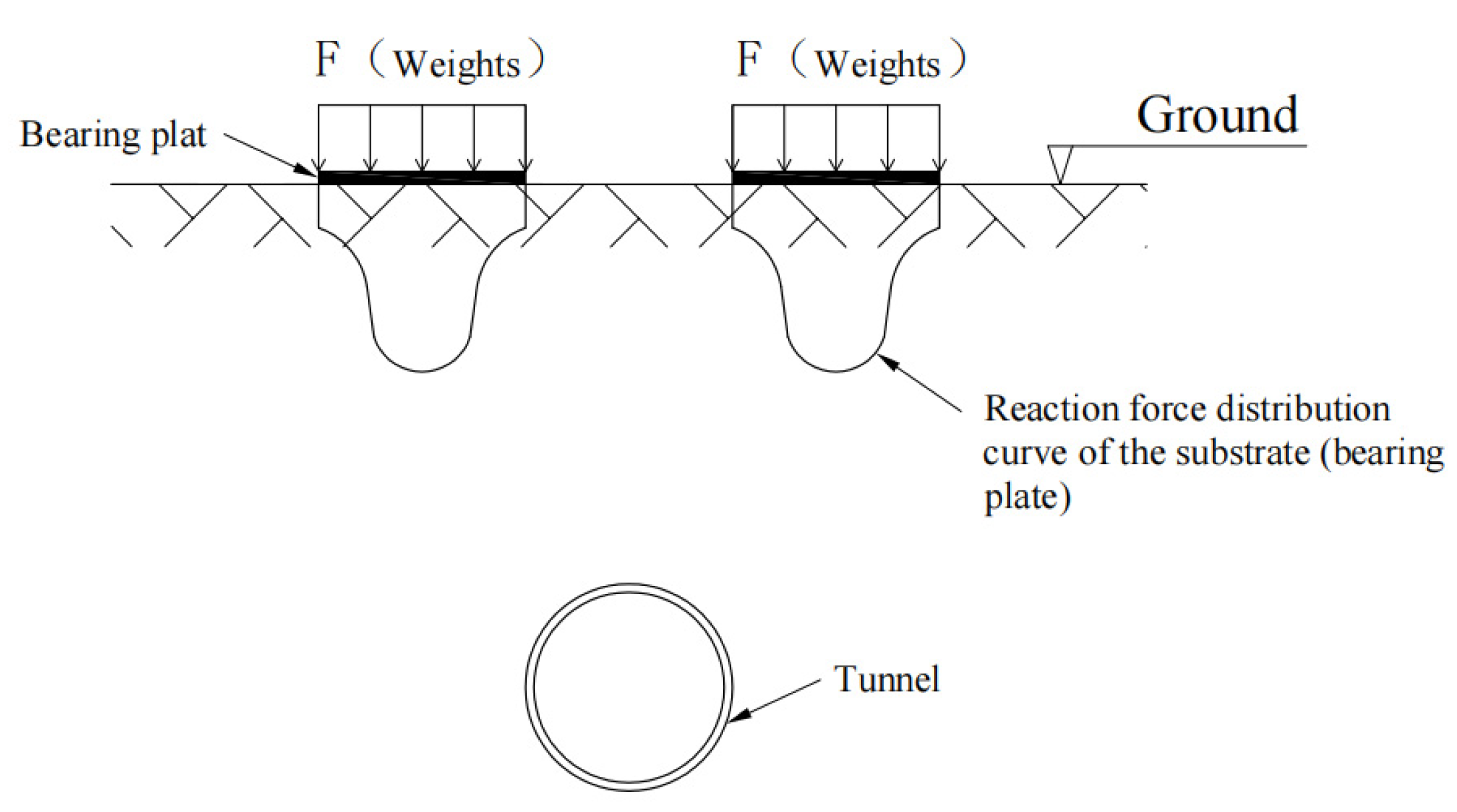
- When the two-sided surcharge is 172 kg, the additional soil pressure of the tunnel subgrade shows three peaks, one of which occurs at measurement point 4 at the bottom of the tunnel, probably because the stress concentration occurs here, resulting in a high additional soil pressure; two of these peaks occurred at measurement points 2 and 6 directly below the surcharge, and the range of the two-sided surcharge was 0.4 m × 0.4 m, but the difference between the accumulated additional soil pressure of the tunnel subsoil directly below the surcharge and the additional soil pressure of the tunnel subsoil below the edge of the surcharge was great, which was related to the characteristics of the sand soil itself—under the action of loading, the sand particles at the edge of the substrate (i.e., bearing plate) are very easy to extrude toward the lateral direction, so the middle of the substrate (i.e., bearing plate) must provide a greater balance of the reaction force, so that the reaction force distribution is inverted “convex”; specifically, refer to Figure 25.
4. Conclusions
- (1)
- The location of the maximum transverse convergence value of the existing shield tunnel is related to the location of the surcharge, because the location of the load on the two sides of the tunnel is different, resulting in the combined force of the two sides of the load on the tunnel being different. With the surcharge on two sides of the tunnel, as the left surcharge’s offset position increases from 0.2 m to 0.6 m, the tunnel’s transverse convergence value will first increase and then become smaller, and the transverse convergence value will decrease rapidly after the surcharge’s offset reaches a certain degree.
- (2)
- In dry sand soil, as the left surcharge’s offset position increases from 0.2 m to 0.6 m, the additional pressure of the tunnel decreases sharply; after one side of the tunnel is surcharged, if the other side continues to surcharge, it will lead to a continued increase in the surrounding pressure, and when the two-sided surcharge reaches 172 kg, the local additional pressure of the tunnel increases by more than 100%. After unloading, the additional pressure in most of the tunnel will still exist to some extent, and the residual proportion of additional pressure will be related to the offset position of the surcharge—the more distant the surcharge position, the higher the residual proportion of additional pressure.
- (3)
- Under the same test conditions, compared with dry sand, the maximum value of lateral convergence of the tunnel in wet sand is significantly reduced, the peak value of ground settlement on both sides is not significant, the amount of ground settlement caused by the surcharge is significantly smaller, and the mitigating effect of unloading on ground settlement and the reduction in additional pressure are not obvious.
- (4)
- When the left surcharge is offset by 0.4 m, the additional envelope pressure of the tunnel in wet sand is generally significantly larger than that of the tunnel in dry sand under the same conditions because, due to the differences in soil properties, the stress σ contours are flatter when the soil is wet sand, and the stress decreases slowly with the increase in the offset distance D. When the soil is dry sand, the stress σ contours are relatively long and thin, and the stress σ decreases rapidly with the increase in the deflection distance D.
- (5)
- In the wet sand soil, the additional earth pressure of the tunnel’s subsoil presents three peaks when the surcharge to 172 kg on both sides, one of which occurs at measurement point 4 at the bottom of the tunnel, which may be due to the stress concentration occurring here, resulting in a high additional earth pressure. The other two occur at measurement point 2 and measurement point 6 directly below the surcharge, and the range of the two-sided surcharge is 0.4 m × 0.4 m, but the accumulated additional soil pressure of the tunnel subsoil directly below the surcharge and the additional soil pressure of the tunnel subsoil below the edge of the surcharge are very different, due to the characteristics of the sand soil itself.
Author Contributions
Funding
Institutional Review Board Statement
Informed Consent Statement
Data Availability Statement
Conflicts of Interest
References
- Liu, T.J.; Chen, S.W.; Ye, Z.W. Analysis of disease and structural safety of shield tunnel under accidental surface surcharge. J. Railw. Eng. Soc. 2019, 36, 67–73. [Google Scholar]
- Lu, P.Y.; Wang, M.L.; Yang, J.M. Influences of surface surcharge on the deformation of shield tunnel in soft ground area. Build. Struct. 2019, 49, 999–1003. [Google Scholar]
- Ma, Z.Z.; Luo, Z.H.; Zhang, J.; Xin, H.H. Study on influence of ground surcharge on deformation of subway shield tunnel. Mod. Tunn. Technol. 2018, 55, 573–578. [Google Scholar]
- Lai, H.R.; Huang, C.Y.; Liu, X.Z.; Tu, X.B.; Xie, J.; Sang, Y.L. Analysis on the effects of overloading on the mechanical properties of tunnel structures in the silty ground. Mod. Tunn. Technol. 2018, 55, 88–96. [Google Scholar]
- Shao, H.; Huang, H.W.; Zhang, D.M.; Wang, R.L. Case study on repair work for excessively deformed shield tunnel under accidental surface surcharge in soft clay. Chin. J. Geotech. Eng. 2016, 38, 1036–1043. [Google Scholar]
- Xiang, P.F.; Wei, G.; Zhang, S.M.; Cui, Y.L.; Guo, H.F. Model test on the influence of surcharge, unloading and excavation of soft clay soils on shield tunnels. Symmetry 2021, 13, 2020. [Google Scholar] [CrossRef]
- Wei, G.; Zhang, S.M.; Xiang, P.F. Model test study on the influence of ground surcharges on the deformation of shield tunnels. Symmetry 2021, 13, 1565. [Google Scholar] [CrossRef]
- Zhang, S.M. Research on the Influence of Ground Load on the Force and Deformation of Shield Tunnel. Master’s Thesis, Anhui University of Science and Technology, Huainan, China, 2021. [Google Scholar]
- Liang, F.Y.; Fang, Y.Q.; Yuan, Q.; Li, J.P. Experimental study of the influence of surface surcharge on tunnel lateral deformation in soft and hard soil. J. Tongji Univ. (Nat. Sci.) 2021, 49, 322–331+430. [Google Scholar]
- Sun, H.S.; Zhou, T.; Dong, Y.; Chen, Y.D.; Zhang, J.H. Effect of ground surcharge on the deformation of an existing tunnel. Chin. J. Undergr. Space Eng. 2019, 15, 900–907+913. [Google Scholar]
- Wu, Q.; Du, S.J. Model test on influence of ground heaped load on existing shield tunnel structure. Chin. J. Undergr. Space Eng. 2014, 10, 57–66. [Google Scholar]
- Atkinson, J.H.; Potts, D.M. Stability of a shallow circular tunnel in cohesionless soil. Geotechnique 1977, 27, 203–215. [Google Scholar] [CrossRef]
- Liu, J.H.; Yan, Y.Z.; Zhang, Q.; Bian, R.; He, L.; Ye, G.L. Centrifugal test and numerical analysis of impact of surface surcharge on existing tunnels. J. Shanghai Jiao Tong Univ. 2022, 56, 886–896. [Google Scholar]
- Zhang, F.; Yu, Z.H.; Wang, D.S.; Wang, L.L.; Mei, H.J.; Hu, S.S. Analysis of shield segment deformation induced by ground surcharge. Sci. Technol. Eng. 2022, 22, 8908–8915. [Google Scholar]
- Xie, J.C.; Wang, J.C.; Huang, W.M. Nonlinear structural analysis on cracking behavior of shield tunnel segment under surface loading. J. Railw. Sci. Eng. 2021, 18, 162–171. [Google Scholar]
- Bian, R.; Liu, H.Q.; Chen, F.; Wu, B.; He, L.; Ye, G.L. Numerical analysis on the influence of ground heaped load on tunnel considering small strain stiffness of soil. Sci. Technol. Eng. 2020, 20, 7407–7412. [Google Scholar]
- Wei, G.; Hong, W.Q.; Wei, X.J.; Jiang, J.Q. Deformation law and control limit of shield tunnel cross-section under eccentric surcharge load. J. Cent. South Univ. 2020, 51, 750–757. [Google Scholar]
- Sun, L.W.; Qin, J.S.; Hong, Y.; Wang, L.Z.; Zhao, C.J.; Qin, X. Shield tunnel segment and circumferential joint performance under surface surcharge. J. Zhejiang Univ. (Eng. Sci.) 2017, 51, 1509–1518. [Google Scholar]
- Lu, D.Y.; Xu, G.W.; Wang, S.M. Effects of material damage and structural characteristics on tunnel shield during loading and unloading. J. Southwest Jiaotong Univ. 2017, 52, 1104–1112. [Google Scholar]
- Papanikolaou, V.K.; Kappos, A.J. Practical nonlinear analysis of unreinforced concrete tunnel linings. Tunn. Undergr. Space Technol. 2014, 40, 127–140. [Google Scholar] [CrossRef]
- Doležalová, M. Tunnel complex unloaded by a deep excavation. Comput. Geotech. 2001, 28, 469–493. [Google Scholar] [CrossRef]
- Wang, M.; Gan, X.L.; Du, W.; Yu, J.L.; Gong, X.N. Effects of surface surcharge on existing tunnel considering soil stiffness degradation. Chin. J. Undergr. Space Eng. 2021, 17, 1965–1971+1979. [Google Scholar]
- Zhang, Z.G.; Zhang, Y.B.; Zhang, C.P.; Wang, Z.W.; Pan, Y.T. Time-domain solution for soil feedback induced by shield tunneling in viscoelastic strata considering influences of surcharge loading. Chin. J. Geotech. Eng. 2021, 43, 34–42. [Google Scholar]
- Liang, F.Y.; Yuan, Q.; Li, J.P.; Zhang, S.X. Influences of soil characteristics on longitudinal deformation of shield tunnels induced by surface surcharge. Chin. J. Geotech. Eng. 2020, 42, 63–71. [Google Scholar]
- Wei, G.; Hong, W.Q.; Wei, X.J.; Lin, X.B.; Wang, L.Z. Theoretical calculations of transverse force on shield tunnel caused by eccentric load. J. Cent. South Univ. (Sci. Technol.) 2019, 50, 1645–1654. [Google Scholar]
- Wei, G.; Yu, G.H.; Hong, W.Q. Study on calculation of shield tunnel shearing dislocation platform deformation due to adjacent ground stacked load. J. Cent. South Univ. (Sci. Technol.) 2018, 49, 1775–1783. [Google Scholar]
- Wei, X.J.; Hong, W.Q.; Wei, G.; Yu, G.H. Rotation and shearing dislocation deformation of subway tunnels due to adjacent ground stack load. Chin. J. Rock Mech. Eng. 2018, 37, 1281–1289. [Google Scholar]
- Kang, C.; Mei, G.X.; Liang, R.Z.; Wu, W.B.; Fang, Y.X.; Ke, Z.B. Analysis of the longitudinal deformation of existing shield tunnel induced by temporary surface surcharge. Rock Soil Mech. 2018, 39, 4605–4616. [Google Scholar]
- Huang, H.W.; Zhang, D.M. Resilience analysis of shield tunnel lining under extreme surcharge: Characterization and field application. Tunn. Undergr. Space Technol. 2016, 51, 301–312. [Google Scholar]
- Kentaro, Y.; Andrei, V.L.; Daniel, W.W.; Scott, W.S.; Andrew, J.A. Stability of dual circular tunnels in cohesive-frictional soil subjected to surcharge loading. Comput. Geotech. 2013, 50, 41–54. [Google Scholar]
- Kentaro, Y.; Andrei, V.L.; Daniel, W.W.; Scott, W.S.; Andrew, J.A. Stability of a circular tunnel in cohesive-frictional soil subjected to surcharge loading. Comput. Geotech. 2011, 38, 504–514. [Google Scholar]


| Density (g) | Water Content (%) | Angle of Internal Friction (°) | Cohesive Force (kPa) | Compression Modulus (MPa) |
|---|---|---|---|---|
| 1.495 | 0.23 | 29 | 0 | 2.89 |
| Physical Quantities | Similarity Relationship | Similarity Constants | Physical Quantities | Similarity Relationship | Similarity Constants |
|---|---|---|---|---|---|
| Geometric dimensions | Basic quantities | 15.5 | Bending moment | CM = CE × CL3 | 62,375 |
| Pressure | Basic quantities | 16.75 | Shaft force | CN = CE × CL2 | 4024 |
| Strain | Cε | 1 | Bending stiffness | CEI = CL4 | 57,720 |
| Stress | Cσ = CE | 16.75 | Axial stiffness | CEA = CL3 | 3724 |
| Displacement | Cδ = Cι | 15.5 | Shear stiffness | CGA = CL3 | 3724 |
| Outer Diameter of the Tube Sheet/m | Tube Sheet Inner Diameter/m | Tube Sheet Thickness/m | Ring Width/m | Modulus of Elasticity of the Tube Sheet/MPa | Poisson’s Ratio | |
|---|---|---|---|---|---|---|
| Prototype | 6.200 | 5.504 | 0.348 | 1.200 | 34,500 | 0.2 |
| Model | 0.400 | 0.356 | 0.022 | 0.077 | 2060 | 0.3 |
| Bolt Length/m | Bolt Diameter/m | Number of Bolts/m | Bolt Modulus of Elasticity/MPa | Poisson’s Ratio of Bolts | |
|---|---|---|---|---|---|
| Prototype | 0.400 | 0.030 | 17 | 200,000 | 0.3 |
| Model | 0.027 | 0.002 | 6 | 33,800 | 0.32 |
| Test Number | Left Side Surcharge Center Position | Surcharge Area (cm2) | Left Surcharge Size | Right Surcharge Size | Right Center Surcharge | Total Thickness of Soil Layer | Tunnel Depth | Test Sand |
|---|---|---|---|---|---|---|---|---|
| 1 | 0.2 m | 40 × 40 | 0 to 172.0 kg | 0 to 172.0 kg | 0.4 m | 1.2 m | 0.6 m | Dry sand |
| 2 | 0.4 m | 40 × 40 | 0 to 172.0 kg | 0 to 172.0 kg | 0.4 m | 1.2 m | 0.6 m | Dry sand |
| 3 | 0.6 m | 40 × 40 | 0 to 172.0 kg | 0 to 172.0 kg | 0.4 m | 1.2 m | 0.6 m | Dry sand |
| 4 | 0.4 m | 40 × 40 | 0 to 172.0 kg | 0 to 172.0 kg | 0.4 m | 1.2 m | 0.6 m | Wet sand |
Publisher’s Note: MDPI stays neutral with regard to jurisdictional claims in published maps and institutional affiliations. |
© 2022 by the authors. Licensee MDPI, Basel, Switzerland. This article is an open access article distributed under the terms and conditions of the Creative Commons Attribution (CC BY) license (https://creativecommons.org/licenses/by/4.0/).
Share and Cite
Wei, G.; Xiang, P.; Jiang, H.; Sun, D.; Xu, F.; Guo, H. Research on the Effects of Two-Sided Ground Surcharge/Unloading on Existing Shield Tunnels. Appl. Sci. 2022, 12, 12494. https://doi.org/10.3390/app122312494
Wei G, Xiang P, Jiang H, Sun D, Xu F, Guo H. Research on the Effects of Two-Sided Ground Surcharge/Unloading on Existing Shield Tunnels. Applied Sciences. 2022; 12(23):12494. https://doi.org/10.3390/app122312494
Chicago/Turabian StyleWei, Gang, Pengfei Xiang, Haibo Jiang, Di Sun, Fengjun Xu, and Huifang Guo. 2022. "Research on the Effects of Two-Sided Ground Surcharge/Unloading on Existing Shield Tunnels" Applied Sciences 12, no. 23: 12494. https://doi.org/10.3390/app122312494
APA StyleWei, G., Xiang, P., Jiang, H., Sun, D., Xu, F., & Guo, H. (2022). Research on the Effects of Two-Sided Ground Surcharge/Unloading on Existing Shield Tunnels. Applied Sciences, 12(23), 12494. https://doi.org/10.3390/app122312494