1. Introduction
Research on lower limb rehabilitation robots for patients with limb movement disorders is critical [
1,
2], with the design of rehabilitation mechanisms [
3] representing a top priority in this field. Strengthening exercises with repetitive movements can help improve limb strength and functional recovery. However, traditional therapy is a long-term process that requires significant medical and human resources, the demand for which cannot be fully met due to the limited number of rehabilitation therapists. Recent research on robots has shown that rehabilitation robots can effectively assist patients in rehabilitation training [
4]. Among these, wearable exoskeleton rehabilitation robots [
5,
6], which have many desirable characteristics, such as a simple structure, a light weight, portability, a low cost, safety and so on, have attracted increasing attention in rehabilitation training to assist patients.
The movements of the hip joint, knee joint and ankle joint are mainly involved in the movements of human lower limbs, with the hip joint playing the most important role [
7]. The design of wearable exoskeleton hip rehabilitation mechanisms should take into account the range of motion and the volume of the mechanism itself. According to human biomechanics, assuming that the center of mass (The center of mass is referred to an imaginary point in the material system where mass is thought to be concentrated) is located in the pelvis, the width of the step and the moving position of the foot can be judged by the center of mass for each step [
8,
9,
10]. The importance of the hip joint to human activities makes the design of the hip exoskeleton highly valued.
Patients have increasingly benefited with the advancement of rehabilitated exoskeletons, with various types of exoskeletons emerging [
11,
12]. Lee et al. [
13] determined their potential for therapeutic or compensatory gait rehabilitation by studying how gait kinematics change with the application of virtual stiffness using hip exoskeleton robots. However, research on adjusting limb kinematics according to the peripheral neuromechanics of the hip joint needs to be further explored and developed. Hsu et al. [
14] designed a kinematically compatible 4-DOF robotic hip exoskeleton for gait rehabilitation, and verified the effect of this exoskeleton robot in assisting patients with rehabilitation training through the evaluation of dynamic assistance. Zhang et al. [
15] designed an asymmetric fully constrained mechanism with three rotational degrees of freedom and three drives, and proposed the non-singular residue method based on reciprocity to eliminate singularities, thus preventing singularities. Along with the human hip joint, Zhang et al. [
16] proposed a deformed mechanism with 3-UPS/S and 2-RPS/UPS/S configurations suitable for lower limb rehabilitation. The two configurations can be converted into each other, and the rotation center of the motion platform is designed to pass through the human hip joint to meet the needs of patients in different rehabilitation stages.
Because soft robots [
17,
18] are made of flexible materials, such as silicon, textiles, flexible plastics or cables, and because they are cheaper to manufacture, Miller-Jackson et al. [
19] presented a hip flexion rehabilitation exoskeleton driven by a soft pneumatic actuator manufactured with flexible materials, and the target torque of hip flexion was evaluated, which verified the effectiveness of pneumatic muscles in providing hip flexion assistance. Because the structure and materials of soft robots are nonlinear and have multiple degrees of freedom, their action tasks are more complex than those of rigid robots, which require very high algorithm requirements [
16,
20,
21] and need to be continuously developed. However, the selection of materials can provide a reference in the process of building experimental prototypes in subsequent mechanisms, and the rigid–flexible coupling [
22,
23,
24] effect can make the rehabilitation training of patients more comfortable. Giovacchini et al. [
25] proposed a lightweight active wearable power device with a carbon-fiber structure. Two elastic actuators were used to assist the flexion and extension of the hip joint. The dynamic characteristics of the actuator were experimentally characterized, and the effectiveness of the device in typical gait assistance scenarios was evaluated. This provides a reference direction for the development of rehabilitation robots. Designers of future rehabilitation devices should lay more emphasis on portability, intelligent control and modular structure design [
26,
27].
In view of the design of various hip joint rehabilitation devices, this paper proposes a new spatial 8R hip joint rehabilitation mechanism with a compact and stable structure, large stiffness, strong bearing capacity and simple control that fits closely on the hip joint and assists the thigh in forward flexion, backward extension, abduction and adduction movements. The rest of the paper is organized as follows. In
Section 2, we introduce the configuration design of the spatial 8R mechanism. Then, in
Section 3, we present the kinematic model of the spatial 8R mechanism and conduct kinematic performance analysis.
Section 4 analyzes the variations in different movements in one cycle of this hip rehabilitation mechanism. Finally, conclusions are drawn in
Section 5.
2. Configuration Design of the Spatial 8R Mechanism Configuration
The hip joint is stressed differently in different positions, and when standing, it is subjected to both gravity and abductor muscle tension. When standing and walking on one foot, because the center of gravity is connected to the femoral head on both sides, gravity exerts a torque effect on the joint, and the abductor muscles generate a reverse moment to maintain balance; furthermore, the proximal femur is subjected not only to compressive stress and tensile stress, but also to transverse circumferential stress and shear stress. When performing various movements, it is often necessary for the hip muscles to balance the weight, thus putting commensurate pressure on the hip joint. In this process, if the hip joint is used as the fulcrum, the force arm from the fulcrum to the center of gravity of the body is much greater than the force arm from the fulcrum to the hip muscles, and the strength of the hip muscles is much greater than the weight of the human body; thus, the joint force will be greater than the weight. Considering the biomechanics of the human hip joint, we have designed an improved hip rehabilitation mechanism that is suitable for the human body and has a high degree of comfort. The spatial 8R mechanism has two degrees of freedom for rotation about the
x axis and
y axis. The device is an asymmetric mechanism composed of one static platform, two moving platforms, two 6R branch chains and two 2R constrained branch chains. The static platform is the hip exoskeleton in the hip rehabilitation mechanism, and the moving platform is the thigh exoskeleton, as shown in
Figure 1.
Figure 1 shows the distribution positions of the eight revolute pairs of the 8R mechanism in this space. The axes of R
11 and R
18 are parallel to the Y axis of the static coordinate system, the axes of R
12 and R
16 are parallel to the X axis of the static coordinate system, and the axes positions of R
13, R
14 and R
15, which are not described in detail, are clear. The mechanism is symmetrical from left to right, and the arrangement of the revolute pairs on one side is described as follows. The static coordinate system
Ob-
xyz and the moving coordinate system
Om-
uvw are established on the static and moving platforms of the mechanism, as shown in the figure. The origin
Ob of the static coordinate system is at the midpoint of revolute pairs
R11 and
R21. The
x-axis direction is the same as the
ObR
21 direction, while the
y-axis direction is perpendicular to R
11R
21 inward, and the
z-axis direction is perpendicular upward. The origin om of the moving coordinate system is at the rotation center of the revolute pair R
27. The axis of the vertical revolute pair R
27 faces up in the direction of the
u axis, the axis of the vertical revolute pair R
27 is inward in the direction of the
v axis, and the direction of the
w axis is left along the axis of the revolute pair R
27. The branch chain coordinate system R
1i-
x1iy1iz1i (
i = 1, 8) is established at the rotation center of the revolute pair R
1i.
x-axis direction of the branch chain coordinate system. R
11-
x11y11z11 is oriented along the R
11 axis, the
y11 axis is oriented to the left along the connecting direction of R
11R
12, and the
z11 axis faces vertically downward.
The moving platform and the static platform are designed as retractable components considering the actual circumstances of patients. The dimensions of each link are only given for the right side of the overall mechanism, and the distance between the two links is the distance between the centers of the revolute joints. The length of each link is as follows:
R21R22 = 47 mm; R22R23 = 45 mm; R23R24 = 160 mm; R24R25 = 120 mm; R25R26 = 33 mm;
1R27R28 = 172 mm; 2R27R28 = 127 mm.
The labeled numbers in the upper left corner of R represent the two dimension values of R27R28.
The hip rehabilitation mechanism is symmetrical from left to right. Taking the left-moving platform as an example, for the mechanism with few degrees of freedom, each branch chain will exert a constraint effect on the moving platform; thus, all the constraints loaded on the moving platform are the result of the joint action of all the constraint force systems. Due to the joint constraints of the 6R and 2R branches, the mechanism cannot move along the x axis, y axis or z axis or rotate around the z axis, but can rotate around the x axis and y axis to carry out forward flexion and extension, abduction and adduction of the hip, respectively.
Suppose the kinematic spiral system of the fixed kinematic pair R
11, 5R branch chain, is
The motion of the 5R branch chain is an antihelix:
Equation (2) represents the antihelix of the 5R branch chain, and its physical meaning is as follows: The 5R branch chain is constrained by coupling motion around the x-axis and z-axis directions. By the joint constraint of the 5R branch chain and 2R branch chain, the moving platform can achieve forward flexion and backward extension around the y axis, but cannot rotate around the x axis. Therefore, the revolute pair R11 can control the motion of the mechanism around the x axis. R11 of the 6R branch chain is thus used as the drive, and the drive is installed at R17 of the 2R branch chain, so the mechanism will carry out decoupled motion around the x axis and y axis.
3. Kinematic Performance Analysis of the Spatial 8R Mechanism
To better verify the spatial 8R mechanism has good motion performance [
28,
29] and avoid unreasonable errors in the design of the mechanism, which could cause injuries when assisting patients in rehabilitation training, kinematic position analysis, dexterity analysis, maneuverability analysis and singularity analysis of the mechanism were carried out to ensure that the mechanism has improved motion characteristics.
3.1. Forward/Inverse Kinematics
The D-H method was used to analyze the kinematics and position of the mechanism. This method establishes the object coordinate system (also known as the link coordinate system) at each joint of the robot, thus determining the pose matrix (homogeneous transformation matrix) between adjacent links, and finally reflects the pose relationship between the end and the base through the results of continuous transformation. Additionally, the branch chain coordinate system R
2i-
x2iz2i (
i = 1~8) was established at the rotation center of the revolute pair R
2i. The direction of each branch chain coordinate system is shown in
Figure 2, where the coordinate system at R
22 is the same as that at R
26, and the coordinate system at R
25 and R
21, and
z axis of R
23 and R
24, is the same as that at R
21. The coordinate system R
27-
x27z27 coincides with the moving coordinate system
Om-
uvw. The D-H parameters of the 6R and 2R branches are shown in
Table 1 and
Table 2.
In
Table 1 and
Table 2,
αi−1 is the rotation degree from
zi−1 to
zi around the
xi−1 axis.
ai−1 is the distance from
zi−1 to
zi along the
xi axis.
θi is the rotation degree from
xi−1 to
xi around the
zi axis.
di is the distance from
xi−1 to
xi along the
zi axis.
g,
m,
n,
k,
l1,
l2 and
l3 are constants, and
θ1,
θ2,
θ3,
θ4,
θ5,
θ6,
θ7 and
θ8 are variables.
The general formula of matrix transformation between two adjacent coordinate systems, {
i} and {
i−1}, is:
where s stands for sin and c stands for cos, the same as below.
Then, based on the D-H parameters of the 6R branch chain in
Table 1 and Equation (3), we can obtain the transformation matrix of each revolute pair of the 6R branch chain.
For the 6R branch chain, the transformation matrix of each link is multiplied, and the transformation matrix of the 6R branch chain is obtained as follows:
Since joint 3 and joint 4 are parallel to each other,
where s
i stands for sin(
θi), c
i stands for cos(
θi),
stands for
, and
stands for
, the same as below.
Finally, the transformation matrix of the 6R branch chain is obtained:
where
Equation (6) is the pose of the terminal link coordinate system R26-x26z26 relative to the static coordinate system Ob-xyz, which is the basic equation for kinematic analysis of 6R branch chains.
To verify the obtained results, the value of the 6R branch chain transformation matrix was calculated when
θ1 =
θ2 =
θ3 = 0°,
θ4 = 90°,
θ5 = 90° and
θ6 = 0°, and the calculation result is
The calculation results show that the obtained is correct.
According to the D-H parameters of the 2R branch chain in
Table 2 and Equation (3), we can obtain the transformation matrix of each revolute pair of the 2R branch chain.
For the 2R branch chain, the transformation matrix of each link is multiplied, and the transformation matrix of the 2R branch chain is:
By substituting θ7 = θ8 = 0° into , we can verify that it is correct.
In conclusion, the basic equations for the kinematic analysis of the 8R mechanism in this space are obtained. The pose matrix of the moving platform is expressed by the
Z-
Y-
X Euler angle (
α, β,
γ):
where s
i stands for sin(θ
i), c
i stands for cos(θ
i),
T is the pose matrix, (
x,
y,
z) is the position coordinates of the origin
Om of the moving coordinate system in the static coordinate system
Ob-
XYZ, and
α,
β and
γ are the rotation angles of the moving platform around the
OZ axis,
OY axis and
OX axis in the static coordinate system, respectively.
It is known that R21 can control the rotation of the mechanism around the x axis, and a drive is installed at R21, so the rotation angle of R21 around the x axis is equal to that of the moving platform. Moreover, the moving platform is concentrically matched with the revolute pair R27, and its rotation angle around the y axis is equal to that of R27.
The pose of the moving platform can be determined by the rotation angles
θ21 and
θ27 of R
21 and R
27 (corresponding to the angles
θ1 and
θ7 in the D-H parameter in
Table 2).
where
.
This is the inverse position solution of the mechanism.
The position forward solution of the mechanism can be expressed as:
3.2. Velocity Jacobian Matrix and Dexterity Analysis of the Spatial 8R Mechanism
When the determinant of the Jacobian matrix of the mechanism is zero or tends toward infinity, the mechanism is rigid or has excess degrees of freedom. The mechanism should be far away from the singular configuration region. Through the analysis of the dexterity of the mechanism, the distortion degree of this motion can be measured quantitatively [
30,
31,
32].
By differential operation on Equation (11), the velocity relation between the input and output of the mechanism can be expressed as
Equation (13) can be rewritten as follows.
where
is the velocity Jacobian matrix of the mechanism, which represents the linear transformation relationship between the output velocity of the moving platform and the driving velocity.
The Jacobian matrix
in Equation (14) is calculated as follows:
where
According to Equation (15), the condition number of the Jacobian velocity of the mechanism is calculated as
According to the Jacobian condition number of the obtained velocity, when , the mechanism has a single abduction and adduction movement, indicating that the mechanism has good dexterity in this movement and has completely isotropic kinematics.
When , , the mechanism carries out a single forward flexion and backward extension movement, indicating that the kinematics of the mechanism are completely isotropic. Therefore, the spatial 8R mechanism has complete isotropy under a single motion and good dexterity during movement.
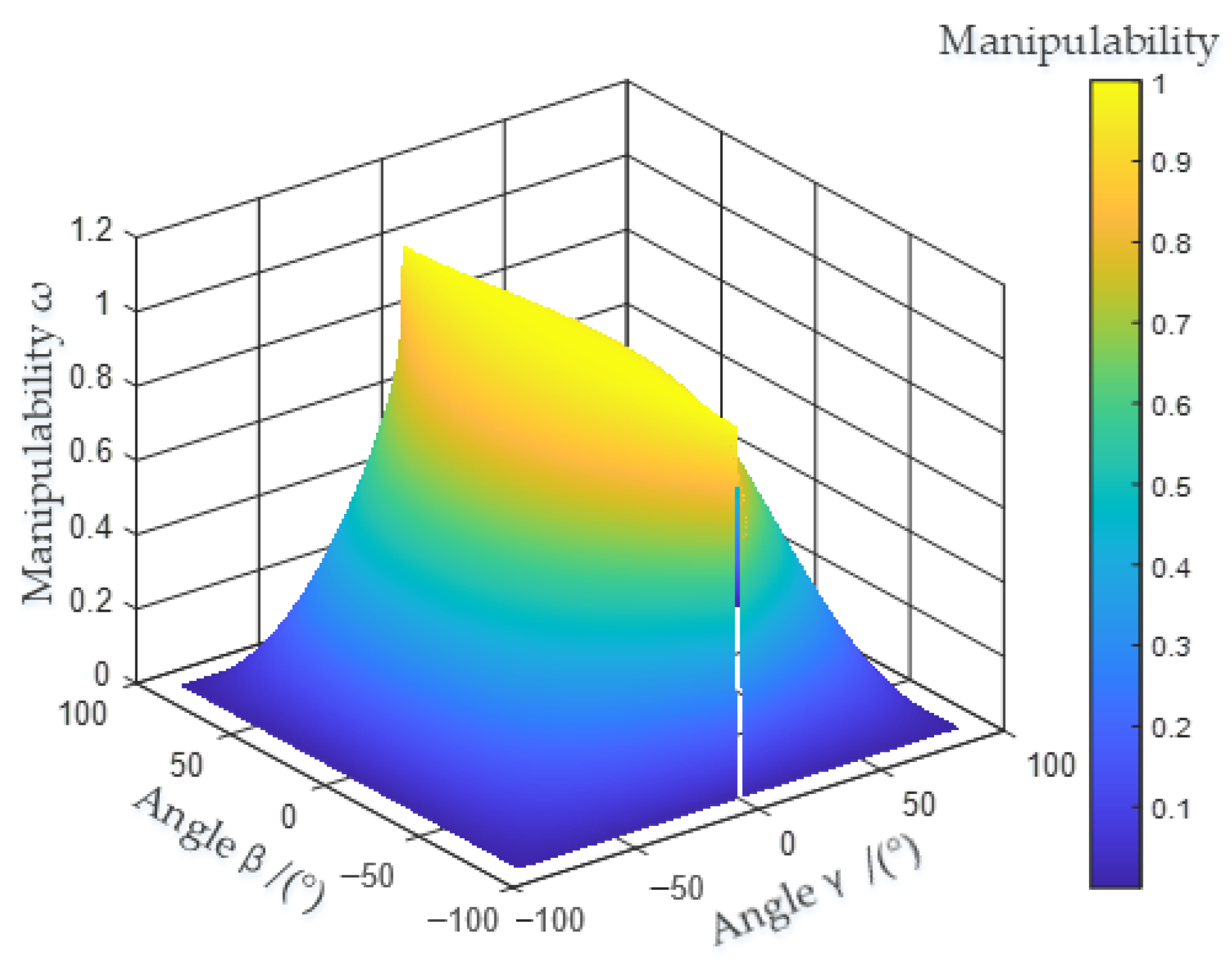
3.3. Manipulability Analysis of the Spatial 8R Mechanism
The manipulability
of the mechanism
is used to describe the comprehensive motion and overall flexibility of the mechanism in all directions. The determinant of the product of the Jacobian matrix and its transpose matrix can be defined as the metric index of robot manipulability, which is
Further, the manipulability
of this mechanism can be obtained as
The distribution of
in the workspace of −90°~90° is show in
Figure 3.
As seen in
Figure 3, the manipulability degree of (
γ,
β) near the points (−90°, −90°), (−90°, 90°), (90°, −90°) and (90°, 90°) approaches 0, and the value of
near (0,
βi) approaches infinity; thus, these positions are the singular configuration of the mechanism, where
βi represents the coordinate position on the
β axis.
Table 3 shows the extreme motion angles of abduction and adduction, forward flexion and backward extension of the hip joint during the walking gait, corresponding to the motion ranges of
γ and
β.
According to
Table 3, the boundary conditions of the
γ and
β parameters are
γ∈(−30°, 125°)
β∈(−40°, 60°)
In the above range of motion, the distribution of
in the workspace is shown in
Figure 4.
Figure 4 shows the distribution of
in the motion space, whose value ranges from 0.58 to 1.02, and the closer it is to the initial equilibrium position, the closer it is to 1. We concluded that the distribution of the manipulability
value of the mechanism is between 0.58 and 1.02, and the variation is stable and continuous in the motion space.
To sum up, manipulability is one of the kinematic performance indices of the mechanism, and the closer the value of the index is to 1, the better the movement performance of the mechanism is.
Figure 3 and
Figure 4 show that the movement performance of this spatial 8R mechanism is improved.
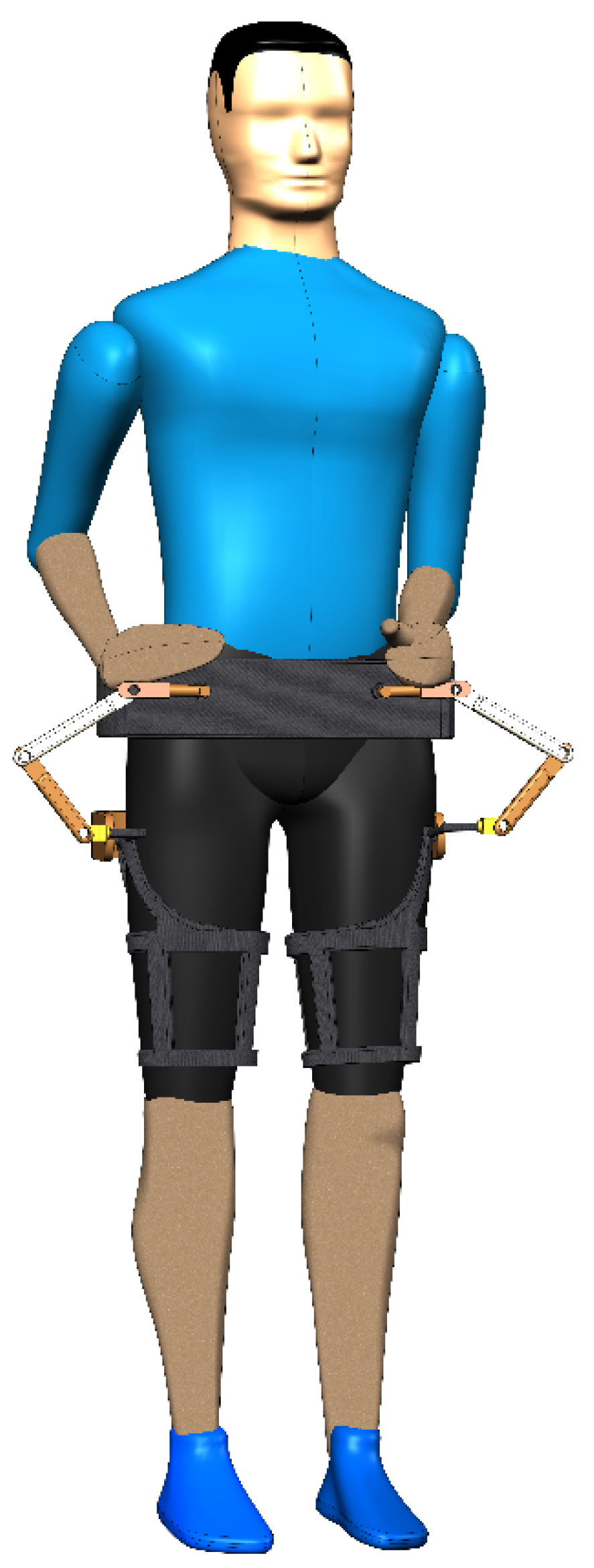
4. Analysis of Hip Joint Motion Laws
A simulation diagram of the hip joint is shown in
Figure 5. The 3D model of the mechanism was established by SolidWorks, which was imported into ADAMS software, and the corresponding kinematic pairs and drive were added to establish the virtual prototype model. The input parameters of the model are the angle parameters of its two drives. ADAMS software simulation was used to analyze the motion performance of the mechanism through the estimation of variables such as velocity, acceleration, angular velocity and angular acceleration.
The coordinate system direction in ADAMS is as follows: the
x axis is to the right along the line R
11R
21, the
y axis faces vertically up, and the
z axis is perpendicular to the
xy plane. The drive is added to R
11, R
21, R
18 and R
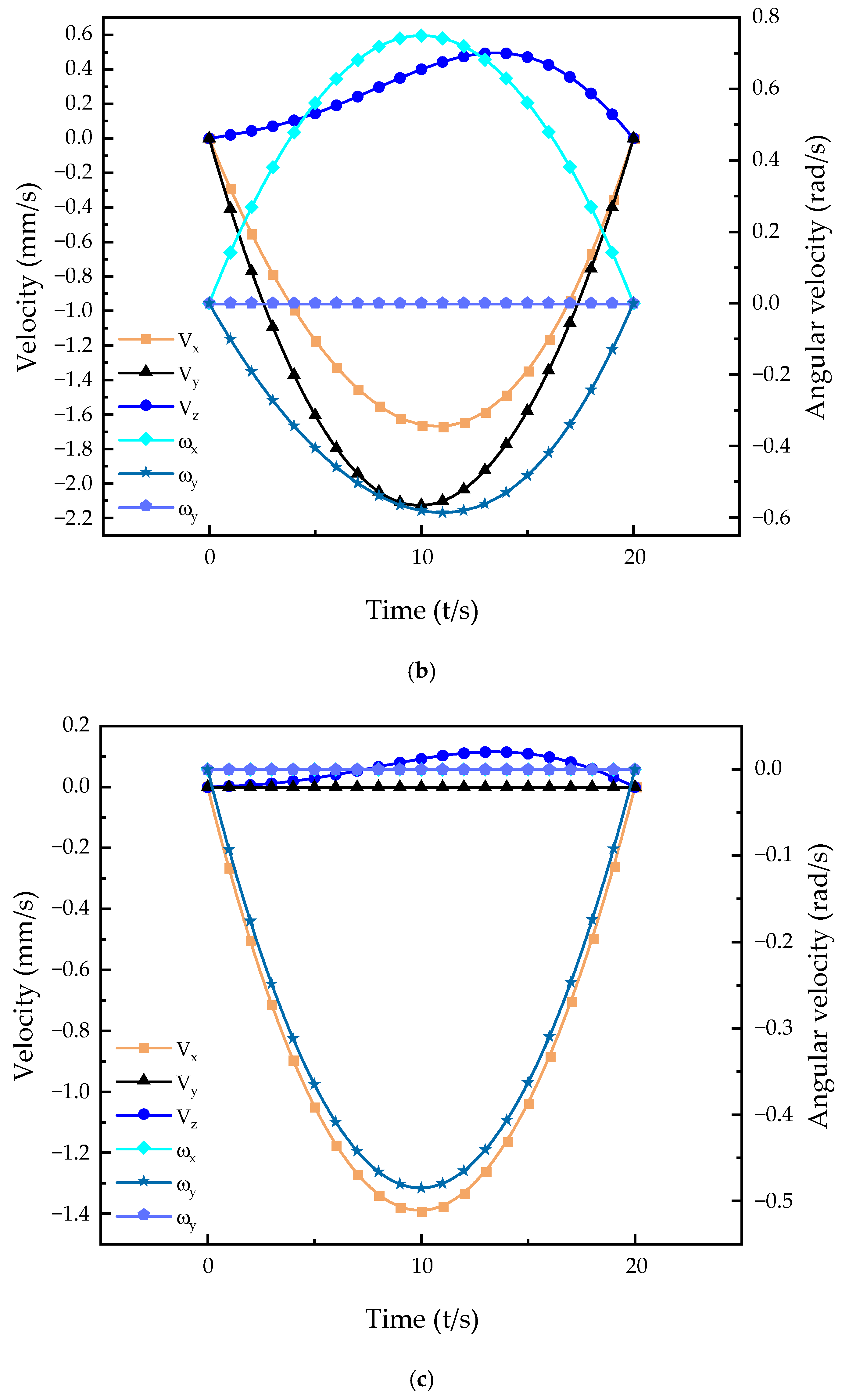
28. The forward flexion, posterior extension, abduction and adduction movements of the hip joint were simulated in ADAMS. The variations in the velocities and angular velocities of the moving platform for a single movement are shown in
Figure 6.
As seen in
Figure 5, the variation laws of various movements are relatively stable, and there is no break point, indicating that the movement performance of this mechanism is good and can be applied for hip rehabilitation. The coordinate system setting of the variation laws follow the coordinate system direction detailed in the first section, and around a certain axis, the inverse becomes positive, and the positive becomes negative. In the legend, V
x represents the velocity curve and ω
x represents the angular velocity curve. In forward flexion of the hip joint, the leg is lifted forward; thus, the velocity curve along the
y axis changes considerably, and the velocity curve along the
x axis changes as a joint linkage to ensure smoother forward flexion movement. There is no velocity in the
z axis direction, so the velocity is 0. Since the forward flexion movement rotates around the
x axis, the change in the angular velocity curve in the
x axis direction is more obvious. The change in the angular velocity curve around the
y axis is smaller than that around the
x axis, and there is no rotation around the
z axis; thus, the corresponding angular velocity curve is 0. The analysis of the velocity and angular velocity curves of other movements was carried out in the same manner. As seen in
Figure 6, the movement of this mechanism can conform to the regular motion of the human hip joint, and therefore can be used to help patients recover.
5. Conclusions
Based on various hip joint rehabilitation mechanisms, a spatial 8R mechanism with two rotational degrees of freedom was proposed. The kinematic model of the mechanism was established, and the forward/inverse kinematics of the mechanism were analyzed using the D-H method of connecting rod parameters. Using the velocity Jacobian matrix and its condition number, the mechanism was found to be completely isotropic in the single movement of abduction and adduction, forward flexion and extension, and its dexterity was determined to be excellent. By analyzing the distribution pattern of the manipulability degree of the pose of the mechanism in the range of −90°~90°, the singular configuration of the mechanism was found not to affect the normal motion of the mechanism.
According to the actual range of motion of various motion types of the human hip joint, the regular distribution of the maneuverability in the actual motion space of the hip joint is given, and its value was calculated to be distributed between 0.58 and 1.02, indicating that the mechanism has good motion characteristics. Kinematic simulation of the mechanism was carried out in ADAMS, and the velocity and angular velocity variations of the mechanism in different motion states were obtained. The kinematic performance of the mechanism was thus verified, proving the feasibility of using this mechanism for hip rehabilitation.


