Article

Suitability of an Artificial Viscosity Model for Compressible Under-Resolved Turbulence Using a Flux Reconstruction Method

School of Aeronautic Science and Engineering, Beihang University, Beijing 100191, China
*
Author to whom correspondence should be addressed.
Appl. Sci. 2022, 12(23), 12272; https://doi.org/10.3390/app122312272
Submission received: 24 October 2022 / Revised: 20 November 2022 / Accepted: 28 November 2022 / Published: 30 November 2022

Abstract

:
In the simulation of compressible turbulent flows via a high-order flux reconstruction framework, the artificial viscosity model plays an important role to ensure robustness in the strongly compressible region. However, the impact of the artificial viscosity model in under-resolved regions on dissipation features or resolving ability remains unclear. In this work, the performance of a dilation-based (DB) artificial viscosity model to simulate under-resolved turbulent flows in a high-order flux reconstruction (FR) framework is investigated. Comparison is conducted with results via several typical explicit subgrid scale (SGS) models as well as implicit large eddy simulation (iLES) and their impact on important diagnostic quantities including turbulent kinetic energy, total dissipation rate of kinetic energy, and energy spectra are discussed. The dissipation rate of kinetic energy is decomposed into several components including those resulting from explicit SGS models or Laplacian artificial viscosity model; thus, an explicit evaluation of the dissipation rate led by those modeling terms is presented. The test cases consist of the Taylor-Green vortex (TGV) problem at R e = 1600 , the freely decaying homogeneous isotropic turbulence (HIT) at M a t 0 = 0.5 (the initial turbulent Mach number ), the compressible TGV at Mach number 1.25 and the compressible channel flow at R e b = 15,334 (the bulk Reynolds number based on bulk density, bulk velocity and half-height of the channel), Mach number 1.5. The first two cases show that the DB model behaves similarly to the SGS models in terms of dissipation and has the potential to improve the insufficient dissipation of iLES with the fourth-order-accurate FR method. The last two cases further demonstrate the ability of the DB method on compresssible under-resolved turbulence and/or wall-bounded turbulence. The results of this work suggest the general suitability of the DB model to simulate under-resolved compressible turbulence in the high order flux reconstruction framework and also suggest some future work on controlling the potential excessive dissipation caused by the dilation term.

1. Introduction

The past several decades have witnessed the rapid progress of the ability to simulate aerodynamic flows via computational fluid dynamics (CFD), which is believed to bring fundamental changes to the process of aerospace design [1]. However, the application of CFD in industry is still limited by the incapacity to simulate complex turbulent flows accurately. With the evolution of computing equipment, large eddy simulation (LES), though still largely confined in academia or research and development departments of industry, has proven to be increasingly useful in a wide range of applications in recent years such as aircraft engines flow, turbine combustor flame, and flows involving turbulent transition [2,3,4]. The LES approach stands between the Reynolds Averaged Navier-Stokes (RANS) and the Direct Numerical Simulation (DNS) methods in terms of accuracy and computational cost and has shown promising feasibility for vortex dominated flows found in various aerospace applications. In an LES computation, the large scale flow structures are directly simulated while the scales below a certain resolution are approximated by an explicit subgrid scale (SGS) model or represented implicitly by the inherent numerical dissipation. The explicit SGS models are commonly categorized into three types [5,6]: the functional models, which are designed to model the action of the subgrid terms and are expected to approximately dissipate energy in the smallest scales; the structural models, which are aimed at making the best approximation of the modeled terms and are focused on representing energy transfer between various length scales; and the mixed models, which are developed by combining a functional model and a structural model together as the latter alone is generally not dissipative enough.
For the LES research a critical problem is to prevent subgrid scale models from being overwhelmed by discretization errors, if the numerical methods are not handled carefully. Previous investigation on finite volume method (FVM) concluded that the small scales of the flow might suffer from high numerical damping [7]. In terms of wave resolving, it was claimed that waves with wave lengths less than 10 times the filter width cannot be adequately resolved with a 2nd order FVM because of the large truncation error of the mesh resolution, under the assumption that the filter width corresponds to the cell size [8].
To reduce the numerical error, plenty of high order methods such as discontinuous Galerkin (DG) [9], spectral difference (SD) [10] and flux reconstruction (FR) [11] or correction procedure via reconstruction (CPR) [12] methods have been developed in the last decades and have shown great potential in LES thanks to their lower numerical dissipation as well as their capacity of handling complex geometries. These methods have multiple degrees of freedom (DOFs) defined in their computing element according to the order of accuracy and are able to reduce truncation error if the order is set high enough, it is also possible for these methods to resolve shorter waves in the LES solution since their DOFs per wave (DPW) increase [8]. Plenty of successful and encouraging works including wall-modeled turbulence and transition have appeared in the literature [6,13,14,15,16,17,18,19,20]. Among the aforementioned high order methods, the FR method provides a general high-order framework, which recovers the collocation-based nodal DG and SD methods in case of linear fluxes and also sets a path for new schemes. The FR approach is further developed into a family of energy-stable flux reconstruction (ESFR) schemes [21], whose stability has been proved for multiple types of elements [22,23,24]. It has been found that the FR approach is more computationally efficient than conventional lower order methods [25]. For simulations of turbulent flows, implicit LES using the FR approach on canonical testcases such as isentropic vortex advection [26], the Taylor-Green vortex, turbulent channel flow and transitional flow [6] has presented satisfying results, while explicit SGS models may be still in need for under-resolved flows, where the aliasing error can impact the robustness [27].
For simulation of compressible turbulence via high order methods, another computational challenge is to resolve shock waves. Shock-capturing schemes, which are mostly relied on to represent shock waves, can be generally classified into two types. The first approach involves a nonlinear limiter to detect shock waves and control oscillations near them, such as total variation bounded (TVB) type slope limiters [28,29], moment limiters [30,31,32] and the weighted essentially non-oscillatory (WENO) type schemes [33,34]. Another approach is adding to the governing equations an artificial diffusion term, which is expected to smear the shocks at discontinuities over a numerically resolvable scale and vanish in the smooth region. The advantages of the artificial diffusion term is the simple formulation, ease of implementation, and low computational cost.
In the context of LES, an adaptive approach was proposed by Cook et al. [35] to handle shocks and turbulence simultaneously by employing an artificial bulk viscosity and an artificial shear viscosity. A simple modification was proposed by Mani et al. [36], which replaced the strain rate tensor based artificial bulk viscosity by a dilation based counterpart. The modified version by Mani et al. [36] also applied a switch function to further localize the bulk viscosity to regions surrounding the shocks. Recently a simplified form of the artificial bulk viscosity model was presented by Yu et al. [37] and was shown to achieve good balance between accuracy and robustness. In this paper, this simplified form, referred to as dilation-based (DB) model, is adopted to take advantage of its analytical form in governing equations.
An important issue about LES method is that the computations are not well resolved, in other word, under-resolved because the scales smaller than the resolution, which is associated to Nyquist wavenumber of the grid, cannot be captured [38]. Thus for LES of compressible turbulence the following essential under-resolved features may arise [5]. First, for flows free from shocks, the turbulent structures under subgrid scales (SGS) are accounted for by implicit or explicit SGS models, which may be originally designed for incompressible flows and then directly extended to variable-density cases. This extension is expected to be sufficient for their respective original purpose, though the underlying dynamic mechanism about the nonlinear transfer of kinetic energy between the scales of motion may be altered by the compressibility effects. Second, for flows with shocks or other sharp features [39], additional numerical dissipation is required for stability purposes, which reduces the range of well-resolved scales in LES [40]. Such shock-capturing methods may also bring unphysical dissipation into the smooth turbulent regions and thus should be handled carefully. Moreover, for under-resolved computation, the behavior of high order methods is not as clear as that for the well resolved cases because the order of convergence is defined as cell size tending to zero, while under-resolved computation means relatively larger cell size [41]. To sum up, despite the tremendous works on LES of compressible turbulence via high order methods, the relative roles of the SGS models, the shock-capturing schemes and the high order spatial discretization methods on dissipation property and resolving ability remain unclear.
In this study, we focused on the performance of the DB artificial viscosity in the context of LES on compressible turbulence via high order flux reconstruction method and compared the DB model with several typical explicit SGS models as well as implicit LES. First, two test cases, the Taylor-Green vortex (TGV) problem at R e = 1600 and freely decaying homogeneous isotropic turbulence (HIT) at M a t 0 = 0.5 , are weakly compressible to demonstrate the performance of the DB model in largely smooth regions. The effects of simulation methodology on concerning diagnostic quantities such as the turbulent kinetic energy, the total dissipation rate of kinetic energy and so on are discussed. The exact dissipation resulting from explicit SGS models or Laplacian artificial viscosity model is derived, presenting a detailed decomposition of the total dissipation rate of kinetic energy. For a further investigation of the DB model in flows with stronger compressible effects, the compressible TGV problem at M a = 1.25 simulated by Lusher et al. [42] and the compressible channel flow at M b = 1.5 and R e b = 15,334 based on height of the channel are investigated on high order method with coarse meshes. General agreement with the DNS results is observed.
This paper is organized as follows. In Section 2 the numerical methods are presented, including a brief introduction of the governing equations, the FR/CPR method, the explicit SGS models and the artificial viscosity model. The numerical results for each testcase are discussed in Section 4.1, Section 4.2, Section 4.3 and Section 4.4, respectively. Then the conclusions are summarized in Section 5.

2. Numerical Methods

2.1. Governing Equations

This work solves the compressible Navier-Stokes equations of an ideal gas in 3D, with Laplacian artificial viscosity and zero bulk viscosity, which are written in Favre filtered form as follows:
ρ ¯ t + · ( ρ ¯ u ˜ ) = · ( μ a v ρ ¯ ) ,
( ρ ¯ u ˜ ) t + · ( ρ ¯ u ˜ u ˜ ) + p ¯ · σ ^ = · ( μ a v ( ρ ¯ u ˜ ) ) · τ s g s + · ( σ ¯ σ ^ ) , ρ ¯ e ˜ t + · ( ρ ¯ u ˜ e ˜ ) + · ( p ¯ u ˜ ) · ( σ ^ · u ˜ ) + · q ^
= · ( μ a v ( ρ ¯ e ˜ ) ) · q s g s + · ( σ · u ¯ σ ^ · u ˜ ) · ( q ¯ q ^ ) ,
with
p ¯ = ( γ 1 ) ρ e ¯ 1 2 ρ ¯ u ˜ · u ˜ , σ ^ = 2 μ ˜ S ˜ 2 3 μ ˜ δ ( · u ˜ ) , S ˜ = 1 2 u ˜ + ( u ˜ ) T , μ ˜ ( T ˜ ) = μ r e f T ˜ T r e f 3 / 2 T r e f + T s T ˜ + T s , q ^ = k ˜ T ˜ , T ˜ = p ¯ ρ ¯ R , k ˜ = μ ˜ C P Pr ,
where ( · ) ¯ , ( · ) ˜ stand for a low-pass filtering operator and the Favre-filter operator ( φ ˜ = ρ φ ¯ / ρ ¯ , for any quantity φ ), respectively, ρ is density, u the velocity vector, e the total energy per unit mass, the filtered pressure p ¯ is computed by the usual ideal gas equation of state, γ = C P / C V is the ratio between specific heat capacities at constant pressure and constant volume, σ ^ is the resolved viscous stress tensor with S ˜ being the Favre-filtered strain-rate tensor, δ is the unit tensor, q ^ is the resolved heat fluxes dominated by Fourier’s law, μ ˜ and k ˜ are the corresponding dynamic viscosity and thermal conductivity of the fluid at the filtered temperature T ˜ , Pr is the Prandtl number and R is the gas constant, in this paper, γ = 1.4 and P r = 0.72.
The first terms in the right-hand side of Equations (1)–(3) are the Laplacian artificial viscosity terms and are presented in detail in Section 2.4. In the right-hand side of momentum equation, τ s g s = ρ ¯ ( u u ˜ u ˜ u ˜ ) is the Favre-averaged subgrid scale stress. Note that the difference between σ ¯ and σ ^ is usually neglected [43]. In the right-hand side of energy equation, q s g s is the subgrid total energy flux vector defined as
q s g s = ( ρ e + p ) u ¯ ( ρ e ¯ + p ¯ ) u ˜ .
The third and fourth terms in the right-hand side of the energy Equation (3) are viscous dissipation and heat diffusive subgrid contributions which can be neglected [44]. The explicit SGS modeling of τ s g s and q s g s is presented in detail in Section 2.3.
In this study, the explicit SGS models and the artificial viscosity are not applied simultaneously, leading to three types of methodologies for a single simulation: LES with explicit SGS models, LES with artificial viscosity and implicit LES (iLES) without any model at all.

2.2. Flux Reconstruction Method

In the FR approach, first the computational domain Ω is divided into N non-overlapping elements Ω h , h = 1 , , N . Taking non-uniformity into consideration, a coordinate transformation is applied to map the physical coordinates x = ( x , y , z ) to the computational coordinates ξ = ( ξ , η , ζ ) in a standard hexahedral computational element Ω h = [ 1 , 1 ) 3 . The transformation Jacobian matrix J is defined as J i j = x i / ξ j . Then for the following governing equations:
U t + · F = 0 ,
the transformed governing equations take the following form:
U ^ t + ^ · F ^ = 0 ,
where
U ^ = | J | U , F ^ = | J | J 1 F , ^ = ( / ξ , / η , / ζ ) .
In the standard computational element, a set of points (solution points, SPs) are defined, on which the values of the flow field are stored and updated by solving the equations above. In this paper, the SPs are located at the Legendre-Gauss points. By adopting N p solution points, for example, in ξ direction, the 1-D Lagrange basis polynomial of N p 1 degree is
l i ( ξ ) = j = 1 , j i N p ξ ξ j ξ i ξ j , i = 1 , , N p .
Once given the values at the SPs, the solution U ^ in the standard computational element Ω h is approximated by U h ^ , which is reconstructed by a tensor product of the three polynomials in ξ , η and ζ direction, respectively:
U ^ h ( ξ , η , ζ ) = k = 1 N p j = 1 N p i = 1 N p U ^ h | i , j , k · l i ( ξ ) · l j ( η ) · l k ( ζ ) ,
where U ^ h | i , j , k is the current value of the approximation function of solution at SP located by ( i , j , k ) in the computational element Ω h .
Next, the polynomials of fluxes are constructed for time advancement of the solution in element Ω h . First, the discontinuous polynomials of fluxes in each element are constructed:
F ^ h D = { f ^ h D , g ^ h D , h ^ h D } , f ^ h D ( ξ , η , ζ ) = k = 1 N p j = 1 N p i = 1 N p f ^ h | i , j , k · l i ( ξ ) · l j ( η ) · l k ( ζ ) , g ^ h D ( ξ , η , ζ ) = k = 1 N p j = 1 N p i = 1 N p g ^ h | i , j , k · l i ( ξ ) · l j ( η ) · l k ( ζ ) , h ^ h D ( ξ , η , ζ ) = k = 1 N p j = 1 N p i = 1 N p h ^ h | i , j , k · l i ( ξ ) · l j ( η ) · l k ( ζ ) ,
where superscript D denotes discontinuous, f ^ h | i , j , k , g ^ h | i , j , k , h ^ h | i , j , k are the current value of the approximation fuction of flux at SP located by ( i , j , k ) in the computational element Ω h , along ξ , η and ζ direction, respectively. Note that the polynomials f ^ h D , g ^ h D , h ^ h D are piecewise and might not be continuous across the interfaces between the elements. In the FR approach, the discontinuous polynomials of fluxes are then made continuous by introducing correction functions. The corrected fluxes are then defined as:
F ^ h C = { f ^ h C , g ^ h C , h ^ h C } , f ^ h C ( ξ , η , ζ ) = ( f ^ h L ( η , ζ ) f ^ h D ( 1 , η , ζ ) ) g L ( ξ ) + ( f ^ h R ( η , ζ ) f ^ h D ( 1 , η , ζ ) ) g R ( ξ ) , g ^ h C ( ξ , η , ζ ) = ( g ^ h L ( ξ , ζ ) g ^ h D ( ξ , 1 , ζ ) ) g L ( η ) + ( g ^ h R ( ξ , ζ ) g ^ h D ( ξ , 1 , ζ ) ) g R ( η ) , h ^ h C ( ξ , η , ζ ) = ( h ^ h L ( ξ , η ) h ^ h D ( ξ , η , 1 ) ) g L ( ζ ) + ( h ^ h R ( ξ , η ) h ^ h D ( ξ , η , 1 ) ) g R ( ζ ) ,
where ( · ) ^ h L and ( · ) ^ h R denote the interface fluxes via a Riemann solver, g L and g R are left and right correction functions satisfying boundary conditions that
g L ( 1 ) = 1 , g L ( 1 ) = 0 ,
and
g R ( 1 ) = 0 , g R ( 1 ) = 1 .
In this paper, the left and right Radau polynomials are chosen as correction functions g L and g R , respectively. Those correction functions are denoted by g D G [11] because they recover the standard DG scheme. This scheme is referred to as FR-DG. In terms of Riemann solver, the 3D Roe-Pike [45] method and the compact DG ( CDG ) [46] method are applied to calculate inviscid and viscous common interface fluxes, respectively. The strong stability preserving five-stage fourth-order Runge-Kutta (SSPRK54) [47] is adopted for explicit time integration in the numerical experiments in this paper.

2.3. Subgrid Scale Models

In this work, two explicit subgrid-scale (SGS) models are employed: the standard Smagorinsky model [48] and the Similarity model [49]. These explicit SGS models are briefly presented by categories for clarity as follows.

2.3.1. Functional Models

The functional SGS models focus on modeling the action of the subgrid terms and bringing a similar effect [5]. Based on the eddy-viscosity concept, the subgrid stress tensor and the subgrid total energy flux vector of the functional SGS models are given as follows:
τ i j s g s = 2 μ s g s ( S ˜ i j 1 3 δ i j S ˜ k k ) ,
q j s g s = k s g s T ˜ x j , k s g s = μ s g s C P Pr s g s ,
where Pr s g s = 0.5 is the subgrid Prandtl number.
In the standard Smagorinsky model, μ s g s is given by:
μ s g s S = ρ ˜ C S 2 Δ 2 2 S ˜ i j S ˜ i j ,
where S ˜ i j is the resolved strain rate tensor defined in Equation (4), C S = 0.1 is the Smagorinsky coefficient and Δ is the filter width given by Δ = s · h / ( P + 1 ) , where s is a scaling factor set to 2, h is the characteristic grid size and P is the order of the solution polynomial. This expression of Δ means that Δ = h for p 1 solution polynomial and Δ = h / 2 for p 3 solution polynomial, which follows the assumption that the filter width corresponds to the cell size estimated from the DOFs.

2.3.2. Structural Models

The velocity can be decomposed into u i = u ˜ i + u i , where u ˜ i and u i stand for resolved and unresolved parts. Then the subgrid stress tensor can be rewritten as
τ i j s g s = L i j + C i j + R i j ,
where
L i j = ρ ¯ u ˜ i u ˜ j ˜ ρ ¯ u ˜ i u ˜ j ,
C i j = ρ ¯ u ˜ i u j ˜ + ρ ¯ u i u ˜ j ˜ ,
R i j = ρ u i u j ¯ ,
are the Leonard stresses, the cross terms and the SGS Reynolds stresses, respectively. According to the scale-similarity hypothesis [49], the cross terms and the Reynolds stresses are approximated as
C i j ρ ¯ [ u ˜ ˜ i ( u ˜ j u ˜ ˜ j ) + u ˜ ˜ j ( u ˜ i u ˜ ˜ i ) ] ,
R i j ρ ¯ ( u ˜ i u ˜ ˜ i ) ( u ˜ j u ˜ ˜ j ) .
Then the subgrid stress tensor can be written as the following approximation:
τ i j s g s ρ ¯ u ˜ i u ˜ j ˜ ρ ¯ u ˜ i u ˜ j + ρ ¯ u ˜ i u ˜ j ρ ¯ u ˜ ˜ i u ˜ ˜ j = ρ ¯ u ˜ i u ˜ j ˜ ρ ¯ u ˜ ˜ i u ˜ ˜ j .
The subgrid total energy flux vector can be written as [44]:
q j s g s = γ ρ ¯ ( e ˜ I u ˜ j ˜ e ˜ ˜ I u ˜ ˜ j ) ,
where e ˜ I is the resolved internal energies:
e ˜ I = ρ e ¯ ρ ¯ 1 2 u ˜ k u ˜ k .

2.4. Artificial Viscosity

The artificial viscosity adopted in this paper is based on Laplacian dissipative terms in Equations (1)–(3) given by the following form:
· ( μ a v φ ) ,
where φ denotes the conserved variable, μ a v is the artificial viscosity. In this work, μ a v is modeled via the dilation-based (DB) artificial viscosity method presented in [37] and is computed as follows:
μ β = c β | · u ˜ | ( h / P ) 2 ,
where u = ( u , v , w ) denotes velocity vector, c β is an empirical parameter, h is the characteristic grid size, P is the order of the approximation polynomials of solution. The DB method takes the dilation as the shock sensor, which is easy to implement and of low computational cost. In addition, an upper limit is given as follows:
μ m a x = c m a x ( h / P ) max x S h | λ ( x , t ) | ,
where c m a x is an empirical parameter, S h stands for the solution points within element Ω h , λ ( x , t ) is the local wave speed. Thus, the final artificial viscosity is:
μ a v = m i n ( μ β , μ m a x ) .
For all testcases in this work, the empirical parameters are set as c β = 1 and c m a x = 0.5 , which follow the baseline values suggested by [37].

3. Decomposition of Total Turbulent Energy Dissipation Rate

In this paper, we conducted a detailed derivation of turbulent kinetic energy equation and a thorough decomposition of the dissipation rate of kinetic energy in the context of the compressible Navier-Stokes equations with modeling terms including explicit SGS modeling terms or Laplacian artificial viscosity terms. This is an extended work based on [50], which did not take any modeling term into consideration. First, the mass and momentum equations of the Navier-Stokes equations are rewritten as follows:
ρ ¯ t + · ( ρ ¯ u ˜ ) · ( μ a v ρ ¯ ) = 0 ,
( ρ ¯ u ˜ ) t + · ( ρ ¯ u ˜ u ˜ ) + p ¯ · σ ^ + · τ s g s · ( μ a v ( ρ ¯ u ˜ ) ) = 0 .
These equations are exactly the governing Equations (1) and (2) without the neglectable terms. Considering the mass Equation (31), the momentum Equation (32) is transformed into following form:
ρ ¯ u ˜ t + ρ ¯ u ˜ · ( u ˜ ) + p ¯ · σ ^ + · τ sgs · ( μ a v ( ρ ¯ u ˜ ) ) + u ˜ · ( · ( μ a v ρ ¯ ) ) = 0 .
By multiplying the momentum equation above by u ˜ , we obtain a conservation equation for the turbulent kinetic energy defined by e ˜ k = 1 2 u ˜ · u ˜ :
ρ ¯ e ˜ k t + u ˜ · ( ρ ¯ u ˜ · ( u ˜ ) ) + u ˜ · ( p ¯ ) u ˜ · ( · σ ^ ) + u ˜ · ( · τ sgs ) u ˜ · · ( μ a v ( ρ ¯ u ˜ ) ) + u ˜ · u ˜ · ( · ( μ a v ρ ¯ ) ) = 0 .
The above equation integrated on arbitrary domain Ω reads
Ω ρ ¯ e ˜ k t d Ω 1 + Ω u ˜ · ( ρ ¯ u ˜ · ( u ˜ ) ) d Ω 2 + Ω u ˜ · ( p ¯ ) d Ω 3 Ω u ˜ · ( · σ ^ ) d Ω 4 + Ω u ˜ · ( · τ sgs ) d Ω 5 Ω u ˜ · · ( μ a v ( ρ ¯ u ˜ ) ) d Ω 6 + Ω u ˜ · u ˜ · ( · ( μ a v ρ ¯ ) ) d Ω 7 = 0 .
By using partial integration and considering mass Equation (31) again, the first term in Equation (35) can be written as
Ω ρ ¯ e ˜ k t d Ω = Ω t ( ρ ¯ e ˜ k ) d Ω Ω e ˜ k ρ ¯ t d Ω = Ω t ( ρ ¯ e ˜ k ) d Ω + Ω e ˜ k ( · ( ρ ¯ u ˜ ) ) d Ω Ω e ˜ k ( · ( μ a v ρ ¯ ) ) d Ω .
The second to fifth terms are rewritten as below using partial integration and periodicity:
Ω u ˜ · ( ρ ¯ u ˜ · ( u ˜ ) ) d Ω = Ω ρ ¯ u ˜ · ( e ˜ k ) d Ω = Ω e ˜ k ( · ( ρ ¯ u ˜ ) ) d Ω ,
Ω u ˜ · ( p ¯ ) d Ω = Ω p ¯ ( · u ˜ ) d Ω ,
Ω u ˜ · ( · σ ^ ) d Ω = Ω ( u ˜ ) : σ ^ d Ω ,
Ω u ˜ · ( · τ sgs ) d Ω = Ω ( u ˜ ) : τ s g s d Ω .
The sixth and seventh terms as well as the last term in the right-hand side of Equation (36) are dominated by the artificial viscosity and are simplified by again using partial integration and periodicity as below:
Ω e ˜ k ( · ( μ a v ρ ¯ ) ) d Ω last term in 1 Ω u ˜ · · ( μ a v ( ρ ¯ u ˜ ) ) d Ω 6 + Ω u ˜ · u ˜ · ( · ( μ a v ρ ¯ ) ) d Ω 7 = Ω e ˜ k ( · ( μ a v ρ ¯ ) ) d Ω Ω u ˜ · · ( μ a v ( ρ ¯ u ˜ ) ) d Ω = Ω μ a v ρ ¯ ( u ˜ : u ˜ ) d Ω .
From Equations (36)–(41), we have
t Ω ( ρ ¯ e ˜ k ) d Ω = Ω p ¯ ( · u ˜ ) d Ω + Ω ( u ˜ ) : σ ^ d Ω Ω ( u ˜ ) : τ s g s d Ω + Ω μ a v ρ ¯ ( u ˜ : u ˜ ) d Ω .
The second term in the right-hand side of the above equation is the viscous contribution and can be further expressed [50,51] as below:
Ω ( u ˜ ) : σ ^ d Ω = Ω 2 μ ˜ u ˜ : S ˜ d d Ω = Ω 2 μ ˜ S ˜ d : S ˜ d d Ω = Ω 4 3 μ ˜ ( · u ˜ ) 2 d Ω + Ω μ ˜ w ˜ · w ˜ d Ω ,
where w ˜ = × u ˜ is the resolved vorticity vector, S ˜ d is the deviatoric part of the strain rate tensor. According to Equations (42) and (43), the equation for the turbulent kinetic energy is finally given in volume-averaged form as below:
t ρ ¯ e ˜ k = p ¯ ( · u ˜ ) + 4 3 μ ˜ ( · u ˜ ) 2 + μ ˜ w ˜ · w ˜ ( u ˜ ) : τ s g s + μ a v ρ ¯ ( u ˜ : u ˜ ) ,
namely
ϵ t o t a l = d E k d t = ϵ d + ϵ c + ϵ s + ϵ s g s + ϵ a ,
where
E k = ρ ¯ e ˜ k = 1 2 ρ ¯ u ˜ · u ˜ , ϵ d = p ¯ ( · u ˜ ) , ϵ c = 4 3 μ ˜ ( · u ˜ ) 2 , ϵ s = μ ˜ w ˜ · w ˜ , ϵ s g s = ( u ˜ ) : τ s g s , ϵ a = μ a v ρ ¯ ( u ˜ : u ˜ ) ,
where · denotes a volume average over the computational domain. ϵ t o t a l is time derivative of the total volume-averaged kinetic energy E k , ϵ d is pressure-dilation transfer, ϵ c and ϵ s are the compressible and solenoidal dissipation, respectively. ϵ s g s and ϵ a are the dissipation caused by the explicit SGS models and artificial viscosity, respectively.
Note that ϵ s g s and ϵ a are not applied simultaneously in a single simulation, the sum of the components of the dissipation in different types of simulation, denoted by ϵ , is given for clarity:
ϵ = ϵ d + ϵ c + ϵ s , for implicit LES , ϵ d + ϵ c + ϵ s + ϵ s g s , for explicit LES , ϵ d + ϵ c + ϵ s + ϵ a , for LES with artificial viscosity .
The derived dissipation ϵ is expected to be generally identical to the overall dissipation ϵ t o t a l , which is calculated directly from the total volume-averaged kinetic energy E k . With the components of ϵ explicitly expressed in Equation (47), the remaining gap between ϵ t o t a l and ϵ is the residual dissipation resulted from the truncation error of the numerical scheme in the explicit estimated terms, which is expressed as:
ϵ r e s = ϵ t o t a l ϵ .

4. Results and Discussion

4.1. Incompressible Taylor-Green Vortex

The Taylor-Green vortex (TGV) [52] is a canonical three-dimensional flow problem which contains transition to anisotropic small-scale turbulence and subsequent decay [50]. The TGV problem is simulated in a triple periodic cube Ω = [ 0 , 2 π ) 3 , starting from the initial condition as follows:
ρ = ρ 0 , u = V 0 s i n x L c o s y L c o s z L , v = V 0 c o s x L s i n y L c o s z L , w = 0 , p = p 0 + ρ 0 V 0 2 16 c o s 2 x L + c o s 2 y L c o s 2 z L + 2 ,
where ρ , ( u , v , w ) and p denote density, velocity vector and pressure, respectively, ρ 0 , V 0 and L are reference density, velocity and length and are all set to 1.0. The characteristic convective time is defined as t c = L / V 0 . The physical duration of the computation is set to t f i n a l = 20 t c . The initial Reynolds number is defined as R e 0 = ρ 0 V 0 L / μ and is set to 1600. The Mach number is set to M 0 = V 0 / c 0 = 0.1 , with c 0 = γ p 0 / ρ 0 being the speed of sound, where γ is set to 1.4 and the initial pressure p 0 is adjusted to ensure M 0 = 0.1 . The simulation is conducted using FR-DG scheme on uniform Cartesian grids of 120 3 degrees of freedom (DOFs) discretized by a coarse mesh of 30 3 elements with third-order solution polynomial ( p 3 ) and a finer mesh of 60 3 elements with first-order solution polynomial ( p 1 ). This resolution leads to a purposely under-resolved simulation for investigation of the impact of the methodologies applied in this paper.
Figure 1, Figure 2, Figure 3 and Figure 4 display the time evolution of E k , ϵ t o t a l and components of ϵ of the Taylor-Green vortex simulation. The additional modeling dissipation terms, ϵ s g s and ϵ a , are plotted in Figure 5. A DNS result of E k , ϵ s and ϵ d computed by Debonis [53] via the 13-point dispersion-relation-preserving (DRP) scheme [54] on 512 3 elements is taken as reference in Figure 1, Figure 2, Figure 3 and Figure 4. Note that at the DNS solution ϵ s is accurate enough to be plotted as a reference for the total dissipation rate ϵ t o t a l . The contribution of the compressible dissipation ϵ c is neglectable in this testcase and therefore not plotted here. In the following paragraphs, the effects of polynomial order and modeling terms on dissipative property, the energy spectra, and the computational cost are discussed in detail.

4.1.1. Effects of Polynomial Orders

First, the effects of the solution polynomial order on dissipative property are discussed. Figure 1 and Figure 2 illustrate a general overview of the dissipative evolution of the TGV testcase. It can be observed that in the p 1 results, all solutions deviate from the reference due to larger overall dissipation. The results of overall dissipation rate at p 1 are all larger than their p 3 counterpart, which also indicates the stronger overall dissipation at lower order. Figure 3 plots the solenoidal dissipation ϵ s , which is a measure of numerical accuracy and ability to resolve small vortices scales [55]. Results of solenoidal dissipation at p 1 are apparently lower that those at p 3 regardless of the simulation methodologies. It is clear that the vorticity-carrying small scales are not well resolved on the lower solution polynomial order because the sharpness of resolved derivatives is severely reduced, though the DOFs are the same. The pressure dilation dissipation ϵ d , plotted in Figure 4 with the y-axis scale stretched, is supposed to be two-orders of magnitude smaller than the total dissipation rate since the Mach number of this testcase is so low. According to the DNS results, the very low level of pressure dilation dissipation ϵ d , compared with the total dissipation rate, confirms the incompressible flow assumption though the simulation is compressible. This feature of the pressure dilation dissipation could serve as some evaluation of the error of numerical method when simulating incompressible flows via a compressible solver. In Figure 4, the ϵ d at p 1 deviates from the reference at the initial time moment, while the p 3 solution agrees well with the reference until the flow becomes under-resolved. The peak values of ϵ d decrease as the solution order increases. Similar phenomenon is observed in [56] and is reported to converge to the ideal solution with grid refinement.
Figure 5 shows the evolution of modeling dissipation terms, ϵ s g s and ϵ a . Later peaks and higher levels of SGS modeling dissipation are observed at p 3 , which result from the improved resolution of the velocity gradients. However, for the DB model, later peak but lower level of modeling dissipation is observed at p 3 . This opposite behavior of the DB model is due to its inherent sensitiveness to dilation term, as defined in Equation (28). It can be inferred from Figure 4 that at p 1 solution order, the error between the dilation term and ideal zero is larger than p 3 , leading to higher level of ϵ a . This decrease of precision caused by larger error of dilation at lower solution polynomial order was also reported in [37] for weakly compressible flow.
The 3D energy spectra at time t = 9 are plotted on a log-log scale in Figure 6. At this time, the slope of the energy spectra reaches the Kolmogorov value –5/3 and the dissipation rate reaches peak value. A reference solution via pseudo-spectral method on a 512 3 grid [50] is plotted for comparison. The effects of the solution polynomial order is evident. It can be observed that the p 1 simulations hardly recover the reference slope and deviates at very low wavenumber, p 3 simulations produce more reasonable energy spectra. The p 3 results also deviate from the reference at high wavenumber, which is normal in consideration of the insufficient resolution.
To sum up, simulations at p 3 order produce more accurate results, better resolution of small scales and significantly lower numerical error though the simulation is under-resolved. Higher order representation of the solution are also superior at resolving energy of the small scales. The explicit SGS models and the DB artificial viscosity model, though built in different manner, all benefit from more accurate resolution of velocity gradients produced by higher order of solution polynomial. Another benefit brought by higher order scheme is that the general trend and peak values of the model dissipation are more reasonable, as shown in Figure 5.

4.1.2. Effects of the Explicit SGS Models and the DB Model

The evolution of modeling dissipation terms, ϵ s g s and ϵ a are shown in Figure 5. The impact of the explicit SGS models and the DB model is investigated in the following discussion, which focuses on the p 3 results in Figure 2b and Figure 5b because they are less affected by the numerical error. Before t = 4 , the under-resolved scales are not developed in the flow, it can be observed in Figure 5b that all models produce very low dissipation. From then on the flow turns under-resolved and the modeling dissipation arises significantly and reaches the peak around 8 < t < 9 . As shown in Figure 2b, during the under-resolved phase, all models bring apparent extra dissipation, which can be majorly described by ϵ s g s and ϵ a derived in Section 3. Among the SGS models, the similarity model is less dissipative than the Smagorinsky model, as expected. The DB model produces close dissipation to the similarity model, but with lower ϵ a before t = 4 , and sharper peak around 8 < t < 9 as shown in Figure 5b. Similar trend of dissipation property can also be observed in results of the energy spectra plotted in Figure 6b. From the view of ϵ t o t a l in Figure 2b, the iLES method agrees well with the reference during 0 < t < 8 but produces lower peak value when the smallest turbulent structures occur. The DB model has the potential to improve the insufficient dissipation, with slightly extra dissipation since t = 4 , when the flow turns under-resolved.

4.1.3. Discussion on Computational Cost

In this section the computational cost of the various methodologies in this test case is compared. Table 1 shows the runtime cost of the incompressible TGV problem presented here. Multiple runs were performed and an average value of the runtime is given. Ratio values are computed based on the averaged runtime of the iLES approach with discretization being 30 3 elements and p 3 solution polynomial order. These test cases run on a CPU-based platform, with an Intel E5-2680 V3 node, which consists of 24 cores. Table 1 shows that the p 3 schemes are slightly more computationally efficient than their p 1 counterparts. It can be observed that when higher order discretization is applied, under the same DOFs, the computational cost is reduced by about 7% for iLES, DB and similarity simulations and 10% for Smagorinsky simulation. An explanation may be that fewer elements in higher order computation reduces the number of interfaces, which affects the cost of interface communication. The explicit SGS models both lead to extra cost compared to the iLES computation. This trend is reasonable because these models both call for extra calculations on SGS terms. The cost of the DB model is less than the explicit SGS models because of its more simple terms.

4.2. Homogeneous Isotropic Turbulence

The freely decaying homogeneous isotropic turbulence (HIT) is a fundamental case for investigation of the physical properties of turbulence and an ideal configuration for measuring the ability of numerical method to reproduce the fundamental properties of turbulence. The simulation is conducted in a triple periodic cube Ω = [ 0 , 2 π ) 3 where the velocity field is initially generated from a given spectrum via the approach of Rogallo [57]. The energy spectrum is expressed as follows:
E ( k ) = 16 3 2 π M t 0 2 k 4 k 0 5 e 2 k 2 / k 0 2 ,
where k is the wavenumber, M t 0 the turbulent Mach number at t = 0, k 0 the wavenumber at the peak of the energy spectrum, taken as k 0 = 8.0 in this work. The physical duration of the computation is set to 5 τ , where τ is the initial large-eddy-turnover time. The initial density and pressure fields are set uniformly, which means that no fluctuations of any thermodynamic quantities is in the initial field. The methodologies of computation is identical to the TGV case, namely, a p 1 solution polynomial on a finer mesh of 60 3 elements and a p 3 solution polynomial on a coarse mesh of 30 3 elements.
In addition to the total volume-averaged kinetic energy E k , its time derivative ϵ t o t a l as well as the various components of ϵ , more statistical quantities of concern are defined and addressed as follows.
The turbulent Mach number M a t and Taylor Reynolds number R e λ are defined as follows [51]:
M a t = 3 u r m s c ,
R e λ = u r m s λ ρ μ ,
where
u r m s = u 2 + v 2 + w 2 3 ,
λ = u r m s 2 ( u / x ) 2 ,
is the turbulent fluctuating velocity and the Taylor microscale, respectively, c stands for speed of sound, · denotes a volume average over the computational domain at a fixed time instant.
Figure 7, Figure 8, Figure 9 and Figure 10 show the time evolution of E k , ϵ t o t a l and components of ϵ of the HIT simulation with M a t 0 = 0.5 . Time evolution of the Taylor Reynolds number is plotted in Figure 11. The energy spectrum at time moment t / τ = 1 is plotted on a log-log scale in Figure 12. In this case, the contribution of the compressible dissipation ϵ c is neglectable thus not plotted. The DNS results computed by Samtaney et al. [51] are taken as reference. Effects of polynomial order and modeling terms are discussed in the following sections.

4.2.1. Effects of Polynomial Orders

Figure 7 shows time evolution of the total volume-averaged kinetic energy Ek of HIT simulation, it can be observed that for iLES or each model, results at p 3 are more close to reference than their p 1 counterparts, which indicates that numerical error is lower at p 3 . Figure 8 plots time evolution of the total dissipation rate. Note that at the beginning of the simulation the total dissipation rate ϵ t o t a l meets a sharp oscillation. This is caused by the given initial conditions, which are not in acoustic equilibrium and therefore lead to pressure fluctuation from the initial field as the pressure becomes consistent with the velocity [58,59]. The initial fluctuation in flow field leads to the strong oscillation of ϵ d at the beginning, which is nearly unaffected by the order of solution polynomial or simulation methodologies, therefore not plotted. The closer view of ϵ t o t a l at the beginning moment in Figure 8 shows that peak values of the initial oscillation all decrease at higher solution order. Figure 9 plots the solenoidal dissipation ϵ s . The p 3 simulations produces higher levels of solenoidal dissipation, which indicates a wider range of resolved scales. Figure 10 plots time evolution of the modeling dissipation and is discussed in detail in Section 4.2.2.
Figure 11 shows the decay of R e λ for the various simulations in log-log coordinates. A power law of the decay, which is previously fitted by Samtaney et al. [51], is plotted here as reference. Note that higher value of R e λ indicates higher Taylor microscale, which is related to the range of domain dominated by viscous effects. It is shown that the p 1 results deviate more from the reference because of the stronger effects of numerical viscosity. The 3D energy spectrum at t / τ = 1 is shown in Figure 12. The energy at high resolvable wavenumber at p 1 is obviously over dissipated because of the low order of solution. The p 3 results recover the ideal slope better but also fall off the ideal slope at high wavenumber.

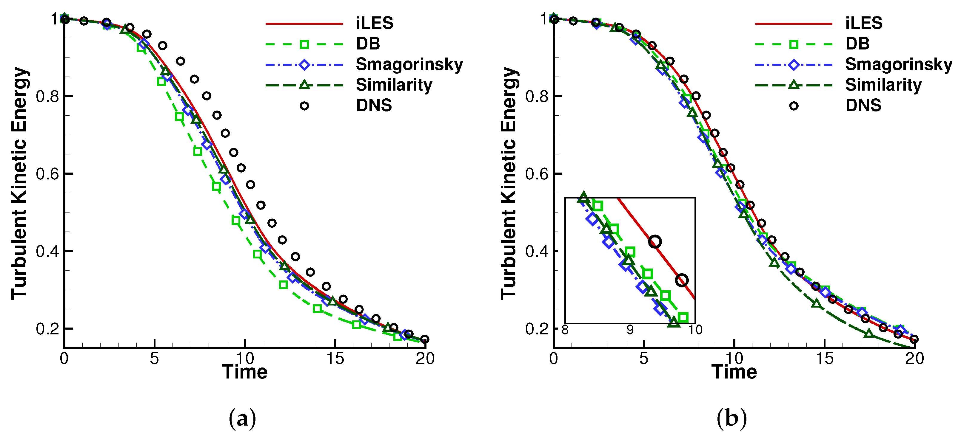
4.2.2. Effects of the Explicit SGS Models and the DB Model

In this simulation, the total dissipation after t / τ = 1 is dominated by the solenoidal dissipation ϵ s and the modeling dissipation ϵ s g s or ϵ a if any model is applied because the residual dissipation ϵ r e s is small and the pressure dilation dissipation ϵ d vanishes after t / τ = 1 . Figure 10 plots time evolution of the modeling dissipation. The Smagorinsky and the Similarity models produce lower level of dissipation, which seems not significantly affected by the solution order. The DB model is sensitive to the initial fluctuation and its behavior is excessively dissipative at the early stage of the simulation. The reason for this is that ϵ a is sensitive to magnitude of all components of the velocity gradient, shown in Equation (46). The p 1 result present higher ϵ a probably because the larger error of the velocity gradient. Though the duration of the initial fluctuation is short, the excessive dissipation of the DB model last until t / τ = 1 , resulting faster drop of the turbulent kinetic energy E k , shown in Figure 7. It can also observed that the excessive ϵ a is damped at higher solution polynomial, as shown in Figure 10. The DB model at p 3 also produces better resolution of ϵ s than p 1 , though still underpredicted. Results of the decaying R e λ shown in Figure 11 shows no evident difference between the simulation methodologies at p 1 , while at p 3 , the DB model produces slightly higher R e λ than the other methodologies at the same order, which indicates that this model may lead to a slightly wider spectra of turbulent scales than the other models. The energy spectrum results at t / τ = 1 shown in Figure 12 again exhibit the excessive dissipation of the DB model at p1 solution polynomial in this test case. It is also observed that at p 3 solution order the excessive dissipation of the DB model is damped. This test case indicates that the DB model may behave more dissipative as compressibility of the flow increases, while in this case the given initial conditions have a strong effect on the dissipation features.

4.3. Compressible Taylor-Green Vortex

In this section, for a further assessment of the DB method in solving compressible problems, the TGV problem is extended to Mach number 1.25, while the other parameters of simulation follow those in Section 4.1. DNS results on 512 2 meshes [42] is taken as reference. Note that in the reference work, the Ducros sensor [60] is applied for adaptive dissipation control of the scheme. Therefore a combination of the DB method and the Ducros sensor, referred to as DBs, is applied in this testcase for a relatively fair comparison, which takes the following form:
μ β , D B s = s D · c β | · u ˜ | ( h / P ) 2 ,
where s D is defined by
s D = H ( ( · u ˜ ) ) ( · u ˜ ) 2 ( · u ˜ ) 2 + w ˜ · w ˜ + ϵ ,
where H is the Heaviside function, w ˜ is the resolved vorticity vector, ϵ = 10 32 is a small constant to avoid zero in denominator. Note that s D = 1 leads to the original DB method defined by Equation (28).
Figure 13a displays the time evolution of the turbulent kinetic energy E k of the compressible Taylor-Green vortex simulated by the original DB method (marked as DB) and the Ducros-sensor-involved DB method (marked as DBs). A different feature of the compressible Taylor-Green vortex problem from its incompressible counterpart is that the turbulent kinetic energy does not decrease from the initial moment but increases slightly before t = 4 when internal energy is converted into kinetic energy. The increase in kinetic energy at the early stage can be observed for DBs method, while the kinetic energy predicted by the original DB method exhibits no significant change at the same time period. Both methods generally agree well with the reference, while the DBs produces more satisfying results because the further reduced dissipation.
Figure 13b plots the total viscous dissipation rate, which follows the definition in reference [42] by ϵ c + ϵ s . It can be observed that the DB method recovers the peak value of the total viscous dissipation rate well when working with the Ducros sensor. Figure 13c plots the sum of total viscous dissipation rate and the extra dissipation brought by the artificial viscous terms, namely, ϵ c + ϵ s + ϵ a to show influence of the DB models on the dissipative process. While in incompressible TGV simulation the DB model at p 3 provides reasonable compensation when the flow becomes under-resolved, as plotted in Figure 5b, in this compressible case, however, the DB models behave over dissipative at the early stage of the flow. It can be observed that the Ducros sensor helps control the over dissipation.
Figure 14, Figure 15 and Figure 16 plot contours of dilatation rate · u , the artificial viscosity μ a v defined by Equation (30) and local Mach number respectively on surfaces of the computational domain via DB and DBs methods at t = 2 . Taking previous study [42] as reference, multiple shock waves are well captured despite the lower resolution than reference. The profiles of shockwaves by DB and DBs methods are similar since that the DBs method mainly reduces artificial viscosity in smooth regions, as shown in Figure 15. Figure 17a shows the line profiles on center line of the computational domain defined by y , z = π at t = 2.5 . It can be observed that both DB models are capable of capturing the shockwave, which is represented by the sudden drop of Mach number. Time evolution of the max Mach number in the computational domain is plotted in Figure 17b. In spite of the early stage before t = 4 , two major peaks of the max Mach number is observed at about t = 6 and t = 9 , respectively. The peak values are more or less smoothed by the original DB method and are recovered well when the Ducros sensor is applied.

4.4. Compressible Channel Flow

In this section, the compressible turbulent channel flow [61] is considered. The channel flow is a canonical configuration for wall-bounded turbulence which consists of simple boundary conditions and geometry. In this paper, we consider the computation of the turbulent channel flow at R e b = 15,334 and M b = 1.5 , where M b and R e b stand for the bulk Mach number and bulk Reynolds number, respectively, defined by
R e b = 2 ρ b u b h / μ w
M b = u b / c w
where h is half-height of the channel, and
ρ b = 1 V V ρ d V
u b = 1 ρ b V V ρ u d V
are the bulk density and bulk velocity in the channel, respectively. μ w and c w are the dynamic viscosity and speed of sound at the wall temperature, respectively. The simulation is carried out in a rectangular box whose size is 2 π h × 2 h × π h in the x, y, z directions. Periodicity conditions are set in streamwise (x) and spanwise (z) directions and isothermal and no-slip walls are set at y = ± h . The initial field for this testcase consists a laminar velocity profile, which is perturbed in spanwise direction. The flow is developed statistically stationary by a uniform pressure gradient, which ensures that the mass flux remains nearly constant. The detailed procedure follows that reported in [19]. The detail of spatial resolutions is given in Table 2, where the Δ + values are estimated as element size divided by the number of solution points per direction. Note that the grid spacing y 1 + is controlled by the distance of first solution point from the wall, which is set in order to capture the small structures developing in the near-wall regions [62], as suggested by some rules-of-thumb for wall-resolving LES [20]. The friction Reynolds number is defined as R e τ = h / δ ν , with δ ν = ν w / u τ being the viscous length scale, ν the kinetic viscosity and u τ the friction velocity. In this study, the R e τ computed from wall stress and average density near the wall is 404, which is lower than the target R e τ = 500 reported by [61]. This gap is resulted from the insufficient resolution [17], which is not as fine as DNS which produce the target value.
Figure 18 shows the mean velocity profile simulated by LES using p 3 FR-DG method with the original DB artificial viscosity. DNS results in [61] are taken as reference. These quantities are presented in semi-local coordinates [63]. It can be observed in Figure 18 that the viscous sublayer is well resolved compared with the DNS result. The resolved buffer layer (about 10 < y + < 40 ) deviates from DNS results, indicating that the turbulent transport is damped in this near-wall region. The bias prediction of the buffer layer leads to the mismatch of the log layer (about y + > 40 ) to DNS results, while the logarithmic dependence is well predicted. We note that in semi-local coordinates the near-wall velocity is used for non-dimensionalization, which is computed from the wall friction in the simulation. As addressed before, the wall stress is underestimated taken the DNS results as reference. This underestimation also partly contributes to the bias of the log layer, and the bulk velocity u b may be a more proper choice for non-dimensionalization for a fair comparison, as reported in [17], which is however not available for this test case. Figure 19 show the Reynolds stresses. A general agreement of trends can be observed. The peaks of the streamwise (Figure 19a) and spanwise (Figure 19c) velocity variances are obvious larger by DB than DNS, the Reynolds shear stress (Figure 19d) is lower by DB, while the wall-normal velocity variances (Figure 19b) of DB agree well with DNS. This is related to the mesh resolution. Note that in Figure 19b the Reynolds stress is better resolved, on whose direction the mesh is relatively finer. To conclude, this testcase indicates the ability of the DB method working with high order FR-DG method to simulate compressible wall-bounded turbulence robustly, and its potential to provide reasonable prediction in this complex flow configuration.

5. Conclusions

In this paper, the ability of the DB artificial viscosity model to simulate under-resolved compressible turbulent flows is investigated in high order flux reconstruction framework. The results are compared with several explicit SGS models and iLES. A detailed derivation of the dissipation rate due to modeling terms, including the Laplacian artificial viscosity model or the explicit SGS model, is conducted. The total dissipation rate of kinetic energy ϵ t o t a l is thus decomposed into several components which are discussed in detail. The effects of the order of solution polynomial, the SGS models and the DB model on the dissipative property and resolving ability in the simulation are investigated thoroughly. The Taylor-Green vortex (TGV) problem at R e = 1600 and freely decaying homogeneous isotropic turbulence (HIT) at M a t 0 = 0.5 are simulated at 120 DOFs with two sets of meshes and solution polynomial orders: a coarse mesh of 30 3 elements with p 3 solution polynomial and a finer mesh of 60 3 elements with p 1 solution polynomial. The DB method is further validated in two compressible problems, the compressible TGV problem and the compressible channel flow problem, with p 3 solution polynomial and relatively coarse meshes.
The results of TGV simulations show that the fourth-order-accurate p 3 FR method matches the reference solution better than the p 1 counterpart at the same low DOFs. The p 1 method is limited by its excessive dissipation and low resolution at small scales and leads to over dissipation at high resolvable wavenumbers. Higher order representation of the solution are superior at resolving energy of the small scales. The explicit SGS models and the DB artificial viscosity model all benefit from more accurate resolution of velocity gradients produced by higher order of solution polynomial. Another benefit brought by the higher order scheme is a general improvement in model dissipation. The dissipation introduced by the DB model at p 3 behaves in a similar manner to some explicit SGS models, and compensates the dissipation when the smallest scales emerge, while the iLES alone is incapable of producing sufficient dissipation. However, it should be noticed that the DB model is sensitive to the dilation term and brings excessive dissipation at p 1 solution polynomial as the error of dilation term is larger.
The HIT simulations show that the initial oscillation of flow field leads to excessive dissipation of DB model, which can be damped at higher solution polynomial order. The initial field also leads to oscillation of the pressure dilation dissipation, which is unaffected by the order of solution polynomial order or simulation methodologies. After the oscillation, lower order solution causes larger error of the pressure dilation dissipation, which leads to over dissipation of the DB model. This also explains the damped dissipation of the DB model at higher solution polynomial order. Dissipation of the Smagorinsky model and the Similarity model are not as sensitive to the solution order as the DB model. The results of spectrum and R e λ indicate that at p 1 solution order the numerical dissipation is excessive regardless of the models applied, and the viscosity dominates on a larger range of scales. The p 3 simulations produce more accurate results on the whole thanks to the lower numerical dissipation and better resolution on small scales. However, future works still need to be conducted on detailed DNS results of the components of ϵ t o t a l derived by this paper.
Both above test cases show that the iLES results via the fourth-order accurate FR method generally match the reference solution well at the given under-resolved DOFs, but they are insufficiently dissipative when the smallest scales emerge in the flow. The explicit SGS models and the DB model all bring additional dissipation to the computation but behave in a different manner. It should be noted that the accuracy of gradient solving is essential to the DB model when the flow is under-resolved. The dissipation of the DB model is excessive at p 1 but grows reasonable at p 3 solution order in smooth regions, which is a suitable property for high order method computation with shocks.
As for the stronger compressible test cases, the compressible TGV problem shows that the DB method is capable of capturing shockwaves accurately in the under-resolved turbulent flow in spite of the insufficient resolution. A simply utilized Ducros sensor is able to control the dissipation of the DB method without sacrificing robustness. The results from compressible channel flow demonstrate the potential of the DB method on simulation of compressible wall-bounded turbulence, while further investigation should be concentrated on the dissipation in the near-wall region and non-dimensionalization based on bulk velocity may be conducted to provide more fair comparison.
In this work, the DB model generally shows good potential for compressible LES using high order method while further investigation should be focused on dissipation features while dealing with wall-bounded turbulence. We also note that further investigation should be conducted at higher than p 3 polynomial order and DNS study which helps provide the components of ϵ t o t a l may be called for as reference. Development of the DB method for more complex flow figures should also be conducted.

Author Contributions

Conceptualization, C.Y. and J.Y.; formal analysis, L.M.; investigation, L.M. and J.Y.; resources, C.Y.; writing—original draft preparation, L.M.; writing—review and editing, L.M. and J.Y.; visualization, L.M.; supervision, C.Y. All authors have read and agreed to the published version of the manuscript.

Funding

This research was funded by the National Natural Science Foundation of China grant number No. 11972064 and No. 11721202.

Data Availability Statement

The data presented in this study are available on request from the corresponding author.

Conflicts of Interest

The authors declare no conflict of interest.

Abbreviations

The following abbreviations are used in this manuscript:
CFDcomputational fluid dynamics
LESlarge eddy simulation
RANSReynolds Averaged Navier-Stokes
DNSDirect Numerical Simulation
FVMfinite volume method
DGdiscontinuous Galerkin
SDspectral difference
FRflux reconstruction
CPRcorrection procedure via reconstruction
DOFsdegrees of freedom
DPWDOFs per wave
ESFRenergy-stable flux reconstruction
TVBtotal variation bounded
WENOweighted essentially non-oscillatory
DBdilation-based
SGSsubgrid scale
TGVTaylor-Green vortex
HIThomogeneous isotropic turbulence
iLESimplicit large eddy simulation
SPssolution points
SSPRK54strong stability preserving five-stage fourth-order Runge-Kutta

References

  1. Slotnick, J.P.; Khodadoust, A.; Alonso, J.; Darmofal, D.; Gropp, W.; Lurie, E.; Mavriplis, D.J. CFD Vision 2030 Study: A Path to Revolutionary Computational Aerosciences; Technical Report; NASA: Washington, DC, USA, 2013. [Google Scholar]
  2. Paliath, U.; Premasuthan, S. Large eddy simulation for jet installation effects. In Proceedings of the 19th AIAA/CEAS Aeroacoustics Conference, Berlin, Germany, 27–29 May 2013; p. 2137. [Google Scholar]
  3. Wei, X.; Zhang, M.; An, Z.; Wang, J.; Huang, Z.; Tan, H. Large eddy simulation on flame topologies and the blow-off characteristics of ammonia/air flame in a model gas turbine combustor. Fuel 2021, 298, 120846. [Google Scholar] [CrossRef]
  4. Asada, K.; Kawai, S. Large-eddy simulation of airfoil flow near stall condition at Reynolds number 2.1 ×10⁶. Phys. Fluids 2018, 30, 085103. [Google Scholar] [CrossRef]
  5. Garnier, E.; Adams, N.; Sagaut, P. Large Eddy Simulation for Compressible Flows; Springer Science & Business Media: Berlin/Heidelberg, Germany, 2009. [Google Scholar]
  6. Vermeire, B.C.; Nadarajah, S.; Tucker, P.G. Implicit large eddy simulation using the high-order correction procedure via reconstruction scheme. Int. J. Numer. Methods Fluids 2016, 82, 231–260. [Google Scholar] [CrossRef]
  7. Garnier, E.; Mossi, M.; Sagaut, P.; Comte, P.; Deville, M.O. On the Use of Shock-Capturing Schemes for Large-Eddy Simulation. J. Comput. Phys. 1999, 153, 273–311. [Google Scholar] [CrossRef]
  8. Wang, Z.; Li, Y.; Jia, F.; Laskowski, G.; Kopriva, J.; Paliath, U.; Bhaskaran, R. Towards industrial large eddy simulation using the FR/CPR method. Comput. Fluids 2017, 156, 579–589. [Google Scholar] [CrossRef]
  9. Cockburn, B.; Karniadakis, G.E.; Shu, C.W. Discontinuous Galerkin Methods: Theory, Computation and Applications; Springer Science & Business Media: Berlin/Heidelberg, Germany, 2012; Volume 11. [Google Scholar]
  10. Liu, Y.; Vinokur, M.; Wang, Z. Spectral difference method for unstructured grids I: Basic formulation. J. Comput. Phys. 2006, 216, 780–801. [Google Scholar] [CrossRef]
  11. Huynh, H.T. A flux reconstruction approach to high-order schemes including discontinuous Galerkin methods. In Proceedings of the Collection of Technical Papers—18th AIAA Computational Fluid Dynamics Conference, Miami, FL, USA, 25–28 June 2007; Volume 1, pp. 698–739. [Google Scholar] [CrossRef]
  12. Haga, T.; Gao, H.; Wang, Z.J. A High-Order Unifying Discontinuous Formulation for the Navier-Stokes Equations on 3D Mixed Grids. Math. Model. Nat. Phenom. 2011, 6, 28–56. [Google Scholar] [CrossRef] [Green Version]
  13. Lodato, G.; Castonguay, P.; Jameson, A. Structural Wall-modeled LES Using a High-order Spectral Difference Scheme for Unstructured Meshes. Flow Turbul. Combust. 2014, 92, 579–606. [Google Scholar] [CrossRef]
  14. Yi, L.U.; Kai, L.; Dawes, W.N. Flow simulation system based on high order space-time extension of flux reconstruction method. In Proceedings of the 53rd AIAA Aerospace Sciences Meeting, Kissimmee, FL, USA, 5–9 January 2015. [Google Scholar]
  15. Uranga, A.; Persson, P.O.; Drela, M.; Peraire, J. Implicit Large Eddy Simulation of transition to turbulence at low Reynolds numbers using a Discontinuous Galerkin method. Int. J. Numer. Methods Eng. 2011, 87, 232–261. [Google Scholar] [CrossRef]
  16. Vermeire, B.; Witherden, F.; Vincent, P. On the utility of GPU accelerated high-order methods for unsteady flow simulations: A comparison with industry-standard tools. J. Comput. Phys. 2017, 334, 497–521. [Google Scholar] [CrossRef]
  17. Fernandez, P.; Nguyen, N.C.; Peraire, J. On the ability of discontinuous Galerkin methods to simulate under-resolved turbulent flows. arXiv 2018, arXiv:1810.09435. [Google Scholar]
  18. Witherden, F.D.; Vermeire, B.C.; Vincent, P.E. Heterogeneous Computing on Mixed Unstructured Grids with PyFR. Comput. Fluids 2014, 120, 173–186. [Google Scholar] [CrossRef] [Green Version]
  19. Lodato, G.; Castonguay, P.; Jameson, A. Discrete filter operators for large-eddy simulation using high-order spectral difference methods. Int. J. Numer. Methods Fluids 2013, 72, 231–258. [Google Scholar] [CrossRef]
  20. Blackburn, H.M.; Schmidt, S. Spectral element filtering techniques for large eddy simulation with dynamic estimation. J. Comput. Phys. 2003, 186, 610–629. [Google Scholar] [CrossRef] [Green Version]
  21. Vincent, P.E.; Castonguay, P.; Jameson, A. A new class of high-order energy stable flux reconstruction schemes. J. Sci. Comput. 2011, 47, 50–72. [Google Scholar] [CrossRef]
  22. Castonguay, P.; Williams, D.M.; Vincent, P.E.; Jameson, A. Energy stable flux reconstruction schemes for advection–diffusion problems. Comput. Methods Appl. Mech. Eng. 2013, 267, 400–417. [Google Scholar] [CrossRef]
  23. Williams, D.M.; Castonguay, P.; Vincent, P.E.; Jameson, A. Energy stable flux reconstruction schemes for advection–diffusion problems on triangles. J. Comput. Phys. 2013, 250, 53–76. [Google Scholar] [CrossRef]
  24. Williams, D.; Jameson, A. Energy stable flux reconstruction schemes for advection–diffusion problems on tetrahedra. J. Sci. Comput. 2014, 59, 721–759. [Google Scholar] [CrossRef]
  25. Wang, Z.J.; Fidkowski, K.; Abgrall, R.; Bassi, F.; Caraeni, D.; Cary, A.; Deconinck, H.; Hartmann, R.; Hillewaert, K.; Huynh, H.T.; et al. High-order CFD methods: Current status and perspective. Int. J. Numer. Methods Fluids 2013, 72, 811–845. [Google Scholar] [CrossRef]
  26. Vermeire, B.; Cagnone, J.S.; Nadarajah, S. ILES using the correction procedure via reconstruction scheme. In Proceedings of the 51st AIAA Aerospace Sciences Meeting Including the New Horizons Forum and Aerospace Exposition, Grapevine, TX, USA, 7–10 January 2013; p. 1001. [Google Scholar]
  27. Lodato, G.; Chapelier, J.B. Evaluation of the spectral element dynamic model for large-eddy simulation on unstructured, deformed meshes. Flow Turbul. Combust. 2018, 101, 271–294. [Google Scholar] [CrossRef]
  28. Wang, Z.; Zhang, L.; Liu, Y. Spectral (finite) volume method for conservation laws on unstructured grids IV: Extension to two-dimensional systems. J. Comput. Phys. 2004, 194, 716–741. [Google Scholar] [CrossRef]
  29. Shu, C.W. TVB uniformly high-order schemes for conservation laws. Math. Comput. 1987, 49, 105–121. [Google Scholar] [CrossRef]
  30. Biswas, R.; Devine, K.D.; Flaherty, J.E. Parallel, adaptive finite element methods for conservation laws. Appl. Numer. Math. 1994, 14, 255–283. [Google Scholar] [CrossRef]
  31. Burbeau, A.; Sagaut, P.; Bruneau, C.H. A problem-independent limiter for high-order RungeKutta discontinuous Galerkin methods. J. Comput. Phys. 2001, 169, 111–150. [Google Scholar] [CrossRef]
  32. Krivodonova, L. Limiters for high-order discontinuous Galerkin methods. J. Comput. Phys. 2007, 226, 879–896. [Google Scholar] [CrossRef]
  33. Qiu, J.; Shu, C.W. Runge–Kutta Discontinuous Galerkin Method Using WENO Limiters. SIAM J. Sci. Comput. 2005, 26, 907–929. [Google Scholar] [CrossRef]
  34. Luo, H.; Baum, J.D.; Lohner, R. A Hermite WENO-based limiter for discontinuous galerkin method on unstructured grids. In Proceedings of the 45th AIAA Aerospace Sciences Meeting, Reno, NV, USA, 8–11 January 2007. [Google Scholar]
  35. Cook, A.W.; Cabot, W.H. Hyperviscosity for shock-turbulence interactions. J. Comput. Phys. 2005, 203, 379–385. [Google Scholar] [CrossRef]
  36. Mani, A.; Larsson, J.; Moin, P. Suitability of artificial bulk viscosity for large-eddy simulation of turbulent flows with shocks. J. Comput. Phys. 2009, 228, 7368–7374. [Google Scholar] [CrossRef]
  37. Yu, J.; Hesthaven, J.S. A study of several artificial viscosity models within the discontinuous galerkin framework. Commun. Comput. Phys. 2020, 27, 1309–1343. [Google Scholar]
  38. Blaisdell, G.A. Review of “Implicit Large Eddy Simulation: Computing Turbulent Fluid Dynamics”. AIAA J. 2008, 46, 3168–3170. [Google Scholar] [CrossRef]
  39. Fernandez, P.; Nguyen, N.C.; Peraire, J. A physics-based shock capturing method for large-eddy simulation. arXiv 2018, arXiv:1806.06449. [Google Scholar]
  40. Kawai, S.; Shankar, S.K.; Lele, S.K. Assessment of localized artificial diffusivity scheme for large-eddy simulation of compressible turbulent flows. J. Comput. Phys. 2010, 229, 1739–1762. [Google Scholar] [CrossRef]
  41. Ansorge, R.; Bijl, H.; Meister, A.; Sonar, T. Recent Developments in the Numerics of Nonlinear Hyperbolic Conservation Laws: Lectures Presented at a Workshop at the Mathematical Research Institute, Oberwolfach, Germany, 15–21 January 2012; Springer Science & Business Media: Berlin/Heidelberg, Germany, 2012; Volume 120. [Google Scholar]
  42. Lusher, D.J.; Sandham, N.D. Assessment of low-dissipative shock-capturing schemes for the compressible Taylor–Green vortex. AIAA J. 2021, 59, 533–545. [Google Scholar] [CrossRef]
  43. Blazek, J. Computational Fluid Dynamics: Principles and Applications; Butterworth-Heinemann: Oxford, UK, 2015. [Google Scholar]
  44. Lodato, G.; Vervisch, L.; Domingo, P. A compressible wall-adapting similarity mixed model for large-eddy simulation of the impinging round jet. Phys. Fluids 2009, 21, 35102. [Google Scholar] [CrossRef]
  45. Roe, P. Efficient construction and utilization of approximate Riemann solutions. Comput. Methods Appl. Sci. Eng. 1984, 6, 499–518. [Google Scholar]
  46. Peraire, J.; Persson, P.O. The compact discontinuous galerkin (CDG) method for elliptic problems. SIAM J. Sci. Comput. 2007, 30, 1806–1824. [Google Scholar] [CrossRef] [Green Version]
  47. Gottlieb, S. On high order strong stability preserving Runge-Kutta and multi step time discretizations. J. Sci. Comput. 2005, 25, 105–128. [Google Scholar] [CrossRef] [Green Version]
  48. Smagorinsky, J.S. General Circulation Experiments with the Primitive Equations. Mon. Weather. Rev. 1963, 91, 99–164. [Google Scholar] [CrossRef]
  49. Bardina, J.; Ferziger, J.; Reynolds, W. Improved subgrid-scale models for large-eddy simulation. In Proceedings of the 13th Fluid and Plasmadynamics Conference, Snowmass, CO, USA, 14–16 July 1980; p. 1357. [Google Scholar]
  50. Carton de Wiart, C.; Hillewaert, K.; Duponcheel, M.; Winckelmans, G. Assessment of a discontinuous Galerkin method for the simulation of vortical flows at high Reynolds number. Int. J. Numer. Methods Fluids 2014, 74, 469–493. [Google Scholar] [CrossRef]
  51. Samtaney, R.; Pullin, D.I.; Kosović, B. Direct numerical simulation of decaying compressible turbulence and shocklet statistics. Phys. Fluids 2001, 13, 1415–1430. [Google Scholar] [CrossRef] [Green Version]
  52. Taylor, G.I.; Green, A.E. Mechanism of the production of small eddies from large ones. Proc. R. Soc. Lond. Ser. A Math. Phys. Sci. 1937, 158, 499–521. [Google Scholar] [CrossRef] [Green Version]
  53. Debonis, J.R. Solutions of the Taylor-Green vortex problem using high-resolution explicit finite difference methods. In Proceedings of the 51st AIAA Aerospace Sciences Meeting including the New Horizons Forum and Aerospace Exposition, Grapevine, TX, USA, 7–10 January 2013. [Google Scholar]
  54. Bogey, C.; Bailly, C. A family of low dispersive and low dissipative explicit schemes for flow and noise computations. J. Comput. Phys. 2004, 194, 194–214. [Google Scholar] [CrossRef]
  55. Shu, C.W.; Don, W.S.; Gottlieb, D.; Schilling, O.; Jameson, L. Numerical convergence study of nearly incompressible, inviscid Taylor–Green vortex flow. J. Sci. Comput. 2005, 24, 1–27. [Google Scholar] [CrossRef]
  56. Bull, J.R.; Jameson, A. Simulation of the Taylor–Green vortex using high-order flux reconstruction schemes. AIAA J. 2015, 53, 2750–2761. [Google Scholar] [CrossRef] [Green Version]
  57. Rogallo, R.S. Numerical Experiments in Homogeneous Turbulence; National Aeronautics and Space Administration: Washington, DA, USA, 1981; Volume 81315. [Google Scholar]
  58. Ristorcelli, J.R.; Blaisdell, G.A. Consistent initial conditions for the DNS of compressible turbulence. Phys. Fluids 1997, 9, 4–6. [Google Scholar] [CrossRef] [Green Version]
  59. Movahed, P.; Johnsen, E. The mixing region in freely decaying variable-density turbulence. J. Fluid Mech. 2015, 772, 386–426. [Google Scholar] [CrossRef]
  60. Ducros, F.; Ferrand, V.; Nicoud, F.; Weber, C.; Darracq, D.; Gacherieu, C.; Poinsot, T. Large-eddy simulation of the shock/turbulence interaction. J. Comput. Phys. 1999, 152, 517–549. [Google Scholar] [CrossRef]
  61. Modesti, D.; Pirozzoli, S. Reynolds and Mach number effects in compressible turbulent channel flow. Int. J. Heat Fluid Flow 2016, 59, 33–49. [Google Scholar] [CrossRef]
  62. Le Bras, S.; Deniau, H.; Bogey, C.; Daviller, G. Development of compressible large-eddy simulations combining high-order schemes and wall modeling. AIAA J. 2017, 55, 1152–1163. [Google Scholar] [CrossRef] [Green Version]
  63. Huang, P.; Coleman, G.; Bradshaw, P. Compressible turbulent channel flows: DNS results and modelling. J. Fluid Mech. 1995, 305, 185–218. [Google Scholar] [CrossRef]
Figure 1. Time evolution of the total volume-averaged kinetic energy E k of TGV simulation, R e = 1600 , 120 3 DOFs. (a) p 1 ; (b) p 3 .
Applsci 12 12272 g001
Figure 2. Time evolution of the overall dissipation ϵ t o t a l of TGV simulation, R e = 1600 , 120 3 DOFs. (a) p 1 ; (b) p 3 .
Applsci 12 12272 g002
Figure 3. Time evolution of the solenoidal dissipation ϵ s of TGV simulation, R e = 1600 , 120 3 DOFs. (a) p 1 ; (b) p 3 .
Applsci 12 12272 g003
Figure 4. Time evolution of the pressure dilation ϵ d of TGV simulation, R e = 1600 , 120 3 DOFs.
Applsci 12 12272 g004
Figure 5. Time evolution of the additional dissipation ϵ s g s for explicit LES and ϵ a for LES with artificial viscosity of TGV simulation, R e = 1600 , 120 3 DOFs. (a) p 1 ; (b) p 3 .
Applsci 12 12272 g005
Figure 6. Energy spectra of TGV simulation at t = 9 of TGV simulation, R e = 1600 , 120 3 DOFs. (a) p 1 ; (b) p 3 .
Applsci 12 12272 g006
Figure 7. Time evolution of the total volume-averaged kinetic energy E k of HIT simulation, M a t 0 = 0.5 , 120 3 DOFs. (a) p 1 ; (b) p 3 .
Applsci 12 12272 g007
Figure 8. Time evolution of the overall dissipation ϵ t o t a l of HIT simulation, M a t 0 = 0.5 , 120 3 DOFs. (a) p 1 ; (b) p 3 .
Applsci 12 12272 g008
Figure 9. Time evolution of the solenoidal dissipation ϵ s of HIT simulation, M a t 0 = 0.5 , 120 3 DOFs. (a) p 1 ; (b) p 3 .
Applsci 12 12272 g009
Figure 10. Time evolution of the dissipation ϵ s g s for explicit LES and ϵ a for LES with artificial viscosity of HIT simulation, M a t 0 = 0.5 , 120 3 DOFs. (a) p 1 ; (b) p 3 .
Applsci 12 12272 g010
Figure 11. Time evolution of R e λ of HIT simulation, M a t 0 = 0.5 , 120 3 DOFs. (a) p 1 ; (b) p 3 .
Applsci 12 12272 g011
Figure 12. Energy spectra at t/ τ = 1 of HIT simulation, M a t 0 = 0.5 , 120 3 DOFs. (a) p 1 ; (b) p 3 .
Applsci 12 12272 g012
Figure 13. Time evolution of (a) turbulent kinetic energy and (b) dissipation of compressible TGV simulation, M a = 1.25 , R e = 1600 , 120 3 DOFs, p3. (a) turbulent kinetic energy; (b) ϵ c + ϵ s ; (c) ϵ c + ϵ s + ϵ a .
Applsci 12 12272 g013
Figure 14. Profile of shock waves at t = 2 by contour of dilatation rate via (a) original DB and (b) DBs of compressible TGV simulation, M a = 1.25 , R e = 1600 , 120 3 DOFs, p3. (a) original DB; (b) DBs.
Applsci 12 12272 g014
Figure 15. Contour of artificial viscosity at t = 2 via (a) original DB and (b) DBs of compressible TGV simulation, M a = 1.25 , R e = 1600 , 120 3 DOFs, p3.
Applsci 12 12272 g015
Figure 16. Profile of shock waves at t = 2 by contour of local Mach number via (a) original DB and (b) DBs of compressible TGV simulation, M a = 1.25 , R e = 1600 , 120 3 DOFs, p3.
Applsci 12 12272 g016
Figure 17. Local Mach number along y , z = π line and time evolution of max Mach number of compressible TGV simulation, M a = 1.25 , R e = 1600 , 120 3 DOFs, p3. (a) local Mach number along y , z = π line; (b) max Mach number.
Applsci 12 12272 g017
Figure 18. Mean velocity profile in supersonic channel flow at M b = 1.5 and R e b = 15,334 based on height of the channel.
Applsci 12 12272 g018
Figure 19. Reynolds stresses in supersonic channel flow at M b = 1.5 and R e b = 15,334 based on height of the channel. (a) u u ; (b) v v ; (c) w w ; (d) u v .
Applsci 12 12272 g019
Table 1. Runtime for 1000 iterations of TGV problem at 120 3 DOFs.
DiscretizationDOFsModelRuntime(s)Ratio
30 3 elements, p 3 120iLES34431.0
DB39351.14
Smagorinsky46311.35
similarity48231.40
60 3 elements, p 1 120iLES36861.07
DB42461.23
Smagorinsky51971.51
similarity52001.51
Table 2. Spatial resolution for channel flow computation.
ComputationDOF Δ x + Δ z + Δ y avg + y 1 +
LES with DB method 120 × 96 × 60 2626100.88
Publisher’s Note: MDPI stays neutral with regard to jurisdictional claims in published maps and institutional affiliations.

