Article

Limiting Conditions for Droplet Fragmentation of Stabilized Suspension Fuels

by
Dmitrii V. Antonov
*,
Daniil S. Romanov
and
Genii V. Kuznetsov
Heat and Mass Transfer Simulation Laboratory, National Research Tomsk Polytechnic University, 30 Lenin Avenue, 634050 Tomsk, Russia
*
Author to whom correspondence should be addressed.
Appl. Sci. 2022, 12(23), 12271; https://doi.org/10.3390/app122312271
Submission received: 13 October 2022 / Revised: 25 November 2022 / Accepted: 29 November 2022 / Published: 30 November 2022
(This article belongs to the Special Issue Fuel Combustion Mechanisms, Characteristics and Emission Analysis)

Abstract

:
The main barrier to the wide use of composite liquid fuels in the energy sector is the significant sedimentation of solid particles during fuel storage and transportation. As a result, the composition of fuel slurries changes quite fast and considerably when yet another portion of fuel is pumped from a storage tank. Stabilizing additives are one of the possible solutions to this problem. The technology of primary and secondary slurry fuel atomization is generally considered promising for obtaining a spray of small fragments (droplets and particles). This way, droplets of liquid components and solid particles can be produced with a size of less than 10 μm. A fuel aerosol with particles and droplets this small burns out rapidly. The most effective secondary droplet atomization technology is based on their microexplosive breakup in combustion chambers by superheating the water in the fuel to exceed its nucleation (boiling) point. As part of this research, we studied the impact of the main stabilizing additives to slurry fuels on droplet breakup behavior: heating time until breakup, breakup delay and duration, and the number, size, and velocities of secondary fragments. Soy lecithin and sodium lignosulfonate were used as stabilizers. The main components of the fuel slurries were water, rapeseed oil, diesel fuel, coal processing waste (filter cake), coking bituminous coal, soy lecithin, and sodium lignosulfonate. Droplets were heated at an ambient gas temperature ranging from 450 to 1050 K until the breakup conditions were achieved. Mathematical expressions were obtained for the relationship between input parameters and the key characteristics of the process. Principal differences and overall patterns of droplet breakup were established for slurries with and without stabilizing additives.

Graphical Abstract

1. Introduction

The problems of coal-dependent energy providers around the world are mostly related to high anthropogenic emissions from the combustion of natural solid fuels [1,2]. A highly potential solution to these problems is based on burning these fuels as part of blends with various additives [3,4]: water, slimes, heavy coal-tar products, resins, biomass, etc. Each of these additives makes it possible to vary the technological, economic, environmental, and energy performance indicators of power plants fired by composite fuels [5,6]. In particular, a multicriteria analysis has shown [7,8] that water-based slurry fuels exceed natural solid fuels in the relative performance parameters. As a result, the so-called composite liquid fuels became widely known [9,10]. These fuels are commonly classified into coal–water slurries with petrochemicals [11] and without petrochemicals [12,13]. These fuel types are highly viscous since they normally contain 30% to 60% of solid particles [14]. Hence, the layer structure of such fuels changes quite significantly during their storage in reservoirs and transportation, and so does the structure of jets and separate droplets formed during atomization. This affects the temperature and concentration fields in the combustion chamber, fuel combustion efficiency, environmental indicators of plant operation, etc.
Composite liquid fuels are notable for solid particle sedimentation and agglomeration in droplets, intensifying the fuel stratification [15,16,17]. Emulsified and slurry fuels are conventionally stabilized with the help of a set of additives, with oils, solvents, soy lecithin, and sodium lignosulfonate being regarded as the most promising ones [16,18]. These stabilizing additives can vary the fuel properties in a controlled manner during storage and transportation. Coal–water slurry fuels generally hold more potential for northern regions with their abundant reserves of natural solid fuels [19]. In this case, the composition of slurry fuels needs to be kept stable at low ambient temperatures, and this is when soy lecithin and sodium lignosulfonate are useful [16,18]. It remains unstudied how the stabilizing additives to slurry fuels affect the droplet breakup behavior upon intense heating (i.e., the so-called secondary atomization directly in the combustion chamber). Such breakup may proceed in several regimes. Emulsified and slurry fuels typically break up in the puffing regime [20,21] when liquid fragments break off from the surface of the parent droplet throughout the entire heating time (and fuel droplets are heated for most of their residence time in a combustion chamber). Droplets with immiscible flammable (e.g., diesel, kerosene, rapeseed oil, etc.) and nonflammable (water) components more often exhibit microexplosion [22,23] to form an aerosol of small fragments within a short heating time. By varying the concentrations of liquid flammable and nonflammable components in droplets, one can change the break-up regimes (from microexplosion to puffing or back), critical conditions (heating times and threshold temperatures), and outcomes (size and number of secondary fragments). It is important to analyze the impact of stabilizing additives to slurry fuels on droplet breakup behavior in a wide range of temperatures. This was the motivation of the present research.
The aim of this research is to experimentally determine the effect of stabilizing additives to promising slurry fuels (that would prolong their homogeneous structure) on droplet evaporation, dehydration, and breakup behavior in the puffing and microexplosion regimes upon intense heating. Current fundamental results of limiting conditions for suspension fuels droplet fragmentation was based on new methods of preparation stabilized CWS and CWSP fuels [24]. New findings presented in this paper are important in atomization of stabilized fuels inside combustion chambers to increase combustion efficiency alternative types of fuels.

2. Materials

Coal–water slurries with (CWSP) and without petrochemicals (CWS) are blends of two to four components. CWSP generally consists of solid and liquid parts, and each of them may contain several combustible and noncombustible components or additives. Table 1 presents the main thermophysical and transport properties of CWS and CWSP components used in the experiments.
Bituminous coking coal (type K) was used as the solid combustible component. The total mass fraction of the solid components in CWS and CWSP was taken as 50 wt.%. Rapeseed oil and diesel fuel with a mass fraction of 1 wt.% were used as liquid combustible components. Distilled water is a typical liquid nonflammable component with a mass fraction of 49–50 wt.%. For the microexplosive breakup to occur, a CWSP must contain both the combustible and the chemically inert component (water). The main stabilizing additives to composite fuels were soy lecithin [16], rapeseed oil (GOST 31759-2012) [18], diesel fuel [17], and sodium lignosulfonate [26] as one of the promising polymer stabilizers. Coal processing waste (type K filter cake) is also considered a promising solid component of fuel slurries. Experiments were also performed with slurries based on the same type of bituminous coal as the filter cake to compare their breakup behavior. Table 2 presents the results obtained from the ultimate and proximate analysis of solid components.
Measurements of the solid fuel properties presented in Table 2 were based on standard analytical instruments and methods. The calorific value of the solid fuels was determined in accordance with ISO standards [27,28]. Ash content and volatiles were determined according to the procedures reported in [29]. The elemental composition of solid fuels was determined using the vario MICRO cube Elementar according to the procedure in [30].
Bituminous coal and filter cake are polydisperse materials containing small particles with an average size of 20–30 μm and large ones with a size of 180–200 μm. The research of breakup behavior required a narrower particle size range, so bituminous coal and filter cake were first dried in a furnace at 105 °C for 2.5 h and then ground in a high-speed rotor mill (Pulverisette 14 with a final fineness ranging from 0.08 to 6 mm and rotor speed from 6000 to 20,000 rpm). To obtain the required particle size, the resulting components were sieved using an ANALYSETTE 3 SPARTAN sieve shaker (sieving time 3–20 min., particle size ranging from 20 to 140 μm). As a result, the particle size did not exceed 90 μm.
Composite fuels were then prepared in the following stages. Water and additives were stirred with an AIBOTE ZNCLBS-2500 magnetic stirrer (stirring time ≈ 10 min, bar rotating speed 1500 rpm). Then the solid components were poured into the container and the slurry was stirred for about 15 min until homogeneous. Bituminous coal and filter cake were poured gradually into the container to avoid agglomeration. The required mass fraction of components was determined using a Vibra AF 225DRCE analytical balance with n increment of 10−6. Table 3 lists the fuel mixtures used in the research.

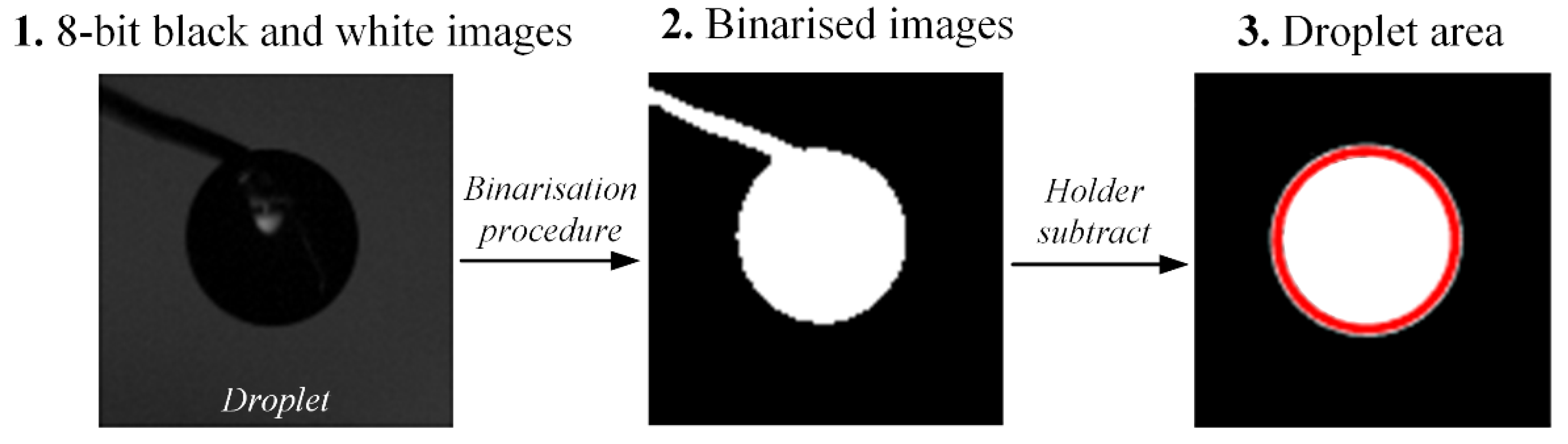
3. Experimental Technique

The intense breakup of slurry fuel droplets can be provided using different heating schemes with the dominating convective [31,32], radiative [33], conductive [34,35], or mixed [36,37] heat exchange. Droplet microexplosion occurs after the longest heating time in a tubular muffle furnace (model reactor or combustion chamber of a power plant) compared to the conductive droplet heating on a substrate [38]. However, the longer the heating time, the more secondary fragments with minimum sizes are produced [39,40]. Previous research has shown [41] that microexplosion and puffing occur in any of the above heating schemes but in certain temperature ranges depending on droplet composition, type, size, and heating rate [42]. The characteristics of secondary fragments can be recorded using high-speed cameras [39,43,44]. The heating scheme affects the velocities and trajectories of secondary fragments and, hence, the accuracy of recording their main characteristics (number, size, velocity, trajectory, momentum, component composition, etc.). An alcohol burner flame was used as the heating scheme for slurry fuels in this study. The analysis of the findings in Ref. [33] shows that parent droplets should be heated in flames to provide the most accurate monitoring of the number, size, velocity, component composition, and energy of secondary fragments. When heated in flames, parent droplets break up into the greatest number of secondary fragments compared to droplet heating in a muffle furnace, on a substrate, or in a heated air flow [33]. That is why this was the scheme of choice for the present research (Figure 1). The burner flame heating scheme simulates the wildfire conditions and combustion chamber conditions where radiant heat exchange prevails.
The high-temperature flame zone was created with the help of a burner based on ethanol (maximum temperature: 1150 K) (Figure 1). The temperature in the flame of the alcohol burner was recorded using a system featuring a National Instruments data collection module and fast thermocouples with a measurement accuracy of at least ±3 K and a response time of less than 0.1 s. To calibrate the system, the flame temperature was measured in several sections at different distances with an increment of 0.5 cm from the burner. The temperature measurement scheme and data are given in Figure 1b.
The droplets were introduced into the test zone using a positioning mechanism with a holder—a nichrome wire, 0.2 mm in diameter. The test zone was lit using a MultiLed QT lamp head to improve the image contrast of the parent and child droplets. The lamp head had the following parameters: 15° lens; 12,000 Lumen (white), 150 W. Light intensity (0–100%) was controlled by a MultiLed G8 controller. The droplet heating, evaporation, and breakup were recorded using a slow-motion video camera (Phantom Miro M310). The frame rate was set at 1000 pps (512 × 512 pix resolution). The resulting footage was processed in the Phantom Camera Control software. During processing, we recorded the delay of slurry fuel droplet breakup, total drying times of slurry fuels, parent droplet size, along with the number, sizes, and velocities of secondary fragments. The systematic errors in the measurement of the above characteristics did not exceed 0.002 s for times, 0.025 mm for sizes, and 0.05 m/s for velocities. The size of droplets was measured when they reached the heating zone. The droplet diameter was measured in two sections, and then the average droplet diameter was written as D = (D1 + D2)/2 and the radius as Rd = D/2.
The number (Ncd) and size (rcd) of secondary droplets were determined using an in-house software code written in Mathematica (for more details, see Ref. [45]). We explored the footage of the experiments, looking for the patterns of droplet breakup into secondary fragments. The frames of interest were imported into Mathematica in tiff format. The two-liquid droplet breakup outcomes were analyzed using an application that searched for the binarization threshold, and then the main engine identified the elements and calculated their number and size with respect to the scale factor. Each part involved background subtraction. Secondary fragments were highlighted using the key functions of the main engine: Morphological Binarize and Median filter. To calculate their number and sizes, each highlighted object was represented in the form of a spherical droplet of the same dimensions as the highlighted object. The size of secondary droplets was determined with an accuracy of at least ±4%.

4. Results and Discussion

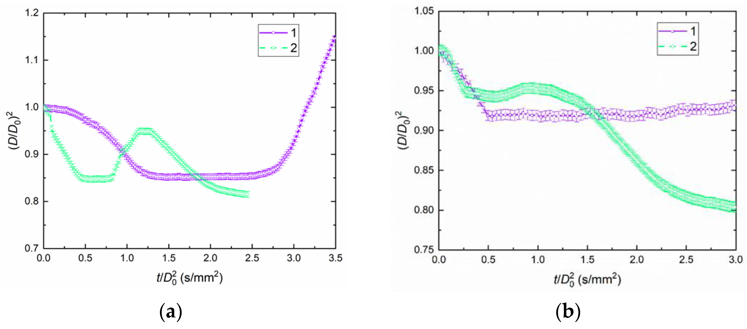
4.1. Droplet Behaviors

We used the following terms for the analysis of the research findings: droplet swelling, drying, destruction, and intact state. By droplet swelling we mean an increase in the droplet size due to lower effective density of the fuel composition and higher vapor pressure. Drying is the release of volatile components from the porous structure of fuel blends. Destruction occurs when fragments break off from the parent droplet due to higher vapor pressure in the porous structure of fuel blends. Intact state means no significant changes in the droplet shape and no fragments breaking off upon heating. Figure 2 presents typical snapshots showing the patterns of liquid film evaporation, near-surface layer dehydration, and fragmentation of C50W49D1 (a), C50W49LE1 (b), C50W49LI1 (c), C50W49R1 (d), and C50W50 (e) blends at Ta ≈ 450 K and Rd0 ≈ 1.0 mm. Droplets of fuel blends with different effective viscosities had different shapes on the same holder. When droplets of these fuels are injected using various atomizers, their shapes follow the same patterns: droplets take an ellipsoidal, spherical, disk shape, etc. At the same time, earlier experiments [46,47,48] have shown that the shape of a moving droplet transforms continuously, though more slowly with an increase in the liquid viscosity. Note that the shape of CWS and CWSP fuels is not always spherical even in practical applications because it contains a high concentration (more than 50%) of solid particles. Typical videoframes of droplet breakup in puffing and microexplosion modes are shown in Supplementary Materials A.
The experiments showed two breakup regimes occurring for different physical reasons. In particular, droplets of the compositions without flammable liquids broke up after they were dehydrated and their porous structure was filled with water vapor. Afterward, due to an increase in the water vapor pressure, some of the fuel broke off from the droplet surface. If a blend contained a flammable liquid, the vapor bubble nucleation was intensified at the interface between water and liquid combustible component. Droplets were heated more rapidly if they contained solid particles. The latter also served as vaporization centers upon intense heating. The videos obtained using high-speed recordings do not make it possible to observe bubble nucleation near the liquid/liquid interface or around solid particles. In the near-surface layers, however, these effects were observed quite consistently. The slurry droplet surface tended to dry somewhat, followed by local vapor bubble nucleation and implosion, which, in turn, was followed by puffing of liquid and solid particles. The larger the droplet volume was, the more the droplet surface deformed with consecutive solid particle surface drying in the near-surface layer, vapor bubble nucleation and growth, droplet swelling, bubble implosion, separation of liquid fragments, entrainment of small solid particles, and large agglomerates breaking off when the dehydrated remnants of the composite droplet broke up. The analysis of physical patterns in the processes under study has shown that solid particles accelerate droplet heating due to an increase in the thermal conductivity and diffusivity. Faster heat exchange, however, does not give enough time for cascade bubble nucleation and growth inside the droplet and at its surface. A liquid film rapidly evaporates from the droplet surface, and the particle surface dries. It is important to keep a certain balance between the thermal processes and mass exchange processes to intensify the vaporization and boiling in a heterogeneous droplet. Note that child droplets initially break up due to relatively high velocity splash toward the upstream part. Then, child droplets fall freely by gravity force. Typical video-frames of droplet breakup with different coal particle concentrations are shown in Supplementary Materials B.
The comparative analysis of the footage from the CWS and CWSP experiments indicates significant differences between droplet breakup regimes with each of the added components. At the same time, the temperature range of consistent breakup differed significantly for droplets of different component composition. The greater the concentration of solid particles in a droplet, the faster it reached the breakup temperature. The required temperature was lower, but the breakup was quite weak. Large agglomerates were the most frequent outcome. Two-liquid droplets without solid particles typically broke up in the puffing and microexplosion regime to form a large number of small liquid fragments. The longer it took for a droplet to reach the breakup temperature, the more secondary fragments were formed in the process. A high proportion of water in such initial droplets led to a transition from microexplosion to puffing. Three-component droplets (for instance, based on water, coal, and oil) also broke up in two regimes: puffing and microexplosion. The component concentration played a fundamental role in the regime transition. In particular, the microexplosion could be intensified by increasing the concentration of the liquid combustible component and minimizing the proportion of solid particles and water in a fuel slurry.
The breakup regimes of composite liquid fuel droplets containing solid particles were found to depend greatly on the surface properties of those solid particles. For instance, we compared the heating and breakup behaviors of composite droplets based on coal and filter cake. Under identical heating conditions, droplets with coal particles broke up more intensely than composite fuels based on filter cake. This effect was observed throughout the temperature range under study. It can be attributed to the significantly different surface properties of the filter cake and coal. Filter cake particles were more hydrophilic. Liquid penetrated the pores between particles and was retained in the heterogeneous structure. Coal particles became wet after being in contact with water for a longer period of time. The preparation of slurries based on water and coal particles took a longer time than that of filter-cake-based slurries. The coal washing technology that produced the filter cake played a fundamental part. Such technology often uses special flocculants, so the solid particles were covered with wetting agents. These substances reduce the contact angle and increase the agglomeration of liquid droplets and solid particles [49]. Under such conditions, the breakup of composite droplets requires more outside effort than for droplets containing coal particles.
The CWS and CWSP droplet breakup regime was significantly affected by the temperature and velocity of the oncoming air flow (and, hence, the heat flux). For instance, the experimental series established that consistent droplet breakup requires certain average ambient gas temperatures (450 to 850 K). At relatively low temperatures (under 450 K), the thermal energy is not enough for water boiling and droplet breakup. Under such conditions, the near-surface layer of a droplet heats steadily, the liquid evaporates, and solid particles are dried. The latter, however, do not break off from the main droplet because there is no pressure from the inside, i.e., no vapor bubble nucleation. At high temperatures (more than 850 K), rapid liquid evaporation was observed from the near-surface layer. Owing to rapid vaporization in a closed space, the solid particles breaking off from the droplet surface are suppressed by the increasing pressure of the gas–vapor mixture. Another important factor is the high temperature and radiant heat flux from the flame, which intensifies the pyrolysis of solid particles. The inflow of volatiles also intensified the increase in the gas–vapor mixture pressure around the droplet, which limited the heating and vaporization rates. Changes in the air flow velocity near the particles of composite fuels also exhibited a significant impact on their heating and breakup behavior. A transition from natural to forced convection intensified the heat exchange near the droplet surface, accelerated its heating, causing small solid particles to break off from the surface and the droplet to deviate from a spherical shape. These processes contributed to leveling out the temperature field of a droplet; there were fewer local superheating zones. As a result, microexplosions occurred very rarely, and puffing was observed in most cases. However, if an air jet with a moderate temperature flowed around a droplet, its near-surface layer was dried, large agglomerates of solid particles fractured in this layer, and the particles were entrained from the surface. Such conditions are considered highly ineffective at intensifying droplet breakup to provide the secondary atomization of composite droplets.
The initial size of liquid droplets significantly affects their breakup regime and outcomes. This factor also manifested itself in the experiments. In particular, the liquid steadily evaporated from the near-surface layers without breakup in a wide temperature range when the droplets were less than 1 mm in size. With an initial droplet size of more than 1.5 mm, the shape of such droplets deformed considerably within a short period of time. The position of such a droplet became unstable. It broke off from the holder to fall under gravity. Droplets of different component composition broke up when heated only if their initial size fell into the range of 1 to 1.5 mm. These patterns are typical of two- and multicomponent droplets. They correlate well with earlier established patterns for two-liquid droplets breaking up in the puffing and microexplosion regimes [42].
Antonov et al. [31] analyzed how the holder and the schemes of droplet placement on it affected the microexplosive breakup delay and outcomes. They established that the lower the temperature of the heating medium and the smaller the initial droplet size, the greater this impact. They compared the contribution of different holder materials to droplet heating until its microexplosive breakup. A nichrome wire, 0.5 mm in diameter, provides the minimum interference (compared to steel, iron, ceramic, and other holders). This is the holder that we used in the present research. Another important pattern that was not mentioned in the earlier research [31] manifested itself in the experiments with droplets containing solid particles: the particles settled on the holder surface, and even more so when heated. That is why it was necessary to minimize the droplet residence time on the holder surface before introducing it into the heated gas. It was important to intensify droplet heating before significant changes in their structure due to solid particle sedimentation and agglomeration on the holder surface. The impact of this factor could be easily observed when monitoring the experimental data scattering in terms of the breakup delay time and secondary fragment size. If these characteristics scattered by more than 15–20% relative to the average values, it was necessary to shorten the droplet residence time on the holder.
A major effect on solid particle sedimentation and agglomeration on the holder surface comes from the stabilizer used in the experiments. All the stabilizers we used minimized the sedimentation of solid particles, but the duration and scale of their influence differed. For instance, the positive effect of diesel fuel and oil for multicomponent droplets only lasted a short time: droplet stratification and solid particle sedimentation began 30–40 min after the droplets were produced. When adding soy lecithin or sodium lignosulfonate, droplet stratification was not observed for several days. This suggests that the stabilizers strengthened the layers due to changes in the interface and surface tension and minimized the impact of the holder on the droplet breakup behavior.
From the typical video images shown in Figure 2, specially developed MatLab software was used to analyze droplet sizes and shapes before breakup. Video frames showing the evolution of the sizes and shapes of droplets before breakup were transferred into avi format. These were used as input for the software. The video frames were then transferred into a sequence of 8-bit black and white images. In the following step, the binarized of images was performed. The binarization threshold was selected individually for each series of experiments. The area occupied by the holder was subtracted from the binarized images. In the next step, a special function, based on the algorithm of morphological reconstruction, was applied to “fill the gaps” in the images produced during the binarization process. The main steps for postprocessing the sizes and shapes of droplets are shown in Figure 3.

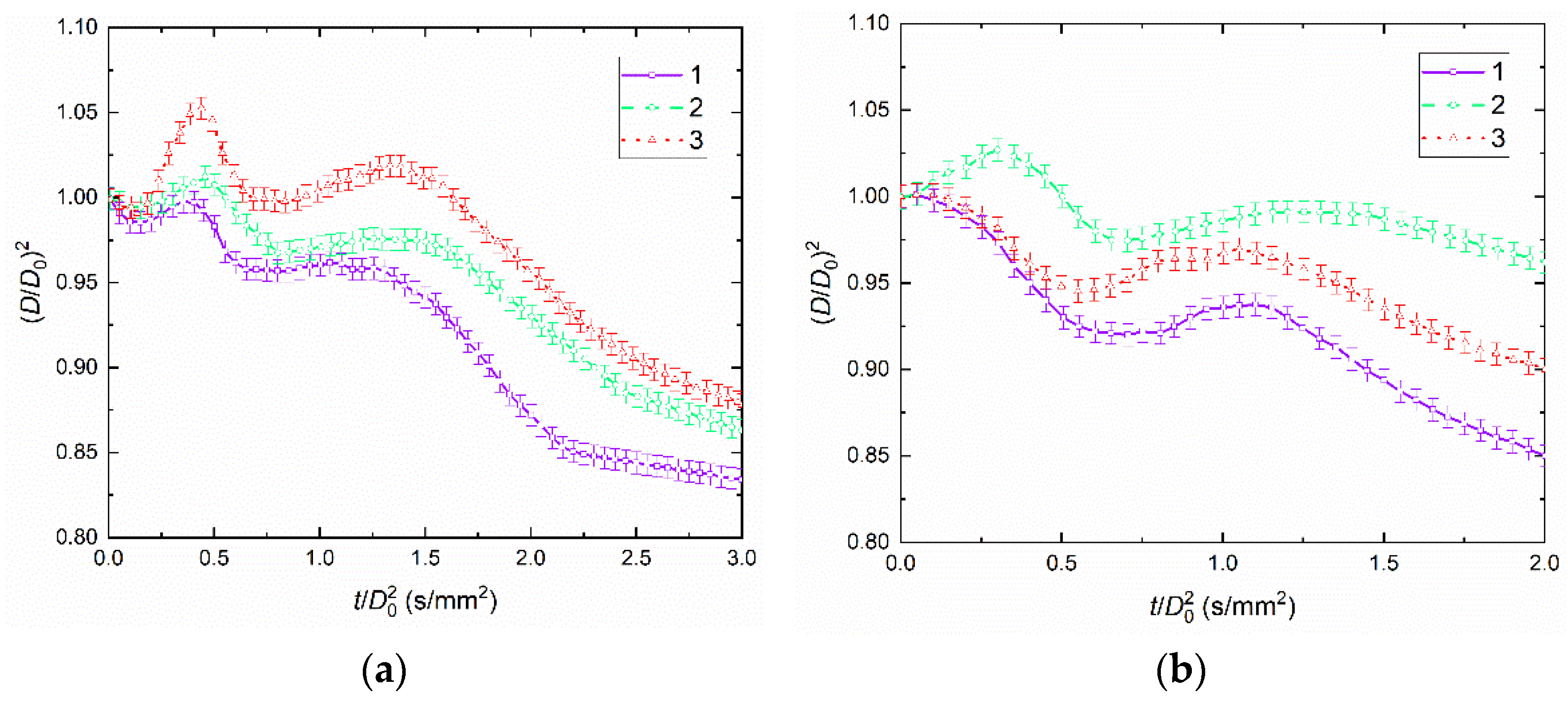
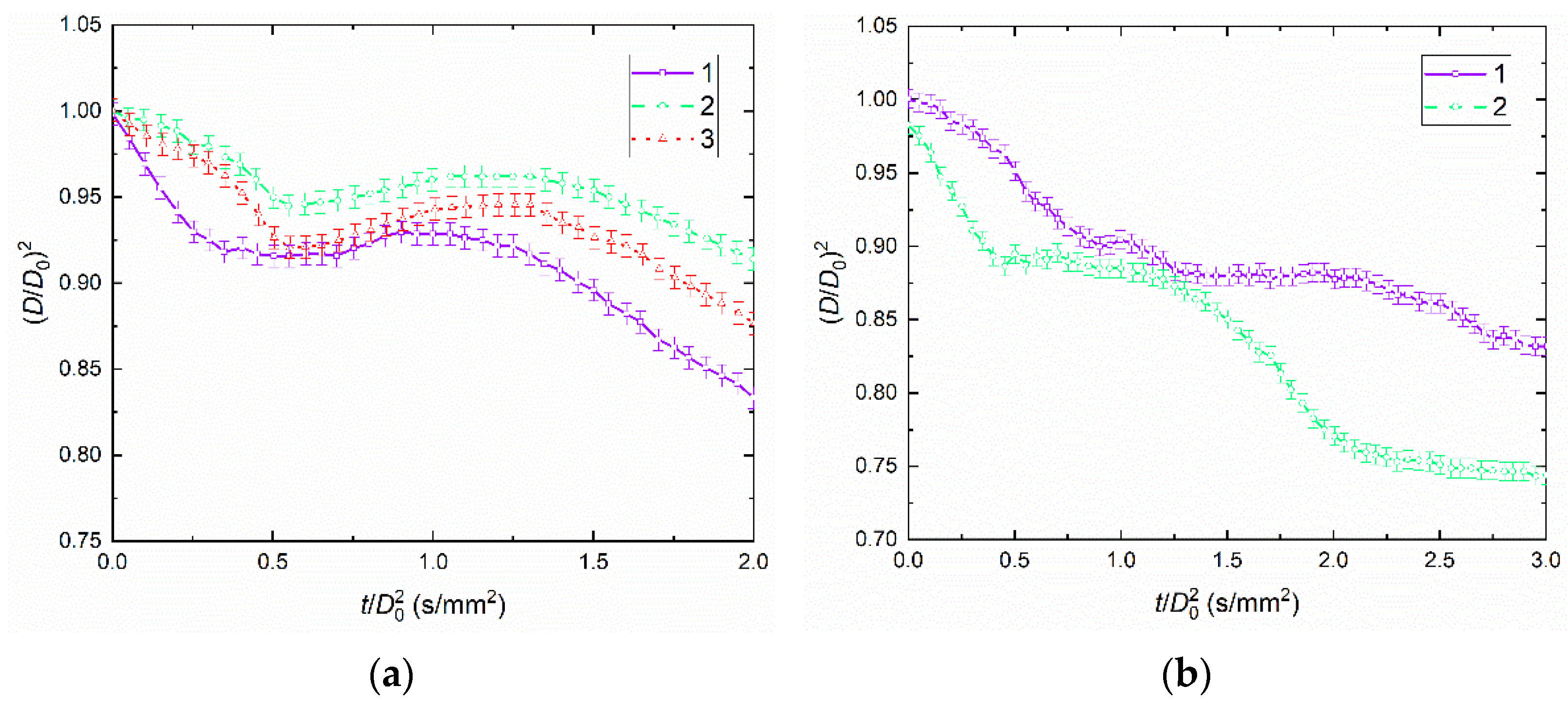
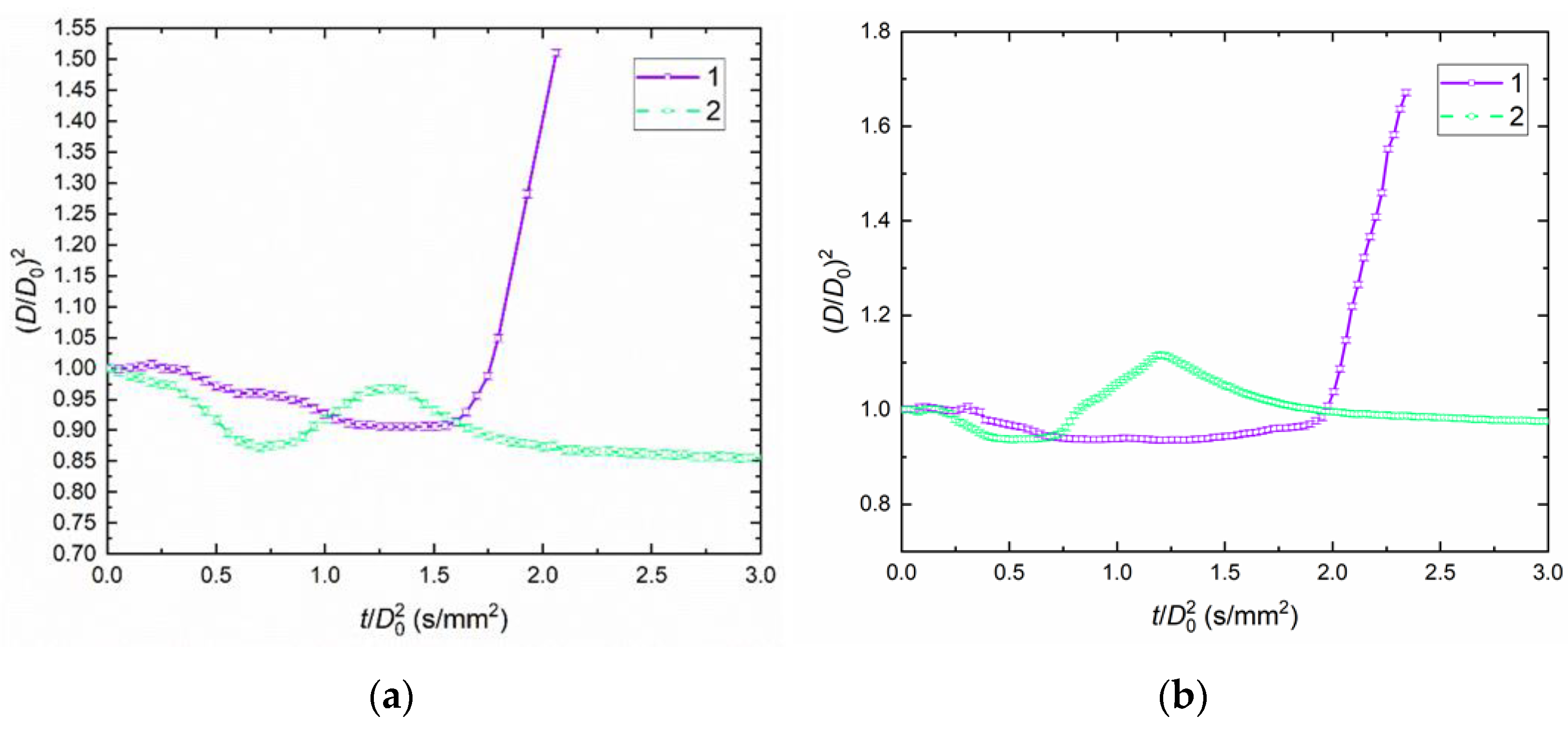
4.2. Temporal Characteristics of Droplet Evaporation, Drying, and Breakup

Figure 4a shows the temporal characteristics of the liquid film evaporation and near-surface layer dehydration before the breakup of K50W49LI1 droplets. Note that droplet breakup was always earlier than droplet ignition. You can clearly see (Figure 4a) the consecutive stages of droplet swelling, vapor filling the pores, and droplets growing in size due to an increase in the pressure inside the pores filled with water vapor throughout the ambient temperature range from 950 to 1150 K. Then, we observe a decrease in the droplet size by up to (D/D0)2 ≈ 0.8–0.85 until all the moisture evaporates. The maximum value of (D/D0)2 ≈ 1.05 was recorded at Ta ≈ 1150 K. Figure 4b presents the temporal characteristics of K50W49D1 droplet evaporation and drying until breakup. Just as Figure 4a, Figure 4b shows the consecutive stages of droplet swelling, vapor filling the pores, and droplets growing in size due to an increase in the pressure inside the pores filled with water vapor throughout the temperature range from 950 to 1150 K. The droplet size then decreases by up to (D/D0)2 ≈ 0.8–0.85 until all the moisture evaporates, as in Figure 4a. The typical time of droplet swelling (initial size increase) did not exceed 2 s, the time of water vapor filling the pores was up to 5 s until the subsequent size increase began, and the droplet size decreases until full moisture evaporation took up to 15 s. The maximum value of (D/D0)2 ≈ 1.05 was recorded at Ta ≈ 1150 K. Overall, droplets of slurry fuels under study exhibited quite a moderate size increase compared to emulsion droplets and immiscible two-liquid droplets studied earlier [42]. This result should be underlined as the most significant one, because it demonstrates the limited conditions of droplet swelling as droplets travel in a slurry fuel jet. This makes spraying more even, minimizes droplet enlargement near the atomizer head, increases the distance covered by the fuel jet in the combustion chamber, and improves the efficiency of the fuel filling the chamber. Otherwise, due to droplet enlargement at the swelling stage, the jet angle increases due to gravity, and the fuel aerosol fills the chamber to a lesser extent. As a result, more fuel settles on the combustion chamber walls. The fuel combustion efficiency decreases, while the anthropogenic emissions increase. These effects are unlikely for slurry fuels under study because (D/D0)2 < 1.1. The total errors in temporal characteristics of droplet evaporation and drying until breakup were estimated as Δ(D/D0) = ±0.007.
Figure 5a presents the temporal characteristics of droplet evaporation and drying until breakup for blend K50W49R1. The duration of droplet swelling (initial size increase) did not exceed 2 s, the time of water vapor filling the pores was up to 7 s until the subsequent size increase began, and the droplet size decreases until full moisture evaporation took up to 15 s. The maximum value of (D/D0)2 ≈ 1.025 was recorded at Ta ≈ 1050 K. Figure 5b presents the data for blend K50W49LE1. In contrast with Figure 4, Figure 5b shows the consecutive stages of water vapor filling the pores and droplets growing in size due to an increase in the pressure inside the pores filled with water vapor, without the initial droplet size growth, throughout temperature range from 950 to 1150 K. Then, we observe a decrease in the droplet size by up to (D/D0)2 ≈ 0.65–0.75 until all the moisture evaporates. The duration of water vapor filling the pores was up to 12 s until the subsequent size increase began, and the droplet size decreases until full moisture evaporation took up to 8 s. The maximum value of (D/D0)2 ≈ 1 was observed at the initial moment at all ambient gas temperatures.
Figure 6a presents the temporal characteristics of K50W50 droplet evaporation and drying until breakup. Figure 6a, just as Figure 5, presents the consecutive stages of water vapor filling the pores and droplets growing in size due to an increase in the pressure inside the pores filled with water vapor, without the initial droplet size growth, throughout temperature range from 950 to 1150 K. Then, we observe a decrease in the droplet size by up to (D/D0)2 ≈ 0.8–0.85 until all the moisture evaporates. The time of water vapor filling the pores was up to 8 s until the subsequent size increase began, and the droplet size decreases until full moisture evaporation took up to 12 s. The maximum value of (D/D0)2 ≈ 1 was observed at the initial moment at all ambient gas temperatures. Figure 6b presents the data for blend C50W49LI1. It shows that the blends containing sodium lignosulfonate do not exhibit the stages of droplet size growth both at the start of heating due to droplet swelling and in the course of heating when the pores of the fuel blend are filled with water vapor followed by a pressure growth in those pores. This indicates that the addition of sodium lignosulfonate stabilized the fuel composition C50W49LI1 (no droplet swelling or breakup was observed). We only established the times of the fuel composition heating until complete evaporation of moisture from the droplets (15 to 30 s, depending on the initial conditions: droplet size and ambient gas temperature). The lowest value of (D/D0)2 ≈ 0.73 was recorded at Ta ≈ 950 K.
Figure 7a shows that the replacement of filter cake with coal of the same rank triggers a transition of heated droplet behavior from drying to breakup. At the same time, the presence of flammable and nonflammable liquids in the composition was an important condition for droplet breakup. When the low-boiling component reached the critical superheating degrees, it evaporated rapidly. The vapors of the low-boiling component filled the pores of the fuel blend. The subsequent increase in the vapor pressure in the pores led to CWSP droplet fragmentation. The indicator (D/D0)2 increased by up to 1.5 times at Ta ≈ 450 K. Importantly, the droplets broke up actively at relatively low ambient gas temperatures (Ta ≈ 450 K). At higher temperatures (Ta ≈ 950 K), no droplet breakup was observed because CWSP droplets were heated rapidly, the liquid combustible component evaporated, a flammable gas–vapor mixture was formed, and it ignited to form a dense shell on the surface. The pressure of the water vapor formed during water superheating was not enough to break up the parent droplet into an array of small secondary fragments. The critical values of (D/D0)2 did not exceed 1.05. Figure 7b presents the temporal characteristics of C50W49R1 droplet evaporation and drying until breakup. The curves (Figure 7b) are very close in shape to those shown in Figure 7a. However, when rapeseed oil was added as the flammable liquid, the values of (D/D0)2 were up to 1.7 times higher (Figure 7b). This happened because rapeseed oil has higher heat capacity and vaporization heat, and boiling and ignition temperature [33]. A droplet containing rapeseed oil heats rather slowly. Conditions are formed in which the temperature of the liquid/liquid interface can reach the water boiling point. As a result, droplets break up extensively to form fuel aerosol. For these reasons, along with its high fire and explosion safety and environmental indicators [50], rapeseed oil is generally considered the most appealing additive to slurry fuels.
Figure 8a presents the characteristics established for C50W49LE1 droplets. The shape of the curves (Figure 8a) is very close to that shown in Figure 7. However, when soy lecithin was added, we recorded low values of (D/D0)2—up to 1.2 times lower than without it (Figure 8a). Figure 8b presents the temporal characteristics of C50W50 droplet evaporation and drying until breakup. We found that coal-based CWSP droplets without additives do not break up. CWSP droplet breakup is triggered by the flammable liquid intensifying water vaporization and vapor filling the droplet pores. In other words, the vaporization centers in the form of coal particles are not enough to intensify breakup when a blend does not contain a liquid combustible component. A liquid combustible component plays an important role for a number of reasons. First, owing to high absorption properties, the liquid combustible component intensifies the accumulation of the radiant energy supplied to the droplet, and more heat is accumulated in the deeper layers. Second, the high viscosity of a flammable liquid provides the cohesion of all the droplet components, its near-surface layer is reinforced, the energy supplied is accumulated, and the vapor bubbles nucleating at the water/flammable liquid interface are retained, growing inside the droplet and deforming it, so favorable conditions are created for droplet breakup in the microexplosion regime. Third, the evaporation of the liquid combustible component leads to higher concentrations of flammable gases near the droplet surface. This intensifies the energy accumulation in this zone due to gas radiation. Moreover, the initiation of chemical reactions in this zone intensifies droplet heating and accelerates its destruction.
The trends presented in this section make it possible to track the stages of droplet surface deformation on heating. When constructed in a unified coordinate system, these trends deepen the insight into the principal differences between the evaporation, swelling, boiling, and breakup of droplets with different component compositions. These patterns are necessary to develop up-to-date models simulating the size variation dynamics of multicomponent droplets in combustion chambers during injection and subsequent atomization. The trends demonstrate the contribution of each component to the processes under study, i.e., at which stage this or that component begins to play a fundamental role, for instance, slowing down or accelerating droplet evaporation, swelling, and breakup. It is especially important to single out the trends for different ambient gas temperatures. They are necessary for the rational choice of temperature ranges providing the maximum droplet surface deformation and the generation of an aerosol cloud with the largest possible number of secondary fragments.
The experimental footage has shown that the breakup process caused a certain volume of the droplet to break off from the holder. Quite a large volume of the droplet remained on the holder. The ratios of the escaping and puffing volume of the liquid to the volume remaining on the holder varied considerably in the experiments with different component compositions. For instance, no more than 20% of the initial droplet volume puffed in the experiments with the compositions based on filter cake. However, in the experiments with droplets containing water, coal, and a liquid combustible component, more than 90% of the initial droplet volume disintegrated and broke up into an array of small fragments. These processes heavily depended on ambient conditions (air flow temperature and velocity) and droplet sticking to the holder surface. Then, due to boiling and rapid evaporation followed by ignition, a solid crust was formed on the holder surface, which increased the surface roughness and the surface area. These conditions intensified heat and mass transfer, phase transitions, and chemical reactions. Such effects do not manifest themselves in real combustion chambers due to the absence of metal holders, but the sequence of processes and phenomena occurring when droplets are injected into combustion chambers and stick to their walls are similar. To minimize these effects, it is important to add liquid combustible components to slurries based on filter cakes and other coal processing wastes. Coal-based slurries are less susceptible to these effects. That is why the injector settings for spraying two- and three-component coal-based mixtures can be varied in a wider range.
The critical durations of droplet heating until breakup obtained in this research can help predict the typical distances covered by droplets in combustion chambers. In this research, the initial sizes of fuel droplets were chosen as somewhat larger (1–1.5 mm) than recommended for spraying (as a rule, 50 to 250 μm) [51] in the combustion chambers of power plants. This is motivated by our commitment to considering all the stages of the processes under study in detail, tracking the patterns of droplet surface deformation, and specifying the contribution of each component to the processes of evaporation, boiling, breakup, and ignition. The experimental data obtained earlier for a wide range of droplet sizes (0.5 μm to 1.5 mm) [42] and microexplosive breakup models [22] make it possible to predict the critical conditions (in particular, the sufficient temperatures and typical heating durations) for the breakup of droplets with compositions similar to those presented in this research. In particular, if the initial droplet size of coal–water slurries with and without petrochemicals is reduced to 250 μm, the typical durations of their heating until intense breakup do not exceed 0.5 s. The results of the corresponding predictions are important for determining the composition-specific critical and advisable conditions of intense droplet breakup in combustion chambers.
The droplet diameter ratios at different stages of their heating and deformation presented in this research make it possible to predict the variation ranges in the droplet surface area ratios throughout their lifetime. These ratios are important for estimating the intensity of droplet heat exchange in combustion chambers. For instance, it was established that ratio of the surface area of secondary fragments to the initial surface area of the parent droplet was 5–10 for the conditions under study. The maximum value equaled 10 and corresponded to the compositions containing rapeseed oil and coal. These values are clearly lower than those reached by two-liquid droplets without solid particles: 100 to 200 [42]. The main reason is in the fundamental role of solid particles in the droplet composition. These particles agglomerated actively within a droplet due to their high relative concentrations. The resulting agglomerates only broke up after the surface and pore space became significantly drier. Thus, the secondary to initial droplet surface area ratios can be increased by minimizing the proportion of solid particles in droplets or by increasing the heating times until water boiling.
The analysis of droplet breakup behavior in a gas at maximum ambient gas temperatures has established that the stages of droplet breakup and ignition may alternate. This happens due to several simultaneous processes. Which of these that occurs first is important. For instance, if a droplet contains a flammable liquid with a high vaporization rate (diesel) and a solid combustible component with a high percentage of volatile substances (brown and bituminous coals), then high-temperature heating leads to a relatively fast gas-phase ignition. This process accelerates the increase in the number of pores in the droplet and intensifies its breakup into a cloud of small liquid fragments. If a droplet contains filter cake, its ignition leads to the formation of a dense solid crust on the surface of an agglomerate of solid particles. This effect slows down the droplet surface deformation and breakup.
The analysis of the experimental footage helped us identify a crucial role of the air flow oncoming on a droplet when determining the conditions of its intense breakup. This role is quite significant for all the component compositions under study. The influence of the air flow manifested itself in the intensification of the moisture evaporation from the near-surface layer of a droplet, its surface deformation due to the growing aerodynamic forces, the increase in the number and sizes of the pores in a multicomponent droplet, and the separation of solid particles and small volumes of liquid from the surface. In the experiments, a droplet was suspended on a holder, which prevented its swirling. As the droplet falls, its surface deforms more intensely due to the droplet translation and rotation. That is why the role of the oncoming air flow will be more significant in real furnaces than in the experiments.
The scattering of the experimental data on the duration of a typical breakup stage did not exceed 0.2 s, and the data on critical diameters did not scatter by more than 0.05 mm. The main reasons for the scattering were as follows: initial droplet size and shape oscillations from one experiment to another, vibration of the experimental setup, and the variable parameters of the environment (pressure, humidity, etc.). The analysis shows how much the value of the characteristics under study can potentially deviate for different applications, fuel types, thermal conditions, and combustion chamber designs.

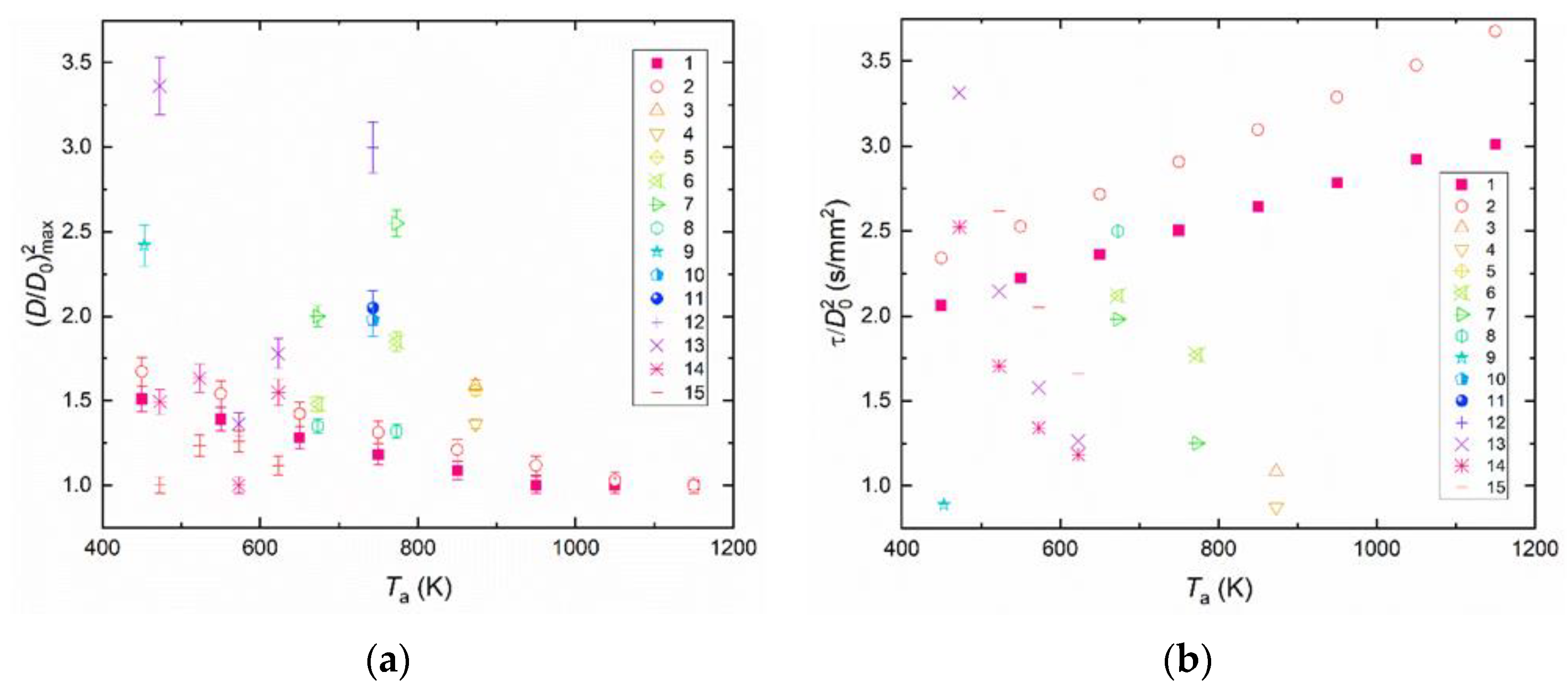
4.3. Generalization of Experimental Data

According to the analysis presented in Figure 4, Figure 5, Figure 6, Figure 7 and Figure 8, droplets of stabilized fuels do not break up unless they contain a flammable liquid. Figure 9 presents the generalized experimental data on the maximum values of (D/D0)2 (a) and τ/(D0)2 (b) against temperature for different puffing fuel compositions described in this paper together with compositions with a small share of solid components (slurries) and without them (typical two-liquid droplets), as presented in earlier works [52,53,54,55,56]. The curves show clearly that the value of (D/D0)2max can reach 3.5 for nonstabilized fuels and does not exceed 1.75 for stabilized ones. The higher values of (D/D0)2max at low temperatures are also an interesting and important result. In the case of fuels with added solid particles, this is caused by the solid crust formed at high temperatures and preventing the droplets from enlarging before breakup. As for fuels without solid particles, this happens because the total breakup conditions are achieved at smaller critical radii of bubbles.
The experimental findings have shown that stabilizing additives have a countervailing effect on droplet heating and breakup behavior. In such cases, it is important to determine the droplet breakup efficiency factor reflecting the heating delay, the required ambient gas temperature, the average size and number of secondary fragments, and the increase in the liquid surface area. The corresponding relative efficiency factor of secondary atomization in the microexplosive breakup regime have the maximum values at the minimum breakup delay times, sufficient ambient gas temperature, and maximum number of secondary fragments with their minimum size. Using the multicriteria comparative analysis [15,57], we generalized the experimental data obtained for the stabilized blends of C50W49D1 and C50W49R1, and the two-liquid droplets of water/kerosene, water/diesel, and water/rapeseed oil [56] according to the following formula: P = T g m i n ¯ × ( D / D 0 ) m a x 2 ¯ × τ ¯ , where T g m i n ¯ = T g m i n 450 is the relative gas temperature limit of droplet breakup, ( D / D 0 ) m a x 2 ¯ = ( D / D 0 ) m a x 2 3 . 36111 is the relative maximum normalized droplet diameter, and τ ¯ = 1.18356 τ is the relative droplet breakup time. Constant values in the equation for P refer to the case of two-liquid droplets without coal particles [38].
It was established (Figure 10) that the maximum value of the droplet microexplosion efficiency factor was 0.98 and it was typical of the compositions containing water/kerosene. These values correlate with the earlier studied emulsified compositions and two-liquid droplets [42]. The efficiency factor was 0.95–1 for such compositions. The values of this efficiency factor may reach 1 given the required ambient gas temperature, heat flux, initial droplet size, and component composition. Stabilization of fuel slurries is one of the key factors for industrial use. The fuel blends used in the experiments are notable for rather high sedimentation stability providing the required slurry storage time (about four days of fuel reserves for typical power-generating facilities: boiler units and thermal power stations). The use of stabilizing additives (soy lecithin, sodium lignosulfonate, rapeseed oil, and diesel) does not only provide high stability by building a well-ordered structure of a fuel blend but also increases the blend viscosity by about 1.5 times. In some cases, however, the fluidity class of the samples may change (transition from class A to class B) while the viscosity remains within the allowable values not exceeding η = 1000–1200 mPa·s for the industrial use of slurries. The results obtained create objective premises for developing the technologies of slurry fuel droplet cloud ignition in combustion chambers of boiler units accounting for stabilizing additives and the ranges of optimal temperatures and initial droplet sizes, as listed in Table 4.

5. Conclusions

(i)
Soy lecithin and sodium lignosulfonate are the most promising stabilizing additives to slurry fuels. The conditions for the intense droplet breakup were not observed when analyzing the parameter (D/D0)2. The value of this parameter did not exceed 1. The transition between slurry droplet breakup regimes depends most heavily on the addition of a flammable liquid (diesel fuel or rapeseed oil) as well as replacement of filter cake with coal. The parameter (D/D0) reached 1.7 during CWSP droplet breakup.
(ii)
The slurry droplet breakup delay time was most significantly affected by the addition of a flammable liquid: diesel fuel or rapeseed oil. The shortest breakup delay times were recorded for the compositions containing diesel fuel as the flammable liquid. In the initial droplet size range from 0.95 to 1.15 mm, the breakup delay times did not exceed 10 s. The properties of child droplets were most significantly influenced by the addition of a flammable liquid: diesel fuel or rapeseed oil. CWSP droplets based on diesel exhibit higher child-droplet velocities and smaller size than droplets based on rapeseed oil. The sizes of child droplets fell into a range of 10 to 140 μm, and their velocities ranged from 0 to 50 m/s.
(iii)
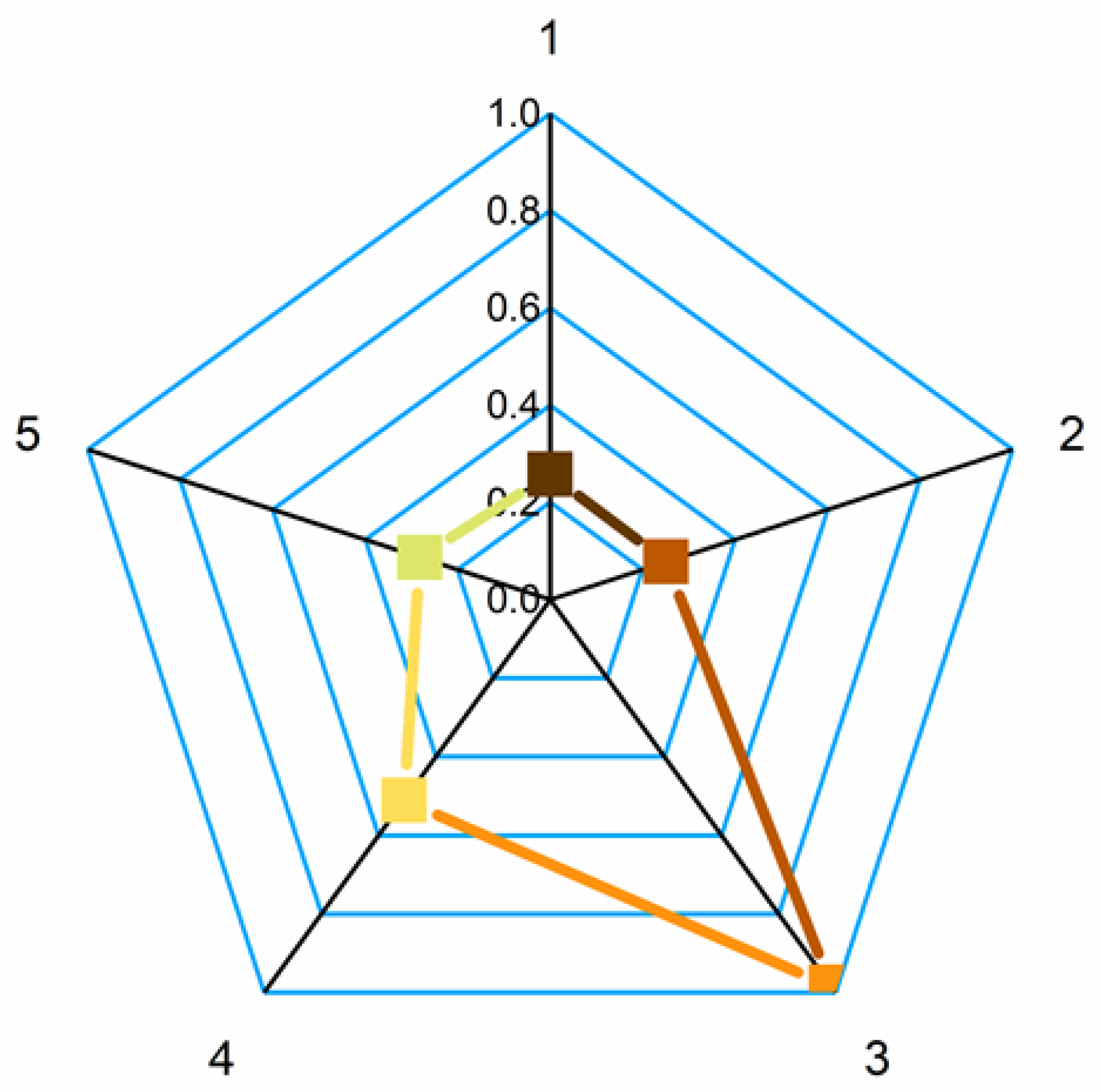
A comparative analysis of slurry fuel droplet stabilization and breakup conditions revealed the most promising conditions of their preparation for storage, transportation, and primary and secondary atomization. The efficiency factor values were calculated for the secondary atomization of promising fuel droplets induced by microexplosive breakup. These values ranged from 0.25 to 1. The maximum values (0.95–1) corresponded to water/kerosene droplets.

Supplementary Materials

The following supporting information can be downloaded at: https://www.mdpi.com/article/10.3390/app122312271/s1, Video S1: Supplementary material A, Video S2: Supplementary material B.

Author Contributions

Conceptualization, G.V.K.; data curation, D.S.R.; funding acquisition, G.V.K.; investigation, D.V.A. and D.S.R.; writing—original draft, D.V.A.; writing—review and editing, G.V.K. and D.V.A. All authors have read and agreed to the published version of the manuscript.

Funding

The research was supported by the Tomsk Polytechnic University (TPU) development program, Priority 2030 (Priority-2030-NIP/EB-038-1308-2022).

Institutional Review Board Statement

Not applicable.

Informed Consent Statement

Not applicable.

Conflicts of Interest

The authors declare no conflict of interest.

References

  1. Munawer, M.E. Human Health and Environmental Impacts of Coal Combustion and Post-Combustion Wastes. J. Sustain. Min. 2018, 17, 87–96. [Google Scholar] [CrossRef]
  2. Xue, Y.; Tian, H.; Yan, J.; Zhou, Z.; Wang, J.; Nie, L.; Pan, T.; Zhou, J.; Hua, S.; Wang, Y.; et al. Temporal Trends and Spatial Variation Characteristics of Primary Air Pollutants Emissions from Coal-Fired Industrial Boilers in Beijing, China. Environ. Pollut. 2016, 213, 717–726. [Google Scholar] [CrossRef] [PubMed]
  3. Ayhan, V.; Tunca, S. Experimental Investigation on Using Emulsified Fuels with Different Biofuel Additives in a DI Diesel Engine for Performance and Emissions. Appl. Therm. Eng. 2018, 129, 841–854. [Google Scholar] [CrossRef]
  4. Xie, J.; Zhong, W.; Shao, Y.; Zhou, G. Simulation of Co-Gasification of Coal and Wood in a Dual Fluidized Bed System. Adv. Powder Technol. 2021, 32, 52–71. [Google Scholar] [CrossRef]
  5. Glushkov, D.; Nyashina, G.; Medvedev, V.; Vershinina, K. Relative Environmental, Economic, and Energy Performance Indicators of Fuel Compositions with Biomass. Appl. Sci. 2020, 10, 2092. [Google Scholar] [CrossRef] [Green Version]
  6. Nyashina, G.; Legros, J.C.; Strizhak, P. Environmental Potential of Using Coal-Processing Waste as the Primary and Secondary Fuel for Energy Providers. Energies 2017, 10, 405. [Google Scholar] [CrossRef] [Green Version]
  7. Vershinina, K.; Dorokhov, V.; Romanov, D.; Nyashina, G.; Kuznetsov, G. Multi-Criteria Efficiency Analysis of Using Waste-Based Fuel Mixtures in the Power Industries of China, Japan, and Russia. Appl. Sci. 2020, 10, 2460. [Google Scholar] [CrossRef] [Green Version]
  8. Akhmetshin, M.R.; Nyashina, G.S.; Strizhak, P.A. Comparative Analysis of Factors Affecting Differences in the Concentrations of Gaseous Anthropogenic Emissions from Coal and Slurry Fuel Combustion. Fuel 2020, 270, 117581. [Google Scholar] [CrossRef]
  9. Staroń, A.; Kowalski, Z.; Staroń, P.; Banach, M. Studies on CWL with Glycerol for Combustion Process. Environ. Sci. Pollut. Res. 2019, 26, 2835–2844. [Google Scholar] [CrossRef] [Green Version]
  10. Wainwright, E.R.; Lakshman, S.V.; Leong, A.F.T.; Kinsey, A.H.; Gibbins, J.D.; Arlington, S.Q.; Sun, T.; Fezzaa, K.; Hufnagel, T.C.; Weihs, T.P. Viewing Internal Bubbling and Microexplosions in Combusting Metal Particles via X-Ray Phase Contrast Imaging. Combust. Flame 2019, 199, 194–203. [Google Scholar] [CrossRef]
  11. Alekseenko, S.V.; Anufriev, I.S.; Dekterev, A.A.; Kuznetsov, V.A.; Maltsev, L.I.; Minakov, A.V.; Chernetskiy, M.Y.; Shadrin, E.Y.; Sharypov, O.V. Experimental and Numerical Investigation of Aerodynamics of a Pneumatic Nozzle for Suspension Fuel. Int. J. Heat Fluid Flow 2019, 77, 288–298. [Google Scholar] [CrossRef] [Green Version]
  12. Tavangar, S.; Hashemabadi, S.H.; Saberimoghadam, A. CFD Simulation for Secondary Breakup of Coal-Water Slurry Drops Using OpenFOAM. Fuel Process. Technol. 2015, 132, 153–163. [Google Scholar] [CrossRef]
  13. Li, P.W.; Yang, D.J.; Lou, H.M.; Qiu, X.Q. Study on the Stability of Coal Water Slurry Using Dispersion-Stability Analyzer. Ranliao Huaxue Xuebao/J. Fuel Chem. Technol. 2008, 36, 524–529. [Google Scholar] [CrossRef]
  14. Glushkov, D.O.; Lyrshchikov, S.Y.; Shevyrev, S.A.; Strizhak, P.A. Burning Properties of Slurry Based on Coal and Oil Processing Waste. Energy Fuels 2016, 30, 3441–3450. [Google Scholar] [CrossRef]
  15. Kumar, A.; Sah, B.; Singh, A.R.; Deng, Y.; He, X.; Kumar, P.; Bansal, R.C. A Review of Multi Criteria Decision Making (MCDM) towards Sustainable Renewable Energy Development. Renew. Sustain. Energy Rev. 2017, 69, 596–609. [Google Scholar] [CrossRef]
  16. Gaber, C.; Wachter, P.; Demuth, M.; Hochenauer, C. Experimental Investigation and Demonstration of Pilot-Scale Combustion of Oil-Water Emulsions and Coal-Water Slurry with Pronounced Water Contents at Elevated Temperatures with the Use of Pure Oxygen. Fuel 2020, 282, 118692. [Google Scholar] [CrossRef]
  17. Hammerton, J.M.; Li, H.; Ross, A.B. Char-Diesel Slurry Fuels for Microgeneration: Emission Characteristics and Engine Performance. Energy 2020, 207, 118225. [Google Scholar] [CrossRef]
  18. Staroń, A.; Kowalski, Z.; Staroń, P.; Banach, M. Analysis of the Useable Properties of Coal-Water Fuel Modified with Chemical Compounds. Fuel Process. Technol. 2016, 152, 183–191. [Google Scholar] [CrossRef]
  19. Glushkov, D.O.; Strizhak, P.A.; Chernetskii, M.Y. Organic Coal-Water Fuel: Problems and Advances (Review). Therm. Eng. 2016, 63, 707–717. [Google Scholar] [CrossRef]
  20. Antonov, D.V.; Kuznetsov, G.V.; Strizhak, P.A. Differences of Two-Component Droplets Breakup at the High Temperatures. J. Energy Inst. 2019, 93, 351–366. [Google Scholar] [CrossRef]
  21. Moussa, O.; Tarlet, D.; Massoli, P.; Bellettre, J. Investigation on the Conditions Leading to the Micro-Explosion of Emulsified Fuel Droplet Using Two Colors LIF Method. Exp. Therm. Fluid Sci. 2020, 116, 110106. [Google Scholar] [CrossRef]
  22. Sazhin, S.S.; Bar-Kohany, T.; Nissar, Z.; Antonov, D.; Strizhak, P.A.; Rybdylova, O.D. A New Approach to Modelling Micro-Explosions in Composite Droplets. Int. J. Heat Mass Transf. 2020, 161, 120238. [Google Scholar] [CrossRef]
  23. Antonov, D.V.; Nyashina, G.S.; Strizhak, P.A.; Romanov, D.S. Micro-Explosive Droplet Fragmentation of Environmentally Promising Coal-Water Slurries Containing Petrochemicals. Fuel 2021, 283, 118949. [Google Scholar] [CrossRef]
  24. Piskunov, M.; Romanov, D.; Strizhak, P.; Yanovsky, V. Individual and Synergistic Effects of Modifications of the Carrier Medium of Carbon-Containing Slurries on the Viscosity and Sedimentation Stability. Chem. Eng. Res. Des. 2022, 184, 191–206. [Google Scholar] [CrossRef]
  25. Yaws, C.L. Yaws’ Handbook of Thermodynamic and Physical Properties of Chemical Compounds; Knovel: New York, NY, USA, 2003. [Google Scholar]
  26. Zhang, Y.; Hu, S.; Yang, X.; Jiang, F.; Wu, C.; Li, J.; Liu, K. Performance and Mechanism of Polyacrylamide Stabilizers in Coal Water Slurry. Colloids Surfaces A Physicochem. Eng. Asp. 2021, 630, 127544. [Google Scholar] [CrossRef]
  27. ISO 1928:2009; TAPPI Solid Mineral Fuels—Determination of Gross Calorific Value by the Bomb Calorimetric Method and Calculation of Net Calorific Value. TAPPI Test Methods. ISO: Geneva, Switzerland, 2009; Volum 1995.
  28. ASTM International. Standard Test Method for Heat of Combustion of Liquid Hydrocarbon Fuels by Bomb Calorimeter; ASTM International: West Conshohocken, PA, USA, 2018. [Google Scholar]
  29. Ibraeva, K.T.; Manaev, Y.O.; Tabakaev, R.B.; Yazykov, N.A.; Zavorin, A.S. Research of Characteristics and Mineral Composition of Peat of the Tomsk Region Relating to Energy Use. Bull. Tomsk Polytech. Univ. Geo Assets Eng. 2019, 330. [Google Scholar] [CrossRef]
  30. ASTM International. Standard Test Methods for Determination of Carbon, Hydrogen and Nitrogen in Analysis Samples of Coal and Carbon in Analysis Samples of Coal and Coke 1; ASTM International: West Conshohocken, PA, USA, 2016. [Google Scholar]
  31. Antonov, D.; Bellettre, J.; Tarlet, D.; Massoli, P.; Vysokomornaya, O.; Piskunov, M. Impact of Holder Materials on the Heating and Explosive Breakup of Two-Component Droplets. Energies 2018, 11, 3307. [Google Scholar] [CrossRef] [Green Version]
  32. Vysokomornaya, O.V.; Piskunov, M.V.; Strizhak, P.A. Breakup of Heterogeneous Water Drop Immersed in High-Temperature Air. Appl. Therm. Eng. 2017, 127, 1340–1345. [Google Scholar] [CrossRef]
  33. Antonov, D.V.; Fedorenko, R.M.; Strizhak, P.A.; Nissar, Z.; Sazhin, S.S. Puffing/Micro-Explosion in Composite Fuel/Water Droplets Heated in Flames. Combust. Flame 2021, 233, 111599. [Google Scholar] [CrossRef]
  34. Tarlet, D.; Allouis, C.; Bellettre, J. The Balance between Surface and Kinetic Energies within an Optimal Micro-Explosion. Int. J. Therm. Sci. 2016, 107, 179–183. [Google Scholar] [CrossRef]
  35. Khan, M.Y.; Abdul Karim, Z.A.; Aziz, A.R.A.; Tan, I.M. Experimental Investigation of Microexplosion Occurrence in Water in Diesel Emulsion Droplets during the Leidenfrost Effect. Energy Fuels 2014, 28, 7079–7084. [Google Scholar] [CrossRef]
  36. Ismael, M.A.; Heikal, M.R.; Aziz, A.R.A.; Syah, F.; Zainal A., E.Z.; Crua, C. The Effect of Fuel Injection Equipment on the Dispersed Phase of Water-in-Diesel Emulsions. Appl. Energy 2018, 222, 762–771. [Google Scholar] [CrossRef]
  37. Antonov, D.V.; Kuznetsov, G.V.; Strizhak, P.A.; Rybdylova, O.; Sazhin, S.S. Micro-Explosion and Autoignition of Composite Fuel/Water Droplets. Combust. Flame 2019, 210, 479–489. [Google Scholar] [CrossRef]
  38. Antonov, D.V.; Piskunov, M.V.; Strizhak, P.A. Explosive Disintegration of Two-Component Drops under Intense Conductive, Convective, and Radiant Heating. Appl. Therm. Eng. 2019, 152, 409–419. [Google Scholar] [CrossRef]
  39. Antonov, D.V.; Fedorenko, R.M.; Strizhak, P.A. Child Droplets Produced by Micro-Explosion and Puffing of Two-Component Droplets. Appl. Therm. Eng. 2020, 164, 114501. [Google Scholar] [CrossRef]
  40. Tarlet, D.; Mura, E.; Josset, C.; Bellettre, J.; Allouis, C.; Massoli, P. Distribution of Thermal Energy of Child-Droplets Issued from an Optimal Micro-Explosion. Int. J. Heat Mass Transf. 2014, 77, 1043–1054. [Google Scholar] [CrossRef]
  41. Antonov, D.; Piskunov, M.; Strizhak, P.; Tarlet, D.; Bellettre, J. Dispersed Phase Structure and Micro-Explosion Behavior under Different Schemes of Water-Fuel Droplets Heating. Fuel 2020, 259, 116241. [Google Scholar] [CrossRef]
  42. Antonov, D.V.; Piskunov, M.V.; Strizhak, P.A. Breakup and Explosion of Droplets of Two Immiscible Fluids and Emulsions. Int. J. Therm. Sci. 2019, 142, 30–41. [Google Scholar] [CrossRef]
  43. Rosli, M.A.F.; Aziz, A.R.A.; Ismael, M.A.; Elbashir, N.O.; Zainal A., E.Z.; Baharom, M.; Mohammed, S.E. Experimental Study of Micro-Explosion and Puffing of Gas-to-Liquid (GTL) Fuel Blends by Suspended Droplet Method. Energy 2021, 218, 119462. [Google Scholar] [CrossRef]
  44. Avulapati, M.M.; Megaritis, T.; Xia, J.; Ganippa, L. Experimental Understanding on the Dynamics of Micro-Explosion and Puffing in Ternary Emulsion Droplets. Fuel 2019, 239, 1284–1292. [Google Scholar] [CrossRef]
  45. Antonov, D.; Vysokomornaya, O.; Piskunov, M.; Shlegel, N. Analysis of Statistical Data on Drop Collisions in an Aerosol Flow during Experiments. EPJ Web Conf. 2019, 196, 00013. [Google Scholar] [CrossRef] [Green Version]
  46. Volkov, R.S.; Kuznetsov, G.V.; Strizhak, P.A. Water Droplet Deformation in Gas Stream: Impact of Temperature Difference between Liquid and Gas. Int. J. Heat Mass Transf. 2015, 85, 1–11. [Google Scholar] [CrossRef]
  47. Yoon, I.; Shin, S. Maximal Spreading of Droplet during Collision on Particle: Effects of Liquid Viscosity and Surface Curvature. Phys. Fluids 2021, 33, 083310. [Google Scholar] [CrossRef]
  48. Komrakova, A.E.; Shardt, O.; Eskin, D.; Derksen, J.J. Effects of Dispersed Phase Viscosity on Drop Deformation and Breakup in Inertial Shear Flow. Chem. Eng. Sci. 2015, 126, 150–159. [Google Scholar] [CrossRef]
  49. Kuznetsov, G.V.; Islamova, A.G.; Orlova, E.G.; Strizhak, P.A.; Feoktistov, D.V. Physicochemical Features of the Effect of Special Water-Based Fire Retardants on Forest Materials. Fire Saf. J. 2021, 123, 103371. [Google Scholar] [CrossRef]
  50. Antonov, D.V.; Strizhak, P.A. Intensification of Vaporization and Secondary Atomization of Droplets of Fire-Extinguishing Liquid Composition. Tech. Phys. Lett. 2020, 46, 122–125. [Google Scholar] [CrossRef]
  51. Kerimbekova, S.A.; Kuznetsov, G.V.; Volkov, R.S.; Strizhak, P.A. Identification of Slurry Fuel Components in a Spray Flow. Fuel. 2022, 323, 124353. [Google Scholar] [CrossRef]
  52. Wang, J.; Qiao, X.; Ju, D.; Wang, L.; Sun, C. Experimental Study on the Evaporation and Micro-Explosion Characteristics of Nanofuel Droplet at Dilute Concentrations. Energy 2019, 183, 149–159. [Google Scholar] [CrossRef]
  53. Huang, X.; Wang, J.; Wang, Y.; Qiao, X.; Ju, D.; Sun, C.; Zhang, Q. Experimental Study on Evaporation and Micro-Explosion Characteristics of Biodiesel/n-Propanol Blended Droplet. Energy 2020, 205, 118031. [Google Scholar] [CrossRef]
  54. Zhang, X.; Li, T.; Wang, B.; Wei, Y. Superheat Limit and Micro-Explosion in Droplets of Hydrous Ethanol-Diesel Emulsions at Atmospheric Pressure and Diesel-like Conditions. Energy 2018, 154, 535–543. [Google Scholar] [CrossRef]
  55. Rao, D.C.K.; Syam, S.; Karmakar, S.; Joarder, R. Experimental Investigations on Nucleation, Bubble Growth, and Micro-Explosion Characteristics during the Combustion of Ethanol/Jet A-1 Fuel Droplets. Exp. Therm. Fluid Sci. 2017, 89, 284–294. [Google Scholar] [CrossRef] [Green Version]
  56. Fedorenko, R.M.; Antonov, D.V.; Strizhak, P.A.; Sazhin, S.S. Time Evolution of Composite Fuel/Water Droplet Radii before the Start of Puffing/Micro-Explosion. Int. J. Heat Mass Transf. 2022, 191, 122838. [Google Scholar] [CrossRef]
  57. Anwar, M.; Rasul, M.G.; Ashwath, N. The Efficacy of Multiple-Criteria Design Matrix for Biodiesel Feedstock Selection. Energy Convers. Manag. 2019, 198, 111790. [Google Scholar] [CrossRef]
Figure 1. Experimental scheme with an alcohol burner (a); temperature measurement scheme in the recording area (b). The total errors in temperature (time) measurements were estimated as ±45 K (±0.1 s).
Applsci 12 12271 g001
Figure 2. Images showing the evaporation, drying, and breakup of C50W49D1 (a), C50W49LE1 (b), C50W49LI1 (c), C50W49R1 (d), and C50W50 (e) at Ta ≈ 450 K and Rd0 ≈ 1.0 mm.
Applsci 12 12271 g002
Figure 3. The main steps for postprocessing the sizes and shapes of droplets.
Applsci 12 12271 g003
Figure 4. Temporal characteristics of droplet evaporation and drying until breakup for blends K50W49LI1 (a) and K50W49D1 (b) (Rd0 = 1.3 ± 0.1 mm): 1—Ta = 950 ± 30 K; 2—Ta = 1050 ± 30 K; 3—Ta = 1150 ± 30 K.
Applsci 12 12271 g004
Figure 5. Temporal characteristics of droplet evaporation and drying until breakup for blends K50W49R1 (a) and K50W49LE1 (b) (Rd0 = 1.3 ± 0.1 mm): 1—Ta = 950 ± 30 K; 2—Ta = 1050 ± 30 K; 3—Ta = 1150 ± 30 K.
Applsci 12 12271 g005
Figure 6. Temporal characteristics of droplet evaporation and drying until breakup for blends K50W50 (a) and C50W49LI1 (b) (Rd0 = 1.3 ± 0.1 mm): 1—Ta = 950 ± 30 K; 2—Ta = 1050 ± 30 K; 3—Ta = 1150 ± 30 K.
Applsci 12 12271 g006
Figure 7. Temporal characteristics of droplet evaporation and drying until breakup for blends C50W49D1 (a) and C50W49R1 (b) (Rd0 = 1.3 ± 0.1 mm): 1—Ta = 450 ± 30 K; 2—Ta = 950 ± 30 K.
Applsci 12 12271 g007
Figure 8. Temporal characteristics of droplet evaporation and drying until breakup for blends C50W49LE1 (a) and C50W50 (b) (Rd0 = 1.3 ± 0.1 mm): 1—Ta = 450 ± 30 K; 2—Ta = 950 ± 30 K.
Applsci 12 12271 g008
Figure 9. Generalized experimental data on maximum values of (D/D0)2 (a) and τ/(D0)2 (b) vs. gas temperature for different fuel compositions in the course of breakup: 1—C50W49D1 (current study); 2—C50W49R1 (current study); 3—diesel [52]; 4—DCe-0.05 [52]; 5—DCe-0.25 [52]; 6—P25BD75 [53]; 7—P50BD50 [53]; 8—P75BD25 [53]; 9—HE30 [54]; 10—E10 [55]; 11—E30 [55]; 12—E50 [55]; 13—water/kerosene [56]; 14—water/diesel [56]; 15—water/rapeseed oil [56].
Applsci 12 12271 g009
Figure 10. Diagram of relative efficiency indicators for time, maximum values of (D/D0)2max, and critical breakup temperature for the following compositions: 1—C50W49D1; 2—C50W49R1; 3—water/kerosene [56]; 4—water/diesel [56]; 5—water/rapeseed oil [56].
Applsci 12 12271 g010
Table 1. Thermophysical and transport properties of CWS and CWSP components at T = 300 K [14,25].
MaterialProperties
Waterρ = 1010.7 kg/m3; C = 4244.5 J/(kg·K); k = 0.61 W/(m·K); µ = 0.0011 Pa·s; L = 2.44 MJ/kg; Psat = 3324.6 Pa
Rapeseed oilρ = 870.6 kg/m3; C = 2352.1 J/(kg·K); k = 0.17 W/(m·K); µ = 0.0056 Pa·s; L = 0.34 MJ/kg; Psat = 0.0008 Pa
Diesel fuelρ = 743.7 kg/m3; C = 2215.0 J/(kg·K); k = 0.14 W/(m·K); µ = 0.0013 Pa·s; L = 0.35 MJ/kg; Psat = 21.03 Pa
Bituminous coalρ = 1367.1 kg/m3; C = 1293.4 J/(kg·K); k = 0.26 W/(m·K)
Table 2. Ultimate and proximate analysis of filter cake and coals.
SampleWa, %Ad, %Vdaf, %Q, MJ/kgCdaf, %Hdaf, %Ndaf, %Std, %Odaf, %
filter cake26.4623.0824.8387.205.0902.051.0224.46
bituminous coal2.0514.6540.1929.7679.794.4861.840.86813.016
Table 3. Slurry fuels used in the experiments.
Short NameComponents
Filter CakeBituminous CoalWaterSodium LignosulfonateDieselRapeseed OilSoy Lecithin
wt.%wt.%wt.%wt.%wt.%wt.%wt.%
K50W49LI150491
K50W49D150491
K50W49R150491
K50W49LE150491
K50W505050
C50W49LI150491
C50W49D150491
C50W49R150491
C50W49LE150491
C50W505050
Table 4. Viscosity measurements of slurry fuels used in the experiments.
Short NameViscosity at γ = 100 s−1 (mPa·s)
K50W49LI1337.4
K50W49D1640.8
K50W49R1735.4
K50W49LE1431
K50W50324.1
C50W49LI1285.6
C50W49D1277.4
C50W49R1421.9
C50W49LE1589.3
C50W50236.7
Publisher’s Note: MDPI stays neutral with regard to jurisdictional claims in published maps and institutional affiliations.

