1. Introduction
The history of facial deformity correction surgery has evolved through several phases. At first, this surgery was only intended for the correction of the most evident deformities that could not otherwise be corrected by orthodontics alone [
1]. In these situations, it is obvious that the aesthetic objective was secondary to the functional one [
1]. Subsequently, with the progressive reduction in surgical risk, the treatment’s objective shifted progressively from the functional to the aesthetic [
2]; this is also due to modern society increasingly imposing a pleasant facial aspect on people that has become more and more important for social acceptance and self-esteem [
3,
4].
Therefore, since facial aesthetics has become the main reason for orthognathic surgery, it is evident that the anthropometric examination of the face has become more and more crucial in the planning of the sites and extent of skeletal repositioning [
5,
6]. Facial aesthetics, once considered almost only in a profilometric view, is now analysed in the three dimensions of space through increasingly sophisticated methods that allow a very realistic three-dimensional reconstruction of the data and, at the same time, a precise simulation of the surgery and its possible effects on the final harmony of the facial skeleton [
7,
8]. Dento-maxillofacial deformities can be classified as sagittal (class II and III), vertical (long and short face), or asymmetric. However, even in cases where the main problem is sagittal or vertical, an asymmetrical component is often associated. This finding suggests that an asymmetric component is usually present [
9] and the treatment plan must take this into account to achieve the best result [
10]. Correction of these problems is not simple, as it is well known that in asymmetrical deformities the skeletal structures are not normal structures arranged in an asymmetrical position in space [
11]. They are inherently asymmetrical structures because they have grown in a distorted muscular environment [
11]. This is particularly true for the mandible, which in situations of asymmetry generally has quite different borders and angles on the two sides [
12]. Consequently, the correction of a mandibular symmetry cannot be limited to the centring of the chin in relation to the midline of the face but must include a thorough correction of the lateral and angular regions of the face as well, especially in complex cases [
13,
14,
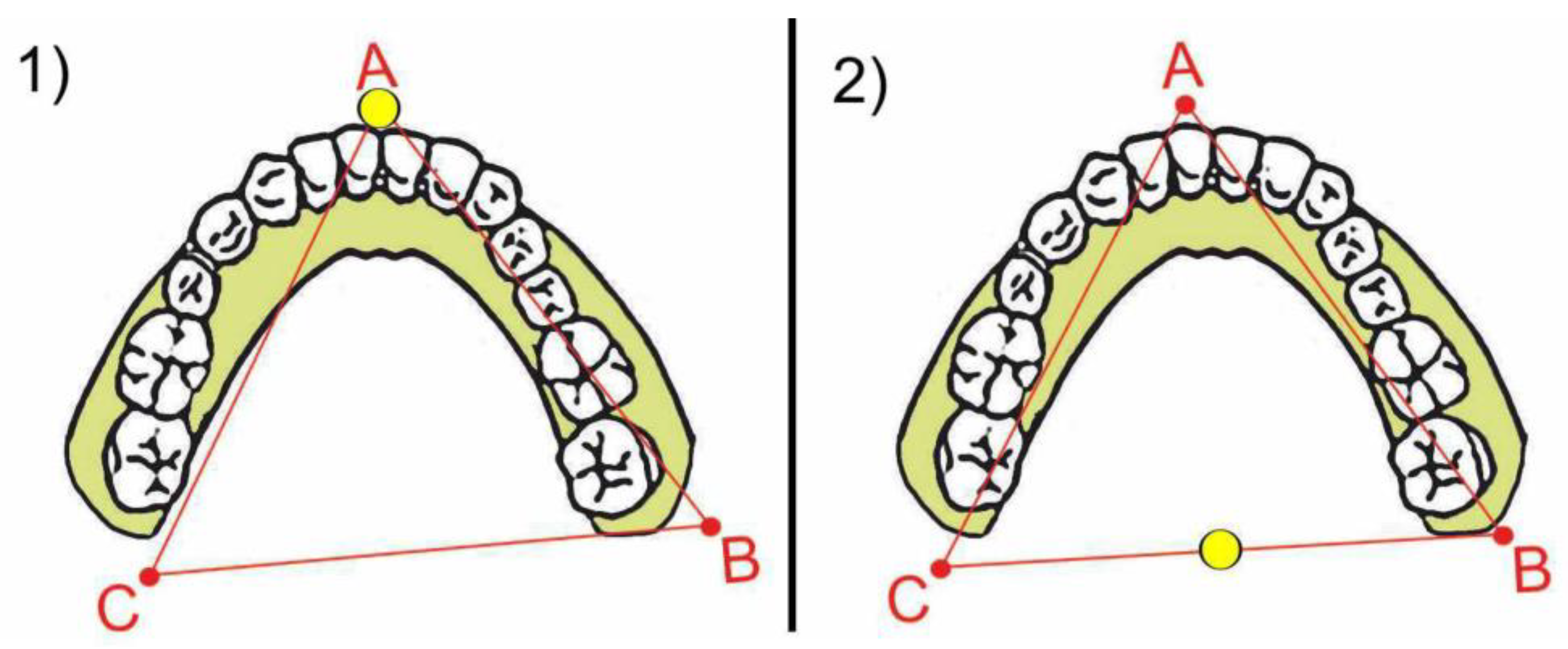
15]. Above all, planning the angular region of the face turns out to be very important to obtain a final harmony of the face that is completely satisfactory for the patient, and it must be conducted with appropriate methods. To understand the movements that the mandible will undergo during surgery, we can imagine the dentition of the lower arch as a triangle defined by three points A, B, and C (
Figure 1).
If the orthodontist has adequately performed the pre-surgical preparation, the dental inter-incisive midline is aligned to the centre of the chin (A point). The two molar regions, right and left, are related to the two angular regions (B and C points). The surgeon can move this triangle in space in various ways. In the sagittal direction, the surgeon can move it forward or backwards to correct a second or third skeletal class malocclusion. The surgeon can also rotate it in various ways to correct an asymmetry. When the centre of rotation shifts near the anterior region, the mandibular angles position will change in the transversal dimension much more than the chin (
Figure 2(1), yellow point). In this example, the centre of rotation is located at A point. Alternatively, when the centre of rotation shifts back near the molar region, the chin position (A point) will shift much more in the transversal dimension than the region of the angles (
Figure 2(2), yellow point).
In this example, the centre of rotation is located between B and C point. It is therefore critical for the surgeon to carefully decide the movements in space of this triangle, both in the sagittal and rotational directions, especially in cases with asymmetry in chin and mandibular angles. In order to decide on these important parameters, the surgeon traditionally has evaluated the so-named “model surgery” technique, that is the simulation of the movements of bone pieces made on plaster models mounted in an articulator. Nowadays, however, the possibility to simulate bone movements on appropriate computer programs based on 3D reconstruction offers numerous advantages.
MODEL SURGERY—In the traditional analogical method, the impressions of the dental arches are developed in plaster and mounted on an articulator using face bow. Between the bases of the articulator and the models is interposed a properly calibrated plaster base, with reference notches allowing a precise repositioning of the models themselves, simulating the desired movements of the bone pieces. The movement of the mandible is analysed for both the anterior median region and the two lateral retro-molar regions. As previously stated, the anterior median region of the lower model represents the repositioning of the chin, i.e., the symmetry of the chin with respect to the midline of the face. The right and left lateral retromolar regions of the plaster model represent the repositioning of the mandibular angles, i.e., the symmetry of the lateral position of the mandibular angles from the midline of the face.
CT PROGRAMMING—In the modern digital method [
16], optical impressions of the arches are superimposed on the CT reconstruction of the maxilla and mandible, thus obtaining the virtual 3D simulation of the patient. This technology is in line with the current quest for ever greater customisation of treatment and pursuit of patient satisfaction, a concept now established in other branches of dentistry [
17,
18,
19]. The osteotomy sections are then simulated on the virtual 3D reconstruction and bone pieces are repositioned according to the established treatment plan. In the CT reconstruction, the best possible repositioning of both the chin symmetry and the symmetry of the mandibular angle regions is directly evident and/or may be related to 3D cephalometric planes.
The Authors believe that programming mandibular angles, if done with the traditional method of articulator-mounted model surgery, fatally leads to an incorrect estimation of the skeletal movements and demonstrates the anatomical reasons for this inaccuracy. The Authors believe that virtual articulator programming is much more efficient in this regard and avoids the mentioned error. The Authors show this concept with a clinical case that illustrates the differences between the two types of programming compared.
2. Materials and Methods
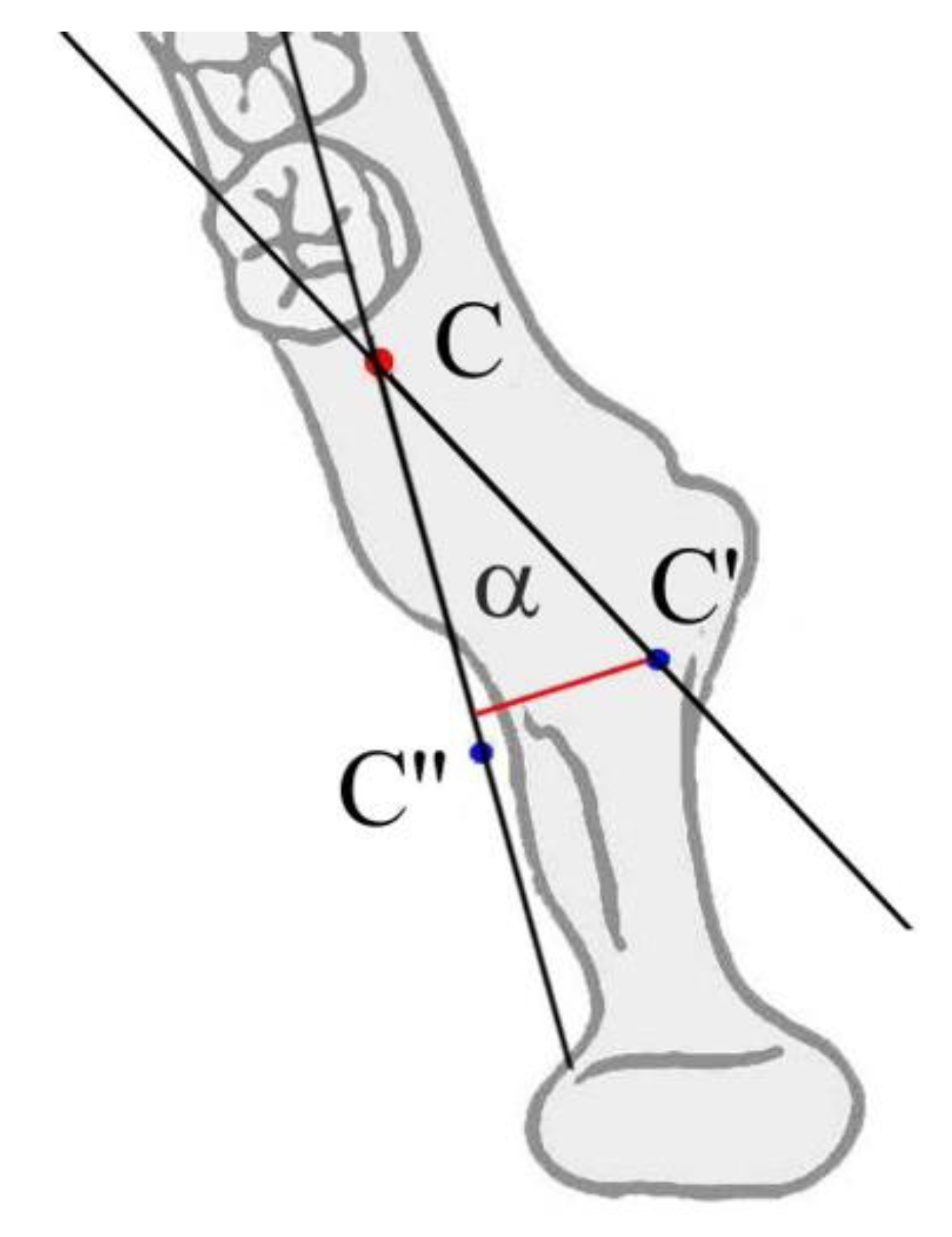
The reason why planning mandibular angles is different in analogical and digital methods consists of the large distance existing between the posterior base of the model (representing in model surgery mandibular angles) and the actual skeletal structure (
Figure 3C–C′,B–B′).
In fact, the plaster model is trimmed just behind the lower molars, while the mandibular angles are located more posteriorly. The same problem does not happen for the chin; in fact, the lower incisors are located very close to the anatomical structure they represent in model surgery. The movement of the dentition is therefore a faithful representation of how the chin will also move in space. Instead, the distance between the molar regions of the dentition and the mandibular angles is greater (
Figure 3B,C versus
Figure 3B′,C′) and the movement of the dentition is therefore no longer a faithful representation of how the mandibular angles will move in space. In the model surgery, the movement of mandibular angles will therefore appear to be less than what actually occurs. The amount of the difference depends on the distance between the molar area and angle and the sine of the angle of surgical rotation (
Figure 4).
The extra movement that the angle of the mandible will undergo, compared to that demonstrated in the model surgery, will be directly proportional to the distance between the molars and the angles and to the sine of the angle of rotation. Obviously, there is also a sagittal component in the movement that the angles undergo, however it is minimal and clinically negligible.
3. Results
In this paper, the Authors point out the real reason that makes the prediction of angular morphology on model surgery particularly difficult.
The problem is related to the distance between the anatomical region of the mandibular angle and the retro molar area; this distance is not reproduced on dental models and makes the prediction unreliable. This error, however, is substantially nullified in the virtual planning of the surgery, which allows a real visualisation of the patient’s maxillo-mandibular complex.
Clinical Case
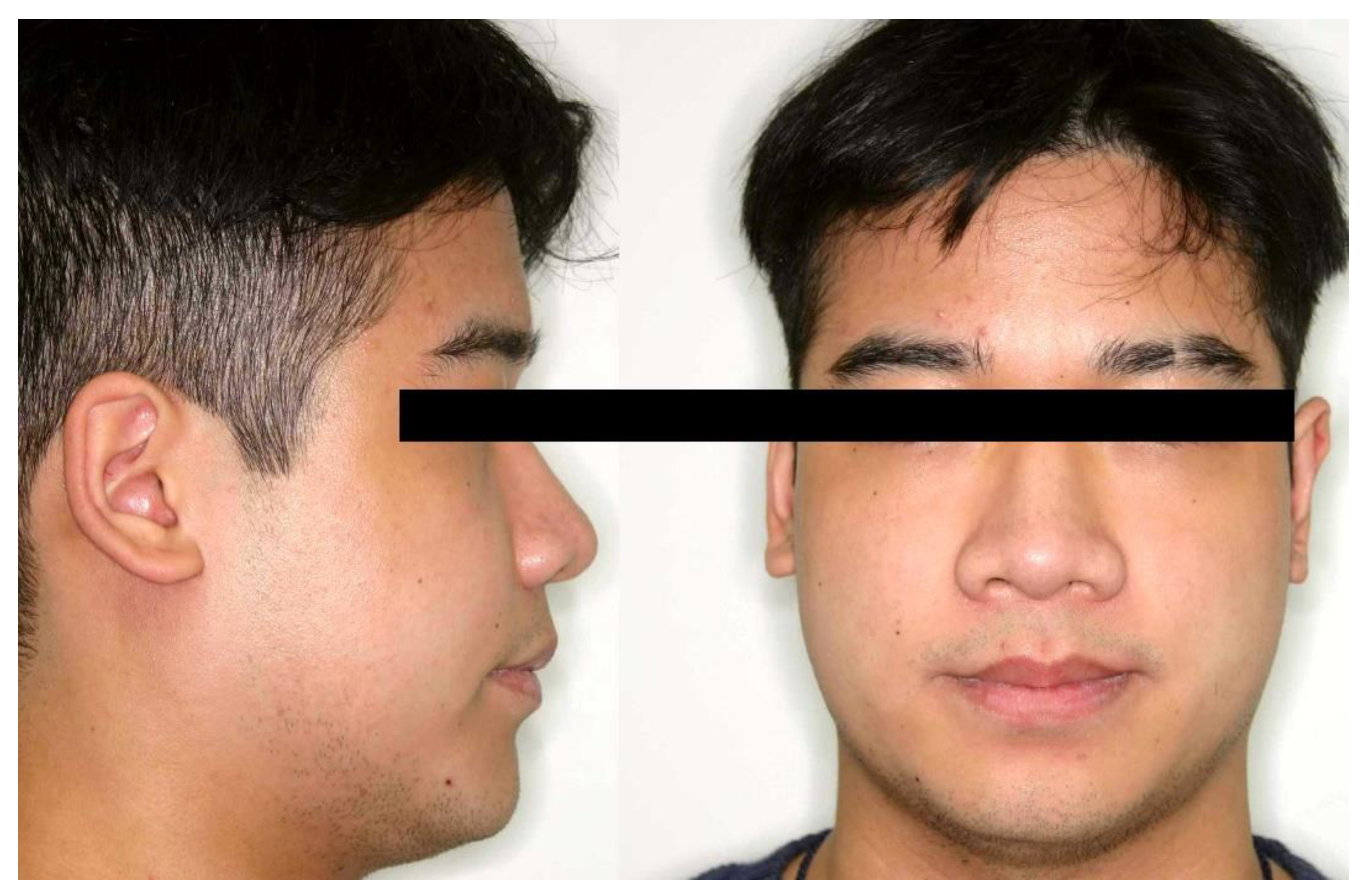
The case presented refers to a young adult male who presented an asymmetric class III skeletal malocclusion (
Figure 5). The chin was deviated to the left and the right angular area was more prominent than the left one (
Figure 6). The patient was disturbed by the protrusion of the chin but also by the evident asymmetry of the lateral aspect of the face.
For this reason, it was very important for the surgeon to plan the correction of the facial skeleton, taking into account both the sagittal and asymmetric components. The dental occlusion was compatible with a “surgery early” approach, so the patient underwent extraction of the lower third molars and a short orthodontic treatment (six months) to correct some dental contacts that would have disturbed postoperative stability, and then operated.
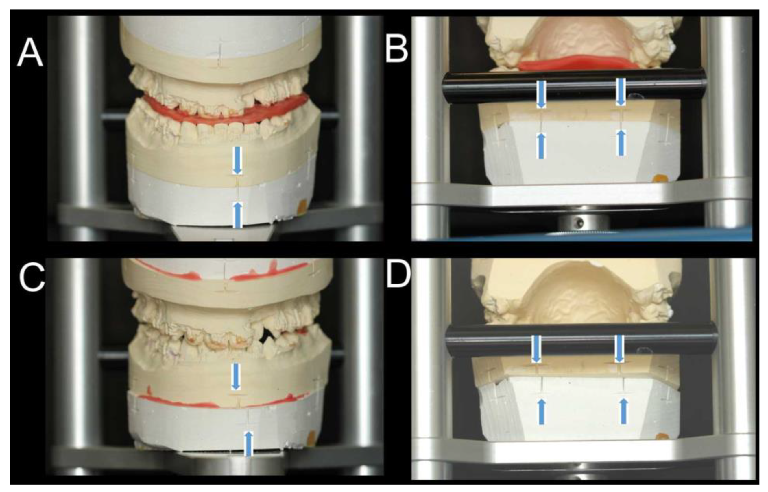
In order to predict the aesthetics of the mandible with maximum precision, planning of the chin correction and angular movements were performed with both model surgery on articulator (
Figure 7—SAM
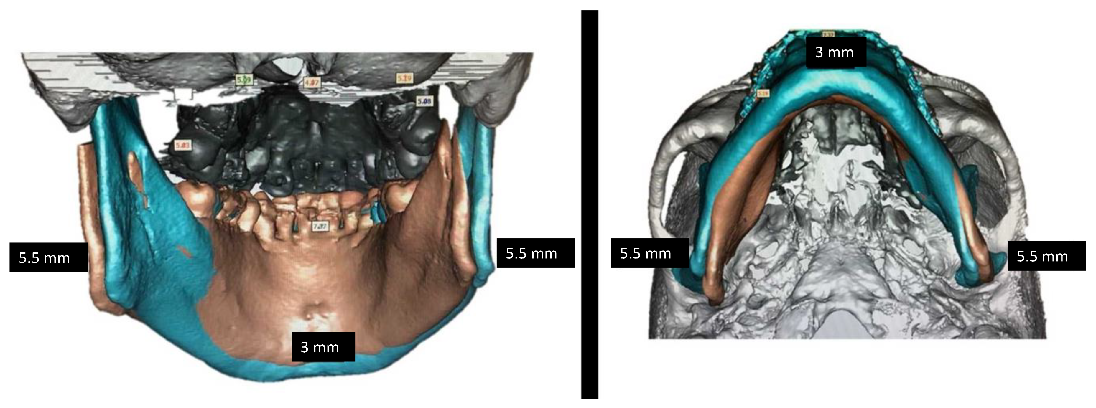
® 2P Articulator) and CT-based virtual planning (
Figure 8—SimPlant O&O, Lueven, Belgium).
As evident in
Figure 7, the model surgery revealed correct chin correction but rather a too limited angular movement (only 2 mm). On the contrary, the same surgical movement simulated on the PC demonstrated a larger angular movement that ensured complete correction of mandibular angles (
Figure 8).
In this particular case, the distance between the molars and angles was 34.8 mm dx. And 34.2 mm. sx. The mandible underwent setback and horizontal rotation, and the decided rotational amount was 6 degrees.
At the distance of 34.8 and 34.2 mm, 6 deg. rotation produces a difference of 3.48 and 3.42 (sin 6° = 0.10) between molars and angles transversal repositioning (
Figure 8 and
Figure 9). It is evident how, for the same rotational amount, there would appear to be almost no correction of the angles at the molar level (model surgery), while at the level of the angular bony regions (3D reconstruction) the correction is evident.
The patient was planned based on the CT reconstruction. In
Figure 10, the post-operatory aspect of the face shows, as well as a slight weight loss, not only a pleasant profile but also a complete correction both of the chin and angular symmetry. The case is almost finished orthodontically, and the dental occlusion is in course of final correction (
Figure 11).
4. Discussion
Nowadays, it is necessary for the surgeon to plan the facial aesthetics of his patients very carefully, because it is usually the first patient’s concern. Almost all patients who are to undergo orthognathic surgery present some degree of facial asymmetry [
9]. Even in cases of second- or third-class correction, it is uncommon that an asymmetric component is not also detected. The surgical correction of facial asymmetry is particularly complex because several parameters contribute to defining the symmetry of the face. A correct chin position and lateral projection of the mandibular angles contribute to generating a good final result [
11].
When planning the correction of the chin in space, it is necessary to ask the orthodontist for the correction of the lower dental midline in relation to the bony chin. When this orthodontic result is obtained and the case is planned on an articulator mounting, the dental midline is well representative of the bony chin since the two structures are very close to each other. This is not the case for the mandibular angle region; in fact, the lower molars are too far from the mandibular angles to represent their movement in space.
There are anatomical and clinical situations that may affect the distance between these two regions. The distance may be large when the whole mandible is large in class III patients, or when premolar extraction in the lower arch moves molar in a mesial direction. On the contrary, the distance is short in class II patients when the whole mandible is deficient and/or no extractions are planned in the lower arch. The larger the distance between the molar and the angle of the mandible, the greater the difference between the apparent movement of the angle on model surgery and the angle real movement.
Although the planning of orthognathic surgery is now mainly done with dedicated software, which allows the digital simulation of the osteotomy lines and movements of the maxillo-mandibular complex, it is equally true that not all healthcare structures are equipped with these technologies.
These structures continue to use model surgery, which in any case has a long history behind it [
20]. Centres that treat a limited number of dento-maxillofacial deformity cases often do not use 3D reconstruction software because of the high cost of these technologies and the long learning curve associated with them [
21]. The authors believe that the present study may contribute to the implementation of new 3D technologies in these structures as well.
The advantages that these software packages bring to everyday clinical practice are certainly several. They allow great precision in surgery planning and make it possible to carry out various plans on the same patient very quickly [
22]. They are also useful from a teaching point of view, as they as they have a great communicative impact on students and doctors in specialist training once they have learnt how to use them [
22].
The Authors’ research is therefore directed at both of these schools of work: in the case of using plaster models in the articulator, one must consider errors and risks in the analogue-only approach, as explained in the previous sections of this article; in the case of using three-dimensional software, on the other hand, this article further validates the accuracy of this digital workflow. For all these advantages, model surgery will certainly only be used in the future in limited cases, while only 3D technology will be used for routine surgery.
The present work adds further technical detail in support of this modern 3D technology.

