Article

Effect of Elastomeric Bearing Stiffness on the Dynamic Response of Railway Bridges Considering Vehicle–Bridge Interaction

Department of Civil Engineering and Energy Technology, Oslo Metropolitan University, 0176 Oslo, Norway
*
Author to whom correspondence should be addressed.
Appl. Sci. 2022, 12(23), 11952; https://doi.org/10.3390/app122311952
Submission received: 20 October 2022 / Revised: 17 November 2022 / Accepted: 18 November 2022 / Published: 23 November 2022
(This article belongs to the Special Issue Bridge Dynamics: Volume III)

Abstract

:
This article presents a numerical study that aims to explore the impacts of the stiffness of elastomeric bearings on the dynamic behavior of railway bridges under train-induced vibrations. For this purpose, a finite element code that considers vehicle–bridge interaction using a coupled approach was developed. The software was validated by comparing the numerical response to the analytical solution. The numerical analysis of single- and multi-span bridges with varying bearing stiffness values under passenger trains showed the interplay between bearing stiffness, its impact on the natural frequency of the bridge and the loading frequency. It is demonstrated that the amplitude of the maximum acceleration on the bridge depends heavily on the stiffness of the bearings. Furthermore, the bearing stiffness significantly impacts the location of the maximum acceleration on the bridge. The results of the extensive numerical analyses improve the understanding of the impact of the bearing stiffness on the dynamic behavior of bridges and highlight the importance of quantifying the boundary conditions correctly for reliable estimation of dynamic response of railway bridges under train-induced vibrations.

1. Introduction

Railway bridges are often seated on elastomeric bearings at the abutments and piers to prevent the contraction- and expansion-related stress concentrations. Bearings are also used in high-seismicity regions to protect buildings [1], their contents [2] and bridges. Despite their ubiquity in railway bridges, their impacts on the dynamic response of bridges are often neglected. Furthermore, the characteristics of the bearings are prone to significant variations during the lifetime of a bridge [3], which may significantly impact the dynamic response of the railway bridges.
The safety of the railway bridges is mainly governed by their dynamic response and fatigue life. Both the dynamic response and the fatigue life can be influenced significantly by the behavior of the bearings under train-induced vibrations. Unlike random loading on highway bridges, the train loading on railway bridges has a specific frequency spectrum that can significantly impact the bridge’s behavior [4]. This interaction has been studied extensively using a number of approaches of different complexities over the last few decades; e.g., [5,6,7]. Yang et al. [8] provide an excellent summary of different approaches for modeling the vehicle–bridge interaction. Using simpler models, several researchers investigated the behavior of bridges under train loading [9,10,11,12,13].
More complex models such as multi-body vehicle systems were also used in many cases. Cheng et al. [14] used a bridge–track–vehicle element which consists of vehicles modeled as mass-spring-damper systems and beam elements to model the rails and the bridge deck. Kwark et al. [15] idealized the problem and compared their solution to the moving load method numerically and using field tests. Majka and Hartnett [16] also utilized different modeling approaches to carry out a parametric analysis. In their study, vehicle damping was found to have a negligible influence on the bridge response. Zhang et al. [17] analyzed the dynamic behavior of a railway bridge and compared the results to the field measurements.
In another aspect, Refs. [18,19] investigated the vibration characteristics of the bridge–train system using a complex numerical model and field tests. Arguably, the most detailed parametric studies on this topic can be found in [20,21]. In both studies, the train–bridge interaction was modeled using both simple moving load models and more detailed interaction models. Impact of several parameters on the reduction in acceleration demands using detailed train bridge interaction models were evaluated and discussed. More recently, Gonzalez et al. [22] compared the suitability of uncoupled and coupled methods for solving vehicle–bridge interaction problems. Through numerical analysis of different vehicle and bridge parameters such as mass ratio and frequency ratio, Ref. [22] demonstrated the error introduced by the uncoupled method and how it increases with an increase in the vehicular dynamic force. These studies, similar to most of the others found in literature [9,15,17,18,19,23], are based on simply-supported beams and ignores the effect of the bearing stiffness on the vehicle–bridge interaction problem.
If the dynamic response of the bridge under moving train loads is sensitive to the bearing stiffness, deviations of these characteristics from the assumed values during the design phase may significantly alter the dynamic response of the bridge during its lifetime. Despite this potentially significant impact, few studies have focused on the interaction between the bearing stiffness and dynamic response. Arguably, Choi and Kim [24] and Yang et. al. [25] present the most detailed work on the subject. In this context, Yang et al. [25] examine the mechanisms of dynamic behaviour regarding resonance and cancellation when using elastic bearings. By implementing a moving load model with equal distance between each axle, a numerical study was conducted with verification from a field test. Although the use of elastic bearings for railway bridges have several benefits, Yang et al. [25] also bring attention to the prevention of transmitting the vehicle-induced vibrations to the ground. This may lead to the accumulation of induced vibrations which promotes greater fatigue of the bridge. Similar studies were also reported for single span beams in [26,27,28] while only a handful studies [29,30] focus on the impact of elastomeric bearings on the behavior of multi-span bridges.
Xu and Li [30] further investigated the effect of coupling conditions between different spans of multi-span bridges while using a moving load model. In a slightly different framework, Zangeneh et al. [31], by using viscoelastic supports for a simple beam, have developed a discrete model, which considers the soil–structure interaction effects on the modal properties of a beam.
Although a vast majority of the railway bridges rest on elastomeric bearings, most of the work that focuses on vehicle–bridge interaction so far is based on restrained boundary conditions. The few articles that consider the bearing stiffness [25,26,27,29,30,32] shed light into the impact of this parameter on the dynamic response of railway bridges. However, there is a need to systematically study the impact of the bearing stiffness on the dynamic response of railway bridges and vehicle–bridge interaction.
This article is an extension of an earlier study [33], which addresses this gap in literature. For this, a finite element code was developed in MATLAB that can simulate the vehicle–bridge interaction via a coupled model. The developed code was verified by comparing its results to the analytical solutions provided in literature. A numerical model of a 50 m long railway bridge is created in this software and its dynamic response under a passenger train crossing for various bearing stiffness values was computed. Two-span and three-span variations of the benchmark bridge were then created and the response analysis was repeated to be able study the impact of the bearing stiffness on the dynamic response of the multi-span bridges. By introducing intermediate supports to create the two- and three-span bridges, the interplay between the vibrations in the different spans was studied. Furthermore, the differences in the effect of the elastomeric bearings located at the edges and in the middle supports were evaluated. Finally, introducing the two- and three-span bridges created variations in the natural frequencies of the bridge so that a wider frequency range could be covered by the study.
The article is structured in the following way: First, the theoretical foundation of the developed finite element code is summarized. The developed code was validated by comparing its results with analytical response of a simply-supported beam under a single sprung mass. A simply-supported, 50 m long prestressed concrete railway bridge was selected as the benchmark case and introduced next. Two-span and three-span variations of the benchmark bridge were then introduced, and the numerical analysis conducted on the three bridges was evaluated to study the impact of bearing stiffness on the dynamic response of single- and multi-span bridges. Finally, the conclusions drawn from the conducted analysis are summarized, and needs for future research are discussed.

2. Theoretical Background

A finite element software was developed in MATLAB [34] computational environment to facilitate the automation of the significant number of numerical analysis conducted for the parametric study. Finite element models are well-suited for the complex vehicle–bridge-interaction (VBI) problem as they can reproduce the geometry of the vehicle and the bridge while considering other parameters such as bearing stiffness and their impact on the VBI. In this study, the bridge is modeled using a series of Euler–Bernoulli beams discretized at several points while the train is modeled as a series of masses connected to a spring and dashpot, which simulate the stiffness and the damping characteristics of the suspension systems of the train, respectively.
Once the stiffness, mass and damping matrices of the bridge and the vehicle are defined, the equations of motion for each subsystem, i.e., the bridge and the vehicle, can be written as:
[ M b ] { u ¨ b } + [ C b ] { u ˙ b } + [ K b ] { u b } = { F b }
[ M v ] { u ¨ v } + [ C v ] { u ˙ v } + [ K v ] { u v } = { F v }
where [ M j ] , [ C j ] , and [ K j ] are the mass, damping, and stiffness matrices, respectively; F j are the time variant forces, and { u ¨ j } , { u ˙ j } , { u j } are the acceleration, velocity, and displacement, respectively. Sub-indices j = b and j = v refer to the bridge and vehicle, respectively.
The equations of motion for the bridge and vehicle given in Equations (1) and (2), respectively, can be solved using either coupled or uncoupled approach. In the uncoupled approach, Equations (1) and (2) for each sub-system are solved separately. The compatibility of the forces and the displacements between the vehicle and the bridge is ensured through an iterative process at each time step. Although the uncoupled approach provides an attractive alternative as it avoids numerical instabilities due to singularities in the time-varying stiffness and damping matrices associated with the coupled approach, it implicitly assumes that the effect of the time-varying properties of the VBI system on the dynamic features of the response is negligible compared to that of the bridge, i.e., the frequencies and mode shapes of the bridge are invariant with time [22]. Although this assumption can be reasonable for vehicles with mass negligible compared to the mass of the bridge, it may lead to inaccuracies when the vehicle mass is significant enough to alter the vibration frequencies and the mode shapes of the bridge [22]. Considering the relatively high mass of trains and their impact on the vibration frequencies of railway bridges [35,36,37], it was decided to use the coupled approach to solve the system of equations.
In the coupled approach, the system of equations of motions of the bridge (Equation (1)) and the vehicle (Equation (2)) are combined and solved using accurate and efficient numerical integration methods [38] that are suitable for second-order ordinary differential equations. The mass, damping and stiffness matrices of the bridge and the vehicle are combined to create global mass, damping and stiffness matrices, respectively. If the interaction forces due to track irregularities are ignored, the equation of motion for the entire system can be written as:
M b 0 0 M v u ¨ b u ¨ v + C b C b v C v b C v u ˙ b u ˙ v + K b K b v K v b K v u b u v = 0 M v g
where the mass matrix and the force vector are time-invariant while the stiffness and damping matrices are time-variant, and g is acceleration of gravity. More specifically, the stiffness matrix, K, is time variant and, along with the time variant damping matrix, mathematically consider the interaction between the vehicle and the bridge. As an example, the stiffness matrix when the spring mass is located on the vertical degree of freedom i of the discretized bridge model can be written as:
K b K v b K b v K v = k 1 , 1 k 1 , 2 k 1 , i k 1 , n 1 k 1 , n 0 k 2 , 1 k 2 , 2 k 2 , i k 2 , n 1 k 2 , n 0 k i 1 , 1 k i 1 , 2 k i 1 , i k i 1 , n 1 k i 1 , n 0 k i , 1 k i , 2 k i , i + k v k i , n 1 k i , n k v k i + 1 , 1 k i + 1 , 2 k i + 1 , i k i + 1 , n 1 k i + 1 , n 0 k n 1 , 1 k n 1 , 2 k n 1 , i k n 1 , n 1 k n 1 , n 0 k n , 1 k n , 2 k n , i k n , n 1 k n , n 0 0 0 k v 0 0 k v
where k i , j are the elements of the stiffness matrix of the bridge and k v is the stiffness of the vehicle. When the vehicle is represented using a single-degree-of-freedom system, the submatrices K v b and K b v are 1 x N and N x 1 vectors, respectively, where N is the number of degrees of freedom on the bridge. When the vehicle is represented using a multi-degree of freedom system with N v degrees of freedom, the submatrices K v b and K b v are N v x N and N x N v vectors, respectively. In Equation (4), the interaction between the vehicle and the bridge is achieved through the i t h elements of the K v b and K b v vectors as well as the diagonal term in K b = k i , i + k v .
Using Rayleigh damping, a similar equation to Equation (4) can be written for the damping matrix as it is a combination of the time-invariant mass matrix and the time-variant stiffness matrix. As such, the vehicle–bridge interaction is achieved through time-variant stiffness and damping matrices.
The developed FE software is based on the theoretical background summarized above and elsewhere [22]. As the next step, the developed FE software is validated by computing the response of an undamped simply-supported beam under a single sprung mass that was initially presented by [39] and used in several studies such as [8,16]. Figure 1 presents the modeling parameters of the sprung mass and the bridge used in the verification of the developed software.
The acceleration and displacement response of the bridge and the sprung mass was computed using the developed software, and the results are compared with the solution presented by Yang et al. [8] as well as the analytical solution obtained considering the first mode response only. The results depicted in Figure 2 show that the developed software can capture the acceleration and displacement response of the bridge under moving sprung mass.
The bridge stiffness matrix, K b , can be modified to include the stiffness of the bearings leading to the numerical model depicted in Figure 3. In this model, each moving axle consists of a mass, a spring and a dashpot, which simulate the inertia, stiffness and the damping characteristics of the vehicle, respectively. While the interaction between each axle and the bridge is considered, pitching and rolling of the train cannot be considered with the developed model.

3. Numerical Analysis

To investigate the impact of the bearing stiffness on the dynamic response of railway bridges, numerical analyses were conducted on three separate bridges, one single-span and two multi-span, under train loading. The single-span bridge used is a 50 m long railway bridge. Young´s Modulus of concrete was taken as 32 GPa, and the moment of inertia of the cross-section about the main bending axis is 16.89 m4. The mass per unit length is assumed to be 22.9 t/m including the track bed and the ballast and modeled as lumped mass at each node. Damping is modeled as 2% Rayleigh damping anchored at the first and third mode frequencies. The bridge is discretized at equal distances of 0.025 m. The horizontal movement in the supports is restrained considering their negligible effect while the ends of the bridge are free to rotate. Elastic springs with a stiffness of k v , which varied between 1 × 10 4 kN/m and 1 × 10 15 kN/m, is used to simulate the vertical behavior of elastomeric bearings. Here, it should be noted that, for most of the commercially available elastomeric bearings, the stiffness varies between 1 × 10 5 kN/m and 1 × 10 7 kN/m, but a wider range was used in this study to consider possible variation in the bearing stiffness due to factors such as aging and deterioration. Stiffer values were considered to simulate the fully restrained case, which is commonly used in literature as well as to account for possible stiffening in bearings with aging.
Two- and three-span bridges were created from the single span bridge by introducing elastomeric bearings at the column locations. The cross-sectional properties and the length of the bridge was kept constant. Figure 4 depicts the overview of the two- and three-span bridges generated from the single-span bridge. The multi-span bridges used in the study represent a very common bridge type, where elastomeric bearings are placed at the top of the columns while the bridge deck is continuous throughout the entire bridge length. Introducing the middle supports serves two main purposes: (i) the frequency of the bridge is altered significantly, and thus the dynamic analysis is repeated for a new set of bridge frequencies paving the way to evaluate the effect of the bridge frequency and its interplay with the loading frequency on the dynamic response of the bridge, and (ii) the difference in the behavior of the end and middle spans can be evaluated.
As the train model, without losing generality, the ICE-2 train is selected as a representative of modern passenger trains. The configuration and the axle distances for a typical ICE-2 train are depicted in Figure 5. The axle load, suspension stiffness and suspension damping used in the numerical analysis are 19.995 t, 4800 kN/m and 109 kNs/m, respectively. It should be noted that, although only one type of train, ICE-2, is used in this study, the properties of the ICE-2 train are similar to other trains such as TGV [40], and the results presented in this article can be generalized for modern passenger trains. For each bridge and bearing stiffness configuration, dynamic analyses were repeated for speeds of 50 km/h, 80 km/h and 130 km/h. Figure 6 shows the Fourier Amplitude Spectrum (FAS) of the loading function of the ICE-2 train for the relevant speeds.
The track irregularities are not considered in the study because the main focus of the article is to evaluate the impact of the bearing stiffness on the frequency content and bending behavior of the bridge. Although the amplitudes of vibrations are used in the article to identify the resonance conditions, prediction of the acceleration amplitudes is out of the scope of this article. For this reason, only the vibrations that are created by the bending behavior of the bridge are considered and not by other sources such as track irregularities.

3.1. Single-Span Bridge

Figure 7 presents the natural frequencies of the bridge for different bearing stiffness values. This plot indicates that the vertical motion at the supports can be assumed to be restrained once the vertical stiffness of the bearing exceeds 1 × 10 8 kN/m as the natural frequencies of the bridge remains unchanged beyond this threshold value. Figure 7 shows that the frequencies of the bridge start to change significantly when k v < 1 × 10 7 kN/m.
Next, elastic response history analyses were conducted to investigate the effect of the bearing stiffness on the dynamic response of the bridge. Figure 8 presents the absolute maximum accelerations computed at nodes discretized at one meter for varying bearing stiffness and train speeds. Maximum acceleration is selected as the main response parameter because it is the main parameter that impacts the ballast stability and, therefore, is arguably the most important criterion for the serviceability of the railway bridges.
The maximum accelerations at the mid-span are shown to be very sensitive to the bearing stiffness. Meanwhile, the maximum acceleration values remain virtually constant at the mid-span for k v 1 × 10 8 kN/m, and they start to increase significantly as the bearing stiffness drops below this threshold value.
The variation in the maximum acceleration demands at the mid-span with bearing stiffness can be explained relatively simply with the effect of the latter on the vibration frequencies for k v 1 × 10 6 kN/m as depicted in Figure 7. For bearing stiffness values under this threshold, the vibration frequencies decrease significantly compared to the virtually rigid cases leading to an increase in the acceleration amplitudes. However, it is difficult to use the same argument to explain the increase in the accelerations for k v = 1 × 10 7 kN/m. For this bearing stiffness value, the vibration frequencies computed from an eigenvalue analysis remain virtually identical compared to those for k v 1 × 10 8 kN/m. On the other hand, the maximum accelerations increase significantly compared to the stiffer cases. For example, even at the mid-span, the maximum accelerations reach 0.9 m/s 2 for k v = 1 × 10 7 kN/m for a train speed of 80 km/h compared to 0.0 5 m/s 2 for k v = 1 × 10 15 kN/m.
To understand the reason behind this discrepancy, the Fourier Amplitude Spectra (FAS) of the acceleration time histories at the mid-span for different bearing stiffness values were plotted in Figure 9. The FAS for bearing stiffness values of k v 1 × 10 8 kN/m indicate that the behavior of the bridge is dominated by the first mode at f < 5 Hz although some influence of the third mode around 25 Hz is also visible. On the other hand, the third mode becomes the dominant mode for k v = 1 × 10 7 kN/m with very little energy at frequencies f < 5 Hz compared to the higher bearing stiffness values. A closer look at Figure 7 shows that, although the frequencies of the first two modes remain virtually identical when the bearing stiffness is reduced to k v = 1 × 10 7 kN/m, the third mode frequency drops from 27.5 Hz for k v 1 × 10 8 kN/m to 25.2 Hz for k v = 1 × 10 7 kN/m. The Fourier Amplitude Spectrum of the loading for 80 km/h depicted in Figure 6b indicate that the decrease in the third mode frequency for k v = 1 × 10 7 kN/m leads to a resonance condition between the loading and the bridge at around 25–26 Hz leading to a significant increase in the contribution of the third mode for this bearing stiffness. In addition, Figure 9 indicates that the fourth mode with a frequency around 45 Hz also contributes significantly to the acceleration response. Similar to the third mode, the fourth mode comes into a resonance condition with the loading frequency (see Figure 6b) and thus contributes significantly to the response. Therefore, the change in bearing stiffness can significantly affect the dynamic response of the bridge even its impact on the modal frequencies is small because it leads to a change in the predominant mode of vibration.
A similar behavior can also observed for the bearing stiffness value of k v = 1 × 10 6 kN/m. Figure 9 shows that the behavior of the bridge is dominated by the frequencies 15 Hz and 36 Hz for k v = 1 × 10 6 kN/m. These correspond to the third and fourth vibration modes of the bridge, respectively, and are very close to the dominant loading frequencies as indicated by the loading function for a speed of 80 km/h; see Figure 6b.
When the bearing stiffness value is reduced further to k v = 1 × 10 5 kN/m and 1 × 10 4 kN/m, the dynamic response of the bridge continues to be dominated by third mode of the bridge, which has a frequency between 7 and 8 Hz, while the influence of the fourth mode diminishes.
The results summarized above indicate the sensitivity of the dynamic response and the dominant mode to the bearing stiffness. Furthermore, the bearing stiffness has a significant influence on the location of the maximum accelerations. While the maximum acceleration is closer to the mid-span for the case of k v = 1 × 10 15 kN/m, its location shifts towards the ends of the bridge as the bearing stiffness gets lowered. Here, it should be noted that some sudden jumps were observed at the ends of the bridge for 1 × 10 8 kN/m k v 1 × 10 10 kN/m. A possible explanation for these sudden jumps can be the singularities associated with the Finite Element Method at the boundaries. Since the bridge is modeled as a stand-alone structure without the front and back approaches, the train movement starts and ends abruptly at the two supports which may lead the inaccuracies at the edges depicted in Figure 8. Although the acceleration values at the support for 1 × 10 8 kN/m k v 1 × 10 10 kN/m may not be exact, it is clear from Figure 8 that the location of the maximum accelerations shifts towards the edges for k v 1 × 10 9 kN/m.
This shift in the location of the maximum acceleration can be explained by the impact of the bearing stiffness on the mode shape of the bridge as it modifies the boundary conditions of the bridge. As an example, the first and third mode shapes for different bearing stiffness values are plotted in Figure 10. While the first mode shape remains identical for the two cases, there is a significant difference in the third mode shape, particularly at the bearing locations for k v = 1 × 10 10 kN/m and k v = 1 × 10 7 kN/m. The modal displacements at the bearing location increase even further when the bearing stiffness is reduced further. Recalling that the third mode begins to dominate the dynamic response of the bridge for k v 1 × 10 7 kN/m, the increase in the modal displacement close to the abutments for these bearing stiffness values for the third mode can be indicated as the reason why the location of the absolute maximum acceleration on the bridge shifts from the mid-span towards the ends of the bridge with a decrease in the bearing stiffness.

3.2. Multi-Span Bridges

As the next step, the numerical study was repeated for the two- and three-span bridges. Figure 11 presents the variation of the natural vibration frequencies of the two-span bridge for the first vertical modes. As expected, the two-span bridge has higher frequencies for each mode compared to its single-span counterpart (Figure 7). Similar to the single-span bridge, vibration frequencies of the first two modes of the two-span bridge remain relatively identical for k v 1 × 10 8 kN/m while a significant drop can be observed in the third and higher mode frequencies when the bearing stiffness is k v = 1 × 10 8 kN/m and continue to drop as the bearing stiffness continues to reduce.
Figure 12 presents the maximum accelerations at different locations of a two-span bridge for different bearing stiffness values and train speeds of 50, 80, and 130 km/h, respectively. The results for the two-span bridge are similar to those obtained for a single-span bridge that are presented in Figure 8 in many aspects. For example, the location of the absolute maximum acceleration along the length of the bridge shifts from the middle of the span to the ends of the bridge. However, the accelerations at the middle support remain the lowest along the length of the bridge for all the bearing stiffness values investigated. For k v 1 × 10 9 kN/m, the bearings remain virtually rigid, and the vibrations are minimal although the shift in the location of maximum acceleration location can already be observed for k v = 1 × 10 9 kN/m. As the bearing stiffness decreases, the accelerations at the middle support increase but remain less than those at the other locations of the bridge. This is unlike the supports at either end of the bridge, which become the point of highest acceleration for lower bearing stiffness values. This difference can be explained by the discrepancy in the boundary conditions for these locations. The train traverses the relatively soft bridge before arriving at the middle support and after leaving it. As such, the vibrations at the middle support are dominated by the bridge stiffness and frequency. On the contrary, the train travels over an infinitely rigid surface before crossing the bearing, which is stiffer compared to the bridge itself even for the lower bearing stiffness values. Only after traveling some meters, the stiffness and the frequency of the bridge start to dominate the behavior. Therefore, the vibrations close to the end bearings are dominated by high frequency motion that leads to higher acceleration amplitudes compared to the bearing at the middle.
To further study the impact of the bearing stiffness on the frequency content of the dynamic response, Fourier Amplitude Spectrum of the acceleration response at the middle of the first span was created and presented in Figure 13 for speeds of 50 km/h and 80 km/h. For both speeds, the sensitivity of the frequency content of the vibrations to the bearing stiffness is evident. Particularly for the speed of 50 km/h, the vibrations are dominated by the first mode for k v = 1 × 10 4 kN/m and k v = 1 × 10 5 kN/m; see Figure 13a. For the higher bearing stiffness values, k v 1 × 10 8 kN/m, the effect of the second mode at approximately 20 Hz is evident from Figure 13a. The most complicated behavior as far as frequency content is concerned can be observed for k v = 1 × 10 6 kN/m and k v = 1 × 10 7 kN/m. For the former, the behavior is dominated by the first mode, but the contributions of the third and fourth modes at approximately 25 Hz and 40 Hz are not negligible.
For the speed of 80 k m / h (Figure 13b), for higher bearing stiffness values of k v 1 × 10 8 kN/m, the contribution of the second mode becomes more prominent. Furthermore, the second and third modes contribute much more to the dynamic response for k v = 1 × 10 4 kN/m and k v = 1 × 10 5 kN/m. Nonetheless, the first mode dominates the behavior compared to the higher bearing stiffness values.
Finally, the numerical analysis was repeated for the three span bridge shown in Figure 4. This bridge has much higher natural vibration frequencies compared to the single- and two-span bridges as depicted in Figure 14. However, similar observations regarding the variation of the natural frequencies can be made as the frequencies tend to remain constant for k v 1 × 10 8 kN/m while decreasing significantly when the bearing stiffness drops below this value. The change in the frequencies is especially sharp between 1 × 10 6 kN/m k v 1 × 10 8 kN/m.
The variation of maximum accelerations along the length of the bridge shown in Figure 15 is also similar to those observed for single-span and two-span bridges. Firstly, the maximum accelerations increase with a decrease in the bearing stiffness. Furthermore, the location of the maximum acceleration shifts from the middle of the spans towards the ends of the bridge. The accelerations at the middle supports tend to remain to be lower than the other parts of the bridge.
Finally, Figure 16 shows the Fourier amplitude spectrum of the accelerations computed at the middle of the second span for the three-span bridge for speeds of 50 km/h and 80 km/h. Comparing the FAS for 50 km/h in Figure 16a and for 80 km/h in Figure 16b reveals the impact of the train speed on the frequency content of the bridge vibrations. For the higher bearing stiffness values, the first mode is dominant for the 50 km/h, while higher modes become more active for lower stiffness values. When the train speed is increased to 80 km/h, the second mode becomes the dominant mode of vibration for higher bearing stiffness values as well. On the other hand, for this train speed and k v = 1 × 10 4 kN/m, the vibrations are dominated solely by the first mode of vibration.
Figure 9, Figure 13, and Figure 16 show the complex relationship between the frequency content of the vibrations and the bearing stiffness for bridges with both relatively low (single-span) and high (multi-span) natural frequencies. Thus, variations in the bearing stiffness throughout the lifetime of the structure can lead to significant variations in its dynamic response under train loading. Furthermore, the results also indicate the importance of accurately modeling the bearing stiffness in the evaluation of the bridge under service loading. Considering the uncertainties in the production stage that may lead to deviations from the prescribed bearing stiffness values such as partial loss of contact between the bearing and concrete surfaces through stochastic analysis can be necessary in certain cases where the response parameters are close to the threshold values.

4. Conclusions

The aging of the railway bridge infrastructure and the modernization of the train fleets worldwide necessitates regular safety assessment of railway bridges. Vital in this assessment procedure is the vehicle–bridge interaction and the ability of the numerical models to reflect the dynamic properties of the vehicles and bridges. Although elastomeric bearings are ubiquitous in railway bridges, research that quantifies their effect on the bridge response is scarce. This study, which aims to understand and quantify the effect of bearing stiffness on the dynamic response of railway bridges, is motivated by this scarcity.
A finite element code that can take vehicle–bridge interaction into account is developed to analyze the behavior of railway bridges with varying bearing stiffness values. The code is then verified using the existing literature. The developed code conducts the vehicle–bridge interaction analysis at a relatively low computational cost compared to commercially available software paving the way to the parametric study reported in this article.
Single- and multi-span bridges with varying bearing stiffness values were modeled using the developed software, and their dynamic response under vibrations induced by passenger trains traveling with different speeds was computed. As a result of the numerical analysis conducted, the following conclusions can be drawn.
  • The bearing stiffness has a significant influence on the dynamic response on railway bridges at all train speeds considered in the study. Not only the amplitudes of the accelerations varied with the changes in the train speed but also the locations of the maximum accelerations shifted considerably.
  • The vertical stiffness of the bearings can be assumed to be infinite when its value exceeds 1 × 10 8 kN/m as neither the bridge frequency nor the acceleration response of the bridge is affected once the vertical bearing stiffness exceeds this value.
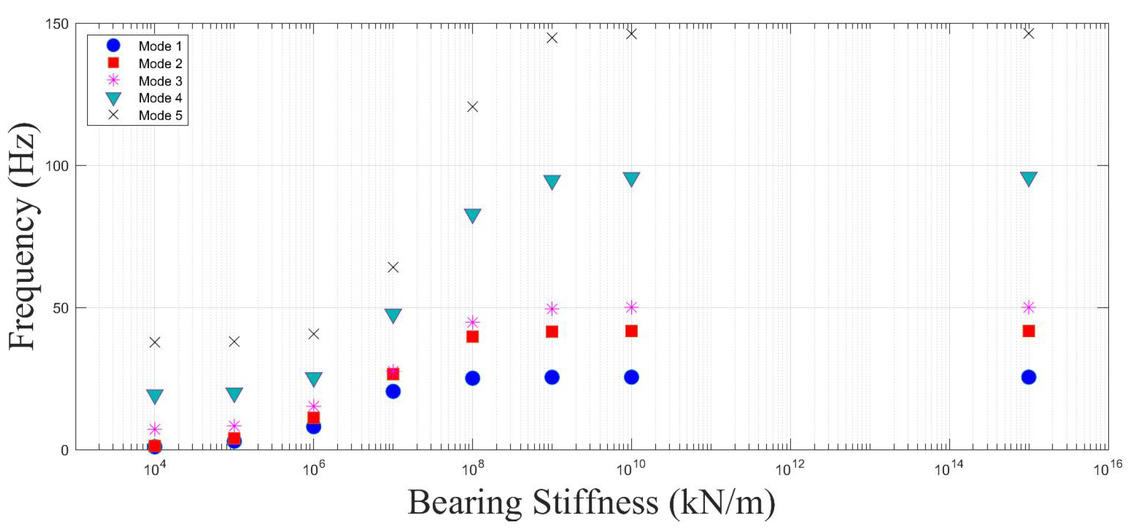
  • Even when the first and second mode frequencies of the bridge is not affected by the variations in the bearing stiffness, the subtle change in the higher mode frequencies can lead to significant changes in the acceleration response. For the single-span bridge analysed, only the third mode frequency of the bridge was slightly changed when the bearing stiffness was reduced from 1 × 10 8 kN/m to 1 × 10 7 kN/m while the frequencies of the first two modes remained the same. However, this subtle change combined with the change in the third vertical mode shape led to a significant increase in the acceleration response as well as in a shift in the location of the maximum acceleration.
  • For the multi-span bridges, the bearings at the ends of the bridge and the middle supports have a significantly different impact. When all bearings are infinitely rigid, the accelerations at each of the bearings are naturally zero. As the bearing stiffness is decreased, the accelerations at the end bearing increase rapidly, and the maximum accelerations are recorded at these edges. On the other hand, the accelerations over the middle bearings remain the lowest values over the entire bridge for all the bearing stiffness values considered.
  • The acceleration response of the bridges was not significantly influenced by the train speed for the speeds considered in this study when the bearing stiffness is lower than 1 × 10 8 kN/m. The effect of train speed in acceleration response is more pronounced for higher bearing stiffness values.
  • For certain bearing stiffness values, the finite element analysis can suffer from instabilities at the boundaries, and the results for these cases should be evaluated carefully. However, once the bearing stiffness values drop below 1 × 10 7 kN/m, these instabilities disappear. Modeling the front and back approaches can solve these instabilities and will be included in further research.
This study contributes to understanding the dynamic behavior of railway bridges under various bearing stiffness values. The outcomes of this study demonstrates the importance of accurately modeling the bearing stiffness in the analysis, especially when it drops below the threshold value of 1 × 10 8 kN/m.
The study is limited to a single bridge deck and train geometry and three train speeds. Further research is necessary to take into account the energy dissipation capabilities of elastomeric bearings and to expand the observations made in this study to different train geometries and train speeds.

Author Contributions

Conceptualization, E.E. and S.G.; methodology, E.E., C.N. and S.G.; software, E.E. and C.N.; validation, C.N.; formal analysis, C.N.; writing—original draft preparation, E.E.; writing—review and editing, S.G.; visualization, C.N. and S.G.; supervision, E.E. and S.G. All authors have read and agreed to the published version of the manuscript.

Funding

This research received no external funding.

Data Availability Statement

The data generated through numerical simulations are available upon request.

Conflicts of Interest

The authors declare no conflict of interest.

References

  1. Vaiana, N.; Sessa, S.; Paradiso, M.; Marmo, F.; Rosati, L. An efficient computational strategy for nonlinear time history analysis of seismically base-isolated structures. In Proceedings of the XXIV AIMETA Conference 2019, Rome, Italy, 15–19 September 2019; pp. 1340–1353. [Google Scholar] [CrossRef]
  2. Pellecchia, D.; Feudo, S.L.; Vaiana, N.; Dion, J.L.; Rosati, L. A procedure to model and design elastomeric-based isolation systems for the seismic protection of rocking art objects. Comput.-Aided Civ. Infrastruct. Eng. 2022, 37, 1298–1315. [Google Scholar] [CrossRef]
  3. Natale, A.; Vecchio, C.D.; Ludovico, M.D.; Caner, A.; Naghshineh, A.K.; Jacak, M. Creep effects on elastomeric and ball rubber bearings under sustained lateral loads. Struct. Infrastruct. Eng. 2022, 1–11. [Google Scholar] [CrossRef]
  4. Gonen, S.; Demirlioglu, K.; Erduran, E. Modal Identification of a Railway Bridge Under Train Crossings: A Comparative Study. In Dynamics of Civil Structures; Springer: Cham, Switzerland, 2022; pp. 33–40. [Google Scholar] [CrossRef]
  5. Ichikawa, M.; Miyakawa, Y.; Matsuda, A. Vibration analysis of the continuous beam subjected to a moving mass. J. Sound Vib. 2000, 230, 493–506. [Google Scholar] [CrossRef]
  6. Frýba, L. Vibration of Solids and Structures under Moving Loads; Springer: Berlin/Heidelberg, Germany, 1999. [Google Scholar] [CrossRef]
  7. Michaltsos, G.; Sophianopoulos, D.; Kounadis, A.N. The effect of a moving mass and other parameters on the dynamic response of a simply supported beam. J. Sound Vib. 1996, 191, 357–362. [Google Scholar] [CrossRef]
  8. Yang, Y.B.; Yau, J.; Yao, Z.; Wu, Y. Vehicle-Bridge Interaction Dynamics: With Applications to High-Speed Railways; World Scientific: Singapore, 2004. [Google Scholar]
  9. Garinei, A.; Risitano, G. Vibrations of railway bridges for high speed trains under moving loads varying in time. Eng. Struct. 2008, 30, 724–732. [Google Scholar] [CrossRef]
  10. Yang, Y.B.; Lin, C.W. Vehicle-bridge interaction dynamics and potential applications. J. Sound Vib. 2005, 284, 205–226. [Google Scholar] [CrossRef]
  11. Xia, H.; Zhang, N.; Guo, W. Analysis of resonance mechanism and conditions of train–bridge system. J. Sound Vib. 2006, 297, 810–822. [Google Scholar] [CrossRef]
  12. Lu, Y.; Mao, L.; Woodward, P. Frequency characteristics of railway bridge response to moving trains with consideration of train mass. Eng. Struct. 2012, 42, 9–22. [Google Scholar] [CrossRef]
  13. Jin, Z.; Li, G.; Pei, S.; Liu, H. Vehicle-induced random vibration of railway bridges: A spectral approach. Int. J. Rail Transp. 2017, 5, 191–212. [Google Scholar] [CrossRef] [Green Version]
  14. Cheng, Y.S.; Au, F.T.; Cheung, Y.K. Vibration of railway bridges under a moving train by using bridge-track-vehicle element. Eng. Struct. 2001, 23, 1597–1606. [Google Scholar] [CrossRef]
  15. Kwark, J.W.; Choi, E.S.; Kim, Y.J.; Kim, B.S.; Kim, S.I. Dynamic behavior of two-span continuous concrete bridges under moving high-speed train. Comput. Struct. 2004, 82, 463–474. [Google Scholar] [CrossRef]
  16. Majka, M.; Hartnett, M. Effects of speed, load and damping on the dynamic response of railway bridges and vehicles. Comput. Struct. 2008, 86, 556–572. [Google Scholar] [CrossRef]
  17. Xia, H.; Zhang, N. Dynamic analysis of railway bridge under high-speed trains. Comput. Struct. 2005, 83, 1891–1901. [Google Scholar] [CrossRef]
  18. Ju, S.H.; Lin, H.T. Resonance characteristics of high-speed trains passing simply supported bridges. J. Sound Vib. 2003, 267, 1127–1141. [Google Scholar] [CrossRef]
  19. Ju, S.H.; Lin, H.T.; Huang, J.Y. Dominant frequencies of train-induced vibrations. J. Sound Vib. 2009, 319, 247–259. [Google Scholar] [CrossRef]
  20. Arvidsson, T.; Karoumi, R. Train–bridge interaction – a review and discussion of key model parameters. Int. J. Rail Transp. 2014, 2, 147–186. [Google Scholar] [CrossRef]
  21. Doménech, A.; Museros, P.; Martínez-Rodrigo, M.D. Influence of the vehicle model on the prediction of the maximum bending response of simply-supported bridges under high-speed railway traffic. Eng. Struct. 2014, 72, 123–139. [Google Scholar] [CrossRef]
  22. González, A.; Covián, E.; Casero, M. Verifying the suitability of uncoupled numerical methods for solving vehicle–bridge interaction problems. Struct. Infrastruct. Eng. 2022, 1–18. [Google Scholar] [CrossRef]
  23. Liu, K.; De Roeck, G.; Lombaert, G. The effect of dynamic train-bridge interaction on the bridge response during a train passage. J. Sound Vib. 2009, 325, 240–251. [Google Scholar] [CrossRef]
  24. Choi, J.Y.; Kim, S.H. Impact Evaluation of Track Girder Bearing on Yeongjong Grand Bridge. Appl. Sci. 2020, 10, 68. [Google Scholar] [CrossRef] [Green Version]
  25. Yang, Y.; Lin, C.; Yau, J.; Chang, D. Mechanism of resonance and cancellation for train-induced vibrations on bridges with elastic bearings. J. Sound Vib. 2004, 269, 345–360. [Google Scholar] [CrossRef]
  26. Yau, J.; Wu, Y.; Yang, Y. Impact Response of Bridges with Elastic Bearings to Moving Loads. J. Sound Vib. 2001, 248, 9–30. [Google Scholar] [CrossRef]
  27. Zhang, Z.; Li, X.Z.; Zhang, X.; Liu, Q. Study on the vibration-isolation effects of elastic bearings on train-induced vibration of railway bridge. Eng. Mech. 2015, 32, 103. [Google Scholar] [CrossRef]
  28. Zhu, X.; Law, S. Moving load identification on multi-span continuous bridges with elastic bearings. Mech. Syst. Signal Process. 2006, 20, 1759–1782. [Google Scholar] [CrossRef]
  29. Kim, C.W.; Kawatani, M.; Hwang, W.S. Reduction of traffic-induced vibration of two-girder steel bridge seated on elastomeric bearings. Eng. Struct. 2004, 26, 2185–2195. [Google Scholar] [CrossRef] [Green Version]
  30. Xu, H.; Li, W.L. Dynamic behavior of multi-span bridges under moving loads with focusing on the effect of the coupling conditions between spans. J. Sound Vib. 2008, 312, 736–753. [Google Scholar] [CrossRef]
  31. Zangeneh, A.; Battini, J.M.; Pacoste, C.; Karoumi, R. Fundamental modal properties of simply supported railway bridges considering soil-structure interaction effects. Soil Dyn. Earthq. Eng. 2019, 121, 212–218. [Google Scholar] [CrossRef]
  32. Zhu, Z.; Wang, L.; Yu, Z.; Gong, W.; Bai, Y. Non-Stationary Random Vibration Analysis of Railway Bridges under Moving Heavy-Haul Trains. Int. J. Struct. Stab. Dyn. 2018, 18, 1–21. [Google Scholar] [CrossRef]
  33. Erduran, E.; Nordli, C.; Salehi, M.; Gonen, S. Effect of Aging of Bearings on the Behavior of Single-Span Railway Bridges. In European Workshop on Structural Health Monitoring; Springer: Berlin/Heidelberg, Germany, 2022; pp. 680–688. [Google Scholar] [CrossRef]
  34. MATLAB. Version 9.10.0 (R2021a); The MathWorks Inc.: Natick, MA, USA, 2021. [Google Scholar]
  35. Erduran, E.; Gonen, S.; Alkanany, A. Parametric analysis of the dynamic response of railway bridges due to vibrations induced by heavy-haul trains. Struct. Infrastruct. Eng. 2022, 1–14. [Google Scholar] [CrossRef]
  36. Salehi, M.; Demirlioglu, K.; Erduran, E. Evaluation of the effect of operational modal analysis algorithms on identified modal parameters of railway bridges. In Proceedings of the IABSE Congress, Ghent—Structural Engineering for Future Societal Needs, Ghent, Belgium, 22–24 September 2021. [Google Scholar]
  37. Salehi, M.; Erduran, E. Identification of boundary conditions of railway bridges using artificial neural networks. J. Civ. Struct. Health Monit. 2022, 12, 1223–1246. [Google Scholar] [CrossRef]
  38. Vaiana, N.; Sessa, S.; Marmo, F.; Rosati, L. Nonlinear dynamic analysis of hysteretic mechanical systems by combining a novel rate-independent model and an explicit time integration method. Nonlinear Dyn. 2019, 98, 2879–2901. [Google Scholar] [CrossRef]
  39. Biggs, J.M.; Biggs, J. Introduction to Structural Dynamics; McGraw-Hill: New York, NY, USA, 1964. [Google Scholar]
  40. Glatz, B.; Fink, J. A redesigned approach to the additional damping method in the dynamic analysis of simply supported railway bridges. Eng. Struct. 2021, 241, 112415. [Google Scholar] [CrossRef]
Figure 1. Verification case.
Applsci 12 11952 g001
Figure 2. Comparison of the acceleration and displacement response obtained from the developed software with the literature.
Applsci 12 11952 g002
Figure 3. Overview of the numerical model.
Applsci 12 11952 g003
Figure 4. Overview of the multispan bridges.
Applsci 12 11952 g004
Figure 5. Axle distance and configuration for a typical ICE-2 X [40].
Applsci 12 11952 g005
Figure 6. Fourier amplitude spectrums for the loading for ICE-2 train at different speeds.
Applsci 12 11952 g006
Figure 7. Variation of the bridge natural frequencies with the bearing stiffness.
Applsci 12 11952 g007
Figure 8. Absolute Maximum Accelerations along the bridge length for different bearing stiffness and train speeds.
Applsci 12 11952 g008
Figure 9. Fourier Amplitude Spectrum of the acceleration time history response at the mid-span for a train speed of 80 km/h. Different colors correspond to different bearing stiffness values.
Applsci 12 11952 g009
Figure 10. Mode shapes of the bridge with different bearing stiffness values.
Applsci 12 11952 g010
Figure 11. Variation of the eigenvalues of the two span bridge with bearing stiffness.
Applsci 12 11952 g011
Figure 12. Absolute Maximum Accelerations along the bridge length for different bearing stiffness and train speeds for the two span bridge.
Applsci 12 11952 g012
Figure 13. Fourier Amplitude Spectrum of the accelerations at the middle of the first span for the two-span bridge. Different colors correspond to different bearing stiffness values.
Applsci 12 11952 g013
Figure 14. Vibration Frequencies–Three span bridge.
Applsci 12 11952 g014
Figure 15. Absolute Maximum Accelerations along the bridge length for different bearing stiffness and train speeds for the three span bridge.
Applsci 12 11952 g015
Figure 16. Fourier Amplitude Spectrum of the accelerations at the middle of the second span for the three-span bridge. Different colors correspond to different bearing stiffness values.
Applsci 12 11952 g016
Publisher’s Note: MDPI stays neutral with regard to jurisdictional claims in published maps and institutional affiliations.

