Article

Mathematical Model for Establishing the Time-Dependent Behavior of Rocks by the Gradient Method

Mining Engineering, Surveying and Civil Engineering Department, Faculty of Mines, University of Petrosani, 332006 Petrosani, Romania
Appl. Sci. 2022, 12(23), 11877; https://doi.org/10.3390/app122311877
Submission received: 22 October 2022 / Revised: 15 November 2022 / Accepted: 20 November 2022 / Published: 22 November 2022

Abstract

:
In the underground activity domain, most problems related to mining pressure and mining stability need to be solved by taking into account the time behavior of rocks through an approach of the interaction amidst the rock massif, support system, time through the elastic, viscous and plastic models, namely a rheological approach. In order to choose a rational support system, one needs to know the sustainment solicitation at different time intervals. The change in the sustainment in time is emphasized only in the analytical research in which the massif is studied and characterized in terms of the rheological behavior. The gradient method applied in this regard is based on the evolution of the final deformations at a given time, compared to their previous evolution. The paper is structured into two parts, the experimental and interpretation of the experimental data, showing the author’s methodology to assess the rheological behavior of analyzed andesite, the result of the theoretical and experimental research being carried out on the analyzed rock types. Based on the deformation and the time curve of the horizontal mining work contour, the mathematical function was established, which expresses the law of sought deformation. At the same time, the rheological model capable of describing the behavior under a load and under extremely adverse conditions is proposed.

1. Introduction

Underground constructions are structures whose operational life is long and, consequently, they require optimum technical and economical solutions to provide stability throughout their existence, and therefore to ensure their reliability through an imposed stability [1,2,3,4,5,6,7,8,9,10,11]. In the last decades, the technical literature [12,13,14,15,16,17,18,19,20,21,22,23] mentions that an efficient solution for the stability of the underground structures can only be solved by considering the time parameter, as in taking into account the behavior of rocks in time [24,25,26]. The knowledge of the rheological behavior of rocks must be considered as a fundament for the research into and the design of constructions with a long-term existence, as it determines and creates prerequisites for the future to provide real solutions for the full range of issues that underground constructions are facing in terms of their stability; it provides a logical and numerical rigor frame, in which the principles, methods and calculating procedures offered by rock mechanics may apply and develop. On the other hand, the calculus relations shown in the literature, that do not take into account the time, allow us to determine the size and final nature of the manifestation of pressure, of sustaining, for works such as tunnels, underground mining works or other types of structures requiring sustainment.
In order to choose a rational support system, one needs to know the sustainment solicitation at different time intervals. A changing in the sustainment in time is emphasized only in the analytical research in which the massif is studied and characterized in terms of its rheological behavior. In such a context, we must underline that the rheological characterization of rocks did not exist until this research was realized in the analyzed perimeter, and often the solutions for ensuring the stability of constructions/underground structures were designed and put into practice based only on knowing the geomechanical characteristics (geological, physical, strength and elastic) and some theories, without considering the time factor. The consequence of such solutions has resulted in the high consumption of materials and frequent manifestations, respectively periodical ones of instability, which required a repeated reshaping of these underground constructions. By analyzing the data from the literature, we note that, currently, solving mining geomechanics issues that contribute to achieving the stability and reliability of underground constructions also involves the knowledge of the rheological behavior of rocks. Some of these problems are: elucidating the natural state of stress; the characterization of the deformation behavior of a rock massif; secondary state stress and the deformation of rocks around their underground workings; the characterization of geomechanical conditions of stability in which the work will be performed; the study of pressure and its calculus in the context of the interaction mechanism between the rock massif, the support system and time; and the rheological characterization of consolidated rocks, etc.
The geo-mining conditions for the location of the main horizontal mining works are the natural factors on which the stability of underground mining works depends. However, there are situations where underground mining works are located under difficult and complex geological conditions. The analyzed rock massif is characterized by such complex geological conditions: rocks altered with a low strength, water affluence, cracks and advanced tectonic degrees (micro-tectonic) [26,27,28,29,30,31,32,33,34,35]. The andesitic rock types have different degrees of alteration and therefore different percentages of clay minerals. The higher the degree of alteration, the less resistant the rock will be, and this will create special problems in terms of ensuring the stability of underground works developed in such rocks [24,25,26,27]. For the underground works to be stable, it is necessary not only to know the phenomena and assumptions that may represent the basis of designing and carrying out these works, but also to be familiarized with the probabilistic concept of ensuring these constructions, thus replacing the anachronistic deterministic concept of computation, namely a design without a calculus, based on experience, the empirical rules and an intuitive application of the laws of mechanics, as there are many situations encountered in practice.
The mine workings are the constructions which required and still require to perform the largest investments. For this reason, they must be resistant, durable and economical, namely, to present stability and reliability. In order to achieve this and to achieve the optimal results from a technical and economic point of view, it is required to have knowledge of the actual causes and results of the complex natural geological, geomechanical, technical, mining and production factors which determine whether or not the loss of stability from the main horizontal underground workings from any mining perimeter.
The analysis of the stability of mine workings is based on its evaluation criteria that may guide the geomechanical and specific technical mining conditions to the design of the natural stability or required stability of the analyzed mining workings. Finally, the inclusion of such criteria in mining construction design theory creates the prerequisites for discovering objective connections between the forms and manifestation sizes of the pressure regime and the working conditions of mining supports [36,37,38,39,40,41,42,43,44,45,46,47,48]. Moreover, the stability criteria of the rock massif and mining work and the parameters of the support system for the situation of stability being imposed in the context of the interaction mechanism can form the basis of the alternative choice of the model for the calculus of prediction regime pressure, of establishing the logical connections between the classes and the forms of a manifestation of its regimes, and of the fundamental principles of such a calculus method of the support systems in order to solve the stability and reliability of mine workings throughout its duration of activity.
The stability notion is cumulative, having as an object the knowledge as real as possible, first of the geomechanical characteristics of rocks, natural stress state, the secondary stress-strain state and rock massif pressure and, secondly, the geotectonic processes, the presence of underground water and even the production activity, referring to the construction of underground excavations [9,14,15,24,25,27,28,29,30,31,32,36,38]. Due to the complexity of approaching stability, its general theory has not been so far developed. As a result, the assessment of the stability of mining works has been attempted in several directions over time: analytical, experimental laboratory, in situ observations and measurements. However, it should be noted that the development of these directions of research was done in parallel. Thus, the development of experimental research (laboratory tests and in situ) is not achieved at the expense of the analytical direction and vice versa, because where the developed mathematical models, no matter how general they should be, cannot be satisfactory, then the experimental research methods are welcomed. However, where the existence of an elementary, stable, constant or evolving in time probabilistic structure is noted in a well-defined manner, analytical research reveals its complete value and economic effectiveness [10,11,24,25,26,30,31,32,34].
Currently, a wealth of theoretical and practical experience in the forecasting of the stability of a mine’s workings has been accumulated. However, there is still an essential discordance between theoretical and experimental studies, expressed mainly by the fact that the theoretical approaches and the conclusions are not verified in the experimental activities [49,50]. Such a deficiency can be assumed to be unknowledgeable in terms of the time-deformation behavior of rocks and, consequently, of the impossibility of using the calculation models based on the rheological parameters of rocks. On the other hand, the researchers who develop the experimental methods often do not use rock mechanics theory and the achievements of underground construction mechanics. A first step towards researching the stability conditions of the main horizontal mine workings is to determine and know the geomechanical properties because these data give the required parameters of the design calculus of these works. On the issue of the efficient development of the mining production activity, of particular importance is the knowledge of those geomechanical properties that give the possibility of elucidating the deformation behavior of the rocks. For this purpose, there are several properties without which the stability issue cannot be approached. Such a conclusion is based on the certainty that the manner of the deformation of rock and establishing the optimal solutions from a technical and economic viewpoint requires a quantitative–qualitative assessment of the three basic properties, the elasticity, plasticity and viscosity, which are found in different ratios according to the rock varieties of each massif. Even the stability criteria reported in the literature confirms the necessity to take into account the rheological parameters.
The knowledge of the rheological behavior of rocks must be considered as a basis in the research and design of excavations with a long-term existence because it determines and creates the future basis in order to provide the real solutions with respect to the full range of issues faced by the underground constructions viewpoint of stability; it provides the logical framework and numerical rigor that may apply and develop the principles, methods and calculus procedures offered by rock mechanics. On the other hand, the calculus relationships offered by the literature enables us to determine the size and final character of the manifestation of pressure and of load support. For the choice of a rational support’s character of service, the load on the support at different time ranges must be known. The change in the load over time is highlighted only in the analytical research where the massif is studied and characterized in terms of the rheological behavior.
The implications of understanding the rheological behavior of rocks on the stability of the main horizontal mining works are also a result of the wealth of information that the specialized literature has recently provided. Thus, we mention the works and treaties published in the domain by several researchers: Glusko (1973–1975), Erjanov (1964), Duduskina (1970), Usacenko (1964), Bulâcev (1982), Baklaşov (1988), Salustowicz, Filcek, Kwasniewski and many others. From the featured ones, the importance of the knowledge of the rheological behavior of rocks and where the mine workings with a high activity duration will be carried out is clear. Mining pressure largely depends on the mechanical characteristics of the surrounding rock and implicitly on their rheological behavior, which influences the convergence and deformation contour in a nonlinear manner.
Regarding the geomining conditions, it was found that a large volume of the main horizontal mining works that constitute the opening network of the Suior deposit are made in altered rocks with a reduced resistance, water influx, cracks and an advanced tectonic’ degree. Andesitic rocks show different degrees of weathering and different percentages of clay materials. Most of the horizontal mining works are located in pyroclastic andesitic rocks (breccia) and andesitic lavas with hypersthene, kaolinized, sericitized and strong cracks as well as in pyroxene andesite and pyroclastic intensely hydrothermally metamorphosed. Considering this distribution of mining works, the problem of their stability becomes essential, both from a technical and economic point of view. The following conclusions resulted from the observations made:
-
The unsatisfactory state of the stability of the mining works at Suior is the result of the work profile’s shape not being correlated with the geomechanical and geomining conditions of their location;
-
The mining works with straight walls, vaulted ceiling and an unsupported floor were mostly made in rocks with pronounced tendencies towards an alteration and the swelling of the floors. This situation was often encountered at the 900 m, 850 m and 800 m horizons;
-
Profiles with straight walls, a vaulted ceiling and an unsupported floor located in Suior conditions are only applicable in directional galleries made on the vein and in areas where the vein has a high resistance;
-
In conditions where the rocks comprise kaolinized andesite intercalations and observations shows a tendency for the floors to swell, and circular and horseshoe-shaped profiles with a supported floor were required.
Observations regarding the excavation support technology have highlighted deficiencies that have influenced the stability of the mining works (the incomplete filling of the voids behind the support; the pronounced cracking of the rocks on the contour and in depth cracking due to exceeding the consumption of the explosives used in digging; and the uncontrolled tightening of the metal supporting elements, which favored either their premature sliding or their complete stiffening). The convergence of the entire contour recorded values between 400 mm and 600 mm in the mining works from the 850 m horizon. The maintenance expenses for the mining works on the 850 m horizon exceeded 35% of the total expenses. As a result of this situation, it was considered necessary to know the phenomena and the laws that are the basis for the design and achievement of underground resistance constructions which are safe, durable and economical.

2. General Context of the Research

Starting from the considerations presented above, it is imperative to observe the behavior in time, based on which an analysis of the stability of the main horizontal mining works can be made, depending on the factors that compete for the stability of these underground constructions. An important factor that influences the stability of any underground work is the time by the rheological behavior of the rocks’ creep and relaxation [2,3,4,5,6,7,10,11,12,13,22,23,24,25,26,27,28,29,38].
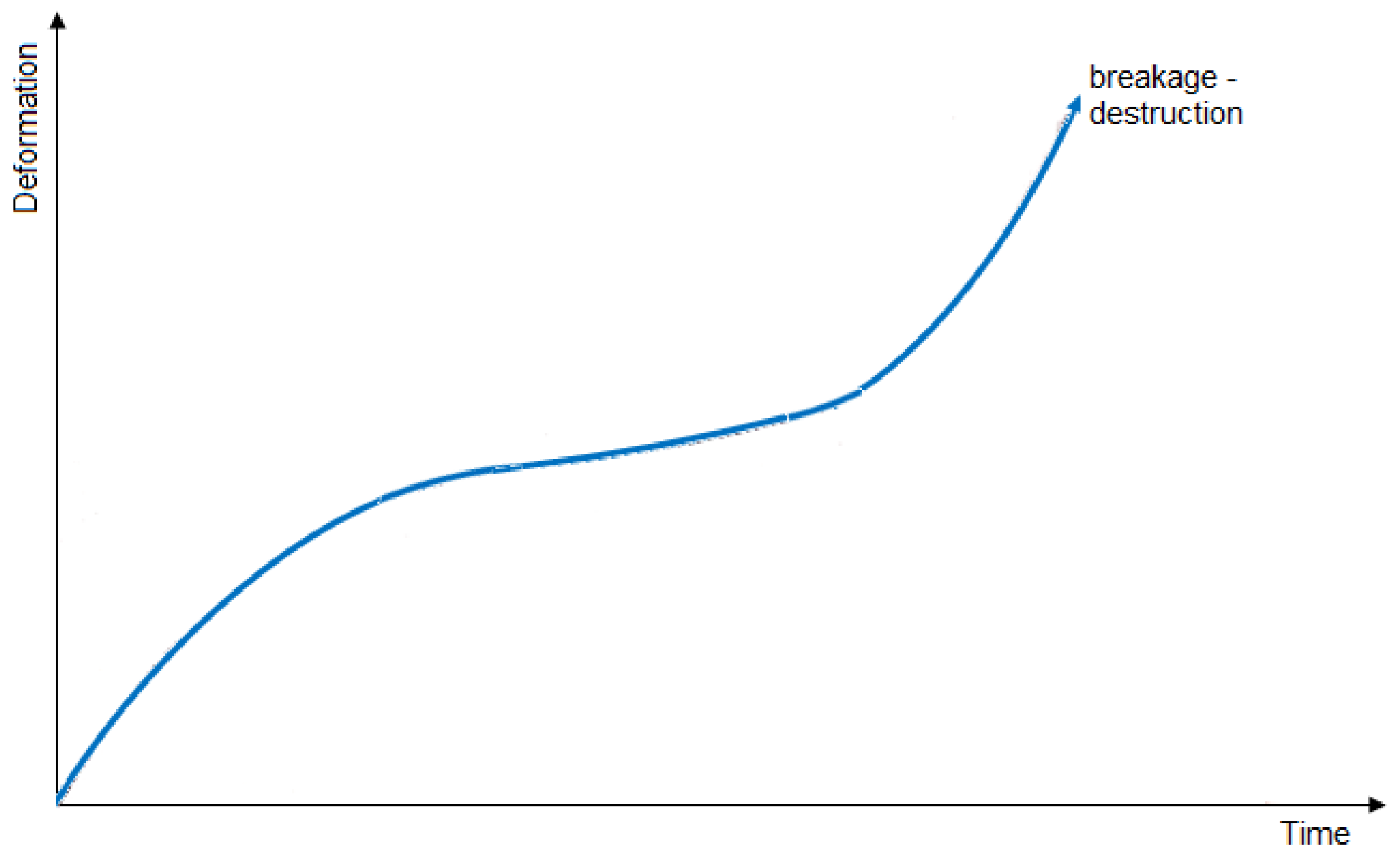
It seems that to explain all aspects of the rocks’ deformation, knowing that their deformation rate is finite, namely, it occurs over time, it is imperative to study the deformation curve as a function of time. The allure of such a rheological curve at the creep (Figure 1) in its generalized form defines a total deformation (εt) which is constituted according to the principle of the partition of deformations, from:
ε t = ε 0 + ε p + ε p + ε p
where ε0 is an instantaneous deformation created by the stress under which the test is performed; εp is a primary plastic deformation that represents the recorded deformation over time and which characterizes the area of the unstabilized creep; εp′ is a secondary plastic deformation represented by the recorded deformation in the area in which the curve follows an oblique or horizontal asymptote and which characterizes the stabilized creep area; and εp″ is a tertiary deformation, measured in the area of the quickly increasing area of deformation until the breaking and characterizes the breaking zone.

3. Deformation Characteristics in Time of Altered Andesite

3.1. Deformation Characteristics in Time of Altered Andesite Established in Laboratory

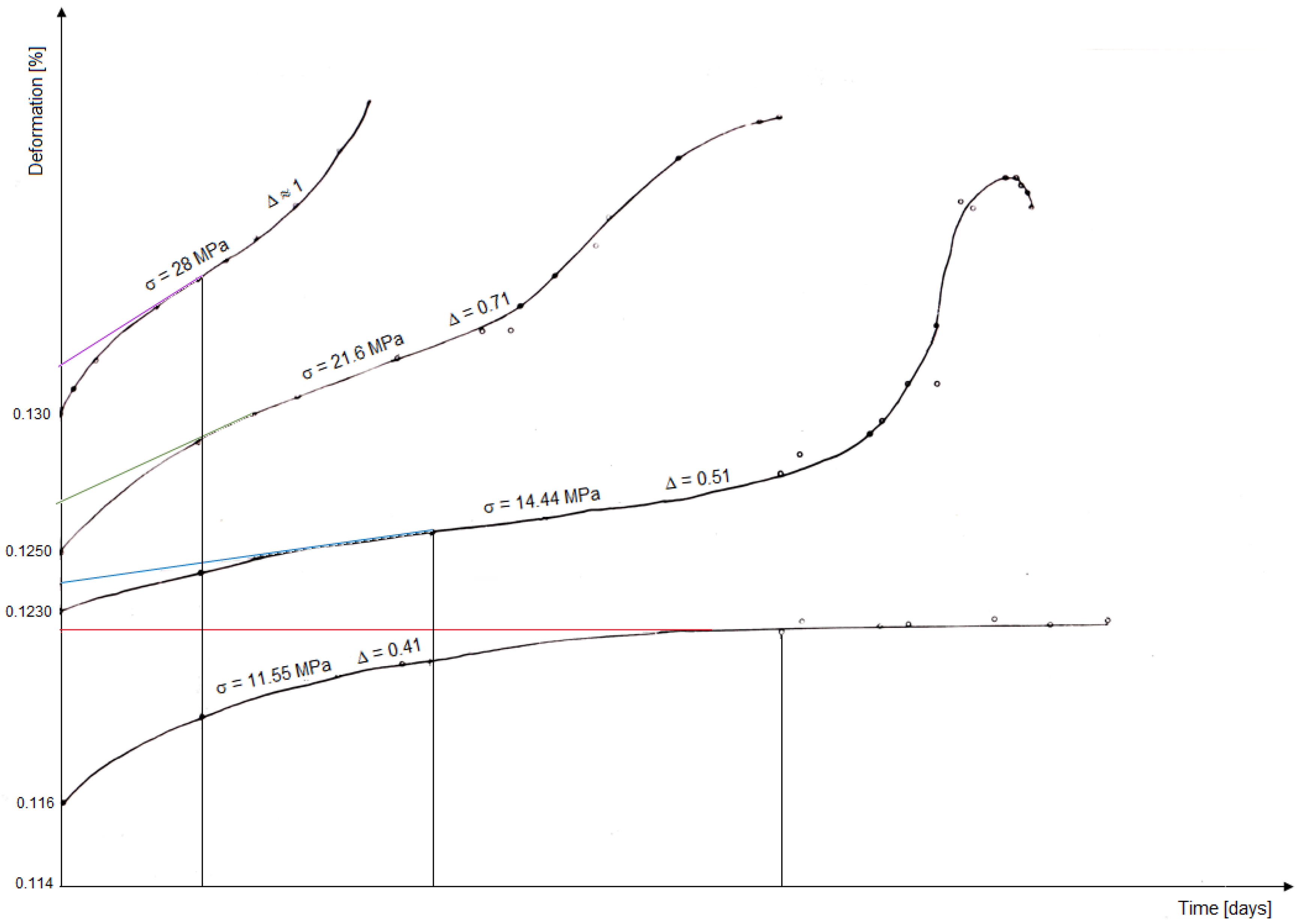
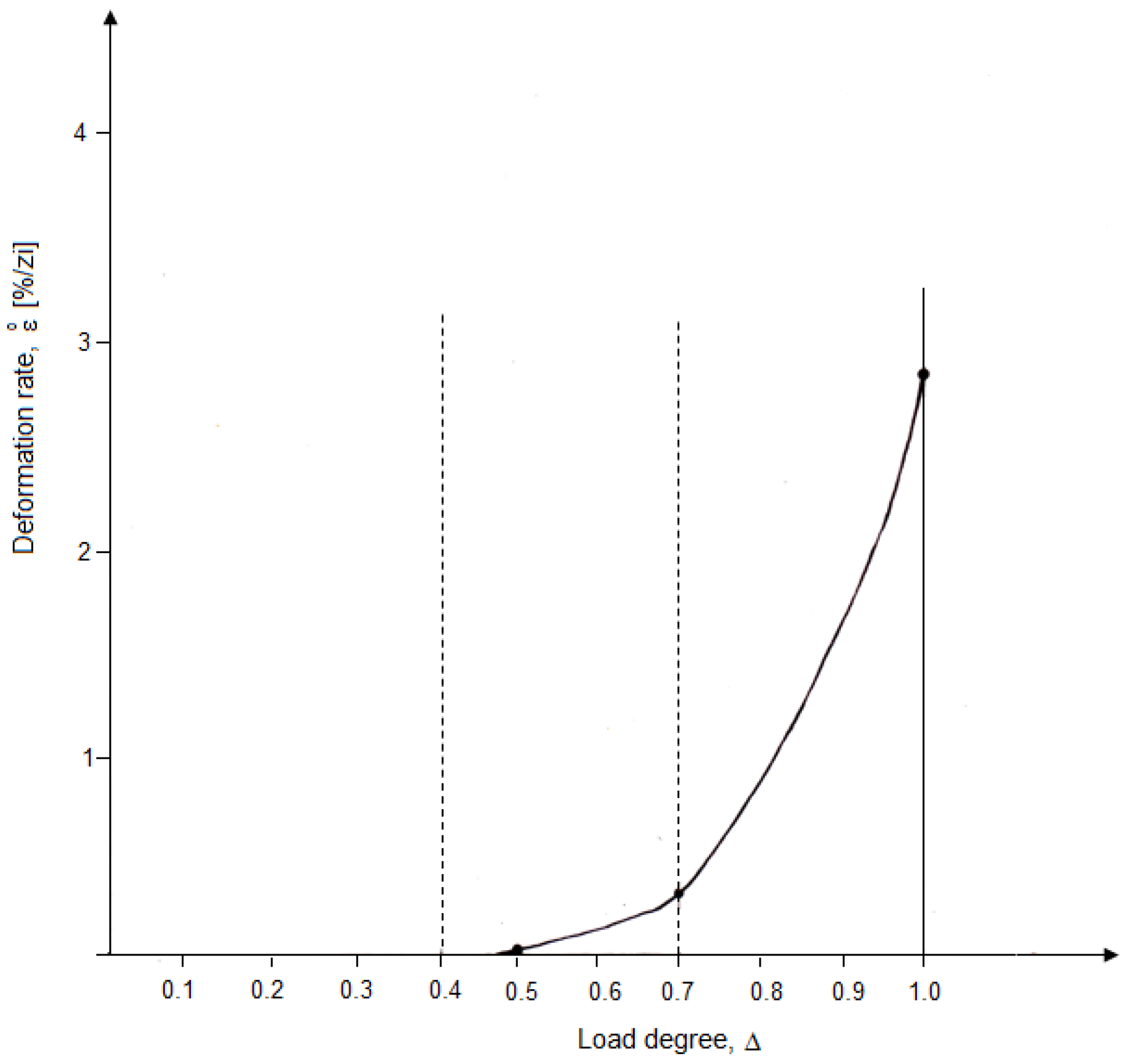
For the study of the creep characteristics and the mathematical establishment of the law of deformation in time of the andesite rocks type, the rheological tests were performed on intensively hydrothermal metamorphosed pyroxene andesite; these being the most unfavorable in terms of their stability. The creep tests were performed on uniaxial compression, with different stresses corresponding to the load degree of the andesite samples, according to the data in Table 1. The obtained results are shown in Table 2 and Figure 2 and Figure 3.
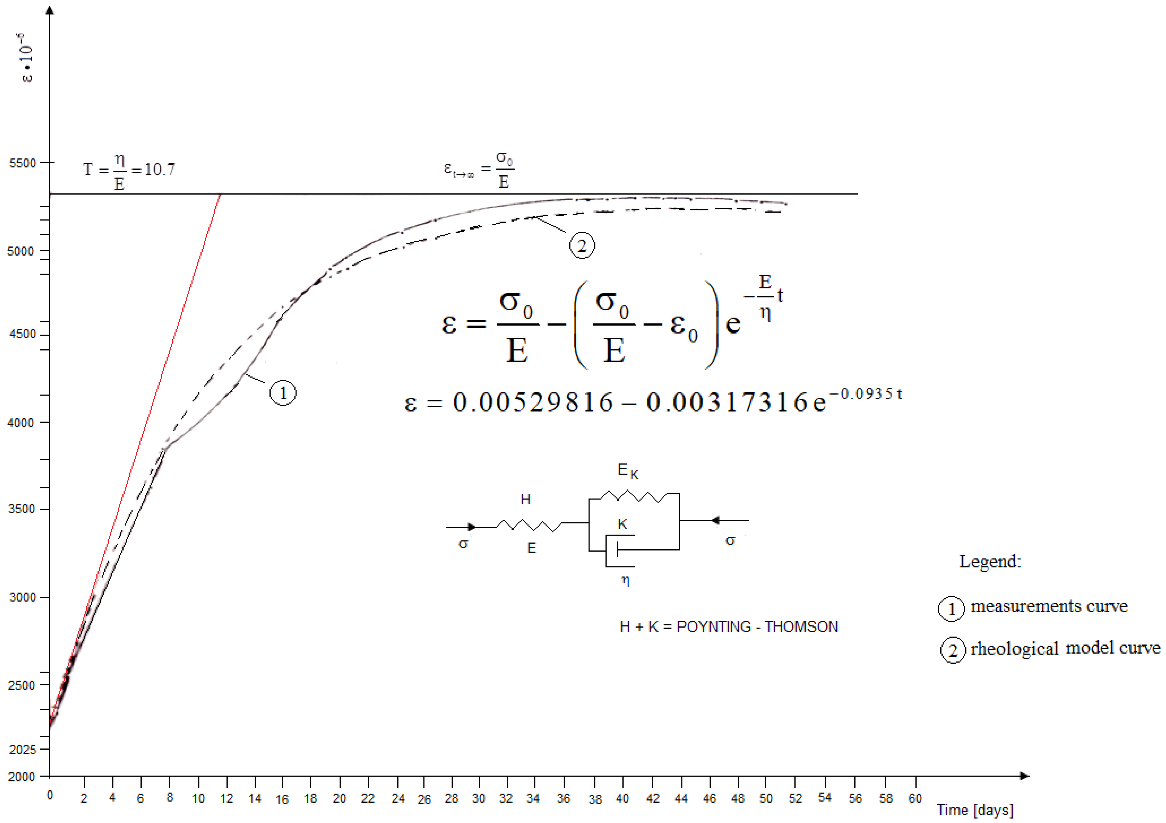
Through analyzing the experimental creep curve obtained by the tests, based on the data provided by the specialized literature [3,4,5,10,15,19,24,25,26,30,32,33,40,41,42], it is found that the Poynting–Thomson model is the model with which we could assimilate the deformation in time of strongly hydrothermal metamorphosed pyroxene andesite rock types. Because the assumption implies a confirmation in this regard, we took the model with the creep equation and analyzed it based on the obtained data from the tests through an analytical processing. The functional equation of the rock deformation in time can be expressed in the following form:
ε = f ( t )
The explanation of this function according to the Poynting–Thomson model for a uniaxial compression test becomes:
ε = σ 0 E ( σ 0 E ε 0 ) e E η t
where σ0 is the load stress, MPa; E is the modulus of elasticity, MPa; ε0 is the instantaneous elastic deformation; η = T E is the coefficient of viscosity, Ns/m2; and t is the time.
Or, Equation (3) can be written in the form:
ε = a b e c t
in which the following substitutions were made:
a = σ 0 E   ;   b = σ 0 E ε 0   ;   c = E η = E T E = 1 T
Based on the fact that from the experimental data we can choose two arbitrary points with the abscissa t1 and t2, and having the obtained values from the creep test for a stress equal to σ0 = 11.55 MPa, then:
t 3 = t 1 + t 2 2   ;   a = ε 1 ε 2 ε 3 2 ε 1 + ε 2 2 ε 3
which become:
t 3 = 7.135 + 51.5 2     t 3 = 29.3125   days
and:
a = 3637 × 10 6 × 5291 × 10 6 ( 5180 × 10 6 ) 2 3637 × 10 6 + 5291 × 10 6 2 × 5180 × 10 6     a = 5299.50 × 10 6
where the value 0.005180 represents ε3, which corresponds to t3 and which was determined by interpolation.
Knowing that:
b = σ 0 E ε 0 = a ε 0
then:
b = 5299.50 × 10 6 2125 × 10 6     b = 3174.50 × 10 6
Equation (3) can also be written in the form:
ε a = b e c t   o r   a ε = b e c t
making the logarithm of Equation (11), it results in:
lg ( a ε ) = lg b c t lg e
noting:
p = lg ( a ε )   ;   B = lg b   ;   C = c lg e
then, we get the relationship:
p = B C t
the value of B is determined according to the relation (13), resulting:
B = lg ( 3174.5 × 10 6 ) = 3.5016753 + lg ( 10 6 )
knowing the value of B, from Equation (13), we can obtain the value of C:
p i = n B C t i
from where:
i = 1 n p i = n B C i = 1 n t i
therefore, the value of C will be given by the relation:
C = n B i = 1 n p i i = 1 n t i
where i = 1 n p i ;   i = 1 n t i were determined based on resulted data from the creep test and n = 25 is the number of obtained data.
Namely:
C = 25 × ( 3.5016753 + lg 10 6 ) ( 53.64918405 + lg 10 6 ) 673.665     C = 0.0503
whence:
c = C lg e = 0.0503 0.434     c = 0.115898617     c = 0.116
it is known that:
ε i = ε i + ( ε c ) i s   ;   i = 1 , 2 , , n
and:
s = i = 1 n ( ε ε ) i i = 1 n ( ε c ) i
once the value of c (the first approximation) is established, Equation (3) becomes:
ε = a b e c t
which the derivative with respect to c will be:
ε c = b t i e c t i
from the processing of the obtained experimental data, it can easily determine the value of (s), that is:
s = 190.78 84 , 512.8     s = 0.0225
in this case, it turns out:
c = = c + s     c = = 0.0935
where c = represents the second approximation.
On the basis of c = , the accuracy increases from 0.520404 to 0.097772. Equation (3), respectively (23), becomes:
ε = = a b e c = t
returning to the substitutions made, the relation (5), we can now determine the search parameters of the creep curve. So:
E = σ 0 a E = 11.55 0.0052995     E = 2179.4   MPa
this value confirms the good results of the elasticity module determined in the laboratory.
T = 1 c =     T = 1 0.0935     T = 10.7   days
and:
η = T × E     η = 2179.4 × 10.7     η = 23319.6   MPa × day
therefore, Equation (6) becomes:
ε = 0.00529816 0.00317316 e 0.0935 t
Equation (31) represents the analytical equation established for the strongly metamorphosed andesite that has been analyzed and which confirms that this rock can be assimilated as a manner of behavior in time with the model given by the Poynting–Thomson model (see Figure 4).

3.2. Deformation Characteristics in Time of Altered Andesite Established In Situ

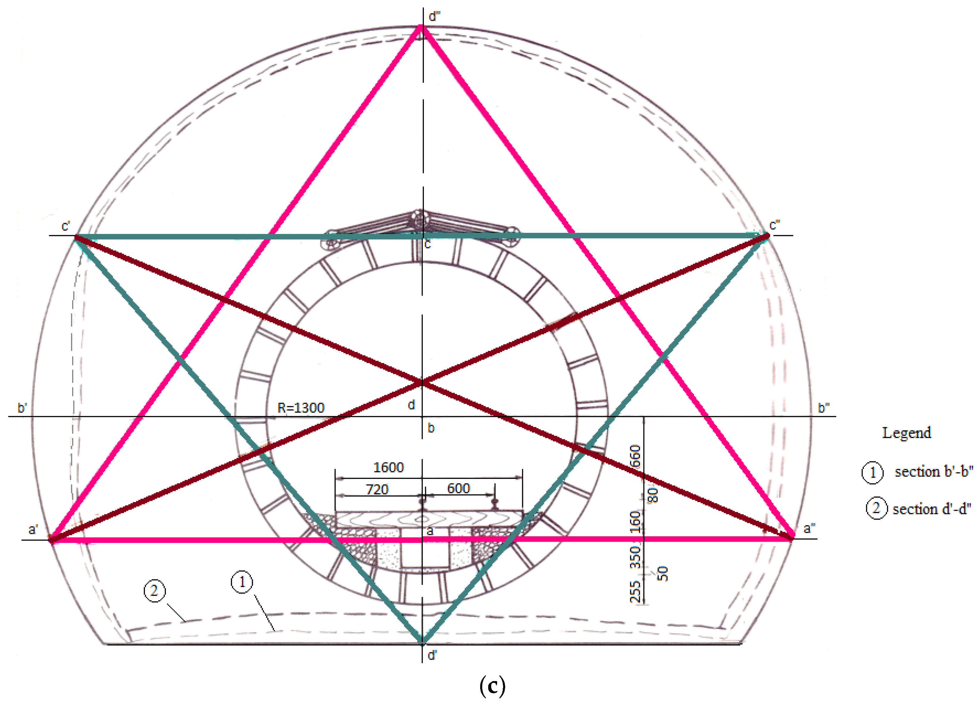
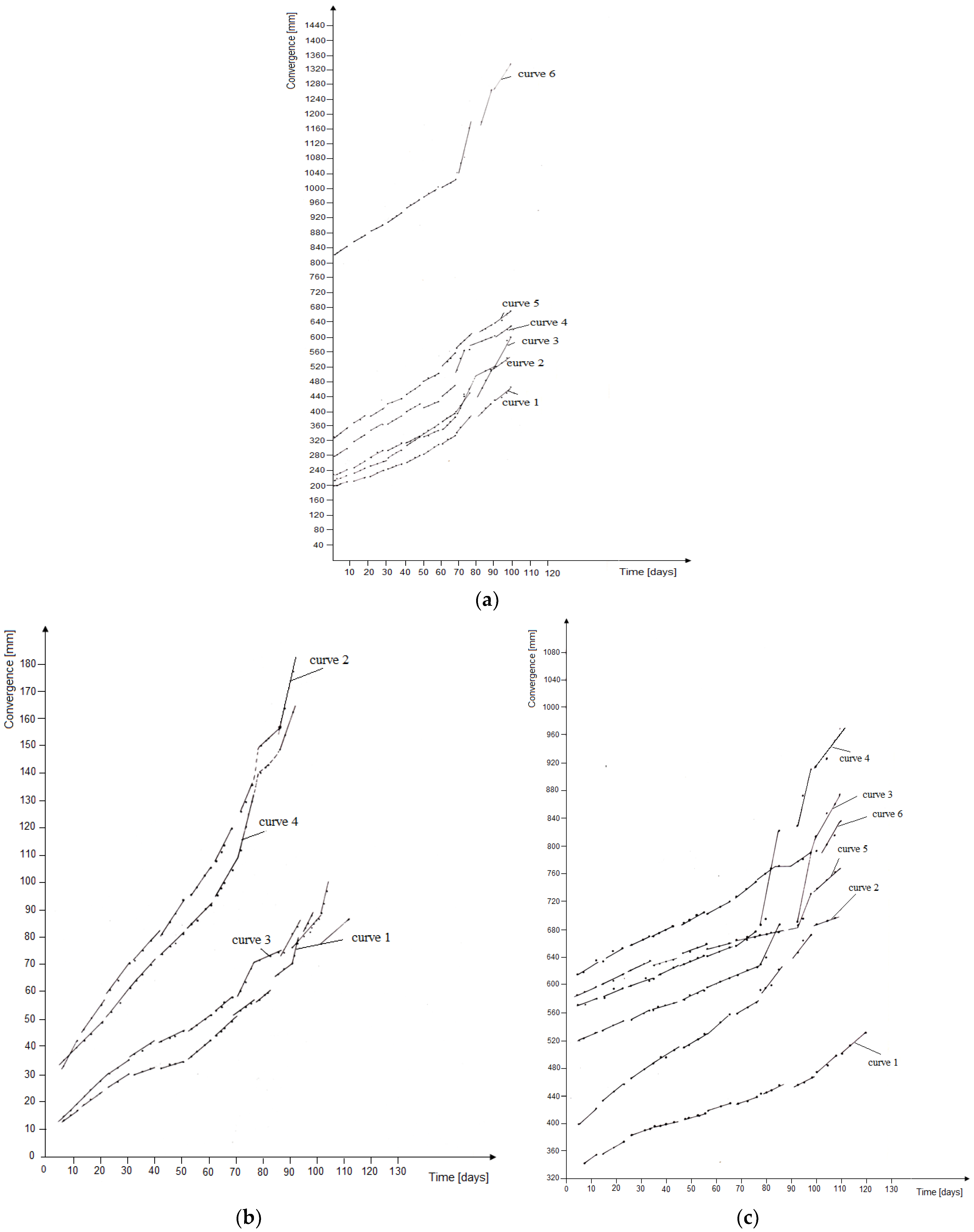
In parallel with the tests performed in the laboratory, the in situ measurements have also been made regarding the deformation in time of the rocks (convergence) around the mining works that intercept the rock types of the highly hydrothermal metamorphosed andesite (Appendix A). The measurements were made in cross sections in the direction of the galleries in the following underground works: a trapezoidal cross gallery (Figure 5a); a directional gallery with an arched profile with straight walls (Figure 5b); and a directional gallery with a circular profile (Figure 5c).
The convergence measurements were extended over a period of 3 years and the obtained results were used in order to establish the laws of variation in the time of the rock’s movement on the outline of the mining works, that is, the laws of relaxation and creep.

3.2.1. Relaxation Law

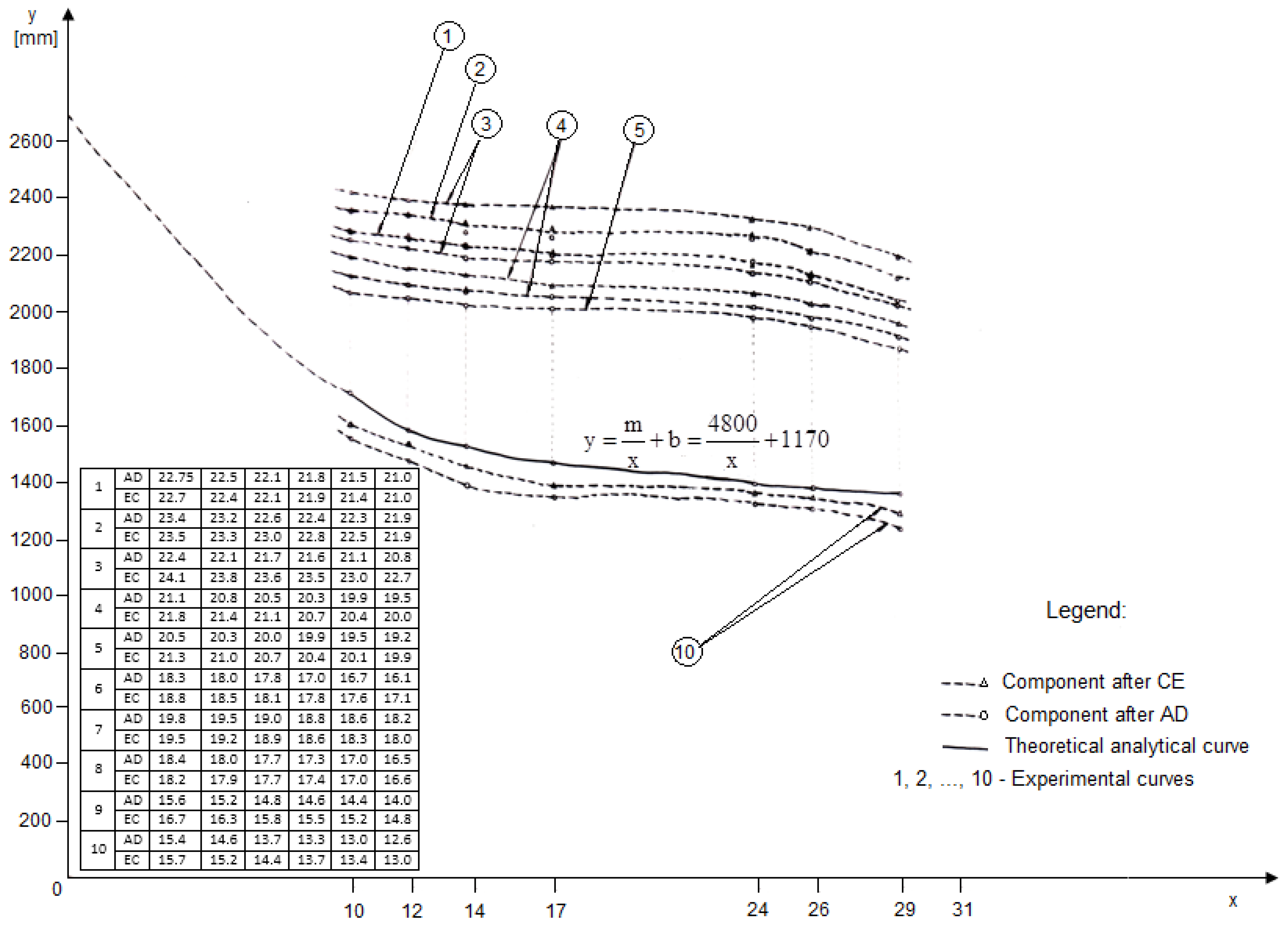
Following the graphical and analytical processing of the convergence values (Figure 6) taken as the displacements, it turns out that, in time, they are determined by a law of variation whose analytical form could be established with the help of mathematical statistics.
A time variation law of the movements on the contour of the gallery resulted in the forming of the equation:
y = 8 m x + b
where y is the values of the displacements according to the direction of measurement; x is the time at which these displacements were measured; and m and b are the numerical coefficients of the equation, whose minimum values are shown in Table 3.

3.2.2. Creep Law

In order to establish such a law, two following deformation methods of the contour of the underground work have been developed in time [10,11,45,46], namely, the threshold method and the gradient method. This second method, chosen for the interpretation of the measurements results, is based on the general considerations regarding the evolution of the deformation phenomenon; that is, when a cause (in our case, an underground excavation) comes to disturb the rock massif equilibrium, it will tend to evolve to a new state of equilibrium, which concretizes in deformations that should be amortized when the disturbing cause ceases.
However, in reality, these deformations increase continuously, and therefore the deformation phenomenon presents an unamortized evolution until the destruction of the mining work (if the support is inadequately designed according to the real working conditions). The problem that arises in such situations is to detect accelerations in the production of deformations, which will in fact indicate the occurrence of the failure phenomenon of the underground work and its destruction.
However, the laboratory tests allow us to specify that a linear evolution of the deformation measurements can be approximated by a damped curve, in which case there is an ambiguity regarding the stability of the underground work and, therefore, the observations cannot be stopped but must be continued (Figure 7).
Only if the evolution of the deformations indicates an acceleration of them, then we can predict with certainty the beginning of the phenomenon of the destruction of the underground work because, from a rheological point of view, the breaking of the rocks is always preceded by a short acceleration of the deformations (Figure 8).
Therefore, the chosen method is not based on the final value of the deformation reached at any given moment but on the analysis of the evolution of these deformations compared to their history, that is to say, with their previous evolution.
Such a research method requires complex observations, capable of memorizing the history of in situ deformations; by this, the fluctuation range due to the vulnerability can be reproduced, the general sense of the evolution and the abnormal variation, and the index of the start of the destruction process of the rock’s support system. Such a result can be achieved by considering from the beginning the making of successive and punctual measurements, corresponding to a range, so that in the end we can obtain the evolution of the deformations as true and real as possible.

4. The Gradient Method

The gradient method is based on general considerations regarding the evolution of the deformation phenomenon (Appendix D). Based on the measurements made in each range of time, it is found that the deformations in this range (defined by at least three points) are defined by a straight line. With the help of the smallest squares, the characteristics of the line were established:
D = a i t + b i
where ai is the slope of the straight; bi is the y-coordinate to the origin; and t is the time starting with the first day of the interval measurement.
Taking into account the variability of daily measurements, based on the given data, it was possible to decide whether the observed slope (ai) is significant either for an increase in the deformations, for a decrease in the deformations, or on the contrary, if the deformations were constant during the range of measurement. This decision can be materialized by the concepts of convergence, divergence and constancy.
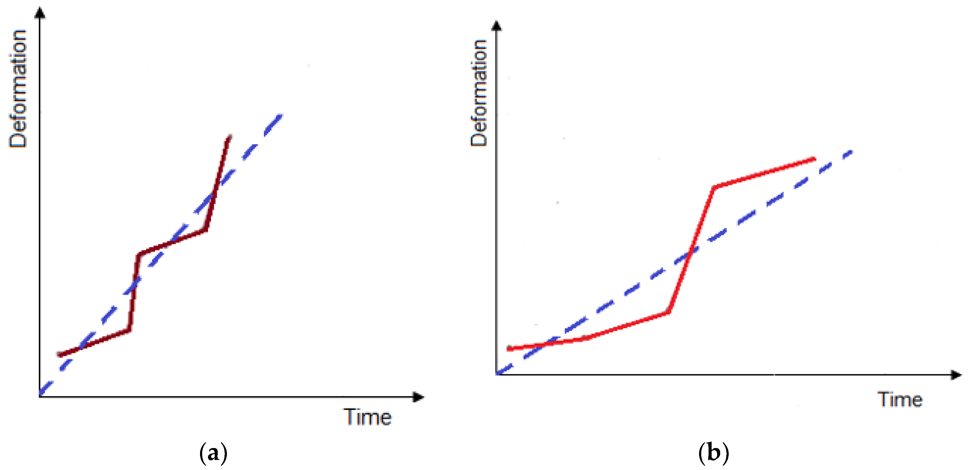
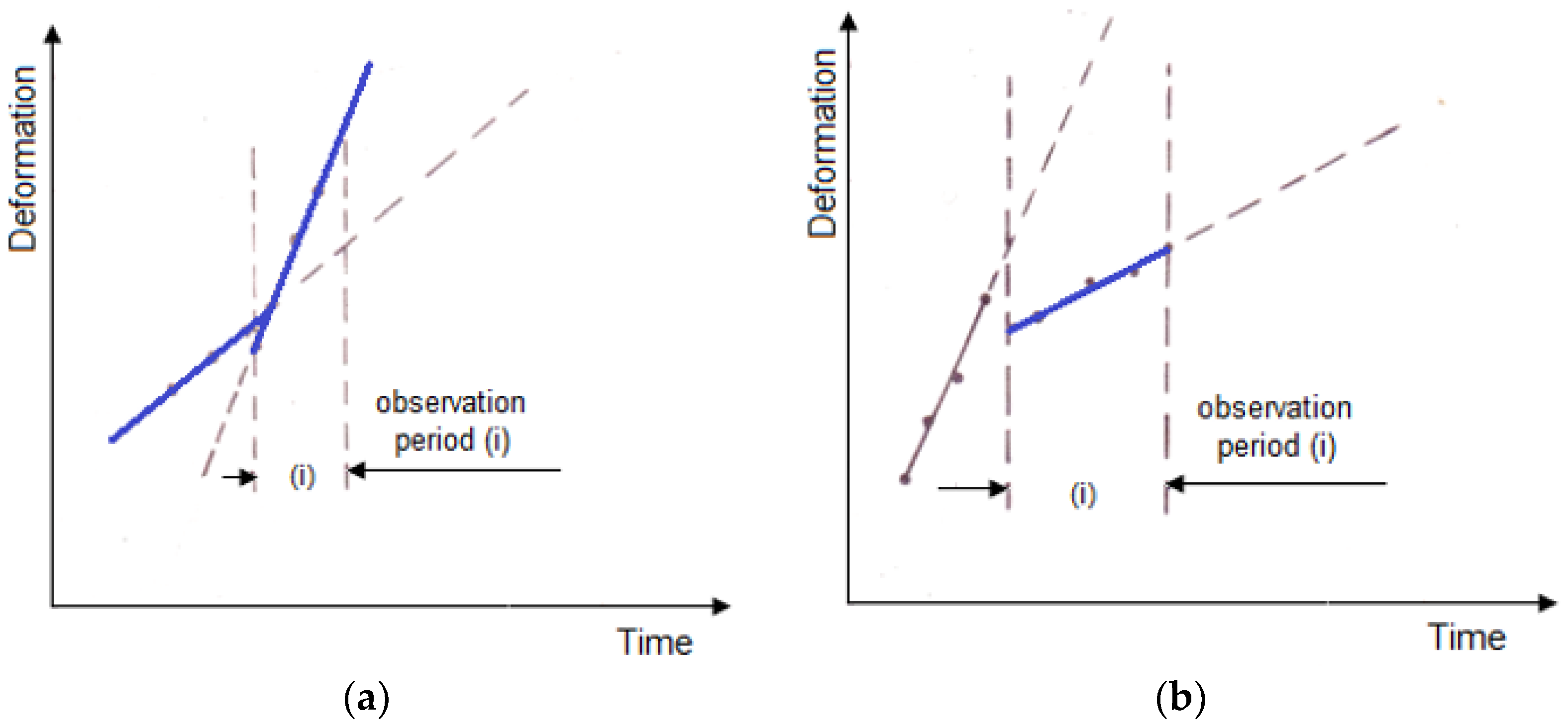
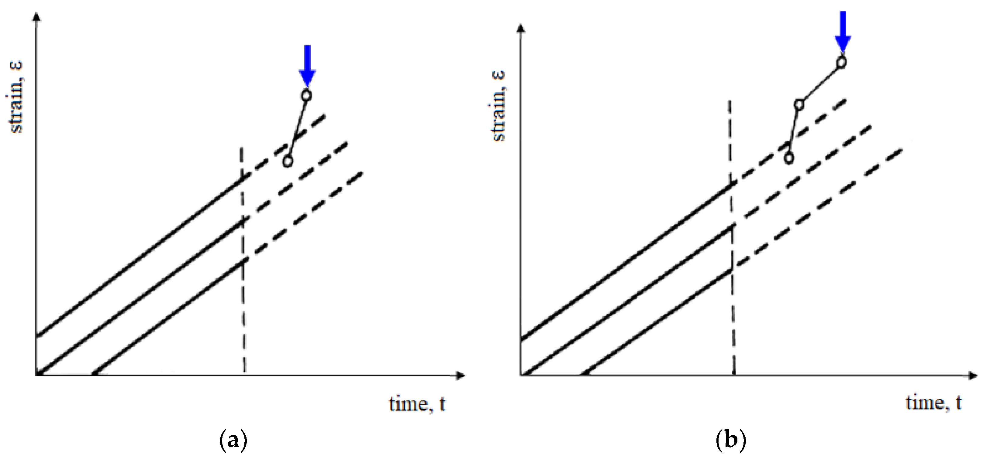
Therefore, the gradient method actually starts with a comparison between the observed central tendency and the tendency that characterized the past. This comparison is actually stored in the form of the straight line given by Equation (33) in the measurement interval (i) and a certain dispersion (σ). The dispersion will indicate an increase in the amplitude of the jumps in the deformation process (Figure 9), and the comparison of the slopes establishes the concavity of the mean deformation curve (Figure 10). Thus, by comparing the dispersions σ′ and σ″, we can decide, for example, whether σ″ is significantly much larger than σ′, either as a deterioration of the measuring device or an increase in the amplitude of the jumps in the deformation process (Figure 9). If the slope difference (ai+1 – ai) is large, then it means either an acceleration or stabilization according to the sign of this difference.
If the difference (ai+1−ai) is large, taking into account the variability of the daily measurements, it will be concluded by the difference that it is either an acceleration or a stabilization. If the two straight lines are identical, the data for week (i) will be added to the previous data for defining the straight, which will be taken as the reference straight for the week (i + 1):
D = a 0 i + 1 t + b 0 i + 1
and the straight line of the week (i) will be: D = ait + bi as the reference straight line for the week (i + 1).
Observations can be made on a daily basis, comparing the obtained measurement with the reference straight line, taking into account the dispersion (σ) that characterizes the variability of the measurements. This allows you to set a first alarm level, which involves intensifying the observations or, for example, re-editing the observation. If the next measurement is still higher than the previously observed variation range, the second alarm level can be triggered (Figure 11).
Based on this process, deformations were analyzed in the case of mining works located in andesite. The range of measurement was 10 days, in which 3–4 measurements were made (Appendix B). The graphical representation of the evolution of the deformations in time and their analysis by the gradient method is shown in Figure 12.
The graphical form of the function that shows the law of deformation in time of the contour of horizontal mining works, obtained from the analysis by the gradient method (Figure 10), is in fact identical to the shape of the creep curve.

5. Results and Discussions

We set out to find the mathematical function that will express the law of the search deformation based on the already known form. From a mathematical point of view, the problem is reduced to determining a functional dependence of the variable y (in our case, this variable is the deformation) against another variable x (namely, the time), which can be written as Equation (35) with the obvious identification of all the parameters that come into the definition of a functional dependence:
y = f ( x ;   a 0 ;   a 1 ;   a 2 ; ; a n )
the method that allows us to obtain accurate and consistent estimates of the parameters is: a0, a1, a2, …, an and it is the least-squares method using Cebisev’s polynomials. We chose this method because our functional has a form:
y = b 0 p 0 ( x ) + b 1 p 1 ( x ) + b 2 p 2 ( x ) + + b n p n ( x )
where p0(x); p1(x); p2(x); …; pn(x) is the the orthogonal polynomials of Cebisev on the set of the points x1, x2, …, xn with the weights w(x).
The expression parameters (36) are calculated with the relation:
b j = y k p j ( x k ) w k p j 2 ( x k ) w k   ,   j = 0 ,   1 ,   2 ,   ,   n
which do not depend on the degree n of the searched polynomial.
If the values of the argument are equidistant:
x k + 1 = x k = h   ,   k = 1 ,   2 ,   ,   N 1
the calculation of the orthogonal polynomials Cebisev is greatly simplified, if the variable is changed:
u k = x k x h
where:
x = x 1 + x N 2
taking this into account, the searched polynomial will be:
y = c 0 p 0 ( u ) + c 1 p 1 ( u ) + c 2 p 2 ( u ) + + c n p n ( u )
and the parameters of the polynomial are estimated using the relations:
c j = 1 H j y k p j ( u k )   ,   j = 0 ,   1 ,   2 ,   ,   n ;   n = N
where:
H j = p j 2 ( u k )
and u k = x k x h takes only the whole values: 0; ±1; ±2; …; ±(N − 1)/2 if N is uneven, respectively, and the values ±1/2; ±3/2; …; ± (N − 1)/2 when N is an even number.
Using the special formulas for an even number (N = 2L) and an uneven number (N = 2L + 1) of the obtained observations from the convergence measurements, but also the relations of the calculation of the parameters p1, p2, …, p5, corresponding to the number of measurements within a range of 10 days of the measurement, it was passed to determine the searched functional.
The total number of the measurements varies between 9 and 12 data. For this N, the corresponding relations and parameters were taken (see Table 4), with which the function of the searched polynomial was written.
Because the methodology is identical for each group of measurements, we summarize here the description of a single case, namely when N = 11 (11 measurement data):
p 0 = 1   ;   p 1 = u   ;   p 2 = u 2 10   ;   p 3 = u 3 89 5 u
and then:
y = C 0 p 0 + C 1 p 1 + C 2 p 2 + C 3 p 3
or:
y = C 0 + C 1 u + C 2 ( u 2 10 ) + C 3 ( u 3 17.8 u )
from which the following equation results:
y = ( C 0 + 10 C 2 ) + ( C 1 17.8 C 3 ) u + C 2 u 2 + C 3 u 3
but:
y = ( + 10 C 2 ) + ( 17.8 C 3 ) u + C 2 u 2 + C 3 u 3 C 0 = 1 N y k C 1 = 1 110 ( y 1 y 1 ) + 2 ( y 2 y 2 ) + 3 ( y 3 y 3 ) + 4 ( y 4 y 4 ) + 5 ( y 5 y 5 ) C 2 = 1 858 10 y 0 9 ( y 1 + y 1 ) 6 ( y 2 + y 2 ) ( y 3 + y 3 ) + 6 ( y 4 + y 4 ) + 15 ( y 5 + y 5 ) C 3 = 1 5148 14 ( y 1 y 1 ) 23 ( y 2 y 2 ) 22 ( y 3 y 3 ) 6 ( y 4 y 4 ) + 30 ( y 5 y 5 )
knowing:
u = x k x h   ;   h = x k + 1 x k 1 = x k + 1 x k x = 110 + 10 2 = 60
then:
u = x k 60 10     u = 0.1 x 6
it results:
u = 0.1 x 6 u 2 = 0.01 x 2 1.2 x + 36 u 3 = 0.001 x 3 0.18 x 2 + 10.8 x 216
based on the calculations, according to Table 5, the value of the C0, C1, C2 and C3 coefficient results are obtained.
The equation becomes:
y = 461.97846 + 10.01506 u + 0.25279 u 2 + 0.28044 u 3
based on the substitutions made, according to the relations (51) and given that the variable x represents the time, it results in:
y = 350.41 + 3.73 t 0.048 t 2 + 0.00028 t 3
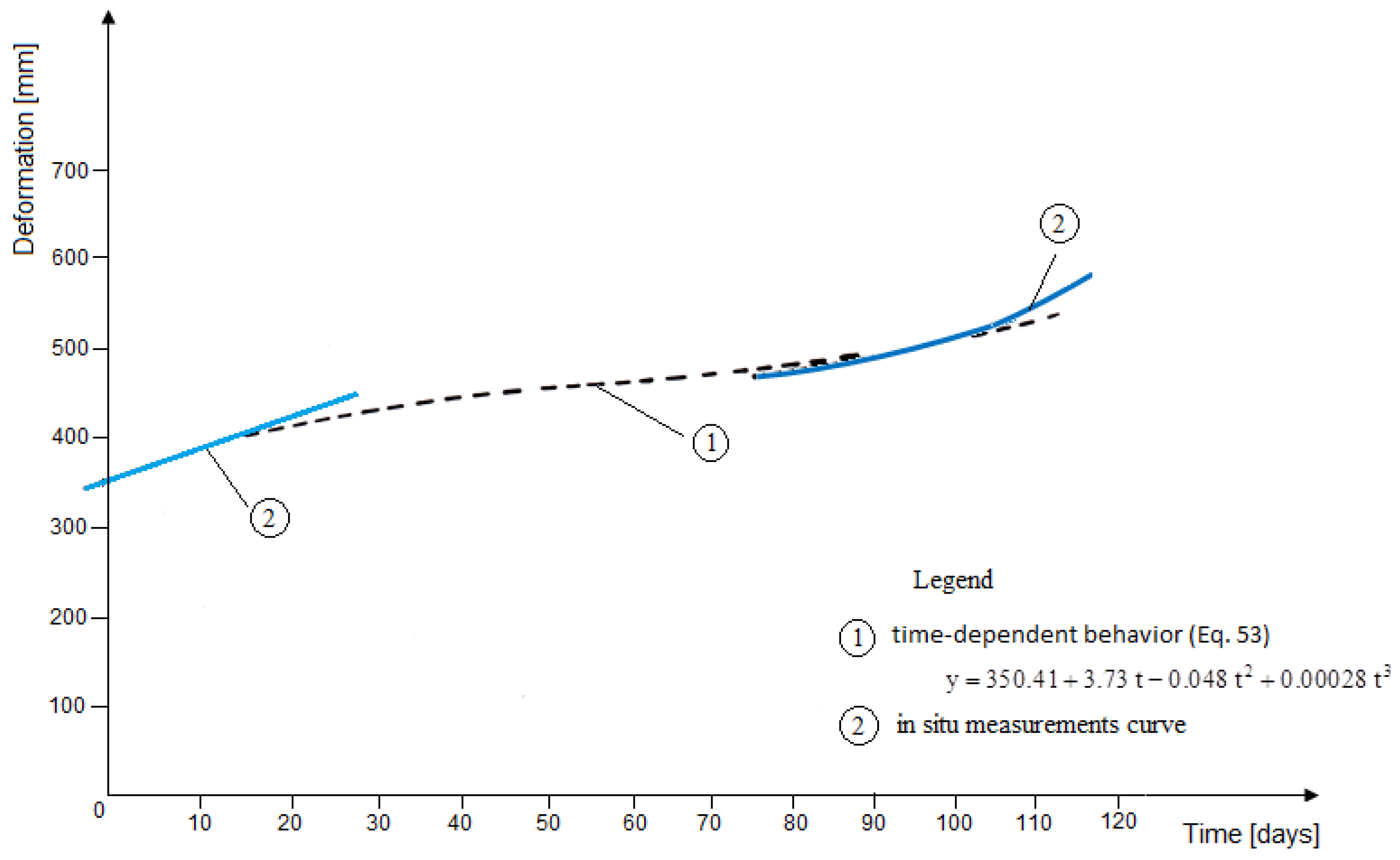
All the data processing led us to the equations of the form obtained above, so we can specify that the law of the deformation in time of the contour of the main horizontal mining works which were made in altered andesite rock type has the main form, given by the relation (53), and whose graphical representation has the shape shown in Figure 13:
ε ( t ) = A + B t + C t 2 + D t 3
Based on the rheological tests performed, the characterization of the altered andesite rock type, it was concluded that for these rocks, the rheological behavior can be assimilated as being the type given by the Poynting–Thomson model. Given the fact that in the actual analyzed in situ conditions, where, due to external factors like the water infiltration but also due to the relative humidity, the alteration phenomenon of the rocks around the horizontal mining works intensifies, having as a consequence the decrease in the bearing capacity, the appearance of the phenomenon of swelling, that is, their change in time, leads us to the conclusion that the use of the Poynting–Thomson model becomes uncertain.
The uncertainty was created by the creep law because it was presented in the form of a damped curve, which actually indicated a stabilization of the deformations (t ≥ 11 days), but not the moment until which the deformation of the highly metamorphosed andesite still retains a certain bearing capacity, the moment from which the breakage begins. Such a curve was therefore incomplete and always ambiguous, because around the horizontal workings, the deformations increased continuously.
The deformation phenomenon presents a continuous evolution and, from a certain moment, increases more and more. In order to fully characterize the behavior under the load, the in situ measurements led us to complete the Poynting–Thomson model in a way which is much more appropriate to the real conditions. The behavior equation is the following:
ε ( t ) = σ 0 E ( 1 + t ) + ( σ 0 E K + σ p E C V ) e E η t
Thus, we proposed the rheological model presented in Figure 14; in principle, the proposed model is based on the following behavior in time under the load and under extremely adverse conditions (the wet area, swelling tendency, etc.).
The particles of eruptive rock are placed so that they are embedded in cement as a product of alteration. In the behavior of the rock under the load, this characteristic determines the appearance of the two stages of deformation (see Table 6): the viscous-elastic stage with a transition to elastic and the elastic–plastic stage.
When a stress is applied, a disturbance of the particles (which have a minimum volume of voids) is created due to the sliding occurring between them and between which a viscous friction occurs. Then, the particles come into direct contact, making the deformation develop further; if the stress increases or external disturbing factors appear, the deformation phenomenon will continue, creating inelastic deformations, namely, elastic–plastic behavior, keeping its cohesion until the plastic limit is exceeded, and it is at this moment when the breakage can occur. Taking into account such a behavior, it results that, giving the rock the possibility to deform in time (t ≥ T), it passes into the field of an elastic–plastic deformation, an area in which it still presents stability. Such a conclusion becomes extremely important in the rock–support interaction phenomenon. On the other hand, also based on the rheological results and using the principles of hereditary theory [6,7,8,10,13,21,30,35], the nucleus of Abel was determined, obtaining the value Φt = 1.49, through which the influence of time can be included in establishing the pressure regime.

6. Conclusions

The necessity to establish the forecast of the stability of the main horizontal mining works in rocks with very different characteristics, involves the assessment of the real value of the properties and firstly of all the anisotropy, heterotrophy and the rheological behavior of the rocks.
The proposed method for studying the evolution of the phenomenon of the deformation in time of rocks around an underground excavation takes into account the fact that the deformation increases continuously, which means that the deformation phenomenon has an undamped evolution until the destruction of the underground work. In such situations, we considered that it is necessary to find accelerations of deformations generation, which will also indicate the occurrence of the delivery phenomenon of the underground work and its failure.
The method chosen is not based on the final value of the deformation reached at any given time but on the analysis of the evolution of these deformations compared to their previous evolution. Based on this process, the deformations in time were analyzed in the case of the mining works located in altered andesite. In relation to the shape of the deformation curve of the horizontal mining works contour, we established the mathematical function that expresses the law of sought deformation. In order to characterize the entire behavior under the load, in situ measurements led us to complete the Poynting–Thomson model much more appropriately to the real conditions. Thus, we have proposed a rheological model that is able to describe the time behavior under the load and in extremely unfavorable conditions (the wet area, swelling tendency, etc.).
The type of the studied rocks is characterized by the fact that they have a low resistance and that, in contact with water, they change their properties. The rocks taken in the study are pyroxenic andesite rocks affected by a medium to high hydrothermal alteration. These are rocks which in their stability area have viscous–elastic–plastic behavior and which can be assimilated by a Poynting–Thomson rheological model when W < WHM or with the proposed model for W > WHM, in which case the phenomenon of swelling occurs (W represents the humidity and WHM is the maximum hygroscopicity). For a period of 56 days, these rocks maintain their stability with the condition that, up to this time limit, the displacements stop. Otherwise, the rocks lose completely their cohesion, the rupture occurs and the pressure on the support will increase, endangering the stability of the underground works.
From this analysis, it follows that a damped evolution alone is not sufficient to predict the stability and finality of in situ observations because when a cause (for example, the execution of an underground excavation) comes to disturb the equilibrium of the rock mass, it will tend to evolve towards a new state of equilibrium, which is characterized by deformations that should be damped when the disturbing cause ceases. In reality, these deformations increase continuously, and therefore the deformation phenomenon shows that an evolution is not damped in time until the moment of the destruction of the mining work (if the support is inadequately designed according to the real working conditions). The problem is to detect accelerations in the generation of deformations that will actually indicate the phenomenon of failure and the destruction of the support.

Funding

This research received no external funding.

Institutional Review Board Statement

Not applicable.

Informed Consent Statement

Not applicable.

Data Availability Statement

Not applicable.

Acknowledgments

I would like to thank the University of Petrosani, which provided the necessary equipment to perform all laboratory tests in prior experimental researches, leading to the results synthesized in this article. I would also like to thank to the mathematician colleagues from Mathematics and Computer Science Department for their support.

Conflicts of Interest

The author declares no conflict of interest.

Appendix A

Table A1. Time deformation of directional gallery with an arched profile with straight walls.
Point Under ObservationDistance between Points (mm)Value of MarksValues of Measurements Made In Situ (Recorded with Deformation Measuring Devices)
Date of Observation
10.0312.0314.0317.0324.0326.0329.0331.0304.0407.0409.04
1 a’aaa’’1040102010321017101710151017101510171015100810111000998982976973973963943951938
b’bbb’’1038108010741069106110641057105910501051104710431041103510351033103110301028102110211003
c’cbb’’975974968970964961943950930943925936921918918924907905901900898893
1430d’ddd’’1070106810691067106710651065106110651060106510571064105810581049105110461051103210511029
2 a’aaa’’1120108011181074111610701103100010801051107610511071105010621046940103293810309261029
b’bbb’’105310511045103210401010103710001022972102097010209701020963101995010159401013938
c’cbb’’995993990991980987969981964972964962962961934952920938920938918938
2800d’ddd’’994991994989992987984975971963965952960949956938952936949935945929
3 a’aaa’’1120109011171078110010701097106510921061109010381081102710731020107010141062100910571003
b’bbb’’1036107010311056102810311018103110051031100310131000920997984992975938970987960
c’cbb’’9901030952102387510108701010870101095410108481000945983840972938969836968
4700d’ddd’’956953956951954951954949953941941945920930916927905922905911905905
4 a’aaa’’10251040102210311019101710151009100710031005100010011000990987988982976977972970
b’bbb’’995993982974975960963959942954947951945949945943940941936936927936
c’cbb’’785893781856780851777835772820762805758792752778952769950965746750
5000d’ddd’’991960985954968942965938960930937925922913920910917903910897902884
5 a’aaa’’967979960972951970948963943953943953940950938948921934918928916922
b’bbb’’965964961955957950951943950930946930942925940920936917928907923904
c’cbb’’795890790874787861783859775857769846762742758732752810942807734803
5000d’ddd’’915911913908907905903905900900898899891897887898871863869852866842
6 a’aaa’’826830825830820830813827810800803794800790800776794756768730760708
b’bbb’’883881871876854868843863832860830860828860789845777836740821730810
c’cbb’’800827774823770820769758765778693775680773678769673760654758645742
4800d’ddd’’998897991895988782986773984768951759920751919748912743898732891722
7 a’aaa’’980981979981977979971977965977957977950975947973943970935952931943
b’bbb’’997994990984988973950932895893884887872880892872870840864840852840
c’cbb’’680720680711680685680683680683680683679680671678662663660658657646
4700d’ddd’’869865832834800810783790760767753746732730728728725722720712715702
8 a’aaa’’876877871863862850854847850841849823846819641813835805828790810782
b’bbb’’875871872865870859868843865836863824860861654659847859640834932823
c’cbb’’740743740739738735735712730704727700719692709685700675698663691654
2600d’ddd’’976971965952950914923914915912903869900891900884891875884862871852
9 a’aaa’’755760753758749745745732740729731729720728720718719710709699704693
b’bbb’’730780721776719760709743700700703699705699700699698698675678661665
c’cbb’’575748570739565730551720550714550709545704532680528640521638516635
2500d’ddd’’960967954887940800928792900785884778829774883762871753869732864728
10 a’aaa’’770762750782710661682659650652643641641638639625636600627598613591
b’bbb’’710747700731692724634702625685621675621614617613602613594607585600
c’cbb’’610607599606593600581600560593558587550579542561534550530546525531
d’ddd’’858781531764798750790742788730768730753728743719740711732703730692

Appendix B

Table A2. The evolution of deformations as a function of time and the results of their analysis for directional gallery with an arched profile with straight walls.
Measuring Range (Days)Measured Values, (mm)SlopeEvolution of DeformationsSlopes ComparisonDispersionOrdinates Comparison
STATION 1—vertical
1–10
(May)
376
383
394
0.67----
10–20
(May)
396
405
414
0.55Applsci 12 11877 i001Applsci 12 11877 i002=Applsci 12 11877 i002
20–30
(May)
422
430
432
435
0.34=Applsci 12 11877 i001==
1–10
(June)
437
439
442
0.25====
10–20
(June)
446
448
452
454
0.25====
20–30
(June)
458
465
470
0.32====
1–10
(July)
469
472
478
0.32====
10–20
(July)
482
484
486
494
0.44====
20–30
(July)
495
498
504
0.44====
1–10
(August)
513
523
537
0.84Applsci 12 11877 i001Applsci 12 11877 i003Applsci 12 11877 i002Applsci 12 11877 i002
10–20
(August)
540
551
571
0.84====
STATION 2—vertical
1–10
(May)
439
446
462
0.84----
10–20
(May)
473
486
496
0.78Applsci 12 11877 i001Applsci 12 11877 i001-Applsci 12 11877 i002
20–30
(May)
504
518
524
0.60====
1–10
(June)
527
536
536
545
0.60====
10–20
(June)
550
554
560
569
0.58====
20–30
(June)
570
586
598
0.84====
1–10
(July)
598
607
614
0.58====
10–20
(July)
632
635
638
661
1.28Applsci 12 11877 i001Applsci 12 11877 i003=Applsci 12 11877 i002
20–30
(July)
686
703
711
1.28===
1–10
(August)
726
732
736
746
0.38=Applsci 12 11877 i002=Applsci 12 11877 i001
STATION 3—vertical
1–10
(May)
625
630
638
0.42----
10–20
(May)
641
646
654
0.42Applsci 12 11877 i001Applsci 12 11877 i001=Applsci 12 11877 i002
20–30
(May)
660
670
674
0.42====
1–10
(June)
668
670
674
676
0.29=Applsci 12 11877 i002=Applsci 12 11877 i001
10–20
(June)
686
687
693
697
0.36====
20–30
(June)
690
695
699
0.21====
1–10
(July)
704
704
709
0.21====
10–20
(July)
711
713
715
716
0.21Applsci 12 11877 i001===
20–30
(July)
726
734
770
2.25=Applsci 12 11877 i003=Applsci 12 11877 i002
1–10
(August)
777
790
801
807
0.90=Applsci 12 11877 i002=Applsci 12 11877 i001
STATION 4—vertical
1–10
(May)
560
562
570
0.36----
10–20
(May)
573
583
588
0.40Applsci 12 11877 i001==Applsci 12 11877 i001
20–30
(May)
589
599
604
0.36====
1–10
(June)
603
608
610
614
0.36====
10–20
(June)
619
624
628
632
0.36====
20–30
(June)
636
644
649
0.36====
1–10
(July)
654
660
666
0.36====
10–20
(July)
669
670
727
1.96Applsci 12 11877 i001Applsci 12 11877 i003=Applsci 12 11877 i002
20–30
(July)
730
798
825
5.67=Applsci 12 11877 i003=Applsci 12 11877 i002
1–10
(August)
832
841
854
875
1.60=Applsci 12 11877 i002=Applsci 12 11877 i001
STATION 5—vertical
1–10
(May)
655
658
674
0.53----
10–20
(May)
674
688
692
0.53Applsci 12 11877 i001===
20–30
(May)
697
705
709
0.42====
1–10
(June)
709
714
718
725
0.51====
10–20
(June)
729
733
740
743
0.51====
20–30
(June)
742
752
759
0.47====
1–10
(July)
767
778
788
0.78=Applsci 12 11877 i001=Applsci 12 11877 i002
10–20
(July)
794
800
808
809
0.78====
20–30
(July)
817
820
829
0.78====
1–10
(August)
852
886
898
912
1.73=Applsci 12 11877 i003=Applsci 12 11877 i002
STATION 6—vertical
1–10
(May)
610
612
620
0.36----
10–20
(May)
622
633
635
0.36Applsci 12 11877 i001===
20–30
(May)
638
648
646
0.36====
1–10
(June)
648
655
663
664
0.36====
10–20
(June)
670
674
678
682
0.36====
20–30
(June)
680
688
694
5.23=Applsci 12 11877 i003=Applsci 12 11877 i002
1–10
(July)
696
708
716
0.73====
10–20
(July)
725
734
850
861
5.67=Applsci 12 11877 i003=Applsci 12 11877 i002
20–30
(July)
968
910
949
3.73=Applsci 12 11877 i003=Applsci 12 11877 i002
1–10
(August)
954
965
990
1000.7
1.38=Applsci 12 11877 i002=Applsci 12 11877 i001
STATION 1—horizontally
1–10
(May)
200
200
204
210
0.38----
10–20
(May)
212
218
221
0.42Applsci 12 11877 i001===
20–30
(May)
225
234
240
0.60====
1–10
(June)
244
249
253
256
0.49====
10–20
(June)
262
267
275
280
0.49====
20–30
(June)
284
297
304
310
0.81=Applsci 12 11877 i001=Applsci 12 11877 i002
1–10
(July)
312
325
327
335
0.73====
10–20
(July)
342
356
376
384
1.38=Applsci 12 11877 i003=Applsci 12 11877 i002
20–30
(July)
398
410
421
1.19===
1–10
(August)
432
439
451
466
0.96=Applsci 12 11877 i002=Applsci 12 11877 i001
STATION 2—horizontally
1–10
(May)
230
230
234
242
0.49----
10–20
(May)
248
258
265
0.62Applsci 12 11877 i001Applsci 12 11877 i001=Applsci 12 11877 i002
20–30
(May)
274
288
294
0.62====
1–10
(June)
294
301
305
315
0.62====
10–20
(June)
316
320
327
332
0.62====
20–30
(June)
340
348
357
366
0.49=Applsci 12 11877 i002=Applsci 12 11877 i001
1–10
(July)
374
382
387
395
1.28=Applsci 12 11877 i003=Applsci 12 11877 i002
10–20
(July)
398
416
430
451
2.47=Applsci 12 11877 i003=Applsci 12 11877 i002
20–30
(July)
464
484
510
0.62-Applsci 12 11877 i002-Applsci 12 11877 i001
1–10
(August)
517
531
546
549
0.96====
STATION 3—horizontally
1–10
(May)
214
220
220
226
0.44-----
10–20
(May)
234
240
246
0.53Applsci 12 11877 i001Applsci 12 11877 i001=Applsci 12 11877 i002
20–30
(May)
252
258
264
0.42=Applsci 12 11877 i002=Applsci 12 11877 i001
1–10
(June)
275
282
288
294
0.75=Applsci 12 11877 i001=Applsci 12 11877 i002
10–20
(June)
308
314
322
330
0.84====
20–30
(June)
348
340
357
366
0.84====
1–10
(July)
374
382
387
395
0.84====
10–20
(July)
398
416
440
451
1.73=Applsci 12 11877 i003=Applsci 12 11877 i002
20–30
(July)
464
484
510
2.47=Applsci 12 11877 i003=Applsci 12 11877 i002
1–10
(August)
519
583
603
2.47====
STATION 4—horizontally
1–10
(May)
330
334
341
354
0.75----
10–20
(May)
370
378
388
0.75Applsci 12 11877 i001===
20–30
(May)
388
398
407
0.75====
1–10
(June)
421
426
434
0.75====
10–20
(June)
446
454
461
471
0.62====
20–30
(June)
482
490
496
504
0.49====
1–10
(July)
524
536
544
559
1.03=Applsci 12 11877 i003=Applsci 12 11877 i002
10–20
(July)
571
584
594
606
3.27=Applsci 12 11877 i003=Applsci 12 11877 i002
20–30
(July)
620
624
634
0.49=Applsci 12 11877 i002==
1–10
(August)
640
647
665
673
0.87====
STATION 5—horizontally
1–10
(May)
278
282
288
298
0.93----
10–20
(May)
318
330
336
0.73=Applsci 12 11877 i001=Applsci 12 11877 i002
20–30
(May)
349
357
365
0.75====
1–10
(June)
367
374
380
388
0.49====

Appendix C

Table A3. Corresponding relations and parameters for the function of the searched polynomial for N = 9; N = 11; and N = 12 measurement data.
Computing Relations for N = 9u p 1 * p 2 * p 3 * p 4 * p 5 *
p 1 = u = p 1 * p 2 = u 2 20 3 = 1 3 p 2 * p 3 = u 3 59 5 u = 6 5 p 3 * p 4 = u 4 115 7 u 2 + 216 7 = 7 p 4 * p 5 = u 5 185 9 u 3 + 716 9 u = 20 3 p 5 * 00−200180
11−17−999
22−8−13−114
337−7−21−11
442814144
γ60924118834323120
H60308 7128 5 41 , 148 7 20,800
H j H j 1 8 1 4 5 2 15 4 22 35 4 8 63 3 53 99
Computing Relations for N = 11u p 1 * p 2 * p 3 * p 4 * p 5 *
p 1 = u = p 1 * p 2 = u 2 10 = p 2 * p 3 = u 3 89 5 u = 6 5 p 3 * p 4 = u 4 25 u 2 + 72 = 12 p 4 * p 5 = u 5 95 3 u 3 + 572 9 u = 40 p 5 * 00−10060
1−9−14−3144
22−6−23−14
33−1−22−6−1
446−6−6−6
55153063
γ110858514834206240
H110 30 , 888 5 41,148249,600
H j H j 1 10 7 4 5 7 1 5 6 2 3 6 2 33
Computing Relations for N = 12u p 1 * p 2 * p 3 * p 4 * p 5 *
p 1 = u = 1 2 p 1 * p 2 = u 2 143 12 = 1 3 p 2 * p 3 = u 3 21 1 4 u = 3 2 p 3 * p 4 = u 4 29 13 14 u 2 103 47 112 = 24 7 p 4 * p 5 = u 5 38 1 18 u 3 + 276 76 144 u = 20 3 p 5 * 1/21−35−72820
3/23−29−191244
5/25−17−−25−1329
7/271−21−33−21
9/2925−3−27−57
11/21155333333
γ2864004772227,456106,080
H143 4004 3 11,583 698 , 944 7 707,200
H j H j 1 11 11 12 9 1 3 8 19 28 8 8 63 7 203 396

Appendix D

Figure A1. Detailed flowchart of the proposed method.
Applsci 12 11877 g0a1
Figure A2. Detailed flowchart of the gradient method.
Applsci 12 11877 g0a2

References

  1. Dubuskin, K.I. Ispâtanie Porod na Polzucesti; Nauka: Novosibirsk, Russia, 1972. [Google Scholar]
  2. Kidibinski, A. Rheological models of Upper Sillesian Carboniferous Rock. Int. J. Rock Mech. Min. Sci. 1966, 3, 279–306. [Google Scholar] [CrossRef]
  3. Reiner, M. Rheology Handbuch der Physik; Spring: Berlin/Heidelberg, Germany, 1958. [Google Scholar]
  4. Reiner, M. Deformation, Strain and Flow, 2nd ed.; K.H. Levis and Coltd: London, UK, 1960. [Google Scholar]
  5. Reiner, M. Reologia; Nauka: Novosibirsk, Russia, 1965. [Google Scholar]
  6. Rozovski, M.I. Izucenie napriajenogo sostoiania vokrug gorizontalnoi vârabotki s ucetom posledeistva v gornâh porodah. Izv. AN URSS OTN 1958, 2, 11–18. [Google Scholar]
  7. Rozovski, M.I. Obrabotka krivâh polzucesti na osnove integralnâh upravenii. Izv. Vuzov Maşinstroenie 1960, 3, 25–44. [Google Scholar]
  8. Rozovski, M.I. Polzucesti i dlitelnoe razruşenie materialov. J. Tehn. Fiz. 1961, 11, 41–48. [Google Scholar]
  9. Aydan, O.; Kawamoto, T. The stability assessment of a large underground opening at great depth. In Proceedings of the 17th International Mining Congress and Exhibition of Turkey (IMCET 2001), Ankara, Turkey, 19–22 June 2001; Volume 1, pp. 277–288. [Google Scholar]
  10. Toderaş, M. Rocks Rheology in the Stability of Underground Mining Works. Study Case: Sedimentary Rocks from Jiu Valley, Romania; Scholars’ Press International Publishing House, Lambert Academic Publishing: Saarbrücken, Germany, 2015; p. 549. ISBN 978-3-639-76796-4. [Google Scholar]
  11. Todorescu, A. Study of Stress-Deformation State around the Mining Works Depending on the Rheological Behavior of the Rock Massif; Section “Mathematical Modeling in Earth SCIENCE”; Mining institute: Petroşani, Romania, 1980. [Google Scholar]
  12. Berest, P. Viscoplasticity in Rock Mechanics, Geomaterials, Constitutiv Equations and Modeling; Elsevier Applied Science: Amsterdam, The Netherlands, 1989; pp. 239–262. [Google Scholar]
  13. Bruckl, E. The Rheology of Specially Continous Mass Creep in Rock. Rock Mech. 1972, 4, 237–250. [Google Scholar] [CrossRef]
  14. Hoek, E. Practical Rock Engineering; RocScience: Toronto, ON, Canada, 2007. [Google Scholar]
  15. Jagger, J.C. Rock Mechanics and Engineering; Cambridge at the University Press: Cambridge, UK, 1972. [Google Scholar]
  16. Jagger, J.C. Elasticity, Fracture and Flow; Methuen: London, UK, 1962. [Google Scholar]
  17. Liu, R. Significance of a Basic Rheological Model in Geology and Its Application. Earth Sci. Front. 2007, 4, 61–65. [Google Scholar]
  18. Liu, R.; Zhang, B.; Zhang, C. The Kelvin Model Describing Rock Materials with Behaviour of a Viscoelastic Solid. Earth Sci. Front. 2008, 3, 221–225. [Google Scholar]
  19. Navroski, P.A.; Mroz, Z. Constitutive model for rocks accouting for vâscoplastic deformation and damage. In Proceedings of the 33rd U.S. Symposium on Rock Mechanics, Santa Fe, New Mexico, Mexico, 3–6 June 1992; Balkema: Rotterdam, The Netherlands, 1992. [Google Scholar]
  20. Reiner, M. Outline of a Systematic of Rheological Theories; Selected Papers on Rheology; Elsevier Scient Publishing Company: Amsterdam, The Netherlands, 1975. [Google Scholar]
  21. Stolle, D.F.E. Viscoelasticity and Plasticity Numerical Stability Revisited. In Proceedings of the 3rd International Symposium. On Numerical Models in Geomechanics, Niagara Falls, ON, Canada, 8–11 May 1989; Elserer Applied Science: London, UK, 1989. [Google Scholar]
  22. Zhong, T. Overview of the rheological models for rocks. IOP Conf. Ser. Earth Environ. Sci. 2019, 358, 032020. [Google Scholar] [CrossRef]
  23. Toderaş, M. Rheological model for analyzing of the underground excavations stability based on the principle of interaction. Min. Rev. 2008, 5–6, 20–22. (In Romanian) [Google Scholar]
  24. Li, Z.; Li, Z.; Liu, J.; Xu, R.; Xu, R.; Shi, W. Study of grouting effectiveness based on shear strength evaluation with experimental and numerical approaches. Acta Geotech. 2021, 16, 3991–4005. [Google Scholar] [CrossRef]
  25. Xu, R.; Xu, R.; Zhang, S.; Li, Z.; Li, Z.; Yan, X. Experimental investigation of the strain rate effect on crack initiation and crack damage thresholds of hard rock under quasi-static compression. Acta Geotech. 2022. [Google Scholar] [CrossRef]
  26. Wang, M.; Chen, B.; Zhao, H. Data-driven rock strength parameters identification using artificial bee colony. Buildings 2022, 12, 725. [Google Scholar] [CrossRef]
  27. Liu, F.Z. Study of the Stability of Surrounding Rock Deep Roadway; Shandong University of Science and Technology: Qingdao, China, 2005. [Google Scholar]
  28. Xu, X.; He, M.; Gao, Y. Study on Mining Pressure Law and Pressure Relief Control under Influence of Key Layer. Min. Metall. Explor. 2021, 38, 1985–1996. [Google Scholar] [CrossRef]
  29. Toderas, M.; Moraru, R. The Effect of Increasing the Water Content on Rocks Characteristics from Suior, Romania. Min. Miner. Depos. J. Min. Miner. Depos. 2017, 11, 1–14. [Google Scholar] [CrossRef] [Green Version]
  30. Hirian, C. Rock Mechanics; Didactic and Pedagogical Publishing House: Bucharest, Romania, 1981. (In Romanian) [Google Scholar]
  31. Nasonov, L.N. Mehanika gornâh porod i kreplenie gornâh vârabotok; Nedra: Moskva, Russia, 1969. [Google Scholar]
  32. Todorescu, A.; Hirian, C.; Gaiducov, V.; Arad, V.; Toderaş, M. Theoretical—Experimental Research Regarding the Assesment an Approach Method of Geomechanical Characteristics of Rocks Reinforced by Injection of Cement; Research Project with MCT; Ministry of Research: Bucharest, Romania, 1994–1997; Nr.369B/B/. (In Romanian) [Google Scholar]
  33. Toderaş, M. Rock Mechanics, Soil and Underground Constructions; Universitas Publishing House: Petroşani, Romania, 2014; Volume II, p. 1167, ISBN 978-973-741-381-9, p. 516, ISBN 978-973-741-383-3. (In Romanian) [Google Scholar]
  34. Toderaş, M.; Danciu, C. Stability Analysis Methods of Underground Mining Works; Lambert Academic Publishing: Toronto, ON, Canada, 2017; p. 380. ISBN 978-620-2-19847-9. [Google Scholar]
  35. Griggs, D.T. Creep of Rocks. J. Geol. 1939, 47, 225–251. [Google Scholar] [CrossRef]
  36. Goodman, R.E. Introduction to Rock Mechanics; John Wiley: Hoboken, NJ, USA, 1981. [Google Scholar]
  37. Mohammad, R.Z.; Ahmad, F. Analytical solutions for the stresses and deformations of deep tunnels in an elastic-brittle-plastic rock mass considering the damaged zone. Tunn. Undergr. Space Technol. 2016, 58, 186–196. [Google Scholar]
  38. Stagg, K.G.; Zienkievici, O.C. Rock Mechanics in Engineering Practice; John Wiley: Hoboken, NJ, USA, 1968. [Google Scholar]
  39. Wardle, L.J. The equivalent anisotropic properties of layered rock and soil masses. Rock Mech. 1972, 4, 155–175. [Google Scholar] [CrossRef]
  40. Toderaş, M. Guide to the Design of Underground Mining Works; Universitas Publishing House: Petroşani, Romania, 2015; p. 214. ISBN 978-973-741-432-8. (In Romanian) [Google Scholar]
  41. Erjanov, J.S. Teoria Polzucesti Gornâh Porod i ee Prilojenia; Nauka: Alma, Kazakhstan, 1964. [Google Scholar]
  42. Hoek, E. Reliability of Hoek-Brown estimates of rock mass properties and their impact on design. Int. J. Rock Mech. Min. Sci. 1998, 35, 63–68. [Google Scholar] [CrossRef]
  43. Park, K.; Kim, Y. Analytical solution for a circular opening in an elastic-brittle-plastic rock. Int. J. Rock Mech. Min. Sci. 2006, 43, 616–622. [Google Scholar] [CrossRef]
  44. Sharan, S.K. Elastic-brittle-plastic analysis of circular openings in Hoek-Brown media. Int. J. Rock Mech. Min. Sci. 2003, 40, 817–824. [Google Scholar] [CrossRef]
  45. Sharan, S.K. Analytical solutions for stresses and displacements around a circular opening in a generalized Hoek-Brown rock. Int. J. Rock Mech. Min. Sci. 2008, 45, 78–85. [Google Scholar] [CrossRef]
  46. Kubetsky, V.L. Investigation of Stresses in Pressure Tunnel Linings with regard to creep of concrete and surrounding rock mass. In Proceedings of the 2nd Congress of the International Society of Rock Mechanics, Belgrade, Serbia, 21–26 September 1970; pp. 4–9. [Google Scholar]
  47. Fine, J.; Tincelin, E. Determination de la stabilité des edifices souterraines galeries, tunnels, pilliers, grandes cavités. Rev. L’Ind. Miner. 1971, 2, 117–122. [Google Scholar]
  48. Zeng, C.; Zhou, Y.; Zhang, L.; Mao, D.; Bai, K. Study on overburden failure law and surrounding rock deformation control technology of mining through fault. PLoS ONE 2022, 17, e0262243. [Google Scholar] [CrossRef] [PubMed]
  49. Wang, H.; Jiang, C.; Zheng, P.; Li, N.; Zhan, Y. Deformation and failure mechanism of surrounding rocks in crossed-roadway and its support strategy. Eng. Fail. Anal. 2020, 116, 104743. [Google Scholar] [CrossRef]
  50. Xu, Q.; Li, Y.; Lu, J.; Zhang, L. The use of surrounding rock loosening circle theory combined with elastic-plastic mechanics calculation method and depth learning in roadway support. PLoS ONE 2020, 15, e0234071. [Google Scholar] [CrossRef]
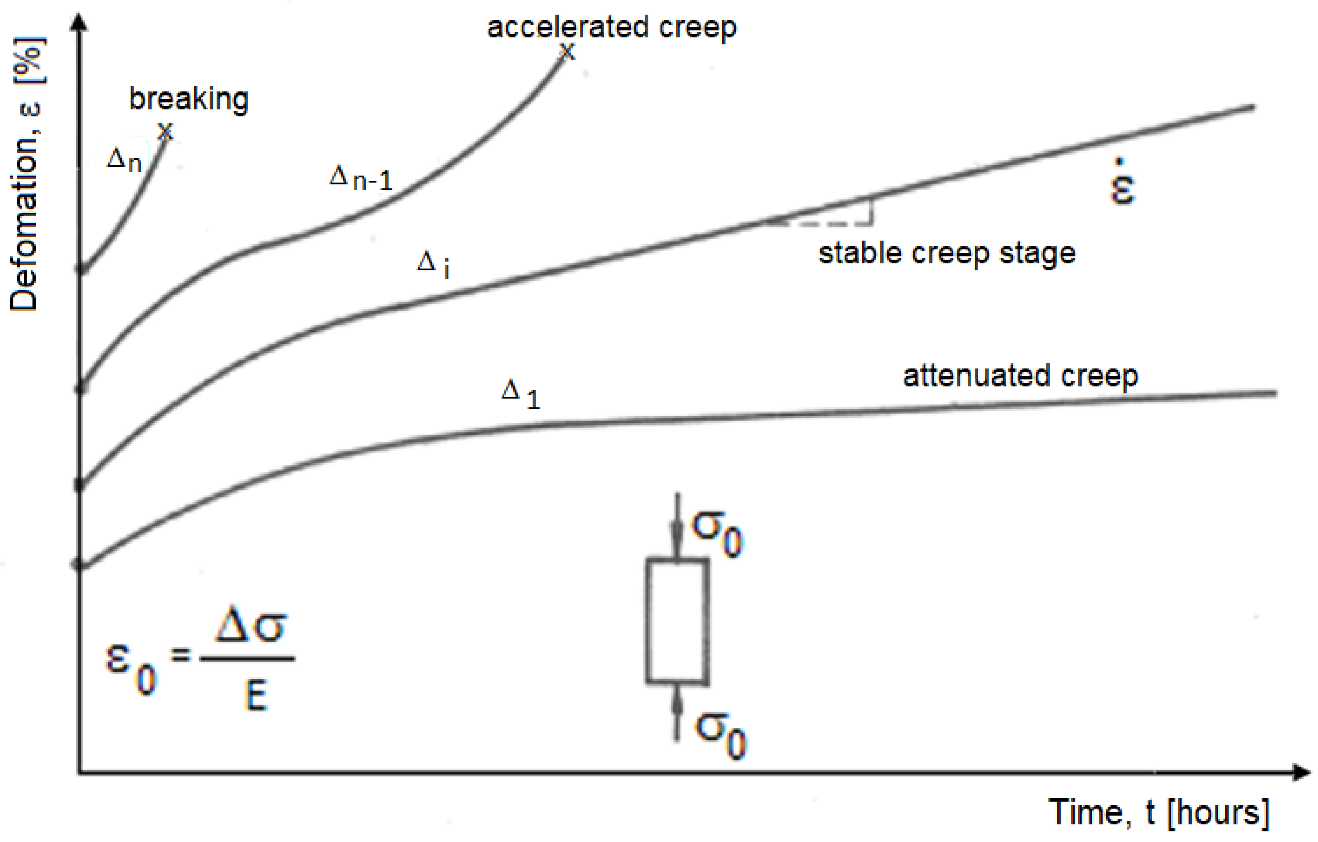
Figure 1. Generalized creep curve ε-t (creep curves obtained for different degrees of stress), marking the three characteristic phases of creep: Δi = (0.2 ÷ 0.95) σrc loading degrees; σrc is uniaxial compressive breaking strength.
Applsci 12 11877 g001
Figure 2. Creep tests of the analyzed andesite subjected to different loads.
Applsci 12 11877 g002
Figure 3. Deformation rate and load degree correlation for the strongly altered analyzed andesite.
Applsci 12 11877 g003
Figure 4. Rheological model for the analyzed strongly metamorphosed andesite.
Applsci 12 11877 g004
Figure 5. This is a figure. Schemes follow the same formatting: (a) deformation in time of the cross gallery; (b) deformation in time of the directional gallery with an arched profile with straight walls; and (c) deformation in time of the directional gallery with a circular profile.
Applsci 12 11877 g005aApplsci 12 11877 g005b
Figure 6. The convergence of directional gallery and arched profile with straight walls.
Applsci 12 11877 g006
Figure 7. Types of deformation as a function of time: 1—linear curve (ambiguity regarding the evolution of stability); 2—damped curve (predictable evolution towards stability); 3—accelerated curve (predictable evolution towards instability and destruction).
Applsci 12 11877 g007
Figure 8. Acceleration of deformation that precede the instability process.
Applsci 12 11877 g008
Figure 9. Different dispersions around the same tendency: (a) case of a continuous deformation and small dispersion; (b) case of a deformation by jump and high dispersion.
Applsci 12 11877 g009
Figure 10. Determining the concavity of the deformation curve by comparing the slopes: (a) accelerated curve—the slope of the straight line (i) is higher than the slope of the reference straight line; (b) damped curve—the slope of the straight line (i) is lower than the slope of the reference straight line.
Applsci 12 11877 g010
Figure 11. Daily alarm: (a) the first alarm level; (b) the second alarm level.
Applsci 12 11877 g011
Figure 12. The evolution in time of the deformations around the analyzed underground works performed in altered andesite: (a) gallery with a circular profile b’-b’’; (b) directional gallery with arched profile with straight walls b’-b’’; (c) cross gallery b’-b’’.
Applsci 12 11877 g012
Figure 13. Deformation curve of the studied andesite obtained by in situ measurements.
Applsci 12 11877 g013
Figure 14. The proposed rheological model.
Applsci 12 11877 g014
Table 1. Data concerning creep tests.
Rock TypeSamples Dimensions (mm)Load Stress, σ0, (MPa)Tests Duration, tMean Breaking Stress, σmed, (MPa)Load Degree, σ0med
dhHoursDays
Altered pyroxene andesite 1424211.5511985028.000.41
14.441198500.51
21.6016870.70
28.00120,51.00
1 Rock samples taken from the experimental sections from Suior mine, Romania.
Table 2. Obtained results from creep tests.
Rock TypeLoad Stress, σ0, (MPa)Stabilization Time, t (Hours)Stable Area, σ0/σcriticRelative Stability Area, σ0/σcriticUnstable Area, σ0/σcritic
Altered pyroxene andesite 111.551650.410.41–0.710.71
14.44
21.60
28.00
1 Rock samples taken from the experimental sections from Suior mine, Romania.
Table 3. The convergence function and the parameter values of this function.
Function TypeCoefficientsCoefficients Values 1
y = 8 m x + b m4800
b1170
1 according to the direction of measurement.
Table 4. Example of calculation for 10 measurements data.
Computing Relations for N = 10 = H0 1u p 1 * p 2 * p 3 * p 4 * p 5 *
p 1 = u = 1 2 p 1 * p 2 = u 2 33 4 = 2 p 2 * p 3 = u 3 293 20 u = 3 5 p 3 * p 4 = u 4 41 2 u 2 + 3861 80 = 12 5 p 4 * p 5 = u 5 155 6 u 3 + 6067 48 u = 10 p 5 * 01−4−12186
13−3−31311
25−1−35−171
372−14−22−14
49642186
γ1652645.1486.8647.800
H 165 2 528 15.444 5 82.368 5 78.000
H j H j 1 8 1 4 6 2 5 5 17 20 5 1 3 4 97 132
1 computing relations for N = 9; N = 11; and N = 12 are shown in Appendix C.
Table 5. Computing scheme of the coefficients.
xyk 1Values of ykSize of
(y+i − y−i)
ValueSize of
(y+i + y−i)
Value
10y−5 y+5 − y−5 --
20y−4 y+4 − y−4 --
30y−3 y+3 − y−3 --
40y−2 y+2 − y−2 --
50y−1 y+1 − y−1 --
60y0-- --
70y+1 --y+1 + y−1
80y+2 --y+2 + y−2
90y+3 --y+3 + y−3
100y+4 --y+4 + y−4
110y+5 --y+5 + y−5
1 for 11 measurements data.
Table 6. Changing the state of the analyzed rocks under the action of the loads and in interaction with the water.
StageStateBehavior 1Flow CriterionEffects that Appear
1Initial stateElastic to elastic–viscous
(Poynting–Thomson model)
-No change in volume
2Weathering stateElastic–plastic α y 1 + y 2 = K Volume increase
3Breaking- α y 1 + y 2 > K
1 altered andesite from Suior mine, Romania.
Publisher’s Note: MDPI stays neutral with regard to jurisdictional claims in published maps and institutional affiliations.