Article

In Silico Evaluation of a Physiological Controller for a Rotary Blood Pump Based on a Sensorless Estimator

by
Mohsen Bakouri
1,2,*,
Ahmad Alassaf
1,
Khaled Alshareef
1,*,
Ibrahim AlMohimeed
1,
Abdulrahman Alqahtani
1,3,
Mohamed Abdelkader Aboamer
1,
Khalid A. Alonazi
4 and
Yousef Alharbi
3
1
Department of Medical Equipment Technology, College of Applied Medical Science, Majmaah University, Al-Majmaah 11952, Saudi Arabia
2
Department of Physics, College of Arts, Fezzan University, Traghen City 71340, Libya
3
Department of Biomedical Technology, College of Applied Medical Sciences, Prince Sattam Bin Abdulaziz University, Al-Kharj 11942, Saudi Arabia
4
Health Services, Ministry of Defense, Riyadh 12426, Saudi Arabia
*
Authors to whom correspondence should be addressed.
Appl. Sci. 2022, 12(22), 11537; https://doi.org/10.3390/app122211537
Submission received: 23 September 2022 / Revised: 24 October 2022 / Accepted: 4 November 2022 / Published: 14 November 2022
(This article belongs to the Section Biomedical Engineering)

Abstract

:
In this study, we present a sensorless, robust, and physiological tracking control method to drive the operational speed of implantable rotary blood pumps (IRBPs) for patients with heart failure (HF). The method used sensorless measurements of the pump flow to track the desired reference flow ( Q r ). A dynamical estimator model was used to estimate the average pump flow ( Q ^ e s t ) based on pulse-width modulation (PWM) signals. A proportional-integral (PI) controller integrated with a fuzzy logic control (FLC) system was developed to automatically adapt the pump flow. The Q r was modeled as a constant and trigonometric function using an elastance function ( E ( t )) to achieve a variation in the metabolic demand. The proposed method was evaluated in silico using a lumped parameter model of the cardiovascular system (CVS) under rest and exercise scenarios. The findings demonstrated that the proposed control system efficiently updated the pump speed of the IRBP to avoid suction or overperfusion. In all scenarios, the numerical results for the left atrium pressure ( P l a ), aortic pressure ( P a o ), and left ventricle pressure ( P l v ) were clinically accepted. The Q ^ e s t accurately tracked the Q r within an error of 0.25 L/min.

1. Introduction

The implementation of modern and sophisticated implantable rotary blood pumps (IRBPs) to treat patients with heart failure (HF) is still under development [1,2]. These devices are utilized to maintain the physiological perfusion of the body on both sides (left and right) of the heart. However, 75% of HF is caused by a predominant left ventricular failure. Therefore, IRBPs are increasingly used for patients with chronic heart disease; they require a complex control technique [3]. The traditional control methods used by these devices have different limitations when adjusting the pump speed under various physiological conditions of the heart [4]. In addition, the implantation of additional sensors is not desired because of thrombi; it also decreases the dependability of the system, raises the cost, and requires constant calibration due to measurement drifts [5].
In the literature, several modern control mechanisms have recently been developed to regulate or track the specified set point of IRBPs [6,7,8]. A few of these methods use sensors such as the flow or pump differential pressure to adapt the pump speed by enhancing the mode of operation [9,10]. Other methods implement sensorless techniques to estimate the heart pump parameters [11,12]. However, to improve the functionality of the settings of the pump and to enhance the reliability of the pump, an advanced physiological controller for IRBPs needs to be implemented [12].
The status of patients with HF can be professionally monitored and controlled using different control methods. For instance, Sadatieh et al. [8] proposed and implemented an extremum-seeking control algorithm to regulate the pump flow based on the amplitude of the limit cycle of the heart. This method was evaluated using an in silico model; the results demonstrated that the control method successfully maintained the mean arterial pressure whilst preventing suction. In a different work, Fetanat et al. [11] developed an intelligent approach to regulate the pump flow in a HeartWare HVAD pump. This method was implemented using a deep convolutional neural network (CNN) to estimate the preload parameter for the patient. Computer simulations were used to evaluate the proposed controller and the results showed that the method accurately regulated the pump speed in a real-time mode. The polynomial control (PC) technique has also been suggested and used by researchers to control IRBPs. In a recent study, the PC was utilized to maintain the average arterial pressure at a particular reference value. This control method regulated the pump differential pressures in each cardiac cycle. The parameters were optimized and calculated using an internal point with minimization. The process was operated under a human heartbeat using an electrocardiogram (ECG) heartbeat algorithm. The method was evaluated using a mathematical simulation of the pediatric cardiovascular system (CVS) and a pediatric pump was applied. The computer simulation results were in agreement with the clinical status of the patient [13].
A classical control method has also been proposed and successfully implemented to drive IRBPs. In this context, a feedback control (FBC) was proposed to predict stochastic models for patients with HF under different physiological conditions. The control algorithm was developed and tested to prevent suction in three scenarios [14]. In addition, a full-state FBC method has also been developed and evaluated. For instance, Bakouri et al. [3] used the FSC technique to regulate the pulsatility of the pump flow. This method was implemented to emulate the Frank–Starling mechanism to prevent suction or overperfusion. The controller was evaluated using the cardiovascular system (CVS) of a lumped parameter model based on two scenarios. The results demonstrated that the controller was able to maintain the physiological perfusion within clinical conditions. In addition, the nonlinear application of fuzzy logic control (FLC) has been developed for RBP systems. For instance, Huang et al. [15] developed a fuzzy control method to drive RBPs based on speed modulations. This technique ensured an adequate perfusion by maintaining the mean aortic pressure whilst increasing the pulse pressure. In a different study, a pulsatility index algorithm was designed for the pump flow based on a proportional-integral (PI) FLC to drive RBPs. The study was numerically evaluated in vitro and in vivo, and the results showed that the controller was able to adequately maintain the body perfusion and prevent suction [16].
Although several modern and classical control methods have been developed and implemented for IRBPs, sensorless control methods for IRBPs are still emerging as essential in offering a long-term alternative treatment for patients with HF. Furthermore, estimating the flow and pressure presents additional features for implementing a physiological controller for these devices [17]. Therefore, this work aimed to design an intelligent physiological controller for IRBPs using a sensorless estimator. The control method was developed and implemented using a proportional-integral (PI) controller associated with an FLC system. The design method assumed that the aortic valve was totally closed to maintain the physiological perfusion in a safe operation mode for the IRBP. Therefore, the controller was utilized as a flow estimator to automatically adjust the physiological demand of the patient by tracking the desired reference flow.

2. Physiological Controller Development

2.1. Software Model of CVS

Figure 1 shows the CVS-IRBP interaction system model utilized to evaluate the proposed control system. This model was developed using MATLAB Simulink tools (The MathWorks Inc., Natick, MA, USA). The model was composed of different numbers of variables that represented lumped parameter blocks. Each parameter was distinguished by its own unique block, such as pressure (P), diodes (D), inertances (L), elastances (E), and resistances (R). The CVS-RBP model consisted of several parts, including pulmonary circulation, systemic circulation, and heart compartments. The motor used as the IRBP in this investigation was a VentrAssist centrifugal pump; this pump belonged to Ventracor Ltd., Sydney, Australia.
In this model, the hydraulic and electrical characteristics of the pump were modeled based on three differential equations. These included the motor windings, motor electromagnetic torque, and the hydraulic pump. These equations could be described as:
-
The electrical motor winding:
v = k ω + R I + L d I d t
where v is the motor terminal voltage, k is the back of the electromotive force, ω is the impeller speed, R is the resistance for the motor winding, I is the motor current, and L is the inductance for the motor winding.
-
The motor electromagnetic torque:
T = J d ω d t + a Q 2 ω + b Q ω 2 + c ω + d ω 3
where T is the electromagnetic torque; Q is the pump flow rate; J is the moment of inertia of the impeller; and a ,   b ,   c , and d are the polynomial coefficients that were obtained by the least squares method using the experimental data under a steady flow condition.
-
The hydraulic pump:
Δ P = e + f Q 3 + g ω 2
where Δ P is the pump differential pressure and e ,   f , and g are constants.
The pressure and volume of each heart compartment were modeled for each chamber based on the cardiac cycle. During this cycle, the elastance function ( E ( t )) was varied according to a linear function during end-systole and an exponential function during end-diastole. The elastance function of this model could be expressed as follows:
E t = s i n 2 π t / T s y s 0                       t < T s y s t T s y s
Here, T s y s is the systolic interval. This model was validated and tested using data from animals in both in vitro and in vivo environments [18,19].

2.2. Flow Estimator Model

An empirical, sensorless, stable, and dynamical model to estimate the average pump flow was developed and validated [20,21]. This model utilized data obtained from dogs in a continuous setting. Two auto-regressive (ARX) models were used for the implementation. The performance of the flow estimator model was evaluated using a variety of hemodynamic parameters to represent different cases of rest, moderation, and exercise of the patient. The model was also assessed using changes in the preload and afterload. The resulting model could be described as follows:
x ^ k + 1 = A x ^ k + B u k + K f y k C x ^ k y ^ k = C x ^ k
where x ^ k is the state estimator vector; K f is the optimal Kelman filter gain; y ^ k is the output of the estimator (average pump flow = ( Q ^ e s t k )); and A , B , and C are compatible dimensional matrices.

2.3. Controller Design

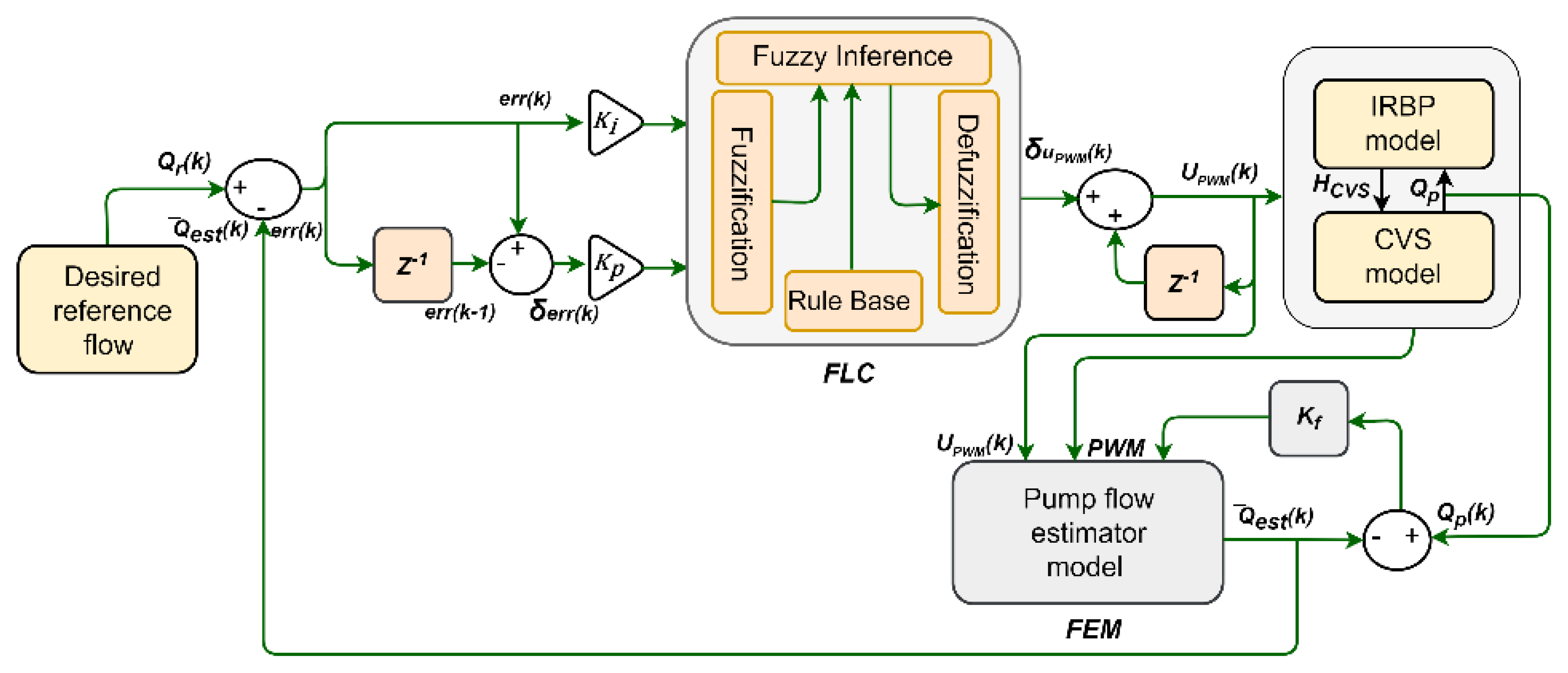
Figure 2 depicts a schematic diagram of the closed-loop control system. This diagram includes a block of the CVS-IRBP, the flow estimator model (FEM), the FLC system, and the desired reference flow ( Q r ). In this work, a hybrid of a fuzzy proportional-integral (PI) control system was proposed. The gain parameters for the PI controller were used to enhance the rise time, overshoot, and settling time where a fuzzy system could adjust the pump flow scaling factor of the PI controller.
This type of controller is known to be more stable with steady-state errors [22]. The FLC system consisted of four components; namely, the rule base, the fuzzy interface, fuzzification, and defuzzification. Within these components, the control index was quantified and acknowledged by the rule base. The control index was then evaluated by the fuzzy interface to enable the correct control input for the plant. Fuzzification was the method used to modify the inputs and defuzzification transformed the right input to the plant based on the fuzzy interface [23].
A fuzzy PI-type control system was employed to track the desired reference flow ( Q r k ). The feedback error ( e r r k ) of the closed-loop control system could be written as follows:
e r r k = Q r k Q ^ e s t k
From Equation (6), we could write:
δ e r r k = e r r k e r r k 1
where δ e r r k is the changes in error.
Equations (6) and (7) were subjected to the PI controller as follows:
δ u P W M k = K p δ e r r k + K i e r r k
where δ u P W M k is the output of the FLC and K p and K i are the proportional and integral gains, respectively.
The control inputs for the fuzzification stage were δ e r r k and e r r k . Figure 3 illustrates the usage of seven asymmetric triangle membership functions to emphasize the property of the error. The input and output labels were written as specified in Table 1. The fuzzy output set was achieved by applying the Mamdani fuzzy rules (Table 2). The defuzzification method was then used to transform the output to a single numerical value as δ u P W M k . The fuzzy toolbox of MATLAB was used for the development of each step (The MathWorks Inc., Natick, MA, USA). All rules were utilized to produce a robust outcome as follows:
γ ε ρ e ,   δ e = min γ ε e ,   γ ρ δ e
γ ε ρ σ e ,   δ e , Δ u P W M = max min γ ε e ,   γ ρ δ e ,   γ σ δ u P W M
where ε and ρ are fuzzy sets for inputs e and δ e , respectively, and σ is a fuzzy set for the output δ u P W M . The defuzzification procedure was carried out using this method and by employing the center of area method, which is described as follows:
δ u P W M = i = 1 n μ σ δ u P W M i δ u P W M i = 1 n μ σ δ u P W M i
where n refers to the number of quantization levels that were included in the output.
The updated speed for the IRBP of the subsequent sample was given by:
u P W M k + 1 = u P W M k + δ u P W M k
where u P W M is the PWM voltage signal, which was the input signal to the IRBP.
To reduce the error between Q r k and Q ^ e s t k , the controller was required to modify the pump speed by changing u P W M k in accordance with the principles of the FLC. To achieve this aim, the controller was required to be able to provide the body with sufficient blood by appropriately driving the pump under a variety of physiological circumstances.

2.4. Desired Reference Flow

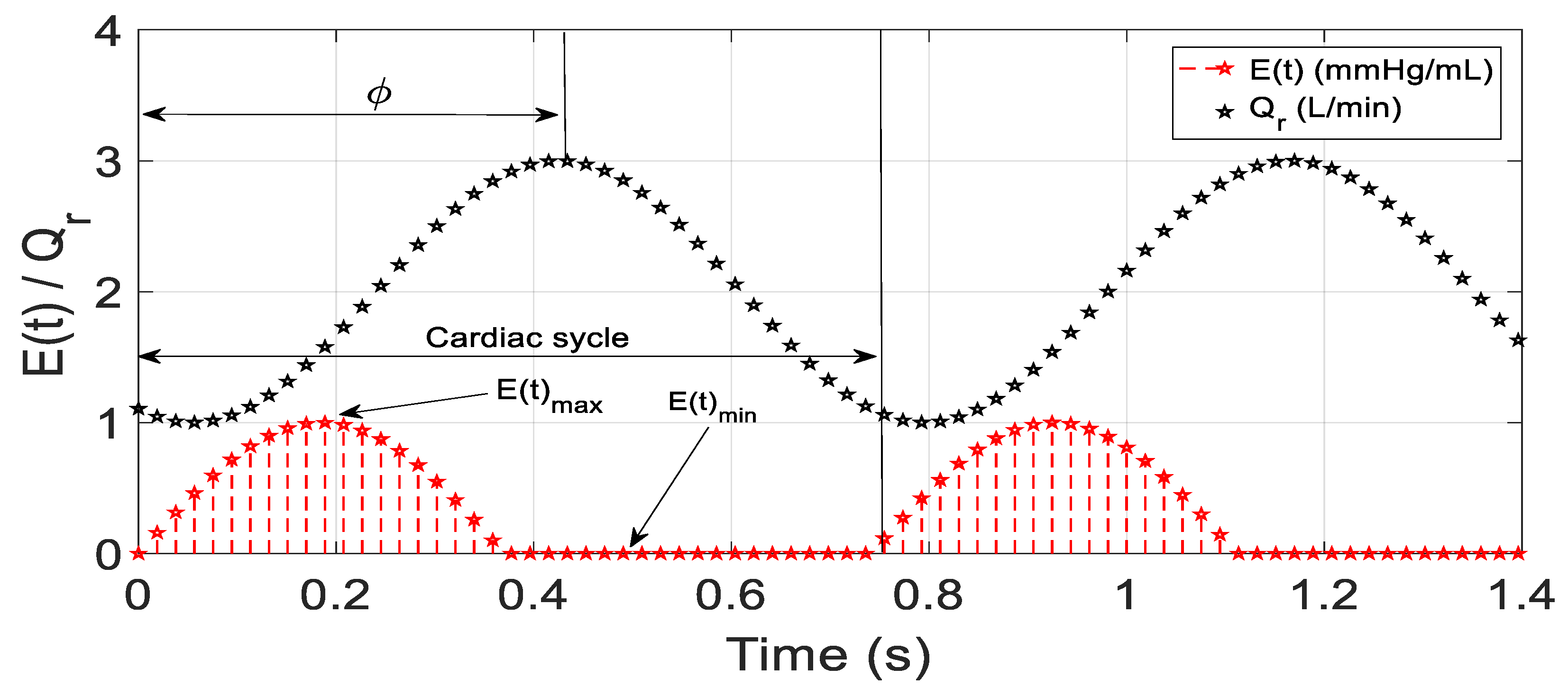
To prevent pulmonary congestion and suction, it is necessary to maintain left atrial pressure ( P l a ) within the usual range for physiological functions. Therefore, to achieve this goal, we assumed that the aortic valve was totally closed. We then modeled the cardiac output as the desired reference flow ( Q r ) using E ( t ), as shown in Equation (4). If the blood flow was greater than the physiological demand, the modeled value of Q r needed to be adjusted. However, Q r needed to be increased to keep the pump flow at the same level if it was lower than the physiological need of the body [24]. Figure 4 depicts the phase shift for sinusoidal Q r in comparison with E ( t ). At this phase shift, Q r was counted as a zero value when the peak value of Q ^ e s t occurred at the end-systole where E ( t ) was at the maximum value.
The following sinusoidal function was used to achieve this mechanism:
Q r = α + β s i n 2 π t / T + φ
where α and β are constants, T is the cardiac cycle, and φ is the phase shift.

2.5. In Silico Protocols

In Table 3, the HF condition was used as the baseline of the system. Based on this table, the left ventricle contractility ( E e s , l v ), right ventricle contractility ( E e s , r v ), systemic vascular resistance ( R s a ), and total blood volume ( V t o t a l ) were varied to generate all scenarios. In the first scenario, we investigated the controller at a constant speed to evaluate the hemodynamic characteristics of the CVS. In this scenario, we turned the controller off and set the IRBP to operate at a constant speed by reducing the V t o t a l by 300 mL at t = 60 s over a period of 10 s. Secondly, the transition from normal to rest was obtained by reducing the V t o t a l by 50% at t = 60 s over a period of 10 s. During this period, Q r linearly decreased from ( 4.5 + 4 s i n 2 π t / T ) to ( 2 + 4 s i n 2 π t / T ). The transition from normal to exercise was then simulated to test the capacity of the controller to offer hemodynamic support for daily activities. During this scenario, E e s , l v and E e s , r v were increased by 20%, and R s a was reduced by 50% over a period of 10 s. During this period, Q r linearly increased from ( 2.5 + 4 s i n 2 π t / T ) to ( 3 + 4 s i n 2 π t / T ). In all simulations, the heart rate equaled the sinusoidal signal frequency and the IRBP flow rate was set to a maximum value of 6 L/min and a minimum value of 2.5 L/min. The PI gains for K p and K i were tuned based on Ziegler–Nichols rules and set to 0.66 and 2.20, respectively.

3. Simulation Results

3.1. Constant Speed Controller

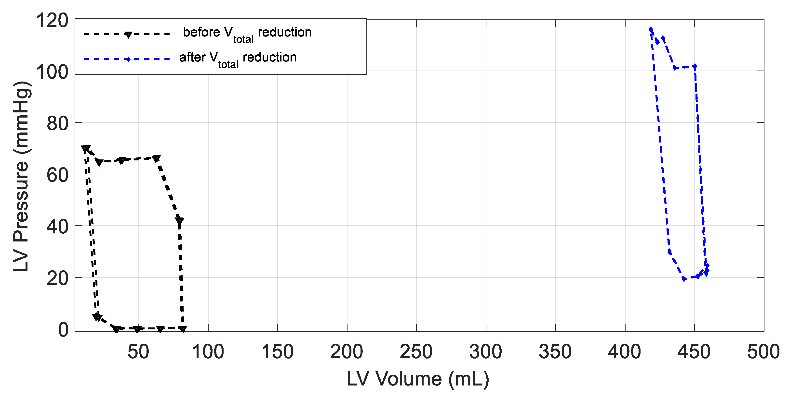
To evaluate the characteristics of the hemodynamic system at a constant speed, we turned the controller off and maintained a constant flow rate for the IRBP. To achieve this scenario, the V t o t a l was reduced by 300 mL at t = 60 s over a period of 10 s. During this period, the stroke volume (SV) decreased due to the reduction in the pump flow. As a result, the pressure–volume loop shifted to the left by about 400 mL, as shown in Figure 5. Therefore, suction could have occurred at any time in this simulation due to the shifted movement volume for the SV reaching 400 mL where no more blood could be pumped by the IRBP. In order to prevent this from happening, we ensured that the desired reference signal was configured to reduce the average pumping rate as a reaction to a reduction in the total blood volume or to re-operate the controller.

3.2. Changes in Patient Parameters to Demonstrate a Relaxation Test

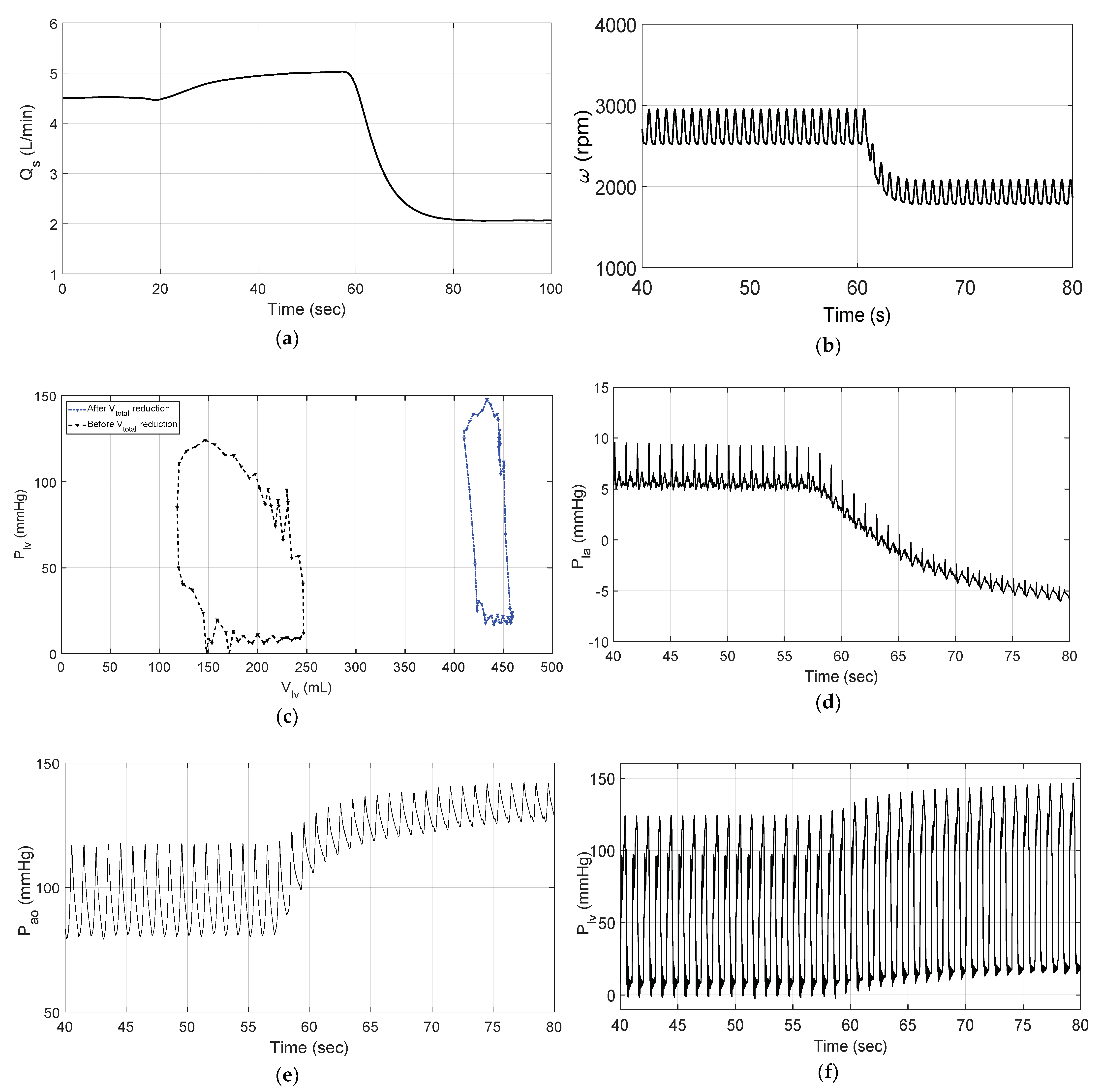
Figure 6 depicts the waveforms of the systematic flow ( Q s ), IRBP speed ( ω t ), stroke volume (SV), left atrium pressure ( P l a ), aortic pressure ( P a o ), left ventricle pressure ( P l v ), estimated flow ( Q ^ e s t ) vs. the desired reference flow ( Q r ), and the correlation between the estimated flow ( Q ^ e s t ) and the actual flow ( Q p ) generated by the CVS model in the relaxation scenario. When suddenly decreasing the V t o t a l at 60 s for a period of 10 s, the closed-loop control system automatically activated to track the changes in Q r from ( 4.5 + 4 s i n 2 π t / T ) to ( 2 + 4 s i n 2 π t / T ). During this period, the desired reference signal decreased over an interval of 10 s.
During the relaxation test, the controller responded to the decrease in the systematic flow from 4.5 L/m to 2 L/min (Figure 6a) by reducing the pump speed from 2950 rpm to 2100 rpm (Figure 6b). Based on that, the stroke volume of the LV decreased due to the reduction in V t o t a l . These changes were associated with the shift to the left of the LV volume–pressure loop by 300 mL (Figure 6c). As a result, the IRBP successfully reduced P l a and increased P a o and P l v as fluctuation signals (Figure 6d, Figure 6e and Figure 6f, respectively).
The results also demonstrated that Q ^ e s t accurately tracked Q r within an error of 0.25 L/min (Figure 6g). Moreover, the correlation between Q ^ e s t and Q p was significantly high; the slope was 1.13 for the linear regression, the mean absolute error e r r o r m e a n = 0.2637 , and the correlation coefficient R 2 = 0.9949 .

3.3. Changes in Patient Parameters to Demonstrate an Exercise Test

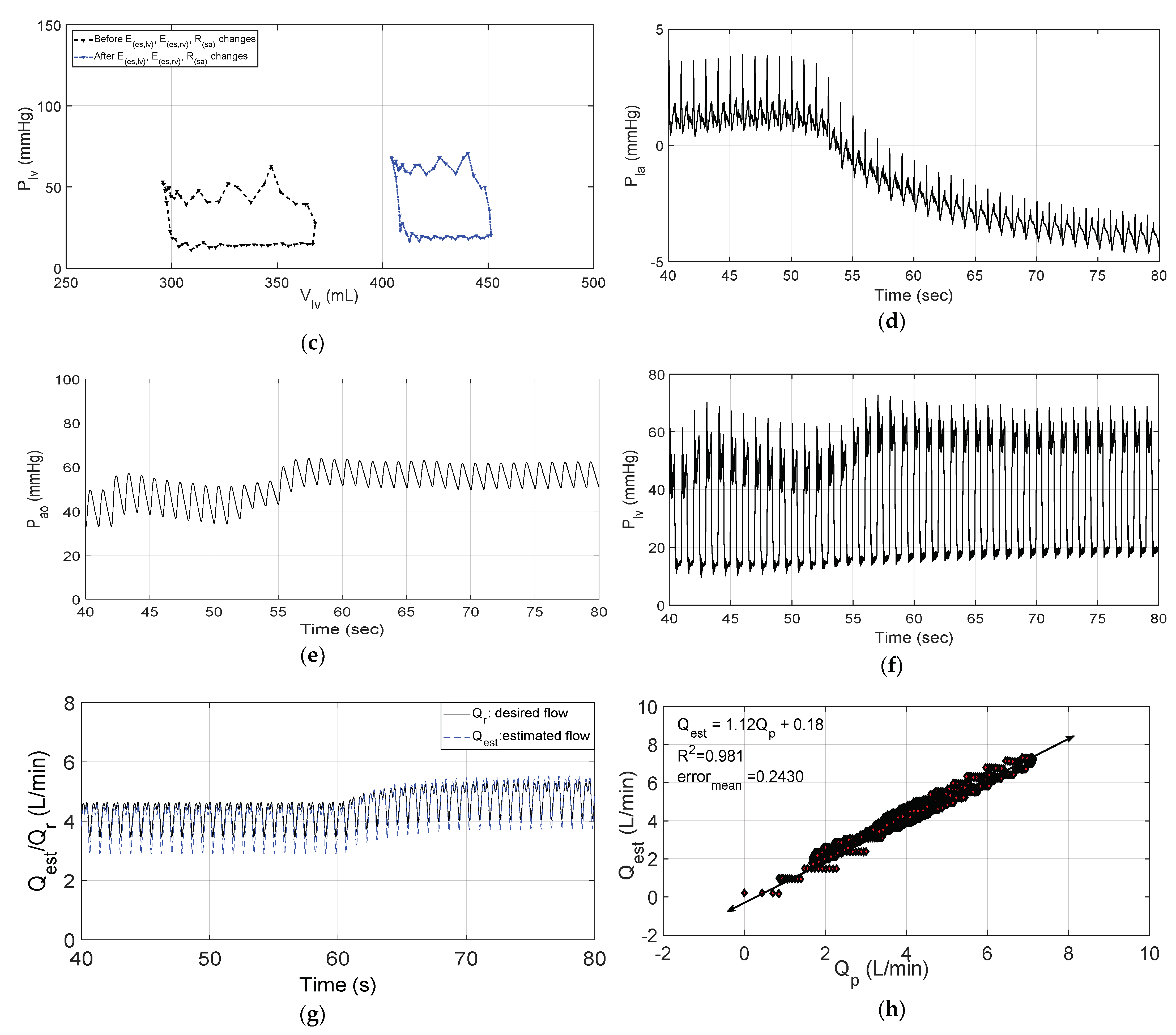
Figure 7 illustrates the waveforms of the model simulation during the changes in parameters for the CVS in the exercise test. In this test, E e s , l v and E e s , r v were increased by 20% and R s a was reduced by 50% at 60 s over a period of 10 s. During this period, the closed-loop control system automatically activated to linearly track the increase in Q r from ( 3 + 4 s i n 2 π t / T ) to ( 3 + 4 s i n 2 π t / T ).
During the exercise test, the controller responded to changes in the systematic flow from the initial value of 3.5 L/m to 2.8 L/min (Figure 7a) by increasing the pump speed from 2800 rpm to 3500 rpm (Figure 7b). These changes were associated with a decrease in the size of the stroke volume and shifted to the left by 210 mL (Figure 7c). As a result, the IRBP successfully reduced P l a and increased P a o and P l v as fluctuation signals (Figure 7d, Figure 7e and Figure 7f, respectively).
The results also demonstrated that Q ^ e s t accurately tracked Q r within an error of 0.25 L/min (Figure 7g). Moreover, the correlation between Q ^ e s t and Q p was significantly high; the slope was 1.12 for the linear regression, the mean absolute error e r r o r m e a n = 0.2430 , and R 2 = 0.981 .
The hemodynamical results in healthy humans and the simulation of both scenarios (rest and exercise) are shown in Table 4.

4. Discussion

Implantable rotary blood pumps (IRBPs) are considered to be one of the most significant advancements in modern technology and have been used to improve the quality of life for heart failure (HF) patients. However, the implementation of control strategies for these devices is still under development. These devices need to manage the physiological requirements of the patient by continuous monitoring to meet the appropriate response by the IRBP. The broad aim of this work was to develop a sensorless physiological controller to adjust the pump flow in accordance with the demand of the body.
Generally, the flow rate values in a human body for a healthy person range from 4.4 to 5.5 L/min. These values are significantly reduced for HF patients, with contents of 1.5 to 2 L/min. In this work, the pump flow rate variable was successfully used as a hemodynamic parameter to drive an IRBP. The results indicated that the fuzzy PI-type control system offered a robust method to maintain the CVS variables for patients with HF. As shown in Figure 6 and Figure 7, the controller robustly tracked the desired reference flow within a minimal and clinically accepted value (0.25 L/min). As a result, the control system automatically adjusted the pump speed to prevent suction (>1.5 L/min) or overperfusion (<7.5 L/min). In both scenarios, the linear regression analysis between the estimated and actual flow was highly correlated and the slopes were close to unity. The results also showed that the mean absolute error between the estimated and actual flow converged to zero (Figure 6h and Figure 7h).
To accurately automate the pump speed and physiological perfusion for patients with HF, we assumed that the aortic valve was closed and that the total blood passed to the aorta through the IRBP. By employing these assumptions, our design method was able to maintain the stroke volume of patients with HF within a minimal range ( 350   m L). In comparison, the simulation results showed that ventricular suction could occur at any time due to the stroke volume reaching 400 mL at a constant speed. However, these assumptions cannot be applied to all patients due to pulsatility and the useful amount of blood that passes through the aorta. Nonetheless, controlling the aortic valve function with a safe operating mode for an IRBP to maintain the physiological perfusion is still a preliminary issue [25]. For this reason, several researchers have developed physiological control methods based on aortic valves that might be assumed to be closed [21]. For instance, in 2019, Petukhov et al. [26] proposed a novel control method for a full and a partial support to adjust the pump flow of IRBPs. The method was successfully implemented and evaluated based on a pump flow estimation and aortic valve state detection in a changing heart rate (HR) and contractility.
Various control mechanisms have been developed and implemented based on multiple hemodynamic factors. These factors use intrinsic pump parameters based on the use of the linear functions of a CVS model. It might be challenging to use this approach when simulating patients. For example, a linear model may not be consistent across a group of patients. This may lead to simulation inaccuracy and an inconsistent quantization performance. Furthermore, the pump flow derived from intrinsic pump feedback signals as the total flow to humans may increase the estimation error [27]. However, in this study, the flow estimator model was stable and guaranteed the performance of the controller in providing significant tracking, as shown in Figure 6h and Figure 7h.
This work was designed based on an estimated pump flow parameter. The results in Table 4 illustrate that the CVS hemodynamic variables varied within acceptable clinical conditions. However, several researchers have used different variables for controlling IRBPs. These variables may include an afterload or aortic pressure, arterial pulsatility, suction detection, and he heart rate. We believe that the pump flow parameter is the most significant parameter to achieve a physiological controller. For example, an afterload or aortic pressure are essential parameters to be estimated or measured before the ventricles can push blood out of their respective semilunar valves. However, this parameter is not widely used to drive IRBPs [28].
Our results also showed that the controller was able to prevent suction by decreasing the left atrial pressure. As a result, the controller maintained a pump flow with a minimum value of 2 L/min in relaxation and a minimum value of 2.8 L/min in exercise conditions. A suction detection variable has also been used to control rotary blood pumps. This variable usually leads to a ventricular collapse when an IRBP works at high speed. A recent study was conducted by Peng et al. [29] to detect ventricular suction for the rotary mechanism of an IRBP. In this study, intrinsic pump parameters were used in addition to a model that recognized suction without the use of sensors. The proposed method was evaluated using two pump states: ventricular suction and nonventricular suction. In 2019, Son et al. [30] implemented a feedback control strategy using a suction prevention unit integrated with pulsatility. The performance of the method and the suction prevention were evaluated to demonstrate the efficiency and feasibility of the designed strategy.
This study had several limitations. Unlike the previous study [31], this work did not employ the mechanism of a Frank–Starling-like controller. This mechanism guarantees that the preload parameter (left ventricle end-diastolic volume) is utilized. This parameter has been proven to be a significant parameter for obtaining and implementing a physiological controller for patients with HF [32]. In addition, this study did not include a simulation of the baroreflex, which may have impacted the results and CVS hemodynamics.
In the future, this study could be extended to evaluate and validate the proposed control system in mock circulation loops. In this validation, postural changes and Valsalva maneuvers could be simulated at realistic rates of change in physical mock loop resistance and compliance.

5. Conclusions

In this study, a sensorless physiological control method for an IRBP was developed and implemented to maintain the physiological perfusion of patients with HF. The technique used an estimator model to estimate the average pump flow. A fuzzy PI-type control system was utilized to adjust the speed of the IRBP by tracking the desired flow. The desired pump flow was modeled as a cardiac output using an elastance function ( E ( t )).
The proposed method was evaluated in silico using a lumped parameter model of the CVS-RBP with MATLAB software. The parameters of this model were utilized to replicate the conditions of patients with HF based on clinical data. The method was examined under two different physiological scenarios ranging between rest and exercise. In each scenario, the CVS parameters were changed by adjusting E e s , l v , E e s , r v , R s a , and V t o t a l .
The hemodynamic results showed that the proposed control method accurately tracked the desired reference flow within a minimum value of 0.25 L/min. The system also demonstrated that the correlation between the estimated and actual flow was close to unity. In addition, the system reported that all hemodynamic parameters, including P l a , P a o , P l v , and Q p , were appropriate for clinical use. The findings showed that the design method successfully prevented ventricular collapse and excessive blood flow.

Author Contributions

Conceptualization, M.B.; methodology, M.B., and A.A. (Ahmad Alassaf); software, M.B., and A.A. (Ahmad Alassaf), K.A., and Y.A.; validation, M.B., and A.A. (Ahmad Alassaf), A.A. (Abdulrahman Alqahtani), and M.A.A.; formal analysis, M.B., A.A. (Abdulrahman Alqahtani), I.A., M.A.A., K.A.A., and Y.A.; visualization, all authors; writing—original draft preparation, all authors. All authors have read and agreed to the published version of the manuscript.

Funding

This research was funded by the deputyship for Research and Innovation, Ministry of Education, Saudi Arabia, grant number IFP-2020-43.

Institutional Review Board Statement

Not applicable.

Informed Consent Statement

Not applicable.

Data Availability Statement

Not applicable.

Acknowledgments

The authors extend their appreciation to the deputyship for Research and Innovation, Ministry of Education in Saudi Arabia for funding this research work through project number IFP-2020-43.

Conflicts of Interest

The authors declare no conflict of interest.

Abbreviations

CVSCardiovascular system
HFHeart failure
ARXAuto-regressive
IRBPImplantable rotary blood pump
FLCFuzzy logic control
PIProportional-integral
FEMFlow estimator model
PWMPulse-width modulation
Q r Desired reference flow
Q ^ e s t Estimated average pump flow
P l a Left atrium pressure
P a o Aortic pressure
P l v Left ventricle pressure
E ( t )Elastance function
V t o t a l Total blood volume
E e s , l v Left ventricle contractility
E e s , r v Right ventricle contractility
R s a Systemic vascular resistance
Q s Systematic flow
Q p Actual flow
V l v Left ventricle volume
P l v Left ventricle pressure
SVStroke volume

References

  1. Wang, Y.; Shen, P.; Zheng, M.; Fu, P.; Liu, L.; Wang, J.; Yuan, L. Influence of Impeller Speed Patterns on Hemodynamic Characteristics and Hemolysis of the Blood Pump. Appl. Sci. 2019, 9, 4689. [Google Scholar] [CrossRef] [Green Version]
  2. Wu, P. Recent advances in the application of computational fluid dynamics in the development of rotary blood pumps. Med. Nov. Technol. Devices 2022, 28, 100177. [Google Scholar] [CrossRef]
  3. Bakouri, M. Physiological Control Law for Rotary Blood Pumps with Full-State Feedback Method. Appl. Sci. 2019, 9, 4593. [Google Scholar] [CrossRef] [Green Version]
  4. Jing, T.; Xin, T.; Wang, F.; Zhang, Z.; Zhou, L. Control Strategy Design of a Microblood Pump Based on Heart-Rate Feedback. Micromachines 2022, 13, 358. [Google Scholar] [CrossRef]
  5. Elenkov, M.; Lukitsch, B.; Ecker, P.; Janeczek, C.; Harasek, M.; Gföhler, M. Non-parametric dynamical estimation of blood flow rate, pressure difference and viscosity for a miniaturized blood pump. Int. J. Artif. Organs 2022, 45, 207–215. [Google Scholar] [CrossRef]
  6. Cysyk, J.; Jhun, C.S.; Newswanger, R.; Pae, W.; Izer, J.; Flory, H.; Reibson, J. Weiss, W.; Rosenberg, G. Vivo Evaluation of a Physiologic Control System for Rotary Blood Pumps Based on the Left Ventricular Pressure-Volume Loop. ASAIO J. 2022, 5, 791–799. [Google Scholar] [CrossRef]
  7. Ogawa, D.; Kobayashi, S.; Yamazaki, K.; Motomura, T.; Nishimura, T.; Shimamura, J.; Tsukiya, T.; Mizuno, T.; Takewa, Y.; Tatsumi, E.; et al. Evaluation of cardiac beat synchronization control for a rotary blood pump on valvular regurgitation with a mathematical model. Artif. Organs 2020, 45, 124–134. [Google Scholar] [CrossRef] [PubMed]
  8. Sadatieh, S.; Dehghani, M.; Mohammadi, M.; Boostani, R. Extremum-seeking control of left ventricular assist device to maximize the cardiac output and prevent suction. Chaos Solitons Fractals 2021, 148, 111013. [Google Scholar] [CrossRef]
  9. Liang, L.; Qin, K.; El-Baz, A.S.; Roussel, T.J.; Sethu, P.; Giridharan, G.A.; Wang, Y. A Flow Sensor-Based Suction-Index Control Strategy for Rotary Left Ventricular Assist Devices. Sensors 2021, 21, 6890. [Google Scholar] [CrossRef]
  10. Yun, Z.; Li, K.; Jiang, H.; Tang, X. A Composite Flexible Sensor for Direct Ventricular Assist Device. Sensors 2022, 22, 2607. [Google Scholar] [CrossRef] [PubMed]
  11. Fetanat, M.; Stevens, M.; Hayward, C.; Lovell, N. Adaptive sensorless control of LVAD using deep convolutional neural network. J. Heart Lung Transplant. 2021, 40, S172. [Google Scholar] [CrossRef]
  12. Bakouri, M.; Alassaf, A.; Alshareef, K.; Abdelsalam, S.; Ismail, H.F.; Ganoun, A.; Alomari, A.-H. An Optimal H-Infinity Controller for Left Ventricular Assist Devices Based on a Starling-like Controller: A Simulation Study. Mathematics 2022, 10, 731. [Google Scholar] [CrossRef]
  13. Cordeiro, T.D.; Sousa, D.L.; Cestari, I.A.; Lima, A.M.N. A physiological control system for ECG-synchronized pulsatile pediatric ventricular assist devices. Biomed. Signal Process. Control 2020, 57, 101752. [Google Scholar] [CrossRef]
  14. Son, J.; Du, D.; Du, Y. Modelling and control of a failing heart managed by a left ventricular assist device. Biocybern. Biomed. Eng. 2020, 40, 559–573. [Google Scholar] [CrossRef]
  15. Huang, F.; Ruan, X.; Fu, X. Pulse-Pressure–Enhancing Controller for Better Physiologic Perfusion of Rotary Blood Pumps Based on Speed Modulation. ASAIO J. 2014, 60, 269–279. [Google Scholar] [CrossRef]
  16. Choi, S.; Antaki, J.E.; Boston, R.; Thomas, D. A sensorless approach to control of a turbodynamic left ventricular assist system. IEEE Trans. Control Syst. Technol. 2001, 9, 473–482. [Google Scholar] [CrossRef] [Green Version]
  17. Wang, Y.; Koenig, S.C.; Wu, Z.J.; Slaughter, M.S.; Giridharan, G.A. Sensorless physiologic control, suction prevention, and flow balancing algorithm for rotary biventricular assist devices. IEEE Trans. Control Syst. Technol. 2017, 27, 717–729. [Google Scholar] [CrossRef]
  18. Lim, E.; Dokos, S.; Cloherty, S.L.; Salamonsen, R.F.; Mason, D.G.; Reizes, J.A.; Lovell, N.H. Parameter-Optimized Model of Cardiovascular–Rotary Blood Pump Interactions. IEEE Trans. Biomed. Eng. 2009, 57, 254–266. [Google Scholar] [CrossRef]
  19. Lim, E.; Dokos, S.; Salamonsen, R.F.; Rosenfeldt, F.L.; Ayre, P.J.; Lovell, N.H. Numerical optimization studies of cardiovascular–rotary blood pump interaction. Artif. Organs 2012, 36, E110–E124. [Google Scholar] [CrossRef] [PubMed]
  20. Bakouri, M.A.; Savkin, A.V.; Alomari, A.H. Nonlinear modelling and control of left ventricular assist device. Electron. Lett. 2015, 51, 613–615. [Google Scholar] [CrossRef]
  21. Bakouri, M.A.; Salamonsen, R.F.; Savkin, A.V.; AlOmari, A.H.; Lim, E.; Lovell, N.H. A Sliding Mode-Based Starling-Like Controller for Implantable Rotary Blood Pumps. Artif. Organs 2014, 38, 587–593. [Google Scholar] [CrossRef] [PubMed]
  22. Nise, N.S. Control Systems Engineering; John Wiley & Sons: Hoboken, NJ, USA, 2020. [Google Scholar]
  23. Jayetileke, H.R.; de Mel, W.R.; Mukhopadhyay, S.C. Real-Time Metaheuristic Algorithm for Dynamic Fuzzification, De-Fuzzification and Fuzzy Reasoning Processes. Appl. Sci. 2022, 12, 8242. [Google Scholar] [CrossRef]
  24. Lim, E.; Alomari, A.H.; Savkin, A.V.; Dokos, S.; Fraser, J.F.; Timms, D.L.; Mason, D.G.; Lovell, N.H. A method for control of an implantable rotary blood pump for heart failure patients using noninvasive measurements. Artif. Organs 2011, 35, E174–E180. [Google Scholar] [CrossRef] [PubMed]
  25. Bozkurt, S. Physiologic outcome of varying speed rotary blood pump support algorithms: A review study. Australas. Phys. Eng. Sci. Med. 2016, 39, 13–28. [Google Scholar] [CrossRef]
  26. Petukhov, D.; Korn, L.; Walter, M.; Telyshev, D. A novel control method for rotary blood pumps as left ventricular assist device utilizing aortic valve state detection. BioMed Res. Int. 2019, 11, 2019. [Google Scholar] [CrossRef] [Green Version]
  27. Fetanat, M.; Stevens, M.; Hayward, C.; Lovell, N.H. A physiological control system for an implantable heart pump that accommodates for interpatient and intrapatient variations. IEEE Trans. Biomed. Eng. 2019, 67, 1167–1175. [Google Scholar] [CrossRef] [Green Version]
  28. Alomari, A.H.; Savkin, A.V.; Stevens, M.; Mason, D.G.; Timms, D.L.; Salamonsen, R.F.; Lovell, N.H. Developments in control systems for rotary left ventricular assist devices for heart failure patients: A review. Physiol. Meas. 2013, 34, R1. [Google Scholar] [CrossRef]
  29. Peng, J.; Lu, A.; Wang, Y. Modeling of a New Sensorless Suction Detection System for the Rotary Left Ventricular Assist Device. In Proceedings of the 9th International Conference in Information Technology Medicine Education ITME 2018, Hangzhou, China, 19–21 October 2018. [Google Scholar]
  30. Son, J.; Du, D.; Du, Y. Feedback control of rotary blood pump for preventing left ventricular suction. In Proceedings of the America Control Conference 2019, Philadelphia, PA, USA, 9–13 March 2019; pp. 5426–5431. [Google Scholar]
  31. Bakouri, M.; Alassaf, A.; Alshareef, K.; Smida, A.; AlMohimeed, I.; Alqahtani, A.; Aboamer, M.A.; Alharbi, Y. A Feasible Method to Control Left Ventricular Assist Devices for Heart Failure Patients: A Numerical Study. Mathematics 2022, 10, 2251. [Google Scholar] [CrossRef]
  32. Salamonsen, R.F.; Lim, E.; Gaddum, E.; Alomari, A.H.; Gregory, S.D.; Stevens, M.; Mason, D.G.; Fraser, J.F.; Timms, D.; Karunanithi, M.K.; et al. Theoretical foundations of a Starling-like controller for rotary blood pumps. Artif. Organs 2012, 36, 787–796. [Google Scholar] [CrossRef]
Figure 1. Cardiovascular system CVS-IRBP interaction model. M: pump motor; P : pressure; D : diodes; L : inertances; E : elastances; R : resistances; L i n : inlet cannulae inertances; L o u t : outlet cannulae inertances; R s u c : suction resistance; R i n : inlet cannulae resistances ;   R o u t : outlet cannulae resistances.
Applsci 12 11537 g001
Figure 2. Schematic representation of the proposed system. CVS: cardiovascular system; IRBP: implantable rotary blood pump; FLC: fuzzy logic control; H c v s : differential pressure; FEM: flow estimator model; Q r k : desired reference flow; Q p k : actual pump flow; Q ^ e s t : estimated average pump flow; e r r k : error; δ e r r k : difference in error; PWM: pulse-width modulation; U P W M : PWM voltage signal; K p : proportional gain; K i : integral gain; K f : Kelman filter gain.
Applsci 12 11537 g002
Figure 3. Variables of membership function: (a) first input (e); (b) second input δ e ; (c) output ( u P W M ).
Applsci 12 11537 g003
Figure 4. Phase shift for sinusoidal desired reference flow ( Q r ) in comparison with elastance function ( E ( t )).
Applsci 12 11537 g004
Figure 5. Hemodynamic characteristics for a controller at constant speed.
Applsci 12 11537 g005
Figure 6. Results in relaxation test; (a) systematic flow ( Q s ); (b) IRBP speed ( ω t ); (c) stroke volume (SV); (d) left atrium pressure ( P l a ); (e) aortic pressure ( P a o ); (f) left ventricle pressure ( P l v ); (g) estimated flow ( Q ^ e s t ) vs. desired reference flow ( Q r ); (h) correlation between estimated flow ( Q ^ e s t ) and actual flow ( Q p ).
Applsci 12 11537 g006aApplsci 12 11537 g006b
Figure 7. Results in exercise test; (a) systematic flow ( Q s ); (b) IRBP speed ( ω t ); (c) stroke volume (SV); (d) left atrium pressure ( P l a ); (e) aortic pressure ( P a o ); (f) left ventricle pressure ( P l v ), (g) estimated flow ( Q ^ e s t ) vs. desired reference flow ( Q r ); (h) correlation between estimated flow ( Q ^ e s t ) and actual flow ( Q p ).
Applsci 12 11537 g007aApplsci 12 11537 g007b
Table 1. The input and output labels of FLC.
NG3NG2NG1ZPO1PO2PO3
Large
negative
Medium
negative
Small
negative
ZeroSmall
positive
Medium
positive
Large
positive
Table 2. Rules of FLC.
δ e NG3NG2NG1ZPO1PO2PO3
e
NG3NG3NG3NG3NG2NG1NG1Z
NG2NG3NG3NG2NG1NG1ZPO1
NG1NG3NG2NG1NG1ZPO1PO1
ZNG2NG1NG1ZPO1PO1PO2
PO1NG1NG1ZPO1PO1PO2PO3
PO2NG1ZPO1PO1PO2PO3PO3
PO3ZPO1PO1PO2PO3PO3PO3
Table 3. Baseline of CVS model.
ParameterHealthy CaseHeart Failure Case
V t o t a l 5300 mL5800 mL
E e s , l v 3.54 mm Hg/mL0.71 mm Hg/mL
E e s , r v 1.75 mm Hg/mL0.53 mm Hg/mL
R s a 0.74 mm Hg·s/mL1.11 mm Hg·s/mL
Table 4. CVS variables from the simulation results.
ParametersHealthyHF and IRBP
RestExercise
P l a (mmHg)251510
P a o (mmHg)12010080
P l v (mmHg)1209580
Q p (L/min)5.522.8
Publisher’s Note: MDPI stays neutral with regard to jurisdictional claims in published maps and institutional affiliations.