1. Introduction
Avionics systems are the sum of all electronic systems in an aircraft, including communication, navigation, display, radar, sensor, airborne network, and flight management systems [
1,
2]. With the rapid development of microelectronic and computer technology, new technologies of avionics systems are constantly emerging [
3,
4], the structure and function of avionics systems are becoming increasingly complex, with their design moving towards integration, modularization, generalization, and intelligence, which have led to a breakthrough in the function, performance, reliability, maintainability, supportability, testability, and comprehensive efficiency of avionics systems [
4,
5]. Due to this increasing complexity, the traditional aviation chimney development process has been unable to meet the development requirements of large-scale complex avionics systems in terms of time, cost, and reusability [
6]. In turn, this exacerbates the conflict between pursuing better functionality, higher reliability, better adaptability, and stronger survivability and making all of this affordable [
7,
8]. Therefore, avionics systems are becoming ever more important, and they determine the overall performance of the aircraft to a large extent [
9,
10].
The simulation and verification of avionics systems have become the key technology of the development of avionics systems, with the simulation and verification of the system also being a complex system of engineering [
11]. The simulation and verification platform of avionics systems is a real-time scheduling platform that integrates various resources in the verification environment and realizes the coordinated operation of resources in avionics systems. It is used to provide underlying support for various functions of the simulation and verification systems [
12,
13]. The simulation and verification of avionics systems mainly use the simulation and verification platform to gradually integrate all parts of the internal structure of these systems (models or physical objects, including real airborne equipment, simulation equipment, virtual equipment, or simple models) according to the logical and physical architecture of system design, so that they can operate dynamically in various external environments. This allows for verification and testing of whether the system as a whole works properly, and whether it meets the functions and performance required by the design, thereby reducing the high costs and risks that flight tests may incur, which plays an irreplaceable role in the research of increasingly complex avionics systems [
14,
15,
16].
However, there are many serious problems in the simulation and verification of traditional avionics systems, especially in the aspects of scheduling, communication, and management. Therefore, the main problems can be listed in the following four aspects: First, avionics systems usually require unique technical requirements and individual suppliers, which provide optimal services for the aviation industry. However, this development process has some undesirable side effects, including long production cycles, tedious improvement processes, and a lack of hardware and software reuse between different aircraft platforms, which results in the design of proprietary platforms [
12]. Second, the simulation and verification environment of avionics systems is a complex project, which not only has a complex structure and needs a variety of models, but also its operation is more convoluted, requiring the cooperative work of various models to bring the simulation and verification environment closer to the real machine [
17]. Third, avionics systems require frequent data exchange and high real-time requirements. The traditional manual solution to the problem of data exchange between input and output has resulted in a great workload on the construction of simulation platforms in the past [
18,
19]. Fourthly, the research and development of real equipment are constantly being upgraded and improved, which has also brought a lot of changes in data interfaces [
19]. The emergence of complex task equipment and electronic systems has increased the cost and time of integrating new hardware and software into avionics systems [
20]. There is an urgent need for an integrated platform to manage and schedule large and scattered hardware and software, thereby reducing development and verification costs [
20,
21].
In this paper, faced with the aforementioned problems, a simulation and verification platform for avionics systems based on the FACE architecture is designed by using component technology and memory database technology. The main contributions are as follows:
1. This paper proposes a general architecture for avionics systems based on the FACE architecture which contributes to realizing the reuse and portability of the components, thus realizing the sharing of avionics resources and plug-and-play modules. It lays a foundation for the simulation and verification of avionics systems.
2. This paper proposes a simulation and verification platform for avionics systems which consists of scheduling management, communication management, and configuration management. It not only realizes the registration, management, and scheduling of component models, but also ensures the consistency and integrity of the interactive data, and also avoids the trouble of manually changing operation information.
The rest of the paper is organized as follows. First,
Section 2 summarizes the related work of simulation and verification for avionics systems. Next,
Section 3 introduces the design and implementation of the simulation and verification platform. In addition,
Section 4 introduces the experimental results and software testing on the simulation and verification platform for avionics systems. Finally,
Section 5 summarizes our work.
2. Related Work
With the development of avionics technology, a large number of tests are needed on the avionics platform, but it is very difficult to study the test results on real avionics systems. In order to reduce energy consumption, service providers need to simulate and analyze the results [
22]. At the same time, utilizing the real-time simulation computer, the mathematical model of each system, and the interface equipment, the external environment for the physical avionics systems is built under real operational conditions [
23], while the function and performance of avionics systems are comprehensively verified, so as to reduce the high cost and risk that flight testing may bring [
12].
The purpose of the design and implementation of the simulation and verification platform for avionics systems is to carry out various flight scenarios and flight simulation experiments, dynamically check the interaction logic of avionics systems, verify whether the system design is reasonable, expose the internal defects of cooperative work, and increase the maturity of the design and integration of avionics systems [
24]. This testing of avionics simulation components or modules helps ensure the success of the entire avionics systems [
25,
26].
At present, common simulation and verification platforms include ITB, ADS2, and VAIS [
27,
28]. ITB (Interface Test Bench), also known as the I/O interface test system, developed by Beijing Hengrun Technology Company, contains the functions of automatic testing, data definition, data playback, data monitoring, and so on. It has been successfully applied to the comprehensive simulation testing of missile guidance systems and the factory testing of airborne equipment, but its price is relatively low. ADS2 (Avionics Development System 2) is a software and hardware integration system developed by TechSAT GmbH Company in Germany. It has been successfully applied to the test platform for avionics systems of the Airbus Company. Based on the ADS2 system, the software environment and hardware platform of complex avionics systems can be quickly built, so as to realize the simulation, integration, and verification of the system. Its disadvantages are high cost and high operation requirements [
28]. VAIS (Virtual Aircraft Integration System) is a virtual aircraft integration system of General Electric Corporation of America. It can simulate the simultaneous testing of multiple aircraft systems in real-time and can carry out rapid and comprehensive system integration. It is developed based on the Python programming language and also comes at a high cost.
However, the traditional simulation and verification platforms for avionics systems face the following challenges [
27]: poor reusability of the hardware and software, poor real-time data interaction, and the high costs of research, development, and integration. To cope with these challenges, it is necessary to design a simulation and verification platform for avionics systems with general architecture to provide comprehensive, modular, and integrated solutions, which can cope well with the challenges faced by the traditional platform, and ensure the stability, usability, efficiency, scalability and real-time ability of the simulation and verification platform for avionics systems. Its main role is:
1. A simple inheritable abstract class is provided for users in the simulation and verification, which shields the complexity of the underlying communication scheduling; users only need to achieve the corresponding functions based on their own needs. At the same time, different interface functions can be overloaded according to different models to enhance universality and scalability.
2. The platform provides a reliable and fast communication service with the upper limit of communication delay for each component, allocating periods for each component and realizing round-robin scheduling within the period.
3. Data storage and interaction centering is provided to support the exchange and access of data required by each component. The platform supports different variables and different storage forms (sampling, queue), which increases data storage flexibility.
4. The platform supports both stand-alone and distributed modes, which improves the flexibility of deployment and cross-linking of the whole system. In addition, the configuration files are supported for static configuration of the simulation and verification, and an auxiliary configuration tool is provided for users to configure and operate conveniently.
3. A Simulation and Verification Platform for Avionics Systems Based on FACE Architecture
In this section, the FACE architecture, component model, scheduling management, communication management, and configuration management used in our study are described, the detailed realization process will be given in the following subsection.
3.1. Face Architecture
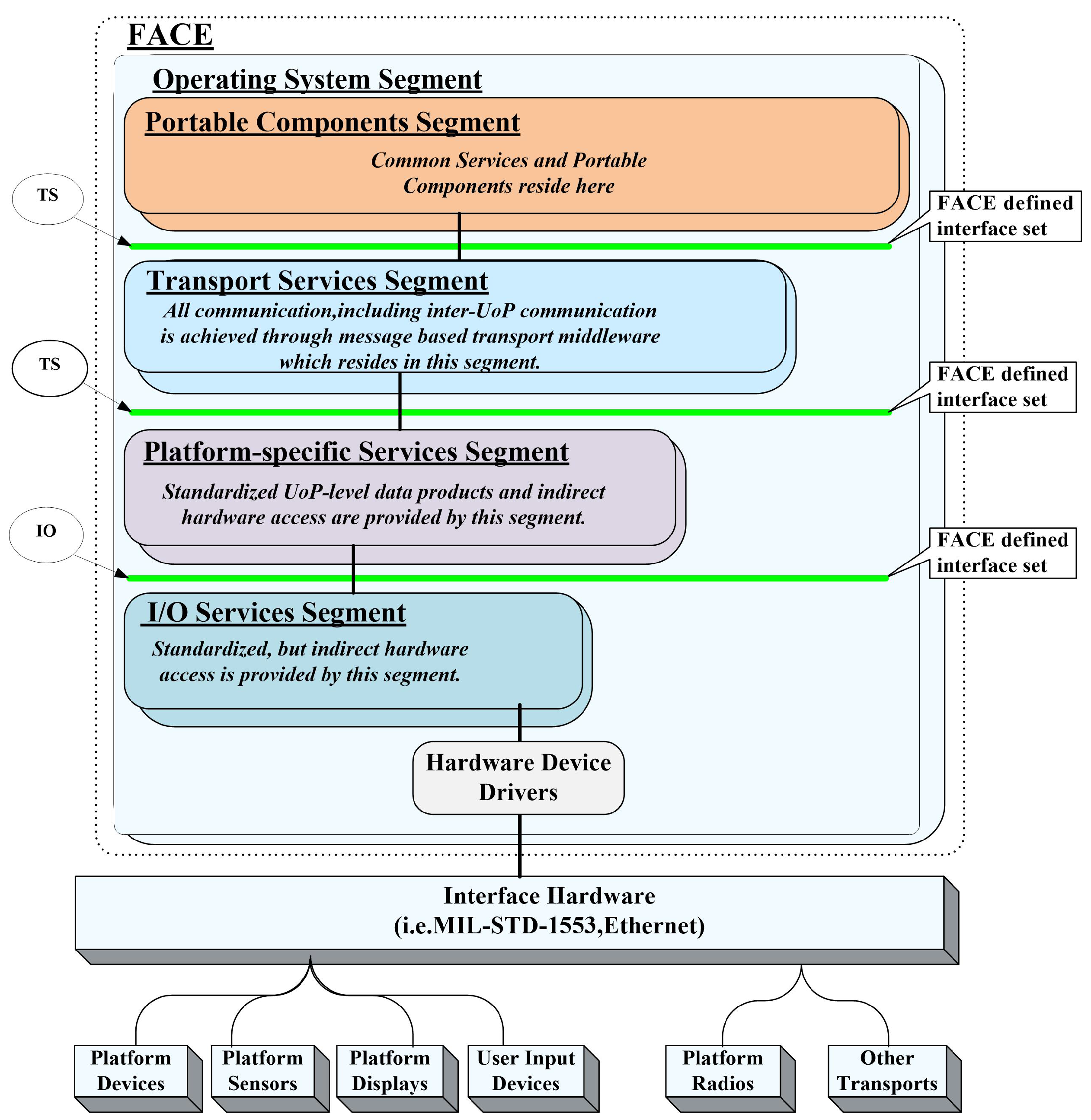
In 2010, FACE (Future Airborne Capability Environment), a new business model and reference architecture proposed for avionics software systems, was jointly promoted by the U.S. military, industry, and academia. In the aviation field, FACE has been widely studied and developed for its promotion of software portability and the formation of software product lines throughout the aviation field. According to the summary and analysis of the functions of several core segments in the FACE software architecture, the functions and capabilities of the avionics systems are mainly reflected by the portable components segment, and all other software segments and interfaces provide services for the portable components segment. In other words, the transport services segment, the platform-specific services segment, the I/O services segment, the operating system segment, and the interface provided form a general software environment combine to support the operation of portable application software and shield the differences of underlying physical platforms [
29,
30,
31]. The FACE architecture is shown in
Figure 1.
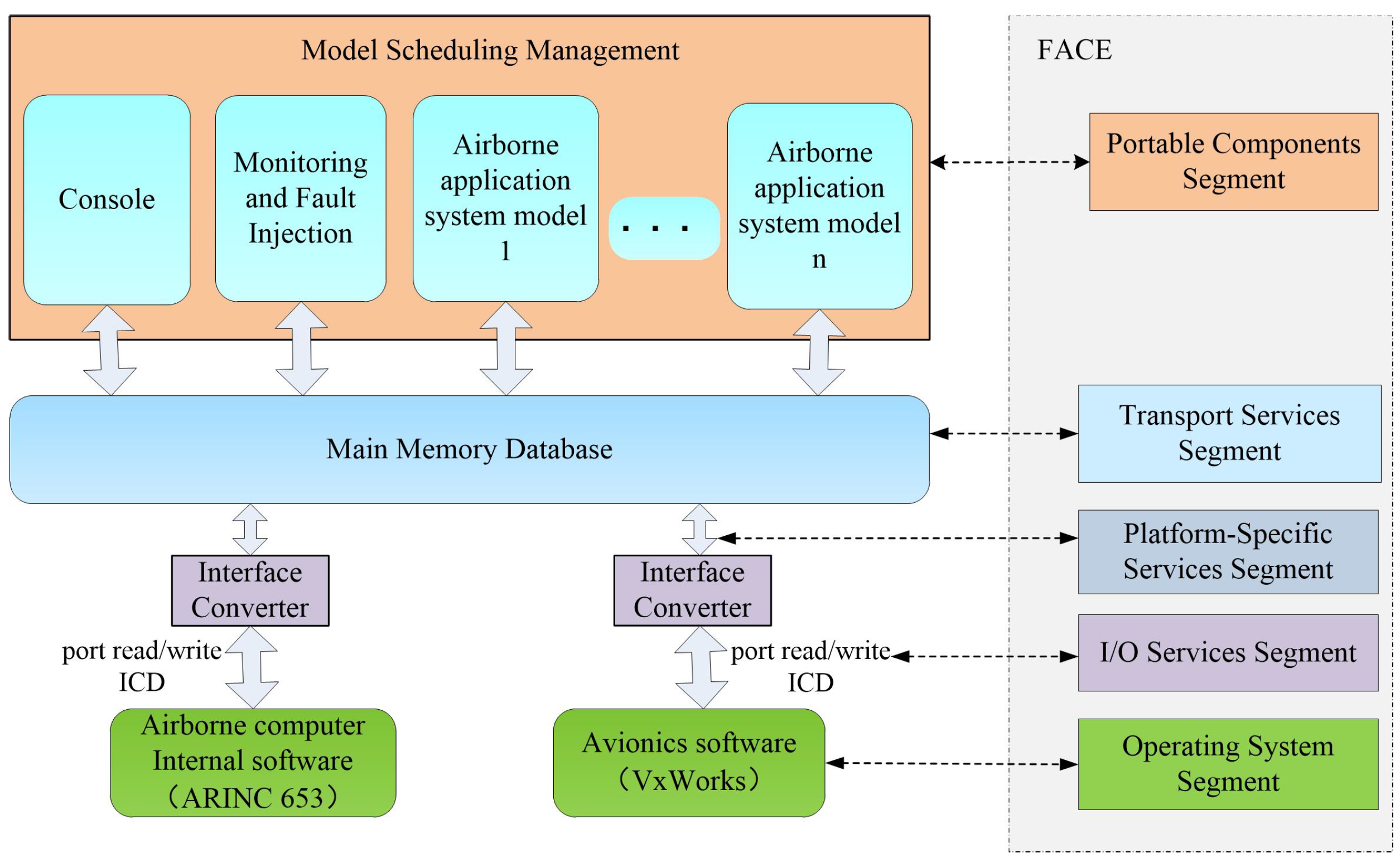
On the basis of the analysis of the simulation and verification platforms for avionics systems, the platform architecture is shown in
Figure 2. The platform adopts the mode of the component plus plug-in, provides a standard operation interface for the component models, supports user-defined components, and has high scalability. The platform provides a scheduling and communication mechanism for the component model and supports the scheduling operation of different components and data communication. Scheduling management supports time-driven and event-driven, which can schedule both periodic and non-periodic tasks in the model, respectively. The underlying communication uses memory database technology to ensure the real-time consistency of data interaction. Configuration management tools can intuitively, easily, and quickly add or modify the table, variable, and mapping in the memory database, thus avoiding the trouble of manually changing configuration files and improving the stability of the system.
In avionics simulation systems, there are all kinds of real or virtual devices. Each device has its own data input/output requirements, read/write mode, and data format. For a specific device, it usually reads data in the specified format (such as ICD) from the specified port or sends data in the specified format from the specified port. The memory database needs to provide these devices with data in accordance with the format and send or receive data at the specified port. The function of the interface converter is to complete the above functional requirements [
32] and uses topic-based publish/subscribe communication mode to send and receive ICD.
ICD is the interface control document, which is used to describe the data structure and underlying data representation of the system and interface, so as to integrate the described elements with other parts of the system conveniently [
33]. Its descriptor is a simple XML file, which contains a serialized model with the defined data structure.
3.2. Component Model
The component model is a physical implementation unit with interfaces, which can be replaced in the system and represents a module of that system. In order to ensure the component model can be loaded and driven, it needs to comply with the corresponding interface specifications [
34,
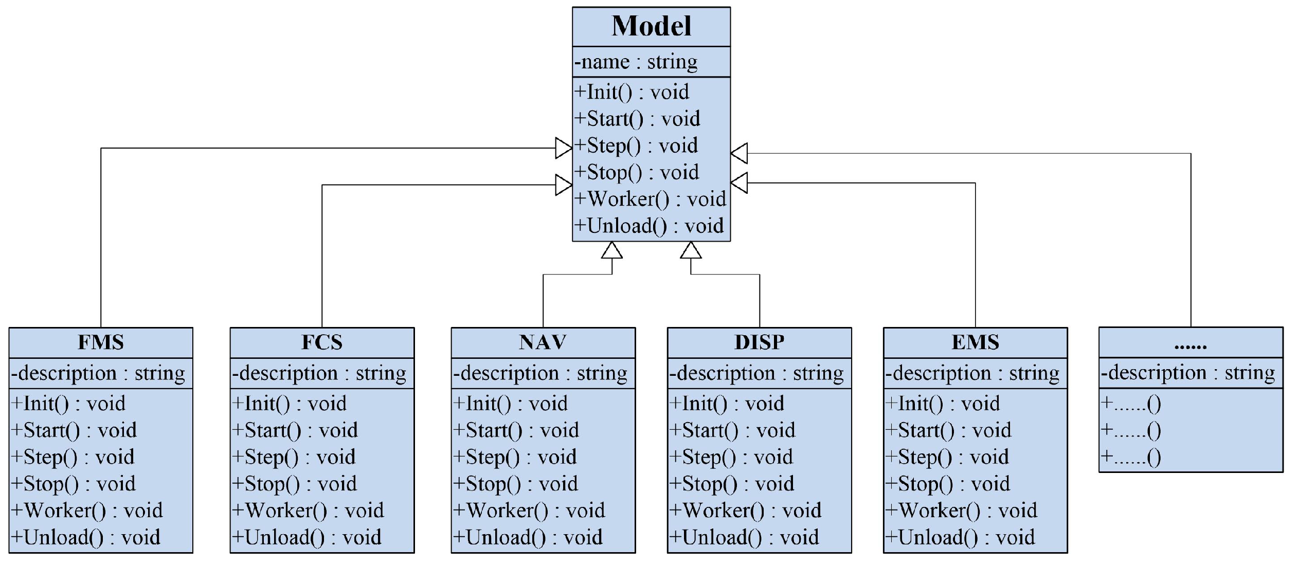
35]. The component model defines the standard interface specification, i.e., the Model class. In the Model class, the interface standards that all component models must comply with are defined. All component models must inherit the Model class and optionally rewrite the external interfaces specified in the Model class.
The Model class is actually the interface specification of the model, in which six external interfaces are defined for users to selectively implement, that is Init(), Start(), Step(), Stop(), Worker(), and Unload(). In synchronous mode, the interfaces that model objects generally call are Init(), Start(), Step(), and Unload(). While in asynchronous mode, the interfaces that model objects generally call are Init(), Start(), Worker(), and Unload().
For example, when developing components such as FMS, DISP, and NAV, only the component class inherits the Model class and selectively implements the related interfaces, as shown in
Figure 3.
3.3. Scheduling Management
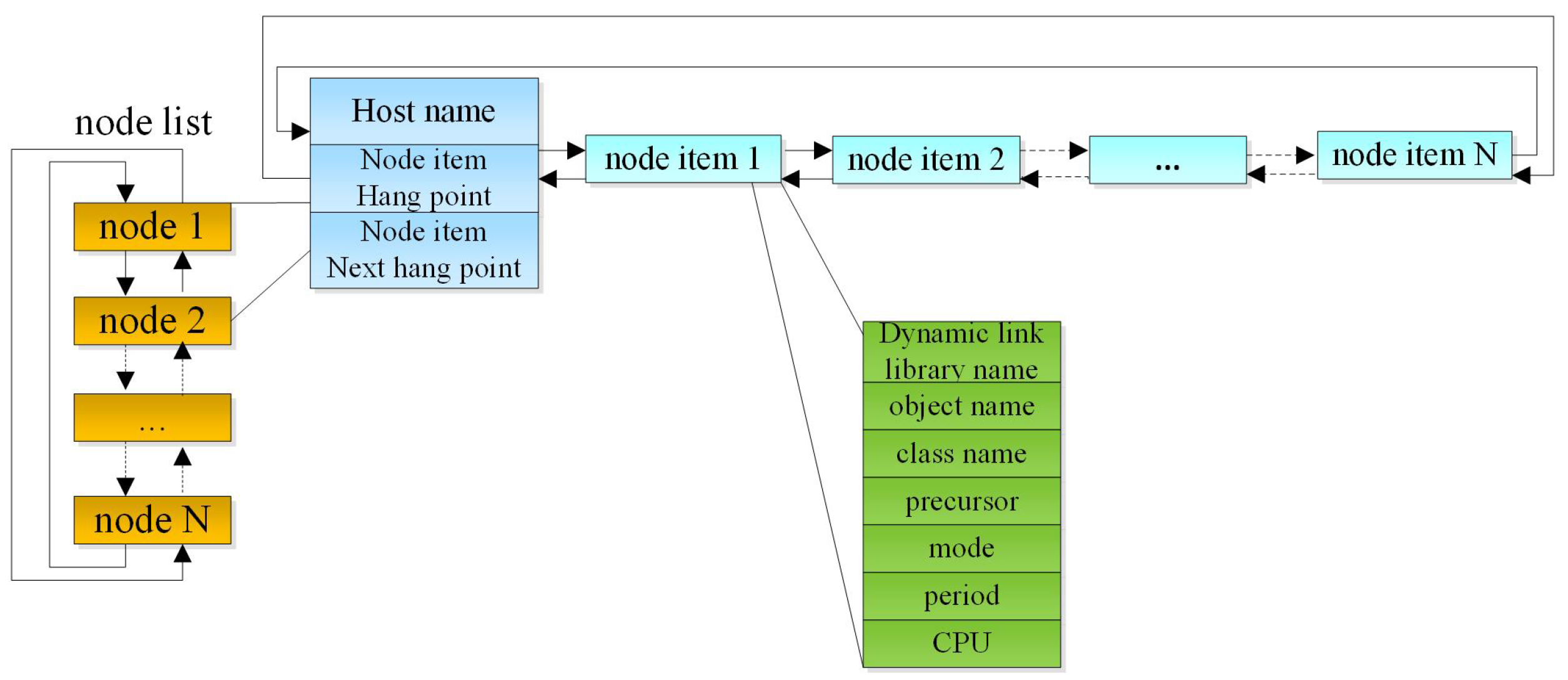
When the custom component is finished, it can be recognized and driven by the scheduling management as a plug-in. To be able to manage loaded plug-ins, a special data structure is needed to manage registered plug-ins. The operation platform will maintain a host list. On each host node, the basic properties of each model object to be loaded will be stored according to the definition in the configuration file, and the scheduling management framework is shown in
Figure 4.
After each plug-in is configured, the scheduling management framework will call the factory method of the model class in the plug-in to generate the corresponding object instance according to the information recorded in each node item within the node list above. Each object instance will be divided into different period groups in accordance with the configured scheduling type, scheduling period, precursor, and other information. The scheduling management framework will manage the model object instances after each instance in a period group. Model objects in each period group have the same scheduling type, the same scheduling period, sharing CPU, and so on.
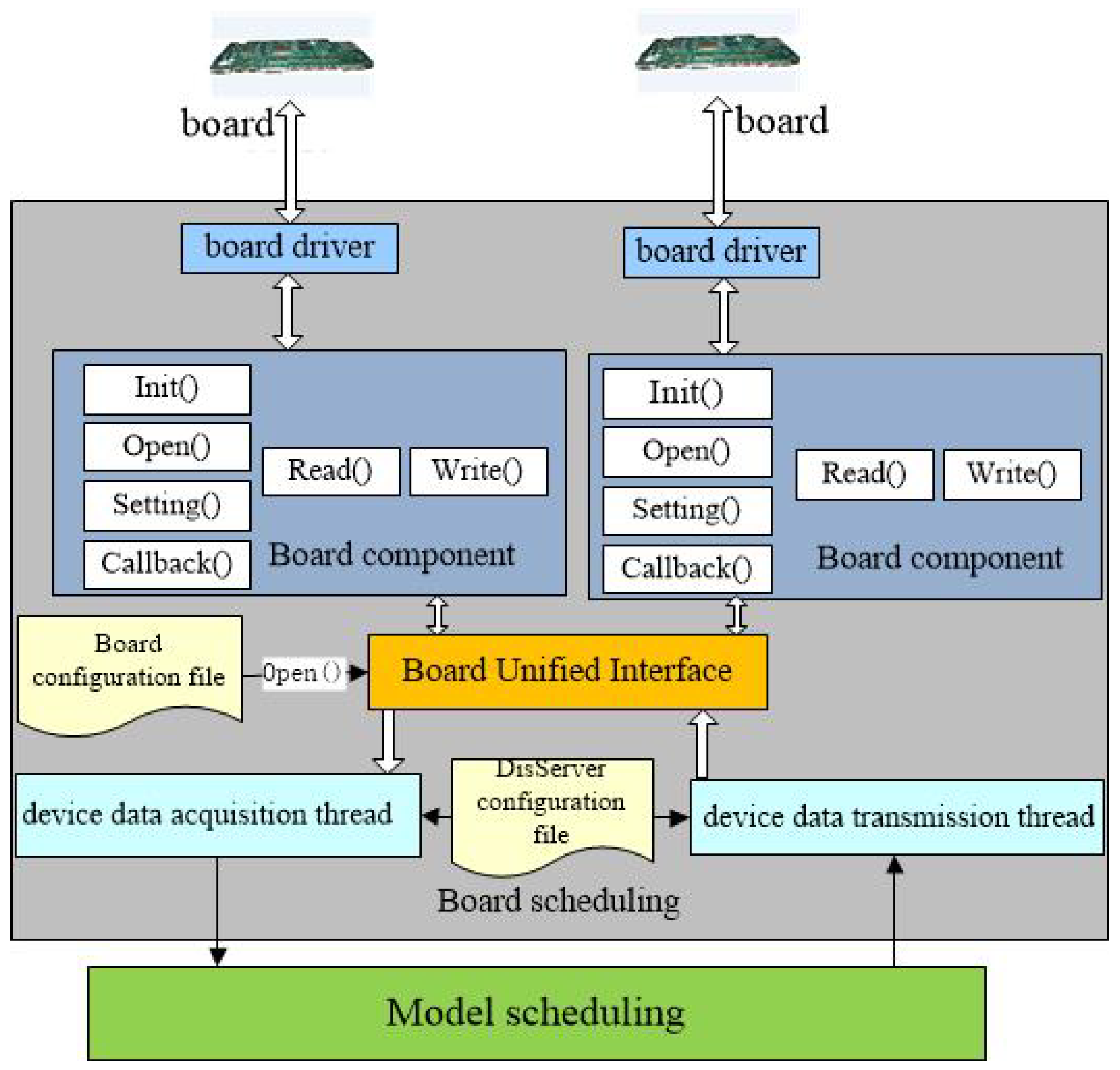
3.3.1. Board Scheduling
The board scheduling opens the corresponding board according to the configuration file and creates the device data acquisition thread and the device data transmission thread. The board component includes board initialization, board opening, board sets, board reading, and board writing. The board scheduling framework is shown in
Figure 5.
The device data acquisition thread obtains the ports in turn based on the list of acquisition ports and checks whether the board to which the port belongs is in the board list. If the board exists, it continues to check whether the board has this port, then reads data from the board and sends it to a component model when the board owns this port.
The device data transmission thread obtains the port in turn based on the collection port list and checks whether the board to which the port belongs is in the board list. If the board exists, it continues to judge whether the board has this port, then reads data from a component model and sends it to the board when the board owns this port.
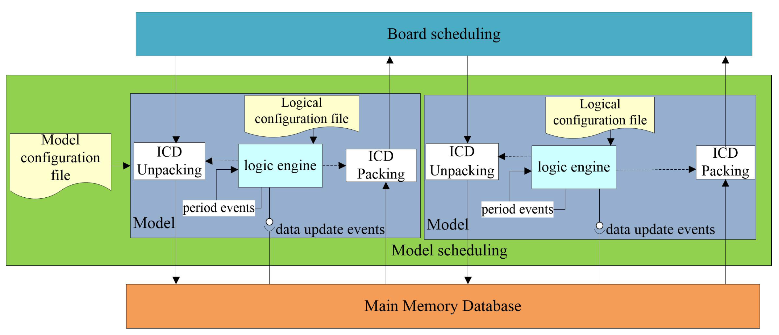
3.3.2. Model Scheduling
In the model scheduling framework, various models are created in accordance with the model configuration file. The model scheduling framework processes the logic of the model on the basis of the logical configuration file and can handle periodic events and data update events. Packing is taking out the data from the main memory database and packing them into ICD, and then sending them to the board schedule. Unpacking is to write the data to the main memory database. The structure is shown in
Figure 6.
3.4. Communication Management
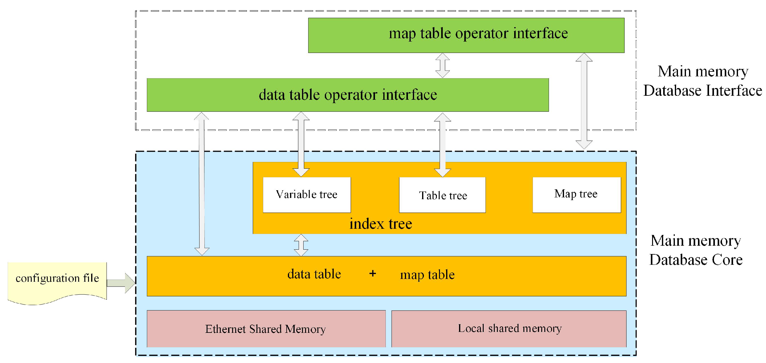
Communication management is implemented by using memory database technology, which manages the data uniformly and resides in the system memory, shields the I/O bottleneck of traditional databases, enhances the real-time data interaction, and ensures the consistency and integrity of the interactive data. The main memory database used in this paper is the storage space based on shared memory. Therefore, all relevant processes can access the data in the database. The main memory database architecture is shown in
Figure 7.
The main memory database provides rich interfaces to support access to all data in the database and provides structure and functions for the conversion of variables and mappings. At the same time, the rich data in the database is generated by reading and processing the configuration file, the specific configuration operation will be introduced in detail in the next section. Therefore, the main memory database not only provides the interaction of data but also provides the interaction between heterogeneous data. The access between heterogeneous data can be as simple as the access variable without any obstacles.
The main memory database includes the data objects needed for the design of the simulation model and data processing in each subsystem. The design meets the requirements of flight integration and verification for shared data. Local shared memory and Ethernet shared memory are used to store and operate shared data in a single machine and distributed situations, respectively.
In the shared memory, all the interactive data between the various application systems are saved, and the global data table, global variable table, and global mapping table are stored in the form of tables. According to the information in the table, the table index tree, variable index tree, and mapping index tree are all created in the shared memory. Meanwhile, when the data in the application cache is synchronized with data in the shared memory, mutual exclusion access to the shared memory is guaranteed by setting the spinlock.
The main memory database function is divided into several modules, which realize the decoupling of the main memory database and improve system portability. Each module cooperates with all others to realize the functional operation of the main memory database.
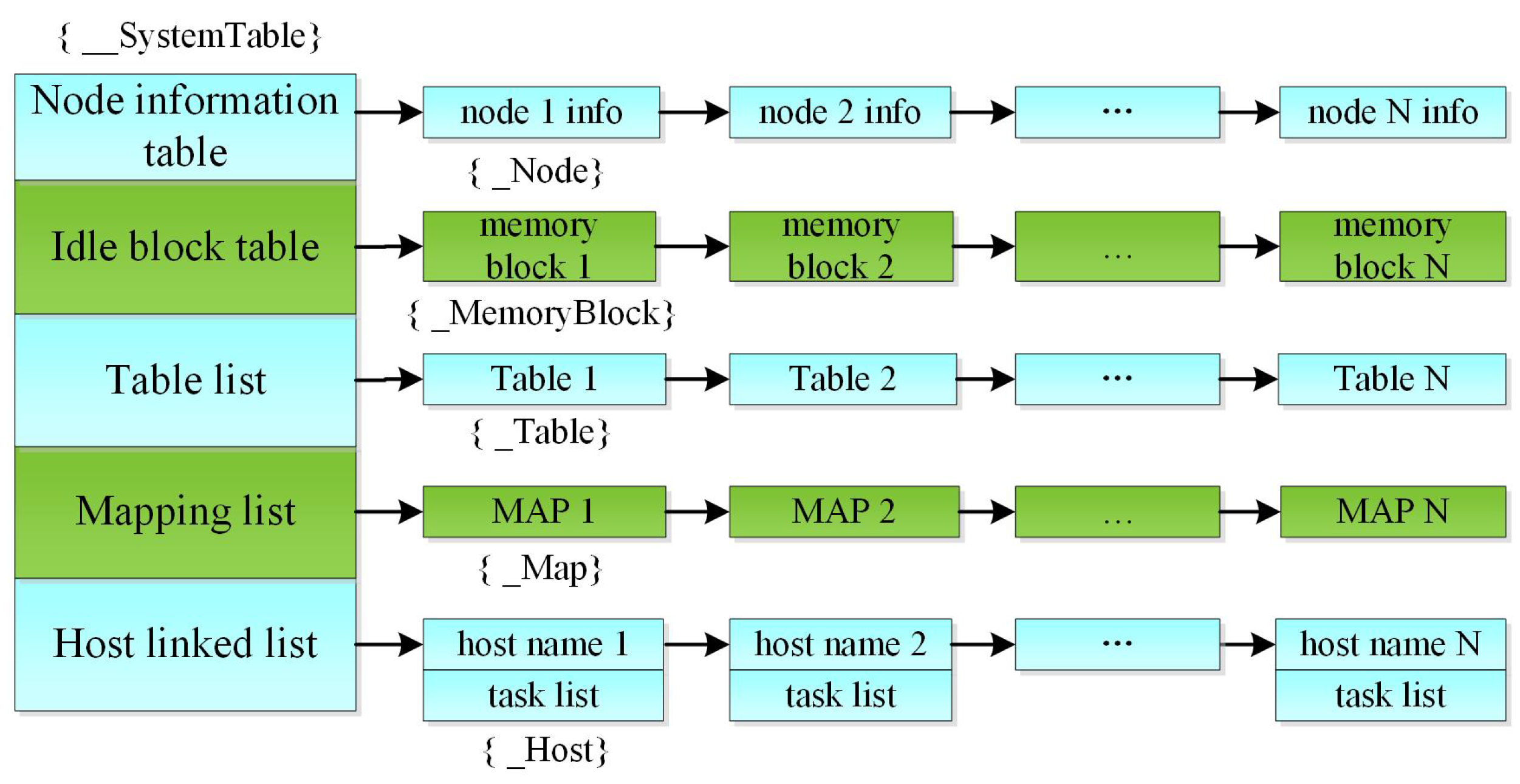
When the platform starts, the system manager will be created, which will record the shared memory address and system management information, and store the required table, index tree, and memory database information. The design of the kernel data structure is shown in
Figure 8, there are five tables in the system table:
1. Node information table, which records lock information for each node in distributed communication mode.
2. Idle blocks table, which stores unused idle blocks.
3. Variable list, which stores the table content parsed by the configuration file.
4. Mapping list, which stores the mapping relationship parsed through the configuration file.
5. Host linked list, which stores the module information parsed by the configuration file.
In order to quickly query the variable table, variable, and mapping position in the system table, the B tree is established to index, the B tree memory contains three trees:
1. A variable table tree, which is used to index the variable table.
2. A variable tree, which is used to index variables.
3. A mapping tree, which is used to index mapping.
In addition, the B tree memory contains an idle block list for use when the B tree memory creates the B tree.
3.5. Configuration Management
Configuration management can configure table, variable, mapping, and host information for the memory database. The configuration management tool can intuitively, easily, and quickly add or change the table, variable, and mapping in the memory database, i.e., the operation information, and generates the corresponding XML configuration files. It avoids the trouble of manually changing configuration files, reduces the errors caused by manual changes, and improves the stability of the system.
1. Table configuration
The Table table stores data in memory, each table has multiple fields, each field has its type, and a single field can be accessed when accessing. We use a four-level index structure to avoid the problem that the same table name cannot be identified between systems. Each table added is equivalent to adding a section of code in the configuration file.
2. Variable configuration
In the configuration tool, the variable configuration is added after the table is established. After the variable information is added, click save, and the configuration tool will write the added information into an XML file named Table. In the XML file, the first pertains to the information of the table, such as the name of the table, Then it is item information, including item name, mode, data type, data length, array number, FIFO default of 1, and default value.
<System name=” “>
<Table name=” “>
<Item name=” “ mode=” “ type=” “ array=” “ fifo= ” “ default=” “ size=” “/>
</Table>
</System>
3. Mapping configuration
The Map table is not used to store data, but to access table data. There is a certain mapping relationship between the items in the table and the fields in the mapping. In this way, the item values in the table can be obtained through the mapping relationship. The mapping configuration is designed for ICD data. When there are variables in the variable table, the existing variables can be added to the mapping, then set the field information, and finally click save. The corresponding relationship between the ICD data field and the variables in the memory database is recorded in an XML file named Map. In the XML file, the initial information is Map, including the name, type, and description of Map, and then the field information, which is the field name, data type, starting byte, ending byte, starting bit, ending bit, and array number, and the variable is named after the name of the associated table.
<Map name=” ”>
<Field name=” “ type=” “ frombyte=” “ tobyte=” “ frombit=” “ tobit=” “ occurence=” “ variable=” “ />
</Map>
4. Host configuration
The host configuration is designed to configure the scheduling framework of the platform, the main idea is to referred to in
Section 3.3. When configuring the host, the host information is added first, followed by the component information, after the addition is finished, it will be saved in an XML file named Host.
4. Experiment and Analysis
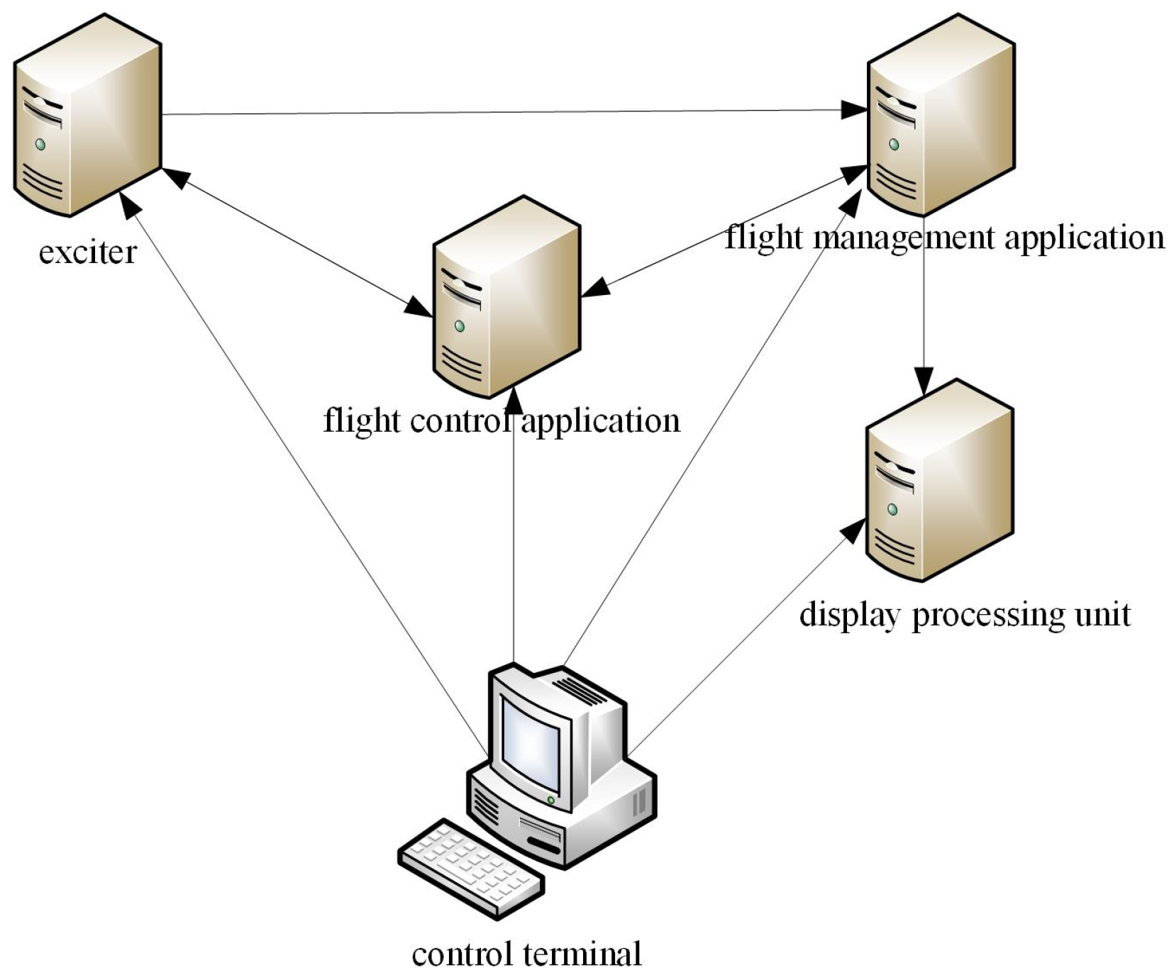
In this section, the function and performance of the proposed simulation and verification platform are evaluated from three aspects: scheduling management, communication management, and configuration management. According to the test results, the feasibility of the simulation and verification platform is analyzed, and by the analysis of the equipment composition, there is the main control terminal, two avionics components (flight management system and flight control system, with each component containing a virtual AFDX board), a display server, and an exciter server. These five devices work together to drive the simulation and verification environment. The network is via Ethernet, and each computer has a memory database so that the interaction between terminals is in the same data pool. Through the establishment of a simulation and verification platform, the model selection, parameter configuration, visual simulation, and detailed evaluation of experimental results have been completely realized.
In the process of simulation and verification, all operations are completed in the main control terminal, the exciter, display processing units, and components are executed by the preset process, and no operator is required to intervene on each machine. Their interaction process is shown in
Figure 9. After the main control terminal successfully starts the software of the exciter, flight control components, flight management components, and display processing unit on each machine, the flight control components continuously receive the flight data from the exciter and flight management components. After parsing, the flight instruction set is generated and sent to the exciter to control the action and attitude of the aircraft. The exciter can set flight parameters and package ICD to send to the flight management components. The flight management components receive the data from the exciter and package them to the display processing unit for dynamic display.
4.1. Function Test
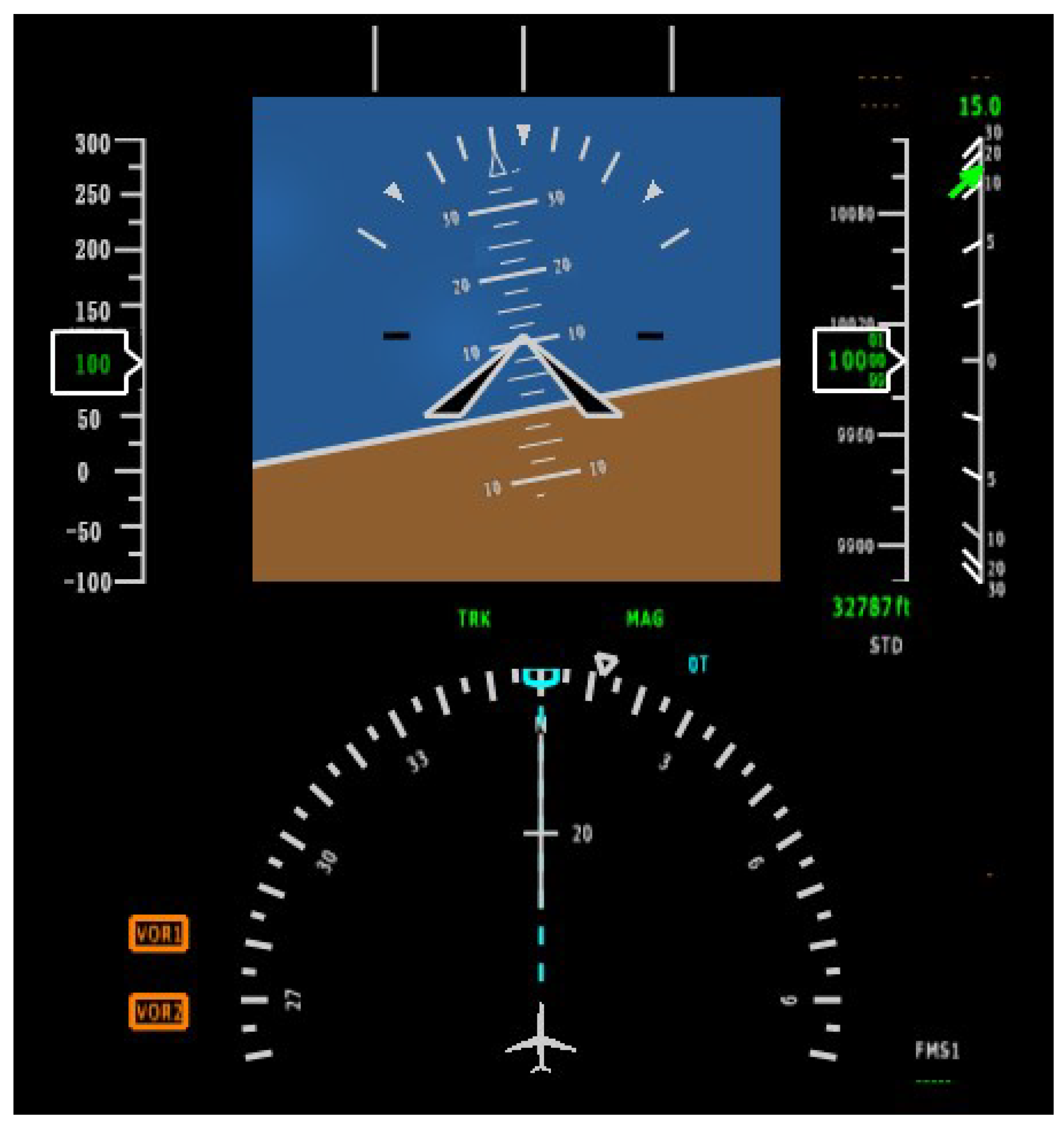
The main control terminal first starts all devices and then sends the flight plan to the flight management component. After receiving the flight plan, the flight management component sends the data to the exciter. The main control set takes off, and the flight control component receives the take-off command, sets the flight instruction set, and sends it to the exciter. After the aircraft takes off, the exciter sets the flying height at 10,000 m, and the display server dynamically displays flight control and verification results, the current flying height is shown in
Figure 10 below.
The test results show that the simulated display environment has the same type of interface elements and graphic elements as the real display environment, and each module can correctly complete its functions according to the expected behavior of the design.
4.2. Performance Test
Finally, the performance of the platform is tested, whereby we use the average response time, load balancing, and communication delay to evaluate the performance of the system. The verification process is controlled through the control terminal, and manual operation is only carried out at the control terminal. Parameters are input to the exciter to generate the specified data, and data information is displayed on the display server as required. On the basis of this, we evaluate the performance in detail through the processing speed of tasks and the communication between components.
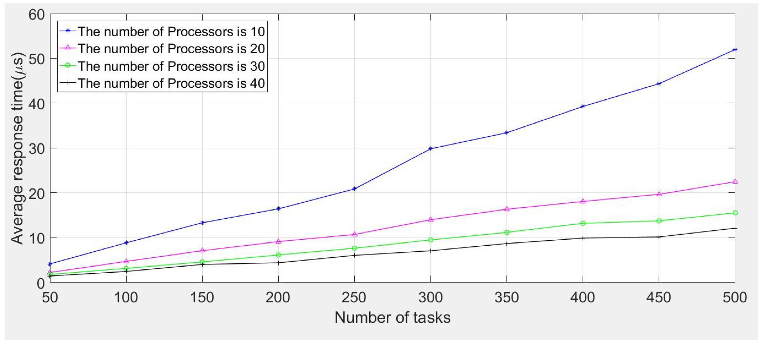
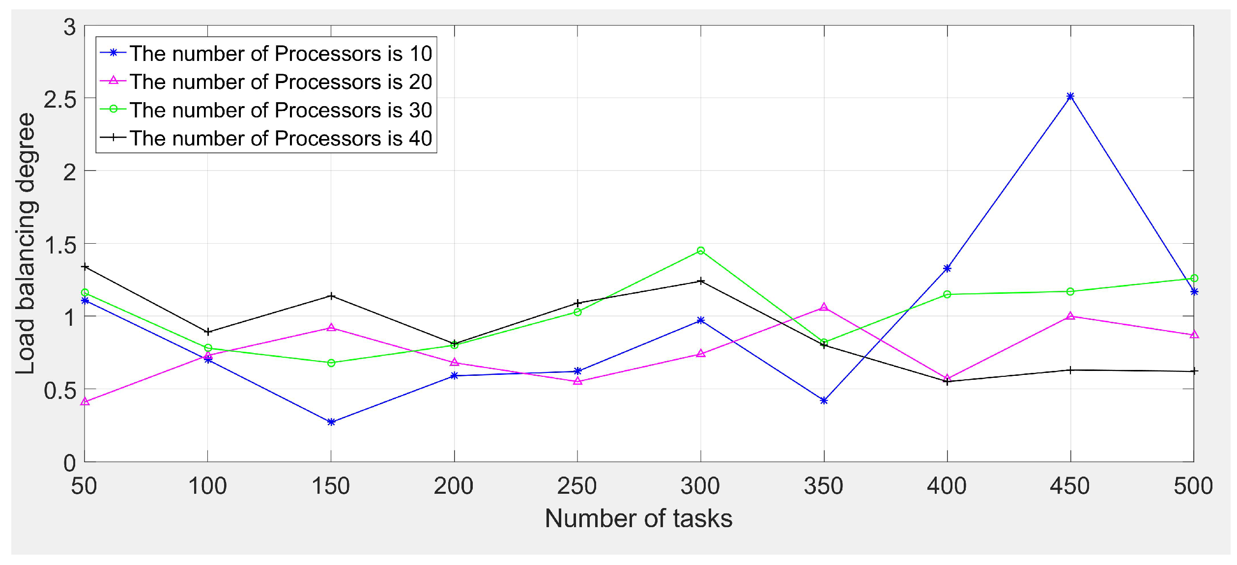
1. Average response time and load balancing tests
To offset the influence of data randomness on the test results, the response time is the average response time of the optimal solution obtained from 20 tests. In the flight management component, the calculation workload of the test task is between 1 MI and 100 MI, and the processing speed of the heterogeneous processor is between 10 MIPS and 100 MIPS. The number of heterogeneous processors is 10, 20, 30, and 40, respectively. The task size is generated from the uniform distribution. When the number of tasks is 50, 100, 150, 200, 250, 300, 350, 400, 450, and 500, respectively, the first come first service strategy is utilized to obtain the average response time (as shown in
Figure 11) and the load of the system (as shown in
Figure 12), and the analysis of test results is shown in
Table 1. Here, we use the standard deviation (stdev) of load balancing as the degree of load balancing in avionics systems. The larger the standard deviation is, the more unbalanced the load distributions of avionics systems become. The test results show that the system has a good response speed. However, the load balancing is slightly poor. This is because we need to process tasks quickly rather than pursuing load balancing in avionics systems.
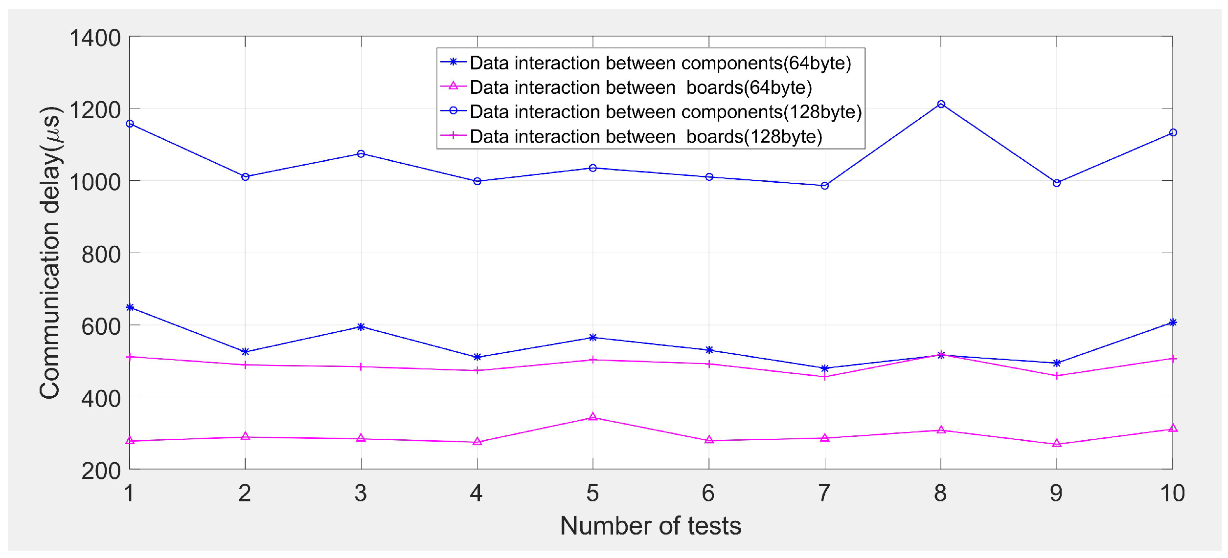
2. Communication delay testing
We evaluate the performance of communication by sending and receiving ICD messages between the two components. The size of the packet is 32 bytes, 64 bytes, 128 bytes, and 256 bytes, respectively, and the number of tests is 10, including data interaction between flight management components and flight control components, and data interaction between the virtual AFDX board of flight management components and the virtual AFDX board of flight control components. The communication delay between components and boards is shown in the following figure. The test results are given in
Figure 13 and
Table 2. Here, we use the standard deviation of communication delay as the stability of communication in avionics systems. It can be seen that the communication delay of the platform is less than 2 milliseconds. The larger the data packet, the longer the delay. Overall, it still has good communication characteristics.


