Article

A Point Crack Source Location Method without Velocity Information in Anisotropic Plates

1
Department of Mathematics, Yonsei University, Wonju 26493, Korea
2
Department of Mechanical Engineering, Ajou University, Suwon 16499, Korea
3
Institute for Advanced Engineering, Yongin 17180, Korea
4
Division of Software, Yonsei University, Wonju 26493, Korea
*
Author to whom correspondence should be addressed.
Appl. Sci. 2022, 12(21), 11081; https://doi.org/10.3390/app122111081
Submission received: 30 September 2022 / Revised: 28 October 2022 / Accepted: 29 October 2022 / Published: 1 November 2022
(This article belongs to the Section Applied Industrial Technologies)

Abstract

:
Locating cracks in a solid object using acoustic emission (AE) is useful both for detecting defects during safety monitoring and for basic laboratory studies of fractures. We developed an acoustic source location (ASL) method without the use of velocity information with AE in anisotropics plates, such as carbon fiber-reinforced polymers. Assuming that the propagation velocity of an unknown elastic wave is constant in anisotropic materials, the objective function to be minimized is defined based on the elliptic wavefront shape-based technique. The objective function is minimized using an iterative method, such as the gradient descent method. As a result of the numerical experiments and PLB testing on a carbon fiber-reinforced polymer plate, the method is accurate within 5% and is stable against noise.

1. Introduction

Acoustic emission (AE) is a phenomenon in which an elastic wave is generated when microcracks start forming before a material is destroyed, during the process of small deformations, or when a material is destroyed. The method for detecting and evaluating this elastic wave with sensors is called AE testing [1]. The purpose of AE testing is to diagnose the tendency of the occurrence of AE, to find the location of the defect in the material, and to know what is happening at the source. AE testing can be applied to various materials, such as concrete [2,3], still [4,5], and fiber-reinforced plastics [6], depending on several application areas [7].
Finding the crack location or acoustic source location (ASL) of a subject using AE is valuable both for locating defects during safety monitoring and for fundamental laboratory studies of fractures. To locate a crack, multiple AE sensors are used to measure the AE signals from a single acoustic source. There are two ways to find a crack’s location: using a measured signal waveform and using a signal parameter such as the signal arrival time, or the so-called time of arrival (TOA). Time reverse modeling (TRM) is a location method [8,9] which uses the entire measured AE signal waveform. The TRM method uses the measured AE signal as an input source to solve the elastic equation and provide the location of the crack and the characteristics of the crack. This method has disadvantages in that it is necessary to know the properties of the object and to solve the elastic wave equation.
To find a crack’s location using the TOA, many researchers have developed ASL methods for isotropic and anisotropic objects. The ASL methods widely used in isotropic media include the triangular position representation method [10] and the simplex method [11], and several other methods can be found in [12,13]. In anisotropic materials, since the elastic wave speed is different depending on the propagation direction [14], it is necessary to develop an ASL method in consideration of this [6,15].
For the anisotropic materials, the ASL techniques are studied based on the optimization technique [16,17,18]. These methods estimate the locations of cracks using the time measured by the sensor and the propagation speed for each angle of the anisotropic material. There have been many studies to develop an ASL method for the case where the propagation speed of an anisotropic medium is unknown [19,20,21,22]. In order to avoid using the propagation speed in anisotropic media, the prior research’s approaches require special sensor placements, namely the L-shaped sensor clusters in [19,20,23], Z-shaped sensor clusters in [21], and square-shaped sensor clusters in [22].
In this paper, we propose an ASL method using only the TOA in anisotropic plates. This method allows for arbitrary placement of the sensor and includes the TOA errors. The proposed ASL method has an iterative scheme to minimize the nonlinear least squares. The objective function of the least squares is generated by assuming that the propagation velocity of an elastic wave in an anisotropic material is constant and based on the ellipse equation [16,17], which is modified so that the unknown velocity term is erased. In addition, we add the TOA error correction constant to the objective function and apply a well-known Tikhonov regularization method [24] for stable solving of the optimization problem. We call the proposed ASL method the speed deviation minimization method (SDMM), because it is designed to minimize the difference in speed measured by each sensor. The result of applying the SDMM is the estimated crack position of the material, the crack start time, and the wave propagation velocity, of which the estimated crack position is used as the final result. Many experiments were conducted to evaluate the accuracy and robustness of the crack location by the SDMM. As a result of the experiment, it has been confirmed that it has an accuracy within 5% and works stably against noise.
This paper is organized as follows. In Section 2, the SDMM is introduced. In order to check the accuracy and robustness of the method, we performed three types of experiments to generate the AE signal from the (1) analytical formula, (2) elastic wave equation, and (3) PLB test on a single CFRP plate. The experimental settings are explained in Section 3, and the experiment results are provided in Section 4. At the end, Section 6 provides our conclusions, and Section 5 gives a discussion.

2. Methodology

2.1. Elliptic Wavefront

We consider a wave propagation in an elliptical shape on the CFRP’s surface. For an ellipse reaching the ith sensor, the center is the location of the crack ( x , y ) , and the lengths of the two axes are ( t i t ) v x and ( t i t ) v y in the directions x and y, respectively, where t i is the wave arrival time at the ith sensor and v x and v y are the wave speed in the x and y directions, respectively (see Figure 1). Thus, we have the following ellipse equation:
( x i x ) 2 ( t i t ) 2 v x 2 + ( y i y ) 2 ( t i t ) 2 v y 2 = 1
where t is the crack occurrence time.
We multiply v x 2 on both sides of Equation (1) and let α = v x / v y , and then
( x i x ) 2 ( t i t ) 2 + ( y i y ) 2 α 2 ( t i t ) 2 = v x 2
for any i = 1 , 2 , , n , where n is the number of sensors. Note here that the problem involves finding ( x , y ) from t i for i = 1 , 2 , , n , where t, v x , and α are unknown values.
Since v x is a constant independent of i = 1 , 2 , , n in Equation (2), we have
v x 2 = ( x i x ) 2 + ( y i y ) 2 α 2 ( t i t ) 2 = ( x j x ) 2 + ( y j y ) 2 α 2 ( t j t ) 2
for any i , j = 1 , 2 , , n . Multiplication of the fraction by the denominator on the left and right sides gives
( t j t ) 2 ( x i x ) 2 + ( y i y ) 2 α 2 ( t i t ) 2 ( x j x ) 2 + ( y j y ) 2 α 2 = 0
for distinct i , j = 1 , 2 , , n . Here, we can obtain as many equations as the number of combinations of i and j.

2.2. Signal Arrival Time Error Correction

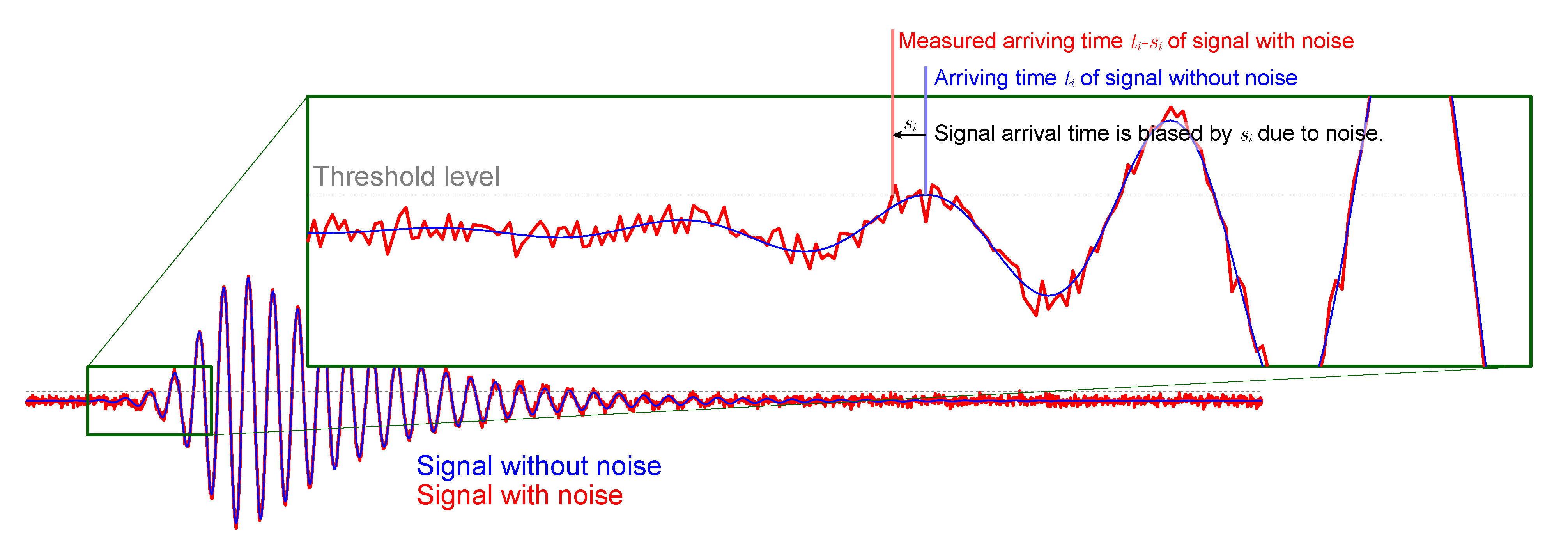
For measuring the arrival time t i from the AE signal, there are several methods [25,26,27], but the threshold method is commonly used. However, because the AE signal contains a lot of noise, errors in the time of arrival measured by the threshold method are unavoidable (see Figure 2). In order to reflect the error of the arrival time in the equation, we introduce a time offset value s i at the ith sensor. As shown in Figure 2, the signal arrival time was biased by s i due to noise. Thus, the signal arrival time in the presence of noise can be written as t i s i , where t i is the arrival time of the signal in the absence of noise and s i is the bias of the signal arrival time due to noise.
Thus, in the following equation, from Equation (3), we do not use the measured time t i but the time t i s i , for which the error was corrected:
( ( t j s j ) t ) 2 ( x i x ) 2 + ( y i y ) 2 α 2 ( ( t i s i ) t ) 2 ( x j x ) 2 + ( y j y ) 2 α 2 = 0

2.3. Objective Function and Minimization

A simple optimization problem for finding ( x , y ) from Equation (4) is to minimize g ( x , y , t , α , ) , which is defined as
g ( x , y , t , α , ) = i j t ( t j s j ) 2 ( x x i ) 2 + ( y y i ) 2 α 2 t ( t i s i ) 2 ( x x j ) 2 + ( y y j ) 2 α 2 2
However, we have more variables ( n + 3 variables: x, y, t, α , s 1 , ⋯, s n ) than the amount of measurement data (n data: t 1 , ⋯, t n ). This lack of information can be overcome by introducing the regularization term | s | 2 into the optimization process as follows:
( x , y , t , α , ) = argmin ( x , y , t , α , )   g ( x , y , t , α , s ) + λ | s | 2
where λ is a given constant.
There are various techniques for solving the unconstrained minimizing problem in Equation (5), such as the gradient descent method, conjugate gradient method, and Newton’s method [28]. In this paper, we use the gradient descent method, which requires the gradient of f ( x , y , t , α , ) = g ( x , y , t , α , ) + λ | s | 2 . Since the derivative result of the objective function f is complicated, we provide the gradient of f ( x , y , t , α , ) = g ( x , y , t , α , ) + λ | s | 2 here for the convenience of the reader: f = f x , f y , f t , f α , f s 1 , f s 2 , , f s n T where
f x = 4 i j t ( t j s j ) 2 ( x x i ) 2 + ( y y i ) 2 α 2 t ( t i s i ) 2 ( x x j ) 2 + ( y y j ) 2 α 2 × t ( t j s j ) 2 ( x x i ) t ( t i s i ) 2 ( x x j ) f y = 4 i j t ( t j s j ) 2 ( x x i ) 2 + ( y y i ) 2 α 2 t ( t i s i ) 2 ( x x j ) 2 + ( y y j ) 2 α 2 × t ( t j s j ) 2 ( y y i ) α 2 t ( t i s i ) 2 ( y y j ) α 2 f t = 4 i j t ( t j s j ) 2 ( x x i ) 2 + ( y y i ) 2 α 2 t ( t i s i ) 2 ( x x j ) 2 + ( y y j ) 2 α 2 × t ( t j s j ) ( x x i ) 2 + ( y y i ) 2 α 2 t ( t i s i ) ( x x j ) 2 + ( y y j ) 2 α 2 f α = 4 i j t ( t j s j ) 2 ( x x i ) 2 + ( y y i ) 2 α 2 t ( t i s i ) 2 ( x x j ) 2 + ( y y j ) 2 α 2 × t ( t j s j ) 2 ( y y i ) 2 α t ( t i s i ) 2 ( y y j ) 2 α f s k = 4 k i ( ( x x i ) 2 + ( y y i ) 2 α 2 ) ( t s k ) × ( ( x x i ) 2 + ( y y i ) 2 α 2 ) ( t s k ) 2 ( ( x x k ) 2 + ( y y k ) 2 α 2 ) ( t s i ) 2 + 2 λ s k

3. Experiments

3.1. Robustness

This section is devoted to explaining the numerical experiment settings for testing the noise robustness of the location estimation method. For the numerical experiments, we generated the signal arrival time t i using the following equation derived from Equation (1) for i = 1 , 2 , , N
: t i = t + ( x i x ) 2 v y 2 + ( y i y ) 2 v x 2 v x 2 v y 2
where N is the number of sensors, assuming that the crack occurrence point ( x , y ) and the position ( x i , y i ) of the sensors are given on the x y plane and the propagation velocities v x are v y of the elastic wave in the x and y directions are given.
Figure 3 shows the numerical experiment settings in the domain [ 4 , 4 ] × [ 2 , 2 ] . The source location in the figure is marked with a red dot at (1,0), and various crack locations at (1,0), (2,0), (3,0), (1,1), (2,1), and (3,1) were tested in the numerical experiments. For ease of viewing, only one sensor (blue dot) is shown in the figure, but numerical experiments were performed with varying numbers of sensors (4, 6, 8, 10, and 12). Here, for a variable number of sensors, we always spaced them equally at the boundary of the domain. For the wave propagation, we used the propagation velocities v x = 3 and v y = 1 (i.e., the elastic wave in the x direction was three times faster than that of y direction).
To check the robustness of the algorithm against noise, we added Gaussian random noise n i to the time data t i . Here, t i is generated by computing Equation (6), and n i is a pseudorandom value drawn from the normal distribution with a mean of 0 and standard deviation σ . To experiment with varying the magnitude of the noise according to the magnitude of the time data, we adopted the alternative definition of the SNR [29,30], denoted as ASNR , which is the ratio of the mean to the standard deviation of the signal arrival time t i i = 1 N , as shown below:
ASNR = μ σ
where μ is the mean of t i i = 1 N . In this paper, we use ASNR = 10, 30, 50, and . Here, for notational simplicity, it is expressed as ASNR = when there is no noise. For each noise level, the average of the relative errors from a total of M = 100 experiments is used. The relative error of the source location is defined as the ratio of the distance error to the diameter of a circle having an area equal to the area of the domain, and the distance error is the distance between the crack location and the estimated location.

3.2. Numerical Experiment Based on a Physical Model

Numerical AE data were used to test the location estimation method. In order to create numerical AE data, the following elastic equation had to be solved:
ρ t t u i = j ( c i j k l l u k ) + f i i n Ω × [ 0 , T ]
where t is the time variable, i , j , k , l { 1 , 2 , 3 } , ρ is the gravitational density, i is the partial derivative on i, f i is the wave source caused by cracking, and c i j k l is the stiffness tensor of the object. The crack becomes a source of vibration f i in the elastic equation, and the measured AE signal can be obtained from the solution u = ( u 1 , u 2 , u 3 ) of the elastic equation at the measurement location. Note that the stiffness tensor C = c i j k l can be obtained from the elastic properties of Young’s modulus E, the Lamé parameter λ , the shear modulus ( G , μ ) , and the Poisson ratio ν [31] for a CFRP plate which has the orthotropic linear elasticity property:
C = C 11 C 12 C 13 0 0 0 C 12 C 22 C 23 0 0 0 C 13 C 23 C 33 0 0 0 0 0 0 C 44 0 0 0 0 0 0 C 55 0 0 0 0 0 0 C 66 .
where
C 11 = E 1 2 E 3 ( E 3 v 23 2 + E 2 ) E 1 2 E 2 v 31 2 + 2 E 1 E 2 E 3 v 12 v 23 v 31 E 1 E 2 E 3 + E 1 E 3 2 v 23 2 + E 2 2 E 3 v 12 2 C 12 = E 1 E 2 E 3 ( E 2 v 12 + E 1 v 23 v 31 ) E 1 2 E 2 v 31 2 + 2 E 1 E 2 E 3 v 12 v 23 v 31 E 1 E 2 E 3 + E 1 E 3 2 v 23 2 + E 2 2 E 3 v 12 2 C 13 = E 1 E 2 E 3 ( E 1 v 31 + E 3 v 12 v 23 ) ( E 1 2 E 2 v 31 2 + 2 E 1 E 2 E 3 v 12 v 23 v 31 E 1 E 2 E 3 + E 1 E 3 2 v 23 2 + E 2 2 E 3 v 12 2 C 22 = E 1 E 2 2 ( E 1 v 31 2 + E 3 ) E 1 2 E 2 v 31 2 + 2 E 1 E 2 E 3 v 12 v 23 v 31 E 1 E 2 E 3 + E 1 E 3 2 v 23 2 + E 2 2 E 3 v 12 2 C 23 = E 1 E 2 E 3 ( E 3 v 23 + E 2 v 12 v 31 ) E 1 2 E 2 v 31 2 + 2 E 1 E 2 E 3 v 12 v 23 v 31 E 1 E 2 E 3 + E 1 E 3 2 v 23 2 + E 2 2 E 3 v 12 2 C 33 = E 2 E 3 2 ( E 2 v 12 2 + E 1 ) E 1 2 E 2 v 31 2 + 2 E 1 E 2 E 3 v 12 v 23 v 31 E 1 E 2 E 3 + E 1 E 3 2 v 23 2 + E 2 2 E 3 v 12 2 )
when we follow Voigt notation [32].
The experimental domain is a rectangular CFRP plate 9 × 9 cm 2 in size. The elastic properties of the CFRP were obtained from [33], which are
E = E 1 E 2 E 3 = 192.44 23.39 23.39 , G = G 12 G 23 G 31 = 9.08 10.75 9.08 , ν = ν 12 ν 23 ν 31 = 0.23 0.37 0.23
when units of the E and G are GPa. The AE source, to create the AE data, is defined as below at a single point, and we had four AE source candidate positions (red dots in Figure 4):
f ( t ) = 1 2 ( 1 cos ( 2 π · p t / 5 ) ) sin ( 2 π · p t ) , 0 < t < 5 / p 0 , o t h e r w i s e
where p = 140 × 10 3 . Note that the excitation signal f ( t ) is a Hanning-windowed, 5-count, 1400-kHz tone burst signal, which was shown to be suitable for many industrial applications of guided waves [34,35]. This source function gives the measured signal a similar shape to the actual AE signal. We used Comsol Multiphysics (Comsol, Inc., Burlington, MA, USA) to solve the elastic equation (Equation (8)). By solving Equation (8), the propagated wave was measured at eight positioned sensors (blue dots in Figure 4), and we obtained eight arrival times at each position accordingly. Note that it was necessary to provide a mesh of an appropriate size that satisfied the stability condition (CFL condition) and dispersion condition [36], since COMSOL Multiphysics is finite element analysis simulation software.
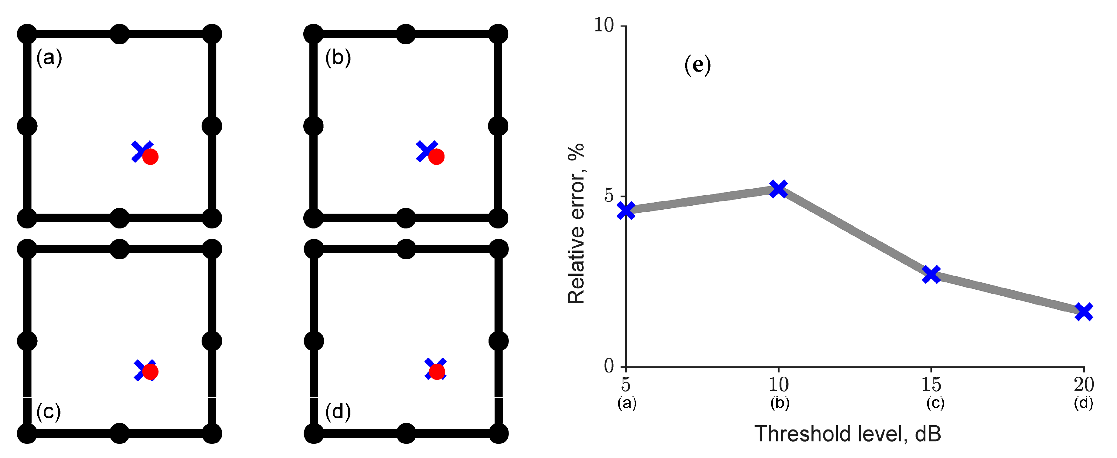
To check the robustness of the algorithm against the signal’s arriving time, or the so-called time of arrival (TOA), we added ASNR = 10 of Gaussian random noise to the AE data (not the measurement time data) and used four threshold levels—5, 10, 15, and 20 dB—to determine the TOA of the noise AE data. For each threshold level, the average of the relative errors from a total of M = 100 experiments was used. Note that the ASNR was defined in Equation (7).

3.3. Cfrp Phantom Experiment

We performed PLB testing on the single layer of CFRP in order to obtain AE data, which were for the location estimation method. For AE data collection, a CFRP plate with an area of 500 × 500 mm 2 and a thickness of 6 mm, which was manufactured by a winding method so that the fibers were oriented in a single direction as shown in Figure 5, was used.
A total of seven AE sensors were installed to measure the PLB signal generated on the surface of the CFRP plate. The sensor used was model R15i-AST, manufactured by PAC (Physical Acoustics Corporation, a member of MISTRAS Group Inc., Princeton Junction, NJ, USA) with a resonant frequency of 150 kHz. To collect the signal measured through the sensor, a PC-based acoustic emission signal collection device was used, and PAC’s Express-8 board and AEwin software were applied. The main measurement variables of the signal collector were set as shown in Table 1, and the AE variables were calculated by collecting the AE signals for each hit unit based on timing variables such as the PDT, HDT, and HLT.
In particular, the HLT value was set relatively high so that the reflected wave was not measured. In addition, the sampling rate was set to 2 MHz according to the measurement frequency range of the sensor used, and a threshold and a frequency band filter (digital filter) were used so that the background signal (noise) was not collected. In an experiment to create one AE datum, the location of the PLB was a single point, and we had four AE source candidate positions (red marks in Figure 5). By solving the elastic equation, the propagated wave was measured at seven positioned sensors (blue marks in Figure 5), and we found seven arrival times at each position accordingly.

4. Results

In this section, we show the experimental results as described in Section 3. Twelve sensors were attached in Section 4.1, eight in Section 4.2, and seven in Section 4.3. However, the method uses seven TOAs in a small order (i.e., seven sensors are used in the order the signals are first received).

4.1. Robustness on Noise

In this section, we present the numerical experimental results to test the noise robustness of the source location method with the concept of ASNR defined in Equation (7). The numerical experiment settings were explained in Section 3.1, and the result figures are shown in Figure 6.
The estimated location with the SDMM applied are depicted in Figure 6a–d. In the figure, the red dot is the source location, the blue plus sign (+) and the blue cross (x) indicate the predicted crack locations when λ = 0 and λ 0 , respectively. As can be seen in the figure, the estimated location when λ 0 , marked by a blue cross (x), found the source location better as the ASNR increased, whereas the estimated location when λ = 0 , denoted with a blue plus sign (+), did not find the source location well regardless of the ASNR value. Therefore, when λ = 0 (i.e., when there was no regularization term), the estimated location hardly moved to the crack location, and when λ 0 (i.e., when there was a regularization term), the estimated location moved to the crack location. For quantitative analysis, the relative error (distance error for the diameter of a circle with the same area as the experimental area) was calculated as follows:
relative = distance error 2 domain area / π
The relative error according to the ASNR value of the noise can be seen in Figure 6e, and it can be seen that the relative error was less than 15% when the noise in the TOA was ASNR 30 .

4.2. Robustness on TOA Thresholds

In this section, we provide the experimental results of the numerical AE data to confirm the SDMM method’s results for the TOA thresholds. Numerical AE data were obtained by solving the elastic equations. Detailed descriptions can be found in Section 3.2.
The estimated positions with the SDMM applied are shown in Figure 7a–d. In the figure, the red dot is the source location, and the blue cross (x) indicates the predicted crack location. As can be seen in the figure, the estimated location, marked by a blue cross (x), was always near the crack location, denoted by a red dot. For quantitative analysis, the relative error (distance error for the diameter of a circle with the same area as the experimental area) was calculated as in Equation (9). The relative error due to the TOA value can be seen in Figure 7e, and it can be seen that the relative error was always less than 10% regardless of the TOA value.

4.3. Plb Test on the CFRP Plate

This section shows the results of the PLB experiments with the SDMM applied at various PLB positions. The experimental settings are described in Section 3.3, and the resulting diagram can be found in Figure 8.
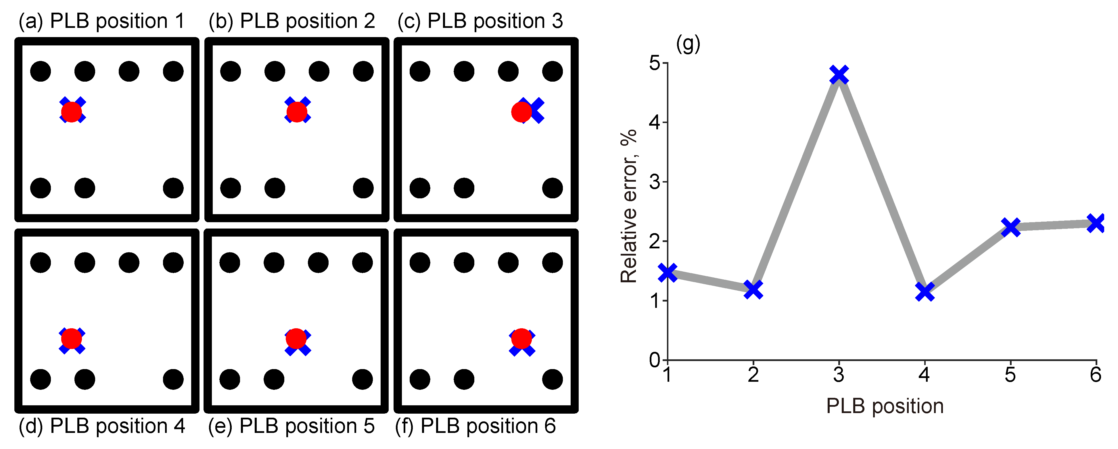
The estimated positions to which the SDMM were applied are displayed in Figure 8a–f. The black dots in the figure are the sensor positions, the red dots are the PLB positions, and the blue plus sign (+) is the SDMM result. As shown in the figure, for the six different PLB positions (red dots), the SDMM result (blue cross) was always near the PLB position. It can be seen in Figure 7e that the relative error (Equation (9)) was always less than 5% for various PLB positions.

5. Discussion

We developed a defect location estimation AE method that uses only the TOA and does not require the physical properties of the object (e.g., modulus of elasticity, wave propagation velocity, and density) for anisotropic materials using the nonlinear least squares method. When we implement the method, it is necessary to choose a parameter λ in Equation (5). In this study, the choice of λ was empirical but not random. We decided that λ was similar to the magnitude of the gradient of f (i.e., | f | ). Note that in the minimization process, a large λ provides a small , so we needed to decide on an appropriate size for λ .
The gradient descent method was used to find the minimum value in the SDMM applied to the experiments in this paper. Other optimization techniques (e.g., the Newton method) aside from the gradient descent method can be used to obtain the minimum value of the SDMM. The intermediate process of applying the optimization technique differed depending on which method is used, but there was no significant difference in the application results.
Since the result of the optimization technique depends on the initial value, it is important to set the initial value well when applying the SDMM. As a result of applying various initial values to the SDMM, it was confirmed that the estimated position result was close to the source position even if the initial estimated position was not accurate. On the other hand, if the initial velocity ratio α is not accurate (for example, if the direction of anisotropy is the opposite), then defect location estimation will not work properly. However, when knowing whether the direction of anisotropy is horizontal or vertical, defect location estimation works well.
Other studies [19,20] also used minimization of an objective function to locate the source coordinates without any knowledge of the elastic properties of the material. However, those papers required using a group of sensors arranged in an L-shape, while our study did not require any specific sensor alignments. In addition, the novelty of our study lies in devising the concept of time offset for TOA error correction due to signal noise and applying it to the objective function. In [19,20], the number of unknowns was reduced by differentiating the ellipse equation, and the differential elements according to the differentiation were replaced with information from the L-shape. Therefore, the L-shape arrangement in which the three sensors are arranged to form a right isosceles triangle was essentially used to reduce the number of unknowns. In our study, the number of unknowns was reduced by solving the system of two ellipse equations. Therefore, a special sensor arrangement is not required. In addition, the novelty of our study lies in devising the concept of time offset for TOA error correction due to signal noise and applying it to the objective function.
Our method did not make any assumptions about sensor placement. In most cases, our method found crack locations for arbitrary sensor deployments, but in some special cases (e.g., sensors arranged in a straight line and a crack not on the line), the proposed method may produce false location results due to symmetry of the sensors. However, except for these special cases, crack location error due to sensor placement does not occur.
Please note that the time offset values may have different values for different sensors (i.e., s i s j for i , j = 1 , , N , where s i indicates the time offset value at the ith sensor). The existence of a time offset relies on the use of a threshold to determine the signal arrival time of a noise signal and can be verified whenever an experiment is performed. Since noise is a random quantity, the time offset values will also have different values for each experiment (i.e., for one sensor, the time offset value is not the same for all experiments).

6. Conclusions

In this paper, a new acoustic source localization method was proposed for anisotropic plates. The proposed method can be regarded as a variation of the previous methods [16,17,19,21,22,23]. We modified the ellipse equation representing wave propagation to a different form in order to remove the unknown wave speed, while the methods in [16,17] can be applied only when the wave velocity is known and those in [19,21,22,23] required special sensor placement (L-shape, Z-shape, or squared shape) to remove the unknown wave velocity. This paper provides a new formula for finding the center of the ellipse, considered an acoustic source, from the three arbitrary sensor positions. We also took the time-of-arrival (TOA) errors into account and applied them to the new formula. Therefore, the new formula presented here is a modified form of the elliptic equation including the TOA error.
In order to verify the robustness of the presented method according to the noise and TOA thresholds, numerical experiments were performed. Furthermore, pencil-lead breakage (PLB) experiments were conducted on a carbon-fiber-reinforced polymers (CFRP) plate to demonstrate the effectiveness of the presented method. If there was noise in the TOA, then the proposed method robustly found the source position, since there was a term for correcting TOA errors in the proposed equation. Even when experimenting with changing the TOA threshold values, the proposed method finds the source location within an error of 10%. At the end, as a result of applying the speed deviation minimization method (SDMM) to various PLB positions, the PLB positions were found with an error within 10%.
Future studies may focus on considering an ellipse equation with an unknown rotational angle (e.g., [22]). In addition, since the proposed method was applied to a CFRP plate in this study, one may study the effects of conducting experimental investigations on objects made of CFRP, such as hydrogen storage containers.

Author Contributions

Data curation, W.G.L. and J.K.; Formal analysis, D.G.L. and H.K.; Methodology, H.K.; Software, D.G.L.; Writing—original draft, D.G.L. and H.K.; Writing—review & editing, W.G.L. and J.K. All authors have read and agreed to the published version of the manuscript.

Funding

This work was supported by Korea Institute of Energy Technology Evaluation and Planning (KETEP) grant funded by the Korea government (MOTIE) (20202910100070, Development of in-operation diagnostic system and safety inspection criteria based on AET for safety inspection of high-pressure storage containers for hydrogen stations).

Data Availability Statement

Not applicable.

Conflicts of Interest

The authors declare no conflict of interest.

References

  1. Grosse, C.U.; Ohtsu, M. (Eds.) Acoustic Emission Testing; Springer Science & Business Media: Berlin, Germany, 2008. [Google Scholar]
  2. Kocur, G.K.; Saenger, E.H.; Grosse, C.U.; Vogel, T. Time reverse modeling of acoustic emissions in a reinforced concrete beam. Ultrasonics 2016, 65, 96–104. [Google Scholar] [CrossRef] [PubMed]
  3. Sagar, R.V.; Prasad, B.K.R.; Sharma, R. Evaluation of damage in reinforced concrete bridge beams using acoustic emission technique. Nondestruct. Test. Eval. 2012, 27, 95–108. [Google Scholar] [CrossRef]
  4. Shehadeh, M.F.; Elbatran, A.H.; Mehanna, A.; Steel, J.A.; Reuben, R.L. Evaluation of acoustic emission source location in long steel pipes for continuous and semi-continuous sources. J. Nondestruct. Eval. 2019, 38, 1–15. [Google Scholar] [CrossRef]
  5. Kim, K.H.; Kishi, T. Three dimensional AE source location in metals. Nondestruct. Test. Eval. 1987, 3, 75–88. [Google Scholar] [CrossRef]
  6. Buttle, D.J.; Scruby, C.B. Acoustic emission source location in fiber reinforced plastic composites. J. Acoust. Emiss. 1988, 7, 211–223. [Google Scholar]
  7. Miller, R.K.; Hill, E.v.K.; Moore, P.O. Nondestructive Testing Handbook, Third Edition: Volume 6, Acoustic Emission Testing, 3rd ed.; American Society for Nondestructive: Columbus, OH, USA, 2005. [Google Scholar]
  8. Saenger, E.H.; Kocur, G.K.; Jud, R.; Torrilhon, M. Application of time reverse modeling on ultrasonic non-destructive testing of concrete. Appl. Math. Model. 2011, 35, 807–816. [Google Scholar] [CrossRef]
  9. Wang, S.; Wang, H.; Wang, D.; Wang, J.; Zhang, W.; Hong, J.; Gao, L. AE source localization and imaging on cylindrical shell structures based on six-AE-sensor monitoring network and VTR focusing imaging. Nondestruct. Test. Eval. 2021, 36, 35–61. [Google Scholar] [CrossRef]
  10. Tobias, A. Acoustic-emission source location in two dimensions by an array of three sensors. Non-Destr. Test. 1976, 9, 9–12. [Google Scholar] [CrossRef]
  11. Li, N.; Wang, E.; Ge, M.; Sun, Z. A nonlinear microseismic source location method based on Simplex method and its residual analysis. Arab. J. Geosci. 2014, 7, 4477–4486. [Google Scholar] [CrossRef]
  12. Ge, M. Analysis of source location algorithms: Part I: Overview and non-iterative methods. J. Acoust. Emiss. 2003, 21, 14–28. [Google Scholar]
  13. Ge, M. Analysis of source location algorithms: Part II. Iterative methods. J. Acoust. Emiss. 2003, 21, 29–51. [Google Scholar]
  14. Kim, Y.-H.; Lee, S.-S. Simulation of elastic wave propagation in anisotropic materials. J. Korean Soc. Nondestruct. Test. 1997, 17, 227–236. [Google Scholar]
  15. Castagnede, B.; Sachse, W.; Kim, K.Y. Location of pointlike acoustic emission sources in anisotropic plates. J. Acoust. Soc. Am. 1989, 86, 1161–1171. [Google Scholar] [CrossRef] [Green Version]
  16. Kundu, T.; Das, S.; Martin, S.A.; Jata, K.V. Locating point of impact in anisotropic fiber reinforced composite plates. Ultrasonics 2008, 48, 193–201. [Google Scholar] [CrossRef] [PubMed]
  17. Koabaz, M.; Hajzargarbashi, T.; Kundu, T.; Deschamps, M. Locating the acoustic source in an anisotropic plate. Struct. Health Monitor. 2011, 11, 315–323. [Google Scholar] [CrossRef]
  18. Kundu, T.; Das, S.; Jata, K.V. Point of impact prediction in isotropic and anisotropic plates from the acoustic emission data. J. Acoust. Soc. Am. 2007, 122.4, 2057–2066. [Google Scholar] [CrossRef]
  19. Sen, N.; Kundu, T. Acoustic source localization in a highly anisotropic plate with unknown orientation of its axes of symmetry and material properties with numerical verification. Ultrasonics 2020, 100, 105977. [Google Scholar] [CrossRef]
  20. Sen, N.; Kundu, T. A new wave front shape-based approach for acoustic source localization in an anisotropic plate without knowing its material properties. Ultrasonics 2018, 87, 20–32. [Google Scholar] [CrossRef] [Green Version]
  21. Yin, S.; Cui, Z.; Kundu, T. Acoustic source localization in anisotropic plates with “Z” shaped sensor clusters. Ultrasonics 2018, 84, 34–37. [Google Scholar] [CrossRef]
  22. Sen, N.; Gawroński, M.; Packo, P.; Uhl, T.; Kundu, T. Square-shaped sensor clusters for acoustic source localization in anisotropic plates by wave front shape-based approach. Mech. Syst. Signal Process. 2021, 153, 107489. [Google Scholar] [CrossRef]
  23. Kundu, T.; Nakatani, H.; Takeda, N. Acoustic source localization in anisotropic plates. Ultrasonics 2012, 52, 740–746. [Google Scholar] [CrossRef] [PubMed]
  24. Tikhonov, A.N.; Goncharsky, A.V.; Stepanov, V.V.; Yagola, A.G. Numerical Methods for the Solution of Ill-Posed Problems; Springer Science & Business Media: Berlin, Germany, 1995; Volume 328. [Google Scholar]
  25. Bai, F.; Gagar, D.; Foote, P.; Zhao, Y. Comparison of alternatives to amplitude thresholding for onset detection of acoustic emission signals. Mech. Syst. Signal Process. 2017, 84, 717–730. [Google Scholar] [CrossRef] [Green Version]
  26. Eaton, M.J.; Pullin, R.; Holford, K.M. Towards improved damage location using acoustic emission. Proc. Inst. Mech. Eng. Part C J. Mech. Eng. Sci. 2012, 226, 2141–2153. [Google Scholar] [CrossRef]
  27. Sedlak, P.; Hirose, Y.; Enoki, M. Acoustic emission localization in thin multi-layer plates using first-arrival determination. Mech. Syst. Signal Process. 2013, 36, 636–649. [Google Scholar] [CrossRef]
  28. Boyd, S.P.; Vandenberghe, L. Convex Optimization; Cambridge University Press: Cambridge, UK, 2004. [Google Scholar]
  29. Schroeder, D.J. Astronomical Optics; Elsevier: Amsterdam, The Netherlands, 1999. [Google Scholar]
  30. Bushberg, J.T.; Boone, J.M. The Essential Physics of Medical Imaging; Lippincott Williams & Wilkins: Philadelphia, PA, USA, 2011. [Google Scholar]
  31. Kelly, P. Solid Mechanics Part I: An Introduction to Solid Mechanics; A Creative Commons Attributions: Mountain View, CA, USA, 2013. [Google Scholar]
  32. Tsvankin, I. Seismic Signatures and Analysis of Reflection Data in Anisotropic Media; Society of Exploration Geophysicists: Houston, TX, USA, 2012. [Google Scholar]
  33. Lee, H. Homogenization-based multiscale analysis for equivalent mechanical properties of nonwoven carbon-fiber fabric composites. J. Mech. Sci. Technol. 2019, 33, 411–4770. [Google Scholar] [CrossRef]
  34. Lowe, M.; Alleyne, D.; Cawley, P. Defect detection in pipes using guided waves. Ultrasonics 1998, 36, 147–154. [Google Scholar] [CrossRef]
  35. Falcetelli, F.; Romero, M.B.; Pant, S.; Troiani, E.; Martinez, M. Modelling of pencil-lead break acoustic emission sources using the time reversal technique. In Proceedings of the 9th European Workshop on Structural Health Monitoring, Manchester, UK, 10–13 July 2018; pp. 10–13. [Google Scholar]
  36. Virieux, J. P-SV wave propagation in heterogeneous media: Velocity-stress finite-difference method. Geophysics. Geophysics 1986, 51, 889–901. [Google Scholar] [CrossRef]
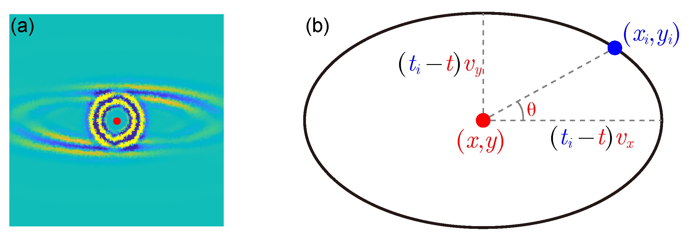
Figure 1. (a) Elastic wave propagation when the source position is a red dot in an anisotropic object, whose lateral elastic wave velocity is higher than that in the vertical direction. (b) An elliptical wave having a source at the location ( x , y ) at time t arrives at the sensor ( x i , y i ) at time t i . The horizontal and vertical velocities of the elliptic wave are v x and v y , respectively.
Applsci 12 11081 g001
Figure 2. Illustrative figure of the simulated AE signal. The presence of noise in the AE signal changes the signal arrival time, which is determined by the threshold.
Applsci 12 11081 g002
Figure 3. Illustrative figure showing the numerical experiment settings. The signal arrival time measured through the numerical experiment was obtained from the ellipse, where the elliptical wave initiated by the crack at the red dot reached the sensor position, which is the blue dot.
Applsci 12 11081 g003
Figure 4. Numerical experiment setting for solving Equation (8). When the source is at the red dot (position 4), an elliptical acoustic wave propagates, and the signal is measured at the blue dot.
Applsci 12 11081 g004
Figure 5. PLB experiment settings. (a) CFRP plate with AE sensor attached. (b) Desktop that collected AE signals measured by sensors. (c) Connector for connecting PAC board and sensor. (d) PAC’s Express-8 board. (e) PAC’s AE sensor (model: R15i-AST).
Applsci 12 11081 g005
Figure 6. Numerical experiment results with noise ASNRs 10, 30, and 50 and without noise. Here, ASNR is defined as in Equation (7). For simplicity of notation, the ASNR in the absence of noise is expressed as . The estimated location is represented in (ad), where ASNR is 10, 30, 50, and , respectively. The black dots are for sensor positions, while red dots represent crack positions. The blue plus sign (+) and blue cross mark (x) denote the estimated crack positions for λ = 0 and λ 0 , respectively. The relative error for noise is shown in (e) with a blue plus sign (+) when λ is zero and blue cross mark (x) when λ is non-zero.
Applsci 12 11081 g006
Figure 7. Results of elastic wave numerical experiments using various thresholds to obtain TOA. Estimated positions are denoted as (ad) at threshold levels of 5, 10, 15, and 20 dB, respectively. The black dots are for sensor positions, while red dots represent crack positions. The blue cross mark (x) denotes the estimated crack position. The relative error for noise is shown in (e).
Applsci 12 11081 g007
Figure 8. Result figures of PLB testing on CFRP with six different PLB positions, which are shown as red marks in (af). The estimated locations from (a) to (f) are indicated by blue plus signs (+), and the positions of the sensors are indicated by black dots. Relative errors for all six different PLB positions are shown in (g).
Applsci 12 11081 g008
Table 1. The used measurement variable values of the signal collector: sample rate, threshold value, digital filter frequency, PDT, HDT, HLT, and max duration time.
Sample RateThresholdDigital FilterPDTHDTHLTMax Duration
   (Microseconds)(Milliseconds)
2 MSPS40 dB20 kHz–1 MHz6015010,00010
Publisher’s Note: MDPI stays neutral with regard to jurisdictional claims in published maps and institutional affiliations.