Article

Determination of the Filler Concentration of the Composite Tape

1
Faculty of Mechanics and Technology, Rzeszow University of Technology, ul. Kwiatkowskiego 4, 37-450 Stalowa Wola, Poland
2
Department of Development and Technical Policy, JSC “Ukrainian Railway”, Jerzy Giedroyc Str. 5, 03150 Kyiv, Ukraine
3
Department of Wagons, Ukrainian State University of Science and Technologies, Lazaryana Str. 2, 49010 Dnipro, Ukraine
*
Author to whom correspondence should be addressed.
Appl. Sci. 2022, 12(21), 11044; https://doi.org/10.3390/app122111044
Submission received: 12 October 2022 / Revised: 26 October 2022 / Accepted: 28 October 2022 / Published: 31 October 2022
(This article belongs to the Section Mechanical Engineering)

Abstract

:
For the first time, a theoretical dependence was obtained to determine the filler concentration of the composite tape. On the basis of this dependence, a composite tape with variable mechanical and tribological properties can be obtained. It is proposed that the composite tape is welded onto the cylindrical surface of the central bowl of the rail truck bolster. The bench tests made it possible to determine the degree of wear of the central bowl of the rail truck bolster by means of a welded composite tape. The wear value of the central bowl of the rail truck bolster with welded-on composite tapes is 0.15–0.18 mm per 10,000 km of a freight car’s mileage. The predicted service life of the central bowl of the rail truck bolster with a welded-on composite tape is 320–420 thousand km.

1. Introduction

The technical condition of freight cars has a particular impact on the safety of railway traffic as well as the technical and economic indicators of the functioning of railway transport [1,2,3,4]. In order to improve the technical and economic indicators, the possibility of increasing the mileage between the repairs of freight cars without increasing the risk of violating the safety of railway traffic is considered [5,6,7,8].
One of the main resource-determining components of freight cars is the central bowl of the rail truck bolster (CBRTB), the technical condition of which determines the service life of the freight car as a whole. During the operation of freight cars, CBRTB wear is unevenly worn, which is related to the intensity of the wagons passing on tracks with small radius curves and, as a result, CBRTB requires premature repair due to the state of wear and tear. During the examination of the bolsters, it was found that the wear depth of the CBRTB abutment surfaces of the inner flanges increased sharply. This is due to the increase in the speed of the trains, which leads to an uneven increase in the loads on the freight car bogie. The analysis of the operating conditions and operating results of a freight car bogie made of 20GL, 20FL, and 20GFL low-alloy steels, belonging to the ferrite and perlite class, showed [9,10,11,12] that these parts during operation under dry friction conditions and the presence of high contact and impact loads have low wear resistance with an intensity of wear of working surfaces equal to 1.2–2.0 mm per 100,000 km of mileage. The use of low-carbon and low-alloy welding materials for CBRTB repair provides a repair mileage of only 160 thousand km, which corresponds to 2 years of operation [13,14]. CBRTB is repaired by overlapping the surface more than 10 times over its service life.
It is proposed that the wear of the CBRTB in [14,15] is reduced using different methods of repair and the installation of wear-resistant steel gaskets.
The experience of using the central bowl surface of the rail truck bolster and the installation of wear-resistant elements on them showed [11,14,15] that there is no universal, effective, and reliable protection against wear during friction. The presence of shock loads in the contact zone of the bolster parts did not allow the use of materials of high rigidity, which are characterized by increased fragility.
The use of other materials or developments is unknown to the authors.
The authors assume the possibility of using composite materials in the repair of CBRTB to increase the service life.
Studies on the use of composite materials in the repair of CBRTB to increase the service life have not been conducted.
Increasing the service life of the CBRTB with the use of composite materials is an urgent task, the solution to which should be based on the use of materials with high mechanical and tribological properties.
In addition, a composite tape can be made with the necessary mechanical and tribological properties, which is attached to the surface of the CBRTB by means of contact welding. Regarding contact welding, it should be noted that this method is not widely used. Although it is easy to use and, in principle, does not require special equipment—that is, industrial transformers and other means of freight car repair enterprises can be used—nevertheless, this method has not become widespread. It should also be noted that the ratio of the content of the matrix and the filler must be established in the composite tape.
Let us analyze the literature in which the quantitative content of the matrix and the filler of the composite material was studied.
The articles [16,17,18,19,20,21,22,23] provide an overview of journal publications related to multifunctional composite materials and structures.
On the basis of studying the elastic properties of composite materials and using a linear approximation of the displacement field, the filler and matrix ratio was determined at the boundary of the defective weld [24]. However, the optimal quantitative ratio of the filler and matrix is not presented.
The transverse strength of the composite material is investigated and it is concluded that the maximum strength of the composite material can be reasonably well estimated without using any experimental data [25]. However, the concentration ratios are not presented in the work.
Jiang et al. [26] proposed a new multiscale synergistic modeling structure combining the microscale and mesoscale to predict the damage behavior of a two-dimensional triaxial woven composite. The proposed multiscale structure provides a reliable tool only for future systematic studies of the level of composite materials that comprise aircraft structures.
The prediction of failure of the composite material, mainly based on the properties of the filler and matrix, is given in article [27]. The prediction is made using the bridging model and only contains composite fracture analysis.
Kanaoun [28] applied the effective field method to calculate the general physical and mechanical properties of composite materials consisting of a homogeneous matrix and a set of isolated inclusions (two-phase media). In this work, the effective field method was applied to improve the predictions of the effective properties of matrix composites in the region of high-volume concentrations of inclusions.
The strength of the composite material was predicted taking into account the stress concentration factor in the matrix, the plasticity of the matrix, and the residual thermal stresses in the components [29]. This article only presents the design methodology.
To predict the strength of a composite material using information about its components, in article [30], experiments are presented to study the strength of a composite material, which, together with other initial properties, is used as input data to predict the strength of various composites. However, the relationship between the matrix and the filler is not presented in this work.
Lapčík et al. [31] showed that both fillers (mica and wollastonite) trigger an increase in the Young’s modulus of elasticity with an increasing filler concentration in the matrix of HDPE composites. However, the theoretical relationship is not shown.
Composites integrating metallic particles are considered [32]. The paper analyzes the effect of the concentration and orientation of composite particles on the process and manufacturability. In this work, there are no theoretical dependences for determining the concentrations of the matrix and filler.
Marghalani [33] studied the effect of various sizes and shapes of fillers on the surface roughness of experimental series of resin-composite materials. In this case, only the results of experimental studies are presented.
Practically, in all studies, a certain range of filler concentration was taken, and the mechanical properties of the composite were studied [34,35,36,37].
To assess the mechanical properties of the composite systems, many different micromechanical models have been proposed [38,39,40,41]. According to such models, the physical and mechanical properties are determined.
The preparation and properties of the Fe-Cr-Ni group of metals were studied in [42,43,44,45,46]. However, these studies and others lack data on the properties of composite tapes.
In this regard, it should be noted that there is no theoretical model in the literature for determining the filler concentration in the composite material (tape). Therefore, a theoretical study is necessary to obtain the dependence of the filler concentration on the composite tape and to perform experimental studies to verify the adequacy of the theoretical model obtained.
The aim of this article was to determine the filler concentration of the composite tape.
The research methodology was based on the theory of logic, the theory of dimension, and the theory of wear.
The scientific novelty lies in the fact that, for the first time, a theoretical model was obtained to determine the filler concentration in a composite tape.
The use of a theoretical model to determine the filler concentration in the composite tape will reduce the wear of the friction surfaces. The results of the experimental studies can be used in the railway in the repair of the CBRTB.

2. Materials and Methods

CBRTB operational wear tests made it possible to construct wear charts, which were revealed in 95% of the cases of the experimental group of freight wagons. At the same time, five freight wagons were not included in any of the subgroups due to the lack of the indicated regularity of CBRTB consumption. The CBRTB consumption charts of the experimental subgroups of freight wagons are shown in Figure 1. The axis OX is directed along the cross-section of the freight wagon, and the axis OУ is directed in the direction perpendicular to the axis OX.
In Figure 1, one can see the characteristic uneven wear of the CBRTB of the experimental group of freight cars, leading to a reduction in the service life and setting of the freight car for premature repairs.
The wear of the center plate of the body of the freight car was not plotted, as no uneven wear was observed.
As shown by the results of CBRTB wear tests, it is necessary to increase the wear resistance of the material, ensuring the even distribution of wear during operation. After achieving an even consumption of CBRTB, it will be possible to guarantee the repair mileage of freight cars at the level of 300 thousand km, without carrying out premature repairs, and thus reducing the financial costs of maintaining freight cars.
The CBRTB wear diagrams of the experimental group of freight cars (Figure 1) indicate the necessity of using materials with discrete values of strength properties along the diameter, which will ensure even wear. This means that, in order to increase the repair life of the CBRTB during production or repair, it is necessary to set a discrete hardness of the material along the diameter.
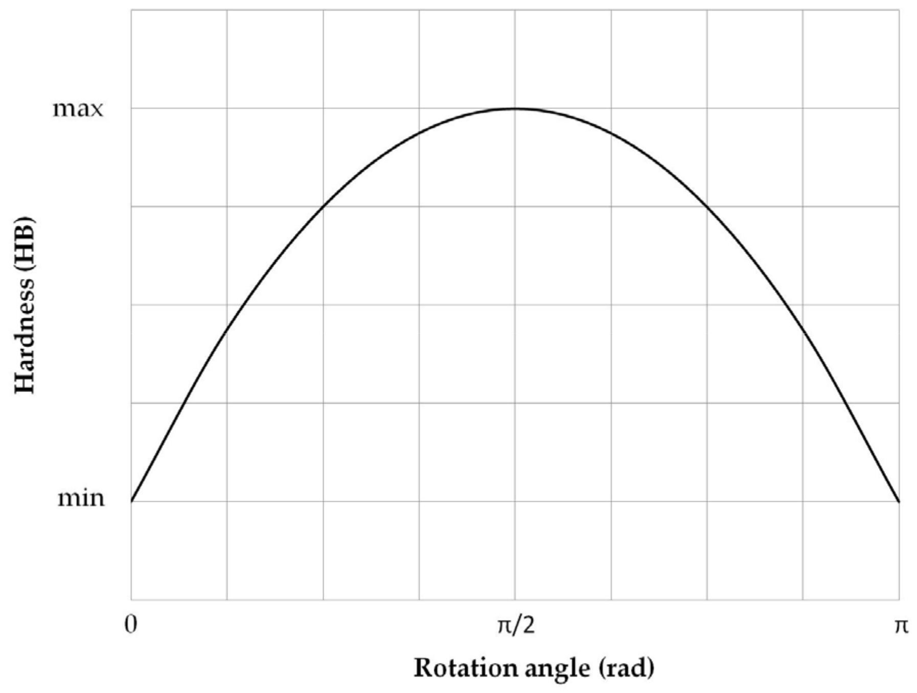
In this paper, it is proposed that the discrete hardness of a material is determined by the diameter of the CBRTB (during manufacture or repair), as shown in Figure 2. Moreover, such a distribution of the hardness of a CBRTB material in terms of the diameter during production or after repair will correspond to the wear graphs shown in Figure 1.
Such a distribution of the hardness of the CBRTB material according to the diameter can be achieved using the existing hardfacing and spraying technologies, but with a significant complexity of the technological process and extension of the repair time itself. In the production of discrete CBRTB hardness, there will also be a problem related to the complication of the technological process.
The methods of surfacing and spraying parts of freight cars belong to the group of methods in the liquid phase, the main and significant disadvantage of which is a significant thermal effect, both on the base material and the coating; in addition, there is the disadvantage of the need for subsequent machining to obtain standardized dimensions.
The contact welding of composite materials is more promising. We can weld various materials: steel or powder tape of the required composition, steel or powder wire, and firing powder materials.
The advantages of contact welding are: no parts need heating up, hardening of the base layer and coating directly during welding, 3–4-fold reduction in filler material consumption compared to arc welding, high efficiency, energy saving burnout, no burnout of alloy elements, adjustable welded layer in the range of 0.1–5.5 mm. This method does not affect the environment or the health of the operator. This method is most widely used to rebuild and strengthen shaft parts. The reinforcement of wear-resistant materials on sleeves by contact welding has practically not been studied.
The contact welding of wear-resistant powder materials, pre-formed composite strips, can become an effective way to increase the MTBF of CBRTB.
A feature of welding tapes with a flux core is that when heated over the entire thickness of the layer, due to the many transitional resistances inside it, the adjacent part of the part also heats up. Depending on the melting point ranges, uneven changes occur in the various components of the composite material. The refractory particles remain unchanged or crushed; medium-melting, plastically deformed and sintered; and low-melting, as they melt and fill the pores between the particles with a higher melting point. The layer to be welded almost always remains heterogeneous and consists of the same particles as the original composite material.
The paper proposes the determination of discrete mechanical and tribological properties by the diameter of CBRTB (during production or repair). For this purpose, it is proposed that a composite tape is used. This tape is welded using butt welding.
To ensure the sufficient adhesion of the composite strip to the cylindrical surface of the CBRTB, the pressure on the roller electrode should not be less than 60 MPa, and to prevent a significant reduction in the thickness of the strip, it should not exceed 80 MPa. The welding speed of the composite strip on the cylindrical surface of the CBRTB is in the range of 0.5–0.8 m/min.
In order to ensure the required abrasion resistance of the composite tape, the value of the matrix hardness should be in the range of 300–400 HB. To achieve these conditions, the matrix must have an austenitic and martensitic structure.
From the point of view of functional properties for the repair of the CBRTB and the formation of a composite tape according to the technical and economic criteria, carbides are the most expedient solid material. At the same time, chromium carbides (Cr3C2) and titanium carbides (TiC) were purchased for the manufacture of wear-resistant belts, materials, and coatings for practical use. These carbides have sufficient electrical conductivity and wetting with iron group metals, making them suitable for electric welding or moxibustion methods.
According to technical and economic criteria, it is recommended that iron is used as the matrix material (for example, iron powder 7439-89-6), which has high physical, mechanical and technological properties. The carbon content of 0.25% in the 7439-89-6 powder makes it possible to form hardened structures during the contact welding of the CBRTB, which increases the cylindrical wear resistance of the cylindrical working surface. In the composite tape, the fillers used are chromium carbide powder 12012-35-0 and titanium carbide powder 12070-08-5.
The production of composite tapes is a rather complicated process with the thermo-mechanical interaction of the given components. In order to improve the formation of strong bonds and the necessary electrical conductivity of the initial mixture, as well as the sufficient plasticity of composite tapes, this study proposes to introduce chromium and nickel into their content.
The increased activity powders of composite tape during sintering or processing during welding is associated with an excess supply of surface energy, which is due to the presence of a high density of dislocations in the crystal lattice, and the occurrence of relaxation processes, which additionally provide free energy, thereby helping to increase the diffusion activity.
As a result, the metal matrix of the composite tape will consist of a ternary alloy, which contains: powder based on iron, chromium, and nickel. The following concentration distribution was applied in the work: 70% Fe, 20% Cr, 10% Ni.
The wear resistance of the welded material of the composite tape depends on both the composition and rigidity of the matrix and the volumetric content of the filler. If its content is insufficient, the matrix is subject to wear, followed by the crumbling of the filler, and with an excess amount of the filler, the increased wear of the matrix is associated with increased porosity, and the possible spalling of the filler. Thus, the content of the wear-resistant phase in the composite tape should correspond to the distance between particles, approximately equal to the average particle diameter.
The performance of a composite tape is associated with the thermomechanical compatibility of the phases included in the material, and the thermomechanical compatibility of such phases depends on the thermal expansion coefficients of the matrix materials and the dimensions of the fillers.
Since the process of creating a composite coating takes place in two stages (creating a composite tape and its direct welding on the cylindrical surface of the CBRTB), the mutual thermal interaction of the phases can be considered jointly in the process of thermomechanical interaction similar to the process of composite strip production (rolling the powder mixture on rolls and then sintering in an inert atmosphere furnace), and in the contact welding process.
As noted earlier, the wear process of the CBRTB is varied (uneven). That is, welding a more wear-resistant composite tape to the cylindrical surface of the CBRTB will allow the wear rate to equalize at all its points, reduce the amount of wear, and thereby increase the service life of the CBRTB.
The selection of the required properties for each point of wear of the cylindrical surface of the CBRTB should be based on changes in the filler concentration of the composite tape.
Based on the wear of the CBRTB and the proposed hardness distribution (Figure 1 and Figure 2), we determine the concentration of the composite tape filler for each point on the cylindrical surface of the CBRTB.
The regularity of the required distribution of the filler concentration in the composite tape along the diameter of the bolster of the CBRTB is determined. Proceeding from the fact that the filler concentration per unit length by diameter is proportional to the concentration that is necessary to obtain such a wear-resistant and hardened layer, each point of the cylindrical surface of the CBRTB would have the same wear rate, i.e.,
d C d l = k C ,
where C is the filler concentration in the composite tape; k is the coefficient that depends on the properties of the interacting materials of the center plate of the body and the bolster of the CBRTB. This coefficient is proposed to be determined by the physical, mechanical and tribological properties of the center plate of the body and the CBRTB:
k = f K 1 · H 1 K 2 · H 2 ,
where f is the coefficient of friction;   H 1 ,   H 2 are the hardness (or microhardness) of the center plate of the body and the CBRTB, respectively;   K 1 ,   K 2 are elastic constant coefficients for the material of the center plate of the body and the CBRTB, respectively, which are determined by the expressions:
K 1 = 1 μ 1 2 E 1 ;               K 2 = 1 μ 2 2 E 2 ,
where μ 1 ,   μ 2 are Poisson’s ratios for the material of the center plate of the body and the CBRTB, respectively;   E 1 ,   E 2 are the modulus of elasticity of the material center plate of the body and the CBRTB, respectively.
Then, expression (2) will have the form
k = f E 2 1 μ 1 2 H 1 E 1 1 μ 2 2 H 2 .
The value of the elastic modulus of the composite tape can be determined by the following formula:
E 2 = E M 1 C F + E F C F ,
where
  • C F is the filler concentration of the composite tape;
  • E M is modulus of elasticity of the composite tape matrix;
  • E F is the modulus of elasticity of the filler of the composite tape.
We also write an expression for finding the hardness of a composite tape:
H 2 = H F H M + H F C F H F H M H M + H F + C F H F + H M ,
where
  • H M is a matrix hardness;
  • H F is the hardness of the filler.
Then, expression (4) will take the following form:
k = f E M 1 C F + E F C F 1 μ 1 2 H B 1 H M + H F + C F H F + H M E 1 1 μ 2 2 H F H M + H F C F H F H M .
By integrating the differential Equation (1) with the initial conditions (point 0, Figure 1):
l = 0 ,   C F = C F 0 ,
as a result, we have:
l n C F 0 C F = k l ,
where
  • C F 0 is the initial concentration of the filler of the composite tape;
  • l is the circumference of the CBRTB, which can be determined by the formula:
l = φ d 2 ,
where
  • d is the diameter of the CBRTB;
  • φ is the angle for the corresponding point, which is shown in Figure 1.
As a result, we have an expression for determining the filler concentration:
C F = C F 0 · e k l .
Furthermore, we write down the dependence for the filler concentration of the composite tape on the properties of the materials of the center plate of the body and the CBRTB (expression (7)):
C = C F 0 · e x p f E M 1 C F + E F C F 1 μ 1 2 H 1 E 1 1 μ 2 2 H F · H M + H F + C F H F + H M H M + H F C F H F H M d 2 φ .
The obtained dependence (11) characterizes the filler distribution of the filler concentration of the composite tape on the diameter of the CBRTB, taking into account the physical and mechanical properties of the center plate of the body and the properties of the composite tape.
Now, it is necessary to set the initial value of the filler concentration C F 0 . For this, the work carried out research on the hardness of the surface layers of the composite tape.

3. Results

3.1. Composite Tape Hardness Test

Composite tapes were tested on the prepared samples in accordance with the PN-EN ISO 6506-1: 2014-12 standard. The results were elaborated with the methods of mathematical statistics. The results are presented in Table 1.
The average hardness value of the composite tape of the composition Fe-Cr-Ni-Cr3C2 with a filler of up to 25% increases to a maximum, most likely due to the dissolution of Cr3C2 and the saturation of the matrix with carbon and the same chromium, followed by the formation of chemical reaction products. A further increase in the filler content in the formed layers leads to an increase in porosity with a decrease in hardness.
The average hardness value of the composite tape of the composition Fe-Cr-Ni-TiC with a filler of up to 20% increases to its maximum and then decreases. This decrease in hardness can be explained by an increase in porosity.
As a result, the minimum concentration of composite tape filler (Table 1) can be set at 10%. In this case, the hardness that will be provided is greater than that of the material, the CBRTB. The processing and mechanical characterization was carried out in Poland.

3.2. Theoretical Distribution of Filler in Composite Tape

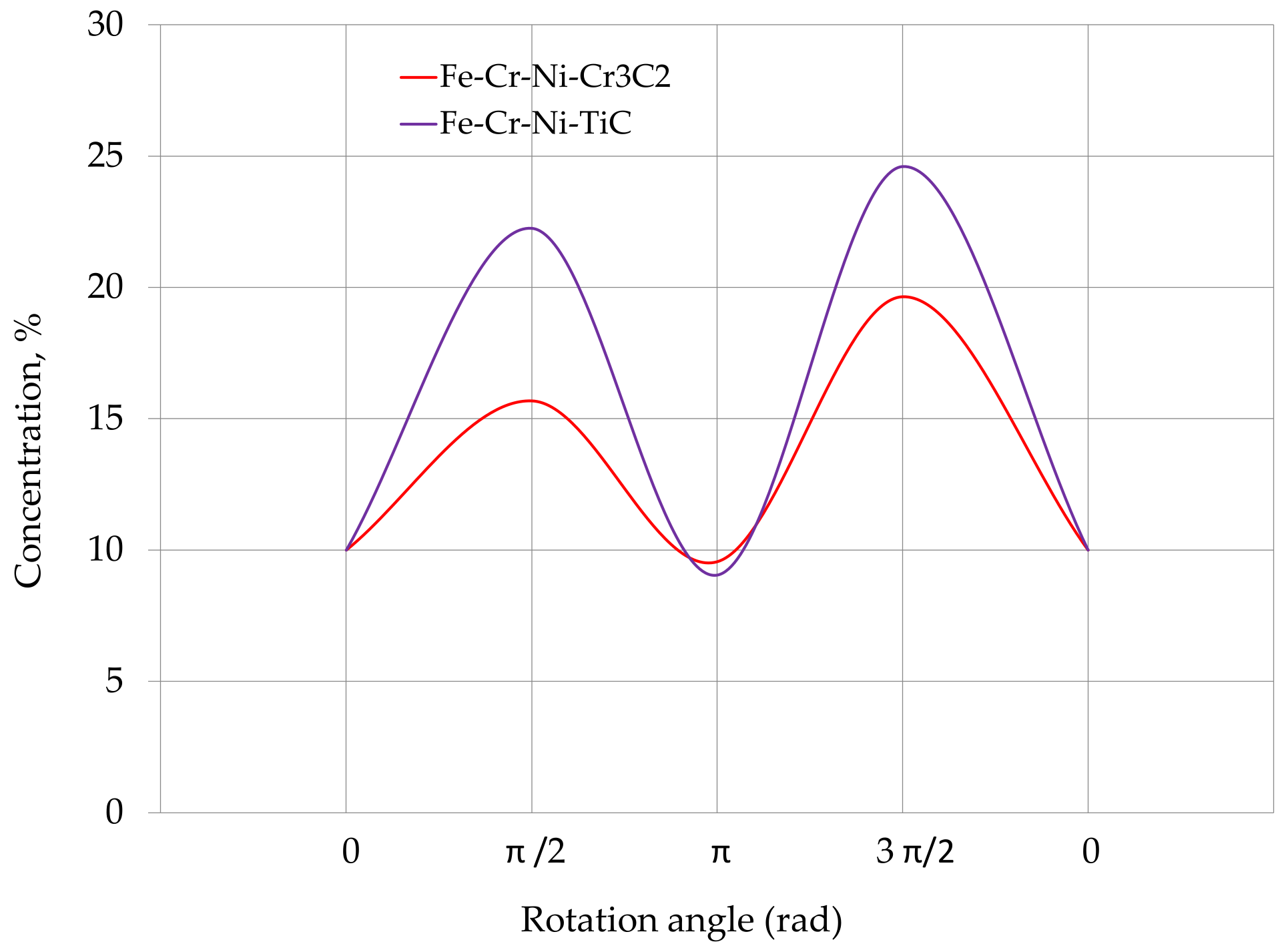
The theoretical distribution of the filler in the composite tape (expression (11)) along the length of the cylindrical surface of the CBRTB in function of the rotation angle is shown in Figure 3. It should be noted that for every π/4 in expression (11), the sign under the exponent changes to its opposite.

3.3. Theoretical Dependences of the Wear of a Composite Tape

The amount of wear of the CBRTB can be found by the formula:
δ = k ω d h d 0 Q L v ,
where ω is the circular alternating speed of rotation;   h is the height of the interaction of the cylindrical surfaces;   Q is loathe d;   L is the carriage path; d 0 is the center plate diameter; and v is the train speed.
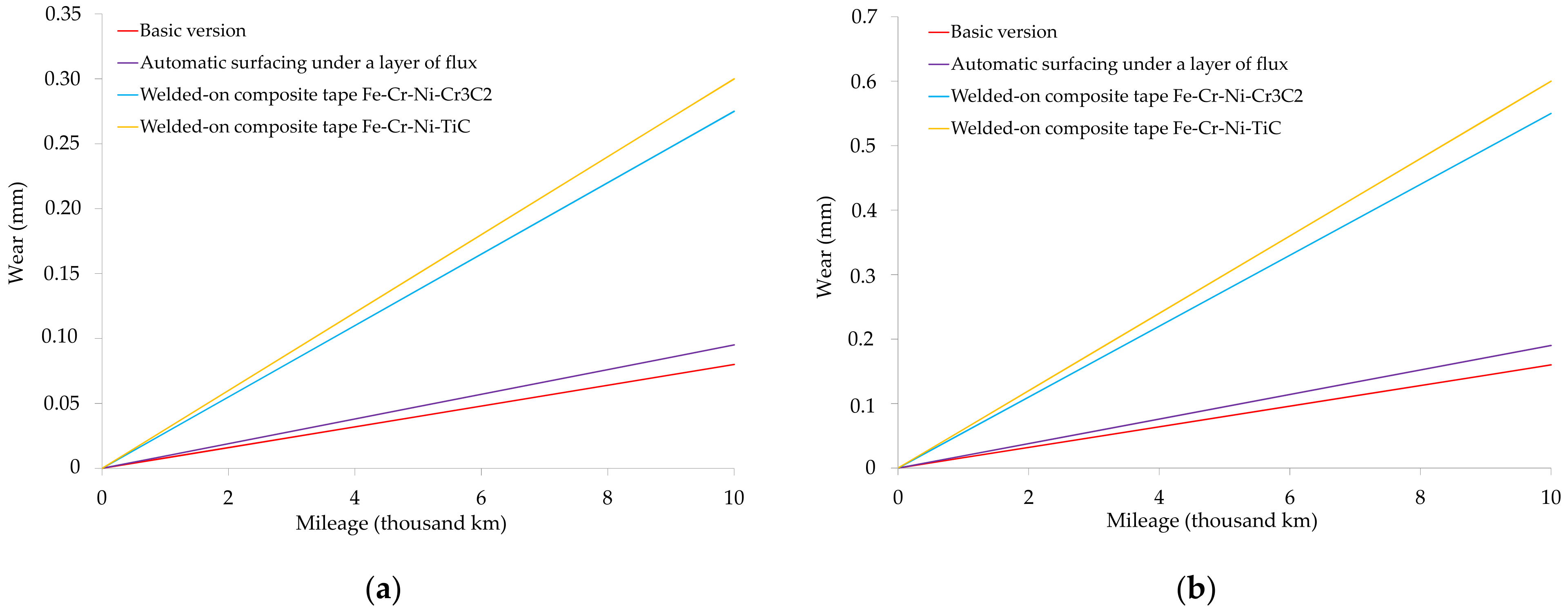
Based on (12), the theoretical dependences of the wear of the CBRTB were constructed (Figure 4).

3.4. Adhesion Strength of Composite Tapes

The adhesion strength of the composite tape with the cylindrical surface of the CBRTB was determined by the method of pulling off the pin. The scheme for determining the adhesion strength is shown in Figure 5.
The results of studies of the adhesion strength of tapes welded to specimens of steel 20GL are given in Table 2.
The obtained results (Table 2) allow us to conclude that the adhesion strength of the composite tape of the two compositions with the base metal is rather high. In the case of a composite tape of the composition Fe-Cr-Ni-Cr3C2, the adhesion strength with the base metal is 6.5% higher compared to the welded tape of the composition Fe-Cr-Ni-TiC and is 315.7 MPa.

3.5. Experimental Studies of Wear of the CBRTB

Bench studies of the magnitude of wear of the CBRTB were carried out on a test stand. The tests of the degree of wear were carried out on the bolster beams with the repaired CBRTB, the cylindrical surfaces of which were restored with a welded composite tape (with two compositions), and the CBRTB was also subject to research.
-
With installed wear-resistant steel elements;
-
Restored cylindrical surfaces by automatic submerged arc surfacing.
At the same time, the load–speed mode was close to the operating conditions with a full load of a freight car in a train of 12 units and in an empty state (due to the action of the tare weight).
The wear of the CBRTB was measured after every 2000 km of mileage. The wear value was measured with a caliper with an error of 0.1 mm.
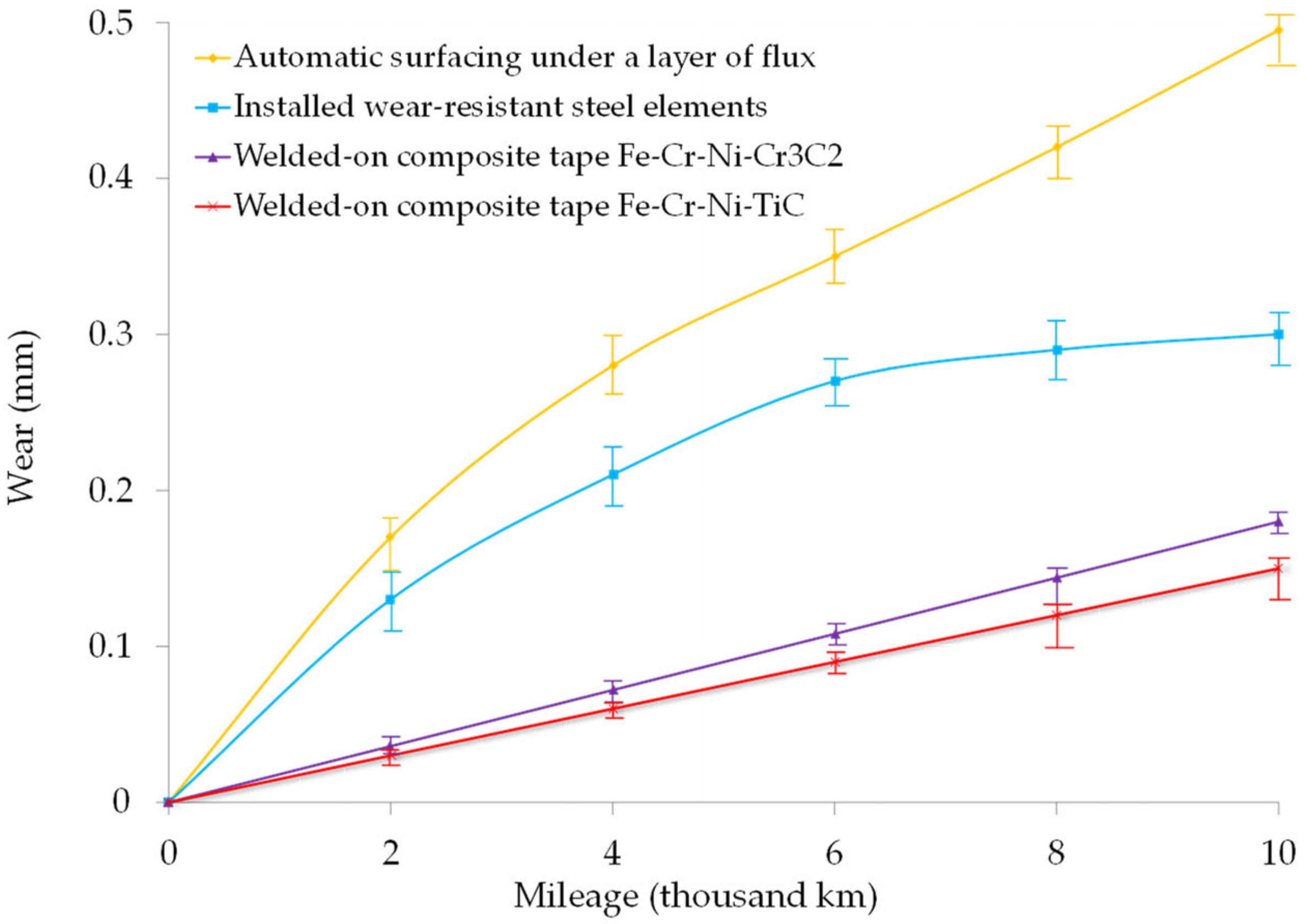
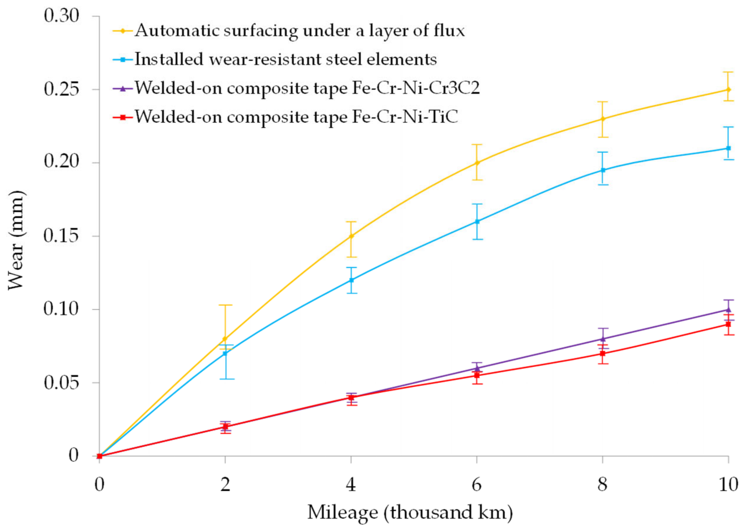
In Figure 6, the experimental dependences of the wear of the CBRTB when interacting with the center plate of the body are shown in function of the mileage, with the simulation of the case of a full load of a freight car (23.5 t/axle) in a train of 12 units. The processing and determination of wear was carried out in Ukraine.
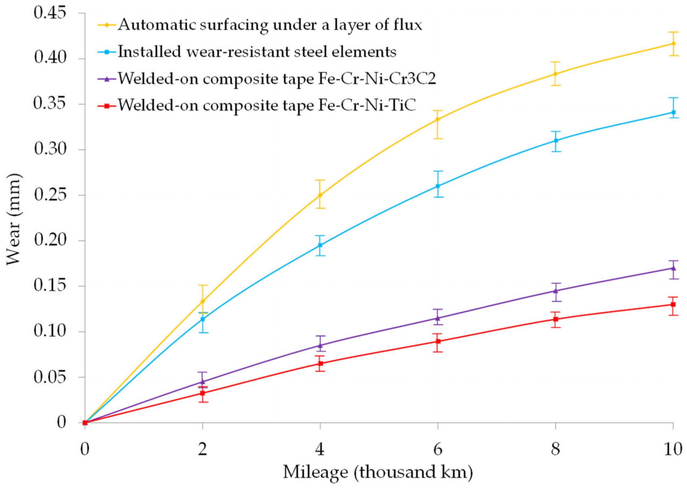
The experimental dependences of the wear value of the CBRTB when interacting with the center plate of the body, in function of the mileage with the simulation of the case of an mileage of an empty freight car in a train of 12 units, are shown in Figure 7.
When simulating the case of the mileage of an empty freight car (Figure 7), the wear value of the CBRTB when interacting with the center plate of the body in function of the mileage has a lower value than when fully loaded 1.4–2.1 times. One can envisage a similar tendency for the amount of wear to change in function of mileage, but the difference in values is slightly lower. Therefore, the amount of wear of the repaired surface of the CBRTB with welded composite tapes is 2.8–4.0 times less than the wear value on the CBRTB repaired by surfacing and 2.1–3.5 times less than the wear value of the CBRTB with installed wear-resistant elements. In turn, the wear value of the CBRTB with the installed wear-resistant elements is 1.14–1.25 times lower than that of the repaired CBRTB using automatic surfacing under a layer of flux.
To reproduce the pattern of the joint wear of the center plate, the wear of the center plate of the body was also recorded during the tests. Therefore, Figure 8 shows the dependence of the total wear of the center plate unit of a freight car on the mileage in both the case of a full load and as part of a loaded train.
From the given dependencies (Figure 8), it can be seen that the running-in process in the center plate assembly with all the repaired central bowls of the rail truck bolster proceeds up to 8000 km, as indicated by the total wear values of the connected surfaces. The total values of the wear of the center plate unit with a full load of the freight car, in function of the mileage, indicate that the units with the repaired CBRTB with automatic surfacing under a layer of flux (0.82 mm per 10,000 km of the mileage) have the greatest total wear. Center plate assemblies with a repaired CBRTB with wear-resistant elements have lower values of total wear—0.5 mm per 100,000 km of mileage. At the same time, the total amount of wear is 1.33–1.67 times lower compared to the unit with the repaired CBRTB by automatic surfacing. The value of the total wear of the surfaces of the center plate unit with the repaired CBRTB with welded-on composite tapes is 2.7–4.7 times lower than the value of the total wear of the units with the CBRTB repaired by surfacing, and 1.6–3.5 times lower compared to the value of the total wear of center plate units with the CBRTB, in which wear-resistant elements are installed.
Figure 9 shows the values of the total wear of the center plate unit of a freight car for the case of an empty load on the train in function of the mileage.
The provided data (Figure 9) are characterized by smooth dependences of the increase in the value of total wear of the center plate assembly for all the cases under consideration. In this case, the value of the total wear of the connected surfaces of the center plate unit, in function of the mileage, has lower values of 1.41–2.15 times than at full load. The value of the total wear of the center plate assembly with the repaired CBRTB with welded composite tapes is 2.4–4.3 times less than the value of the total wear of the center plate assembly with surfacing; 2.0–3.7 times less than the total wear of the center plate assembly with installed wear-resistant elements. The total wear of the center plate unit with the installed wear-resistant elements is 1.18–1.28 times lower than the total wear of the center plate with the use of the automatic surfacing under a layer of flux.

4. Discussion

The paper proposes the use of composite tapes for welding on the cylindrical surface of the CBRTB. The rational distribution of the filler concentration in the composite tape is considered, as a result of which a dependence is obtained that characterizes the required distribution of the filler concentration of the composite tape along the length of the CBRTB diameter, taking into account the mechanical and tribological properties of the center plate of the body and the composite material of the CBRTB.
Experimental studies make it possible to establish the appropriate level of service life of the CBRTB. The dependencies of the value of the wear of the CBRTB when interacting with the center plate of the body when simulating the case of the full load of a freight car in function of mileage (Figure 6) indicate that the most wear is observed in the CBRTB repaired by automatic surfacing under a layer of flux; the amount of wear is 0.5 mm per 100,000 km of mileage. It should be noted that the wear-resistant properties of steel elements have an improvement in wear values 1.31–1.65 times lower than the previously considered repaired CBRTB using automatic surfacing under a layer of flux. In the two cases considered herein, there is a running-in process of interacting surfaces up to 6 thousand km for the CBRTB with installed wear-resistant elements made of steel and above 10 thousand km for the CBRTB repaired by automatic surfacing under a layer of flux. The amount of wear of the repaired CBRTB with welded composite tapes in two cases (Figure 6) has a constant value with an increasing operating time, that is, there is no running process. The value of the surface wear value of the considered surface of the CBRTB repaired with welded composite tapes is 2.7–5.6 times less than the wear value of the central bowl of the rail truck support repaired by surfacing and 1.6–4.3 times less than the wear value with the installed wear-resistant elements.
The case of an empty freight car mileage on the train was also modeled. The amount of wear on the cylindrical surface of the CBRTB, in function of the mileage, has lower values than at full load (Figure 8). The wear of the repaired CBRTB with welded composite tapes is 2.8–4.0 times less than the wear of the CBRTB, repaired by surfacing; and 2.1–3.5 times less than the wear value of the CBRTB with installed wear-resistant elements.
The adequacy of the developed theoretical assumptions (Figure 4) and experimental tests (Figure 6 and Figure 7) are confirmed by slight deviations in the obtained wear values. The error does not exceed 6.25%.
The total wear value of the center plate assembly (Figure 8 and Figure 9) in function of the mileage of the unloaded freight car is less than 1.41–2.15 times than that when fully loaded. The total wear value of the center plate assembly with welded composite tapes is 2.4–4.3 times less than the value of the total wear with the repaired CBRTB surface; and 2.0–3.7 times less than the total wear of the CBRTB with the installed wear-resistant elements.

5. Conclusions

In the operation of freight cars, CBRTB wear is uneven, which is associated with the intensity of the passage of freight cars on tracks with small radius curves. In this case, there is an uneven increase in loads in the bogie of the freight car. In order to ensure uniform CBRTB wear and reduce the degree of wear, the use of composite tape with variable mechanical and tribological properties was proposed.
In this work, for the first time, a theoretical dependence was obtained to determine the filler concentration in the composite tape on the basis of which the specified mechanical and tribological properties can be obtained to ensure the uniform wear process of the CBRTB.
Bench studies made it possible to establish the appropriate level of the service life of the center plate units of freight cars. As such, when simulating the case of the full loading of a freight car (23.5 t/axle) as part of a train of 12 units, the amount of wear on the cylindrical surface of the CBRTB is 0.5 mm per 10,000 km of mileage. The amount of wear of the repaired CBRTB with welded composite tapes (Fe-Cr-Ni-Cr3C2, Fe-Cr-Ni-TiC) is 2.7–5.6 times less than the amount of wear of the CBRTB repaired by surfacing and 1.6–4.3 times less than the value of wear of the CBRTB with installed wear-resistant elements.
The total wear values of the center plate assembly at the full load of the freight car—in function of the mileage with the repaired CBRTB using the automatic surfacing method under a layer of flux—is 0.82 mm per 10,000 km of mileage; and is 0.5 mm per 10,000 km of mileage with the repaired CBRTB with wear-resistant elements. The total wear value of the center plate assembly with repaired CBRTB with welded composite tapes (Fe-Cr-Ni-Cr3C2, Fe-Cr-Ni-TiC) is 2.7–4.7 times less than the total wear value of the units with the CBRTB, repaired by surfacing; and is 1.6–3.5 times lower compared to the wear-resistant steel elements.
The adequacy of the developed theoretical assumptions and experimental studies was confirmed by minor deviations in the obtained wear values. The error does not exceed 6.25%.
The predicted service life of the center plate unit of the freight car with a welded-on composite tape Fe-Cr-Ni-Cr3C2 is 320 thousand km, and 420 thousand km of mileage with the welded-on composite tape Fe-Cr-Ni-TiC.

Author Contributions

Conceptualization, D.B., D.P., S.M., M.B. and L.M.; methodology, D.B., D.P. and L.M.; validation, D.B., D.P. and L.M.; formal analysis, D.B., D.P., M.B. and L.M.; investigation, D.B., D.P., S.M., M.B. and L.M.; resources, D.B., D.P. and L.M.; data curation, D.B., D.P. and L.M.; writing—original draft preparation, D.B., D.P., S.M., M.B. and L.M.; writing—review and editing, D.B., D.P., S.M., M.B. and L.M.; visualization, D.P., S.M., M.B. and L.M.; supervision, D.B.; project administration, D.B. All authors have read and agreed to the published version of the manuscript.

Funding

This research received no external funding.

Institutional Review Board Statement

Not applicable.

Informed Consent Statement

Not applicable.

Data Availability Statement

Data available on request.

Conflicts of Interest

The authors declare no conflict of interest.

References

  1. Peng, Z.; Lu, Y.; Miller, A.; Johnson, C.; Zhao, T. Risk Assessment of Railway Transportation Systems using Timed Fault Trees. Qual. Reliab. Eng. 2016, 32, 181–194. [Google Scholar] [CrossRef]
  2. Babyak, M.; Keršys, R.; Neduzha, L. Improving the dependability evaluation technique of a transport vehicle. In Proceedings of the Transport Means 2020—24th International Conference, Kaunas, Lithuania, 30 September–2 October 2020; pp. 646–651. [Google Scholar]
  3. Pshinko, O.M.; Ursulyak, L.V.; Zhelieznov, K.I.; Shvets, A.O. To the problem of train running safety. IOP Conf. Ser. Mater. Sci. Eng. 2020, 985, 012014. [Google Scholar] [CrossRef]
  4. Lingaitis, L.P.; Mjamlin, S.; Baranovsky, D.; Jastremskas, V. Experimental Investigations on Operational Reliability of Diesel Locomotyves Engines. Eksploatacja Niezawodnosc—Maint. Reliab. 2012, 14, 5–10. [Google Scholar]
  5. Baranovskyi, D.; Myamlin, S.; Kebal, I. Increasing the Carrying Capacity of the Solid-Body Rail Freight Car. Adv. Sci. Technol. Res. J. 2022, 16, 219–225. [Google Scholar] [CrossRef]
  6. Baranovskyi, D.; Muradian, L.; Bulakh, M. The Method of Assessing Traffic Safety in Railway Transport. IOP Conf. Ser. Mater. Sci. Eng. 2021, 666, 042075. [Google Scholar] [CrossRef]
  7. Lingaitis, L.P.; Mjamlin, S.; Baranovsky, D.; Jastremskas, V. Prediction methodology of durability of locomotives diesel engines. Eksploatacja Niezawodnosc—Maint. Reliab. 2012, 14, 154–159. [Google Scholar]
  8. Bulakh, M.; Okorokov, A.; Baranovskyi, D. Risk System and Railway Safety. IOP Conf. Ser. Mater. Sci. Eng. 2021, 666, 042074. [Google Scholar] [CrossRef]
  9. Shibo, W.; Yong, M.; Bing, T.; Li, P. Modeling and simulating of center plate of the body torsion behavior during bogie curve and turnout negotiation. J. Mech. Sci. Technol. 2014, 28, 2723–2732. [Google Scholar] [CrossRef]
  10. Olshevskiy, A.; Kim, C.W.; Yang, H.I.; Olshevskiy, A. Wear simulation for the centre plate arrangement of a freight car. Veh. Syst. Dyn. 2015, 53, 856–876. [Google Scholar] [CrossRef]
  11. Romero Navarrete, J.A.; Otremba, F. A variable friction centre plate. In IFToMM World Congress on Mechanism and Machine Science; Springer: Cham, Switzerland, 2019; pp. 3611–3620. [Google Scholar] [CrossRef]
  12. Poveda-Reyes, S.; Rizzetto, L.; Triti, C.; Shi, D.; Garcia-Jimenez, E.; Molero, G.D.; Santarremigia, F.E. Risk evaluation of failures of the running gear with effects on rail infrastructure. Eng. Fail. Anal. 2021, 128, 105613. [Google Scholar] [CrossRef]
  13. Gorbunov, M.; Kara, S.; Nozhenko, O.; Fomin, O.; Vaiciūnas, G.; Petrenko, V. Creation of the image of the new generation freight car bogie. In Proceedings of the Transport Means 2018—22nd International Scientific Conference, Trakai, Lithuania, 3–5 October 2018; pp. 1277–1283. [Google Scholar]
  14. Martynov, I.; Trufanova, A.; Shovkun, V. Construction of the simulation model “car railway track” for modeling the dynamic loading process of the boot node. MATEC Web Conf. 2018, 230, 101–115. [Google Scholar] [CrossRef]
  15. Anthony, L. US 20190106131 A1. Railway Truck Bolster Center Bowl Liner. Publication Apr 11, 2019. B61F 5/04 (20060101). Swoboda; Anthony, L. (Villa Ridge, MO). Available online: https://www.freepatentsonline.com/y2019/0106131.html (accessed on 11 October 2022).
  16. De Luca, A.; Caputo, F. A review on analytical failure criteria for composite materials. AIMS Mater. Sci. 2017, 4, 1165–1185. [Google Scholar] [CrossRef]
  17. Todor, M.P.; Bulei, C.; Kiss, I. An overview on fiber-reinforced composites used in the automotive industry. ANNALS Fac. Eng. Hunedoara—Int. J. Eng. 2017, 15, 181–188. [Google Scholar]
  18. Benzait, Z.; Trabzon, L. A Review of Recent Research on Materials Used in Polymer–Matrix Composites for Body Armor Application. J. Compos. Mater 2018, 52, 3241–3263. [Google Scholar] [CrossRef]
  19. Narayana, K.J.; Burela, R.G. A review of recent research on multifunctional composite materials and structures with their applications. Mater. Today Proc. 2018, 5, 5580–5590. [Google Scholar] [CrossRef]
  20. Gan, Y.X. A review of electrohydrodynamic casting energy conversion polymer composites. AIMS Mater. Sci. 2018, 5, 206–225. [Google Scholar] [CrossRef]
  21. Al-Mezrakchi, R.; Al-Ramthan, A.; Alam, S. Designing and modeling new generation of advanced hybrid composite sandwich structure armors for ballistic threats in defense applications. AIMS Mater. Sci. 2020, 7, 608–631. [Google Scholar] [CrossRef]
  22. Czech, K.; Oliwa, R.; Krajewski, D.; Bulanda, K.; Oleksy, M.; Budzik, G.; Mazurkow, A. Hybrid Polymer Composites Used in the Arms Industry: A Review. Materials 2021, 4, 3047. [Google Scholar] [CrossRef]
  23. Sharma, V.K.; Kumar, V.; Joshi, R.S.; Jain, S.; Kumar, P. A Review of Recent Research on Rare Earth Particulate Composite Materials and Structures with Their Applications. Trans. Indian Inst. Met. 2021, 74, 2569–2581. [Google Scholar] [CrossRef]
  24. Ghalandari, M.; Toozandehjani, H.; Mahariq, I.; Abeljawad, T. Determination of Composite Properties in the Presence of Fiber Deboning and Matrix Damage by Using the Method of Cell. Preprints 2020, 6, 2020090143. [Google Scholar] [CrossRef]
  25. Liu, L.; Huang, Z.M. Stress concentration factor in matrix of a composite reinforced with transversely isotropic fibers. J. Compos. Mater. 2013, 48, 81–98. [Google Scholar] [CrossRef]
  26. Jiang, H.; Ren, Y.; Jin, Q. A novel synergistic multi-scale modeling framework to predict micro- and meso-scale damage behaviors of 2D triaxially braided composite. Int. J. Damage Mech. 2021, 31, 108–141. [Google Scholar] [CrossRef]
  27. Huang, Z.-M. Constitutive Relation, Deformation, Failure and Strength of Composites Reinforced with Continuous/Short Fibers or Particles. Compos. Struct. 2020, 262, 113279. [Google Scholar] [CrossRef]
  28. Kanaoun, S.K. Effective Properties of Matrix Composite Materials with High Volume Concentrations of Inclusions (Effective Field Approach). In Continuum Models and Discrete Systems; Bergman, D.J., Inan, E., Eds.; NATO Science Series; Springer: Dordrecht, The Netherlands, 2004; Volume 158, p. 537. [Google Scholar] [CrossRef]
  29. Huang, Z.-M.; Liu, L. Assessment of composite failure and ultimate strength without experiment on composite. Acta Mech. Sin. 2014, 30, 569–588. [Google Scholar] [CrossRef]
  30. Huang, Z.-M.; Xin, L.M. Stress Concentration Factor in Matrix of a Composite Subjected to Transverse Compression. Int. J. Appl. Mech. 2016, 8, 1650034. [Google Scholar] [CrossRef]
  31. Lapčík, L.; Maňas, D.; Lapčíková, B.; Vašina, M.; Staněk, M.; Čépe KVlček, J.; Waters, K.E.; Greenwood, R.W.; Rowson, N.A. Effect of filler particle shape on plastic-elastic mechanical behavior of high density poly(ethylene)/mica and poly(ethylene)/wollastonite composites. Compos. B Eng. 2018, 141, 92–99. [Google Scholar] [CrossRef]
  32. Leon, A.; Perez, M.; Barasinski, A.; Abisset-Chavanne, E.; Defoort, B.; Chinesta, F. Multi-Scale Modeling and Simulation of Thermoplastic Automated Tape Placement: Effects of Metallic Particles Reinforcement on Part Consolidation. Nanomaterials 2019, 9, 695. [Google Scholar] [CrossRef] [Green Version]
  33. Marghalani, H.Y. Effect of filler particles on surface roughness of experimental composite series. J. Appl. Oral Sci. Rev. FOB 2010, 18, 59–67. [Google Scholar] [CrossRef] [Green Version]
  34. Gao, Y.; Picot, O.T.; Bilotti, E.; Peijs, T. Influence of Filler Size on the Properties of Poly(lactic acid) (PLA)/Graphene Nanoplatelet (GNP) Nanocomposites. Eur. Polym. J. 2016, 86, 117–131. [Google Scholar] [CrossRef]
  35. Fitriani, P.; Kwon, H.; Zhou, X.; Yoon, D.H. Joining of SiCf/SiC using a layered Ti3SiC2-SiCw and TiC gradient filler. J. Eur. Ceram. Soc. 2020, 40, 1043–1051. [Google Scholar] [CrossRef]
  36. Xiao, Z.; Ouyang, S.; Zhu, X.; Xu, W.; Wang, Z.; Shao, C. Investigation of Ti3AlC2 formation mechanism through diffusional reaction between carbon and Mo-modified Ti6Al4V. J. Eur. Ceram. Soc. 2020, 40, 1125–1131. [Google Scholar] [CrossRef]
  37. Guan, P.; Lei, J.; Zou, Y.; Zhang, Y. Improved Thermo-Mechanical Properties and Reduced Hydrogen Permeation of Short Side-Chain Perfluorosulfonic Acid Membranes Doped with Ti3C2Tx. Materials 2021, 14, 7875. [Google Scholar] [CrossRef]
  38. Halpin, J.C.; Kardos, J.L. The Halpin-Tsai equations: A review. Polym. Eng. Sci. 1976, 16, 344–352. [Google Scholar]
  39. Fornes, T.D.; Paul, D.R. Modeling properties of nylon 6/clay nanocomposites using composite theories. Polymer 2003, 44, 4993–5013. [Google Scholar] [CrossRef]
  40. Ciselli, P. The Potential of Carbon Nanotubes in Polymer Composites. Ph.D. Thesis, Technische Universiteit Eindhoven, Eindhoven, The Netherland, 2007. [Google Scholar]
  41. Eriksson, M.; Goossens, H.; Peijs, T. Influence of the Solidification Process on the Mechanical Properties of Solid-State Drawn PCL/Sepiolite Nanocomposite Tapes. Fibers 2020, 8, 70. [Google Scholar] [CrossRef]
  42. Ostash, O.P.; Zhmur-Klimenko, V.T.; Yarema, S.Y.; Yushchenko, K.A.; Strok, L.P.; Belotserkovets, V.I. Low-temperature cyclic crack resistance of weld joints of Fe-Cr-Ni and Fe-Cr-Mn steels. Sov. Mater. Sci. 1983, 19, 205–209. [Google Scholar] [CrossRef]
  43. Starikov, S.A.; Kuznetsov, A.R.; Sagaradze, V.V.; Gornostyrev, Y.N.; Pechenkin, V.A.; Stepanov, I.A. Formation of grain boundary segregations in alloy Fe-Cr-Ni during strong deformation and under radiation. Phys. Met. Metallogr. 2012, 113, 241–245. [Google Scholar] [CrossRef]
  44. Andreev, A.O.; Galkin, M.P.; Libman, M.A.; Mironov, V.D.; Petrovskii, V.N.; Estrin, E.I. Use of Laser Heat Treatment for Creating Gradient Materials Based on the Fe–Cr–Ni System. Met. Sci. Heat Treat. 2014, 56, 53–56. [Google Scholar] [CrossRef]
  45. McCafferty, E. A Recent Model of Passivity for Fe-Cr and Fe-Cr-Ni Alloys. In Surface Chemistry of Aqueous Corrosion Processes; SpringerBriefs in Materials; Springer: Cham, Switzerland, 2015. [Google Scholar] [CrossRef]
  46. Nguyen, T.D.; Zhang, J.; Young, D.J. Water Vapor Effects on Corrosion of Fe–Cr and Fe–Cr–Ni Alloys Containing Silicon in CO2 Gas at 818 °C. Oxid. Met. 2015, 83, 575–594. [Google Scholar] [CrossRef]
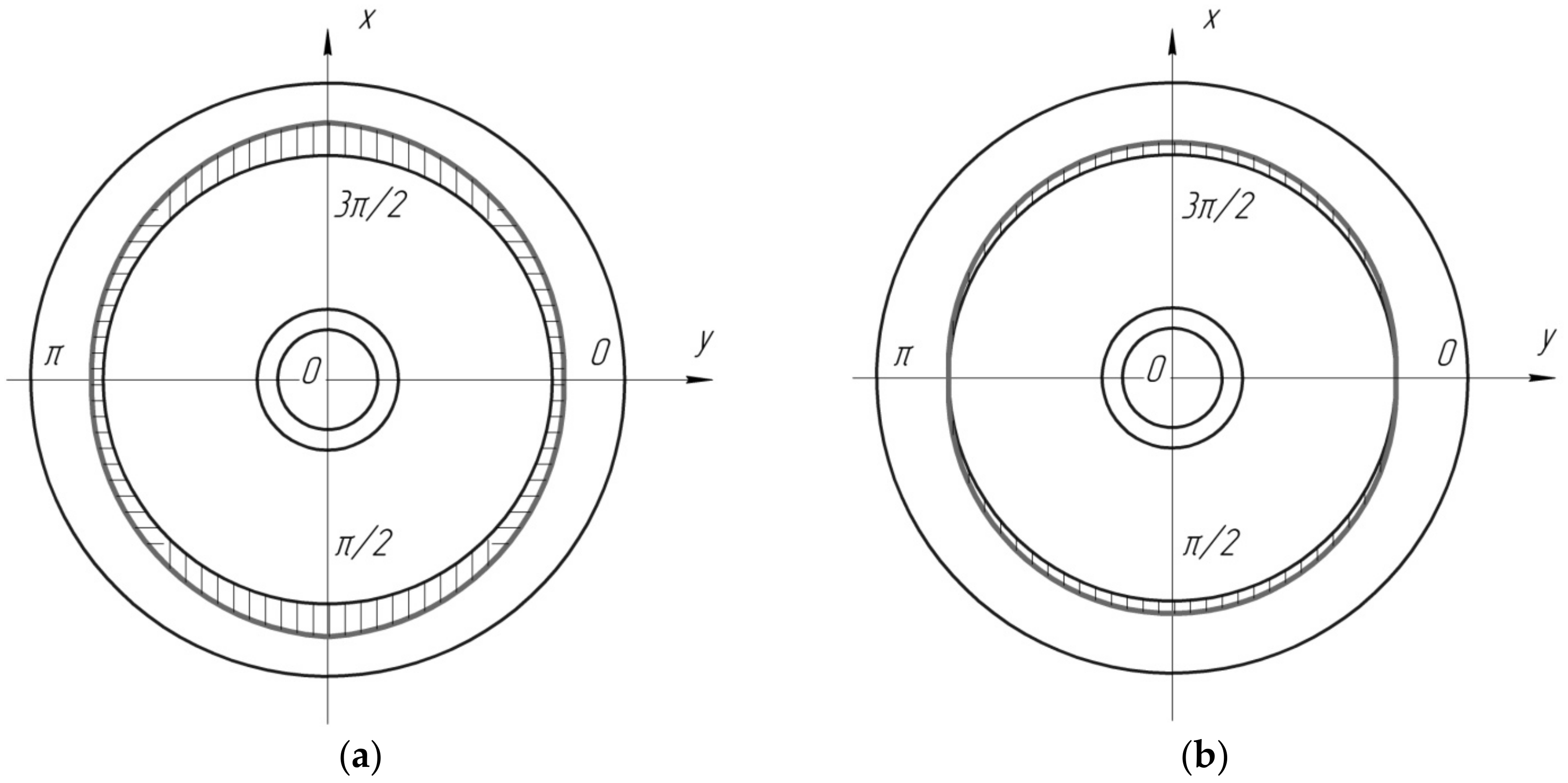
Figure 1. Diagrams of wear of the CBRTB after interaction with the center plate of the body: (a) In all directions; and (b) in two directions.
Applsci 12 11044 g001
Figure 2. Distribution of material hardness over the diameter of the CBRTB in function of the rotation angle.
Applsci 12 11044 g002
Figure 3. Dependence of the filler concentration in the composite tape along the length of the cylindrical surface of the CBRTB in function of the rotation angle.
Applsci 12 11044 g003
Figure 4. Diagrams of wear of the CBRTB after interaction with the center plate of the body in function of the mileage: (a) an empty freight car; and (b) a full load of a freight car.
Applsci 12 11044 g004
Figure 5. The scheme for determining the adhesion strength: (1) mandrel; (2) pin; (3) emphasis; (4) and composite tape.
Applsci 12 11044 g005
Figure 6. Experimental dependences of the wear of the CBRTB in function of the mileage.
Applsci 12 11044 g006
Figure 7. Experimental dependences of the wear of the CBRTB in function of the mileage of an empty freight car.
Applsci 12 11044 g007
Figure 8. Dependences of the total value of the wear of the center plate assembly for the case of a full load of a freight car on the mileage for the repaired CBRTB in function of the mileage.
Applsci 12 11044 g008
Figure 9. The total value of the wear of the center plate assembly for the case of an empty load of a freight car, in function of the mileage for the repaired CBRTB in function of the mileage.
Applsci 12 11044 g009
Table 1. Dependence of the hardness of the composite tapes of the filler concentration.
Composite TapeAverage Hardness, HB
Filler Concentration, %
101520253035
Fe-Cr-Ni-Cr3C2335344372395390382
Fe-Cr-Ni-TiC359374397387378366
Table 2. The results of studies of the adhesion strength of tapes welded to specimens of steel 20GL.
Composite TapeAdhesion Strength, MPa
Pin No.
12345678910Mean
Fe-Cr-Ni-TiC287 ± 2290 ± 2297 ± 3305 ± 2295 ± 1308 ± 2307 ± 2301 ± 1303 ± 1298 ± 2299.2 ± 1.8
Fe-Cr-Ni-Cr3C2308 ± 1309 ± 2329 ± 3315 ± 1322 ± 3328 ± 3320 ± 2308 ± 1306 ± 1312 ± 2315.7 ± 1.9
Publisher’s Note: MDPI stays neutral with regard to jurisdictional claims in published maps and institutional affiliations.