Article

Introducing Mobile Collaborative Robots into Bioprocessing Environments: Personalised Drug Manufacturing and Environmental Monitoring

1
Laboratory for Advanced Manufacturing Simulation and Robotics (LAMS), School of Mechanical and Materials Engineering, University College Dublin, D04 V1W8 Dublin, Ireland
2
National Institute for Bioprocessing Research and Training, A94 X099 Dublin, Ireland
*
Author to whom correspondence should be addressed.
Appl. Sci. 2022, 12(21), 10895; https://doi.org/10.3390/app122110895
Submission received: 30 April 2022 / Revised: 14 September 2022 / Accepted: 12 October 2022 / Published: 27 October 2022
(This article belongs to the Section Mechanical Engineering)

Abstract

:
Personalised therapeutic drugs are the future of the medical drug sector. For manufacturers, this will require the flexibility to produce many different unique batches within a given facility. This research paper aims to demonstrate the potential of mobile collaborative robots for improving current manufacturing practices in personalised therapeutics. The benefits and challenges of introducing robots in biologics are explored, including current practices, limitations, likely future practices, and the market outlook. Experiments demonstrating the application of a mobile collaborative robot to perform three different routine tasks is presented. These experiments include the transport of centrifugal tubes, manipulation of infusion bags, and scanning of Petri dishes for environmental monitoring. The investigations highlight the potential of collaborative mobile robotic platforms for automating the routine tasks carried out within the biomanufacturing sector.

1. Introduction

Collaborative mobile robots are currently finding applications in manufacturing, for example, in the semiconductor industry, thanks to their flexibility to carry out a broader range of tasks than traditional robots while still having their advantages over human operators [1]. One specific condition that mobile robots can support in the semiconductor industry is the requirement to maintain very high cleanliness levels. In multiple studies focusing on contamination sources, humans are repeatedly identified as one of the leading causes of contamination [2,3,4], so reducing human presence through the use of mobile robots can reduce the contamination risk significantly.
Similar advantages could be realised in the biomanufacturing industry. However, this industry is much slower to adopt the new technology due to the highly regulated nature of the biomanufacturing sector [5] and the requirements of Good Manufacturing Practice (GMP) compliance. The BioPhorum Operations Group (BPOG) has produced a technology roadmap with contributions from more than a dozen leading companies, which outlines objectives to increase the use of robots in biomanufacturing to reduce labour cost, reduce errors, and improve overall cost and reliability [6]. This clearly highlights the will to increase the use of robots in this sector, in addition to the lack of existing examples in this sector.
Currently, research is being carried out to automate some of the routine activities in biomanufacturing, such as handling of samples [7,8], analysis of samples [9,10] and weighing and dispensing of media [11,12]. These activities are carried out using robots with a fixed base. The use of robots in biomanufacturing is anticipated to improve product quality and reduce cost by reducing human error and contamination. Cell therapy firms are already looking for alternative production methods, such as cell shuttle platforms, to replace conventional manufacturing methods [7]. A mobile robot chemist [8] at Liverpool University is a testament to recent progress in an area similar to biomanufacturing; this mobile robot has been carrying out laboratory experiments that humans otherwise do. The lack of development and investment in software and hardware due to the need for extensive validation is one of the limiting factors preventing the penetration of mobile robots into the biomanufacturing sector.
With the advancement of biotechnology, molecular medicine, and biomanufacturing, the concept of personalised medicines, especially gene therapy and autologous cell-based therapies, are becoming increasingly relevant. Personalised medicine is tailored for a particular patient or a small group of patients. These medicines are also called precision medicine. The treatment is customised based on the genotypic or phenotypic information about the patient [13,14,15,16,17]. In short, for a given disease, a particular treatment is decided based on the data about the patient. Affordability and hurdles in scaling up are major concerns in the personalised therapeutic sector [18,19,20,21], and like any product, the manufacturing cost is one of the factors affecting the price of personalised medicines. The current cell lines used for viral vector-based production can manage a moderately sized batch of a few hundred to thousands of doses, but scaling the production to a larger population above 10,000 individuals is a challenge. Conversely, some rare drugs might be required by less than 100 patients per year, making them commercially unattractive to manufacture [22]. Applying a robotic solution could make the production of very small batches commercily viable. Collaborative robots are suited for flexible small batch production with different product variants produced in each batch [23]. Similarly, mobile collaborative robots could replace the manual labourers performing routine repetitive tasks. This could bring down the production cost making large scale flexible manufacturing viable.
There are personalised medicines developed for a wide variety of diseases, such as Mycobacterial Pulmonary Disease [14], different types of cancers [24], rheumatoid arthritis [25], diabetes mellitus [26], etc. Some of the personalised medicines that have passed FDA approval are given in [27]. The cost of such medicines can be very high. For example, the cost of manufacturing one dose of allogeneic therapy would be between 1030–1260 euros, while the cost of autologous therapy would be 2500–3360 euros [28]. However, the cost of certain personalised biologic medicines can be above 90,000 euros/millilitre [29]. The overall cost for CAR-T cell-based therapies, if produced using the current manufacturing methods, would be between 139,000–280,000 euros [30].
Cell therapies use cells derived from the patient (autologous) or from a matched allogeneic donor [31]. In the former scenario, each container/batch in a manufacturing facility for autologous cell-based therapies can be unique with respect to the drug it holds. Therefore, the manufacturer must manage these unique drugs from cell harvest to delivery. Some of the methods and technologies required to produce autologous cell therapies via scaling out are bioreactors, microcarriers, cell separation, and cryopreservation [19,32]. Table 1 shows a list of different bioreactors used in cell therapy studies. A detailed list of bioreactors used for allogeneic cell therapy can be found in [33]. A list of Commercial bioreactors used for cell therapy-related studies can be found in Table 2.
One of the critical challenges in manufacturing personalised drugs, especially autologous cell therapies and other gene therapies, is related to logistics, including transport and storage [20,34]. Transport, in particular, relates to the following activities: (1) Timely transport of harvested cells to the cryopreservation centres in the manufacturing facility, (2) Transport of the cells within the manufacturing facility or from a stem cell facility for manufacturing, (3) Transportation of the final product to the health care facility. Transportation of the cells is challenging due to the requirement to control cell density, buffer composition, temperature, etc. [35]. Studies have shown that the viability declines as time goes by [36]. Hence, the timely delivery of the cells and the products in the correct transport media is of utmost importance for the success of a personalised drug. Although researchers have pointed out the importance of transportation and storage conditions for the viability of autologous cell-based drugs, there is no definitive guideline or standards for the transportation and storage [37,38].
Table 1. Types of bioreactors used in cell therapy studies.
Therapy TypeBioreactor SizeTypes of Reactors UsedReference
CAR-T therapies100–200 mLT Flasks, Static culture bags, rocking motion bioreactor[39]
Hematopoietic stem cell therapy3–550 mLPerfusion chamber, stirred tank, fluidised bed, fixed bed, airlift, hollow fiber [40,41,42]
Hematopoietic progenitor cell therapy173–600 mLStirred suspension, fixed bed reactor[43,44,45]
Mesenchymal cell therapy15 mL–5 Lfixed bed disposable reactor[46,47]
Table 2. Commercial bioreactors used for cell therapy studies.
Commercial BioreactorsBioreactor SizeReference
Ambr 15 cell culture system24–48 parallel, 10–15 mL micro bioreactors[39]
PBS-MINI MagDrive Bioreactor100–500 mL[43]
PALL iCELLi Nano1000 mL[48]
Current methods of preserving cells are labour intensive and need to be replaced with more efficient and cost-effective methods. As the personalised medical sector grows, it is expected that the manufacturer needs to produce a wider variety of drugs in small batches [29] and move towards truly personalised medicines where the medicine itself will be unique for each patient [17]. Improving commercial viability requires reducing production costs while maintaining the flexibility to produce a wide range of personalised batches, and mobile robots may contribute to this.
Bioprocessing environments are highly regulated to ensure that the manufacturing of drugs happens in an aseptic condition [49,50]. Cleanrooms are specially built areas where the environment is controlled to carry out aseptic production [23,24]. Hence, cleanrooms are a fundamental part of any biomanufacturing facility. Environmental monitoring is carried out to assess the cleanliness of biomanufacturing and medical device manufacturing environments [51]. Active air samplers, contact plates, settle plates, and particle counters are some of the methods used to monitor the cleanrooms. Air samplers, contact plates, and settling plates are used to capture, colonise, and count viable particles. Meanwhile, particle counters count the non viable airborne particles. Environmental monitoring samples in cleanrooms are currently collected manually by microbiologists. The overall process is labour intensive, requires a lot of time, is prone to human errors, and expensive. The total number of samples collected annually in a biomanufacturing facility can exceed several thousand [52]. In multiple studies focusing on contamination sources, humans are repeatedly identified as one of the leading causes of contamination [2,3,4].
Thus, biomanufacturing in general, and autologous manufacturing particularly, requires manual transportation and manipulation of many pieces of equipment and containers within the manufacturing facility, as well as completion of different environmental monitoring tasks and documentation of the tasks. These jobs, which are mundane in nature, add a lot to the manufacturing cost and are also a cause of contamination. Hence, there is a need to automate these tasks to improve production standards and reduce manufacturing costs. As a consequence, mobile robots could offer significant potential advantages in biomanufacturing processes.
Table 3 shows the number of Web of Science/Scopus indexed research articles related to biomanufacturing and personalised medicine. Numerous research works are carried out in the domain of personalised medicine. However, there is very little to no research work carried out in this area of application of mobile robots in personalised medicine and biomanufacturing. At the same time, there are several examples of applying mobile robots in the general manufacturing domain. Although the application of mobile robots in a biomanufacturing/cleanroom environment is not a well-studied research area, there are various examples of the application of fixed and mobile robots in the areas very close to the field of biomanufacturing.
Table 4 shows a list of relevant work discussing the application of fixed and mobile robots in research areas very close to the field of biomanufacturing and personal medicine. Robotic manipulators are used in biomanufacturing for aseptic compounding [53,54], filling [55,56], and packaging [55,57]. Such robots should pass microbiological validation to ensure aseptic production [9,58,59]. Robots are also used for medical surgery [60,61,62,63] and mobile robots are used for providing personal health care services [64,65,66,67,68,69,70,71]. Another area where mobile robots are applied in cleanrooms is in the semiconductor processing sector [72,73]. Design guidelines for a wafer handling robot is described in [74,75]. These studies are good references for similar applications of mobile robots in biomanufacturing facilities. Requirements for an autonomous robotic system applied in the biomanufacturing facility can be found in [76,77], and modern collaborative robots were found to be suitable candidates for the biomanufacturing sector by Beri et al. [5]. A mixed-reality teleoperation setup can be used to control the robot in a contamination-critical production environment similar to a biomanufacturing environment [78], where the operator can control the robot from outside the contamination-critical area.

2. Use Cases

For the current research, three specific use cases in biomanufacturing that can be automated with the mobile robot were identified by consulting with partners from project MARVIN—a project to apply robotic automation for environmental monitoring [79]. The tasks identified were:
(a)
Retrieval and transport of samples stored in rigid containers such as centrifugal tubes.
  • Centrifugation is a prevalent method in biomanufacturing for separating various components from the sample and for separating the cells harvested for autologous therapies [19,80]. Centrifugation is also used for harvesting the final product. Other cell separation methods include sedimentation, immunomagnetic cell separation, immunodensity cell isolation, Fluorescence-Activated Cell Sorting (FACS), microfluidic cell separation, etc. use centrifugal tubes or vials similar to centrifugal tubes for processing the sample [81,82,83]. Vials similar in size to centrifugal tubes are also used during the scale out stage of biomanufacturing [84,85] and for laboratory scale production of cell therapies [86]. In a typical biomanufacturing facility, several vials of this kind are moved daily from one place to another. Transport and manipulation of centrifugal tubes can be automated with the help of mobile robots [5]. Hence, a mobile collaborative robot was utilised to transport centrifugal tubes in this use case.
(b)
Retrieval and transport of individual samples stored in flexible containers such as blood bags.
  • Infusion/blood bags are the most preferred device for storing blood and its components and are suitable for a storage period of up to 42 days [87]. Such bags are also used for packaging pharmaceuticals [88,89,90]. The autologous therapy sector uses these bags to harvest the donor blood for cryopreservation, and to transport the product [91,92]. Vials with blood bag style closure and access systems are available to store and transport autologous cells [93]. Cellbags are used as bioreactor vessels [94,95,96,97]. In short, blood bags/infusion bags are very common methods used in biomanufacturing for moving fluids. These bags are deformable, making them more challenging for robots to grip, which is why this area has not been explored yet for robotic automation. However, this is an application that robots could potentially carry out. This use case demonstrates the potential use of a mobile collaborative robot for manipulating blood bags.
(c)
Environmental monitoring through the placement and retrieval of Petri dishes at various locations throughout the facility.
  • Environmental samples are collected to monitor the quality of the biomanufacturing environment. Environmental sampling using settle plates is one of the prevalent environmental monitoring methods [98,99]. Typically in a commercial-scale biomanufacturing facility, microbiologists routinely place hundreds of open Petri dishes containing growth media to collect the samples of the viable particles present in the environment [100]. These Petri dishes are later scanned for detecting the label (QR code), collected, and incubated, and are subjected to qualitative and quantitative analysis. The data relating to the sampling is stored manually on a Laboratory Information Management System (LIMS). Hence, labelling, transport, correct placement, and collection of settle plates are of utmost importance. Considering humans are the primary source of contamination, another manual intervention with the picking up of the Petri dishes to scan them is far from an optimal method of recording information for environmental monitoring.
  • In this use case, a mobile collaborative robot is utilised to collect the sampled Petri dishes and read a QR code attached to the Petri dish. The information is then updated in the LIMS for future reference. The information from the QR code can further be used to fetch data from a cloud database or to initiate a digital twin [77].
Each use case is an example of a mundane task that can be automated but requires a degree of flexibility to locate specific samples, deliver them to the correct location, and navigate an environment that contains human operators and mobile equipment. They are also tasks where human errors or contamination can be eliminated through the use of the robot. The following sections report experiments to demonstrate that a mobile robot could perform some of the tasks involved in the above three use cases.

3. Experimental Methods

3.1. Configuring the Mobile Robotic Platform for the Experiments

Table 5 describes detailed model and vendor information for each piece of equipment and software. A collaborative mobile robot KUKA KMR iiwa is used for all experiments. The robot consists of a mobile robotic platform KMR 200, which is an autonomous omnidirectional mobile robot. This robot has a maximum longitudinal velocity of 1 m/s and a maximum lateral velocity of 0.56 m/s. The velocity of the robot during the experiment is restricted to 20% of the maximum velocity of the robot. The mobile robot carries a collaborative robotic arm KUKA LBR iiwa 14 R820. The robotic arm has a payload capacity of 14 kg and a positioning accuracy of ±0.1 mm. The maximum velocity of the arm is also restricted to 10% of the maximum possible velocity for safety reasons. The mobile robotic platform is certified for ISO 5 cleanroom environments, while the robotic arm is available in a version that is suitable for ISO 3 cleanroom environments. A robotic gripper (Robotiq 3-finger adaptive robot gripper) is mounted on the arm.
The mobile robot, robotic arm and gripper each have their own in-built controllers. In this configuration, the robotic gripper acts in response to the control command from the robotic arm, while the robotic arm starts the manipulation on receiving the control command from the mobile robot, making the mobile platform’s controller a master. However, the manipulation sequence is decided by the program running on the controller of the arm. For example, for manipulating equipment kept at a specific location, the mobile robot will first move to the location. On reaching the location and finishing the motion, the mobile robot will send commands to the robotic arm to initialise a given manipulation task. The manipulation task involves moving the end effector to a predefined position through a predefined trajectory and velocity and these motions are controlled by the controller of the arm. The gripper is then controlled to grasp the equipment/object of interest. The arm and the robot are programmed using the KUKA Sunrise.Workbench suite, while the gripper is configured using the KUKA.WorkVvisual software.
A reference map of the environment is required for the mobile robot to autonomously navigate through a given environment. Hence, a map of the operating environment is initially created. For creating the map, the robot is put at mapping mode, an operator manually guides the robot around the room so that the robot’s LiDAR (light detection and ranging) sensors can detect the walls and other fixed objects, to create the map. The map created is later used for autonomous navigation. The same map is used in all the experiments discussed in this paper.
A vision system (Visor V20C-P3-W-W-M2-L) is attached to the flange of the robotic arm pointing towards the end of the gripper in such a way that it can see the object being grasped. Process Field Net (PROFINET) protocol [101] is used for the network communication. The robot, the arm and the vision system are able to communicate with a remote computer (Operator’s desktop computer) through a wireless router integrated with the mobile robotic base. This allows the operator to send any control commands or process parameters. The robot uses this communication channel to transfer information about task progress to the operator. The KUKA Sunrise.Workbench suite is used as a user interface for this. The communication channel also allows other external software to schedule and initialise any given task by communicating the task parameters to the robot. Hence, instead of KUKA Sunrise.Workbench suite, a LIMS or a cloud-based scheduling system can be used to schedule robotic tasks.
During the experiments described in the below sections, the mobile robotic platform, the robotic arm, the robotic gripper, and the vision system all remain the same. A different control program is used for each experiment, and specific additional equipment to be manipulated by the robot is used in each experiment, as detailed in Table 5.

3.2. Experiment 1: Manipulation and Transportation of Centrifugal Tubes

In this experiment, the robot retrieves a tray containing centrifuge tubes from storage, and transports them to a material transfer area where in a real-life scenario they might, for example, be collected by a human operator for processing.
Graduated, flat bottom plastic centrifuge tubes of 50 mL volume are used for the experiment. Figure 1 shows the transport tray used for moving centrifugal tubes. A tray of dimensions 215 × 47 × 135 mm with a handle of height 32.5 mm is prototyped for this purpose. The handle allows the robot to pick the tray using the adaptive three-finger gripper mounted on the arm. The tray can hold a maximum of four centrifuge tubes. The tray is designed using a commercial 3D CAD software (Autodesk Inventor) and prototyped using a 3D printer (Prusa i3 MK3S) with polylactic acid (PLA) filament.
The tray containing centrifugal tubes is stored inside a standard office filing cabinet to create a mock-up storage scenario similar to the storage system in a biomanufacturing facility. The position of the storage unit and the position of the tray within the the storage unit are held constant at the start of each run by placing visual reference markers on the storage unit and floor.
The dimensions of the room in which the experiment is conducted are 9.9 m by 4.55 m. As mentioned previously, the robot can navigate the room and it is necessary to create a map of the room beforehand using the robot’s in-built laser scanners and mapping function, as shown in Figure 2. The key locations where each of the sub-tasks in the experiment is carried out is shown in Figure 2. These locations are (1) Home location, (2) Storage area and (3) Material transfer area.
A task flow diagram is provided in Figure 3. The robot performs the operations listed below:
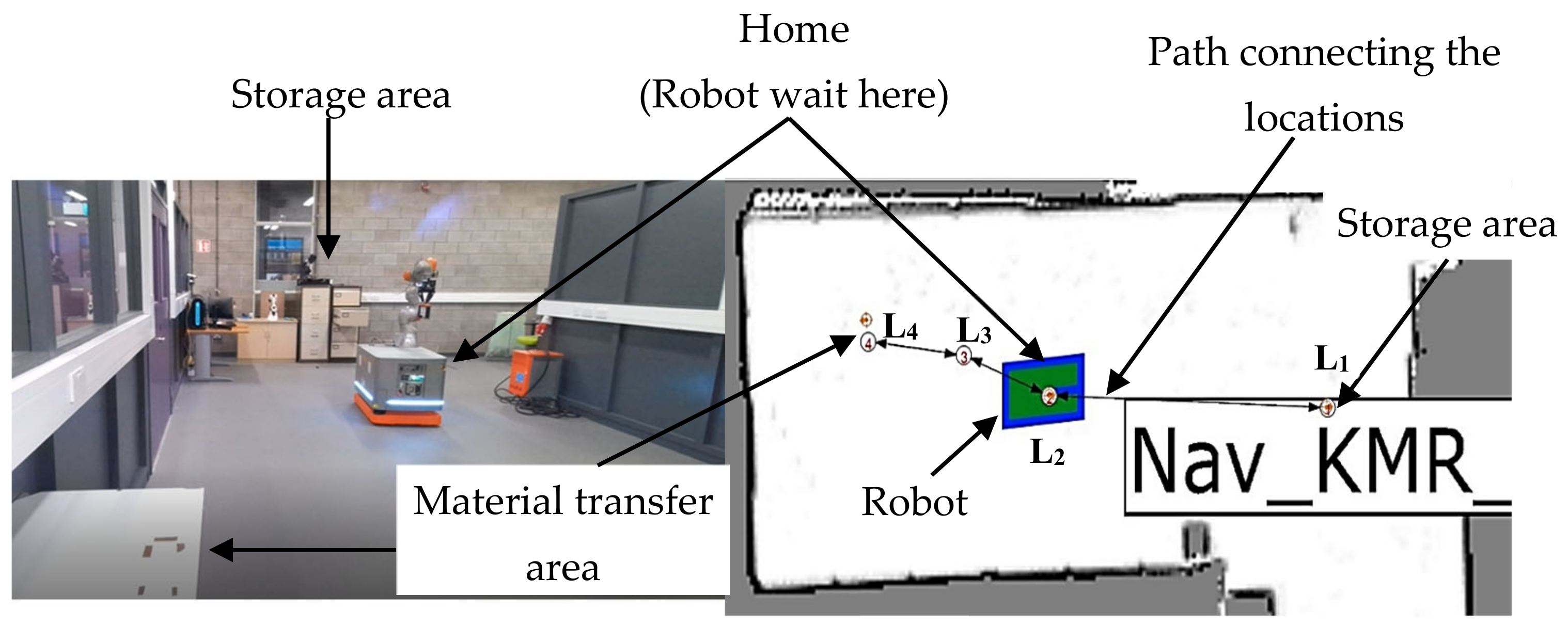
  • The mobile robot waits at its home location for the task to be assigned.
  • Once a task is assigned, the robot will move to the storage location. The robot uses the preprogrammed navigation algorithm and the map of the environment to plan the path, velocity etc. Here, the storage location is used to emulate the cryostorage area.
  • The mobile robot reaches the storage location, the arm is moved towards the storage unit, and the handle of the storage is grasped with the help of the gripper. Then the arm is moved back towards the robot to open the storage. Once the storage is opened, the robot will pick and raise the tray containing the centrifugal tubes. The robot then moves the arm back to a suitable configuration, so that the mobile robot can move without the arm clashing with any other objects nearby.
  • The mobile robot navigates to the material transfer area.
  • Upon reaching the material transfer area, the arm is moved towards the location where the tray must be placed. After reaching this location, the gripper releases the tray and the arm is retracted.
  • The robot navigates back to the home position, waiting for the next task.
Figure 3. Task flow diagram for the experiment using centrifugal tubes.
Applsci 12 10895 g003
Different steps during the execution of the task are shown in Figure 4. It shows the robot moving towards thestorage unit, opening the storage, picking the tray containing centrifuge tubes, moving to the material transfer area, and placing the tray in the assigned location.
The robot’s fine positioning feature is used in this experiment. During fine positioning, the platform offset is calculated using LiDAR data. The offset is then compensated by moving the platform towards the set point at a very low velocity. This operation is repeated for a set number of cycles (currently 5) or until the offset is below a set value (currently 10 mm). The accuracy is calculated by moving the robot to a fixed location and then measuring the offset after applying the fine positioning technique. The experiment is conducted 20 times and the average error is calculated.

3.3. Experiment 2: Manipulation of Deformable Fluid Bags

This experiment tests the potential of a mobile collaborative robot for manipulating deformable objects, specifically deformable infusion bags. Due to the risk of fluid spills if the bag were punctured, empty bags are used for the experiment instead of bags filled with fluid. An unfilled bag with a storage capacity of 500 mL and two ports is used for the experiment.
The mobile robotic platform is configured in the same manner as Experiment 1. The gripper attached to the robot allows changing the gripping force programaticaly through specific commands. The correct force for grasping is found using a trial and error approach, and depends on the mass of the bag being grasped, the frictional force between the bag and the grippers and the maximum acceleration of the robotic arm. The infusion bag is initially kept on a stand of height 650 mm. The experiment consists of the following steps:
  • The mobile robot waits at its home location.
  • Once the task is assigned, the robot moves to the bag collection area.
  • On reaching the bag collection area, the robot extends its arm toward the holder, which is kept towards the right side of the robot.
  • The robot collects the bag and places it on top of the robotic platform in the assigned location.
  • The robot moves back to the bag delivery location.
The top section of the bag is grasped by the robot, considering that tubes from the ports at the bottom of the bag will hinder proper grasping. However, other grasping orientations have also been tested. Figure 5 shows the robot handling the infusion bag. The bag is placed on a custom-made PLA platform, presented to the robot in such a manner that the robot can pick up the bag from the bottom side. The arm is then aligned with the bag to pick it up from the chosen side. The gripping force is controlled to hold the bag firmly enough without puncturing the bag. The bag is then raised from the bag holder and moved over the platform and the arm is reoriented to place the bag on a bag holder provided on the robot. The arm lowers the bag, and the gripper is slowly released to gently place the bag into the bag holder. Once the bag is placed securely, the arm is moved back and the mobile robot transports the bag to the location where it needs to be delivered.
Pick and place experiments are also performed with a fully sealed bag of fluid (non-frozen ice pack), to experiment with a filled bag while reducing the risk of damage from spillage.

3.4. Experiment 3: Manipulation of Petri Dishes for Scanning the QR Code

This experiment demonstrates the potential of a mobile collaborative robot for manipulating petri dishes to scan the QR code attached to the Petri dishes. A disposable 90 mm Petri dish is used for this study. A custom made PLA support structure attached to a stand of height 650 mm is used to position the dish for sampling. The vision system is used in this experiment to find the positioning error of the platform and for reading the QR code attached on the Petri dish. A task flow diagram for this experiment is shown in Figure 6. The experimental scenario consists of the following steps:
  • The robot waits at the home location for the task to be assigned.
  • The robot moves to the sampling location on receiving the scanning task. Information about the sampling location, such as location ID, stand height etc. is communicated to the robot.
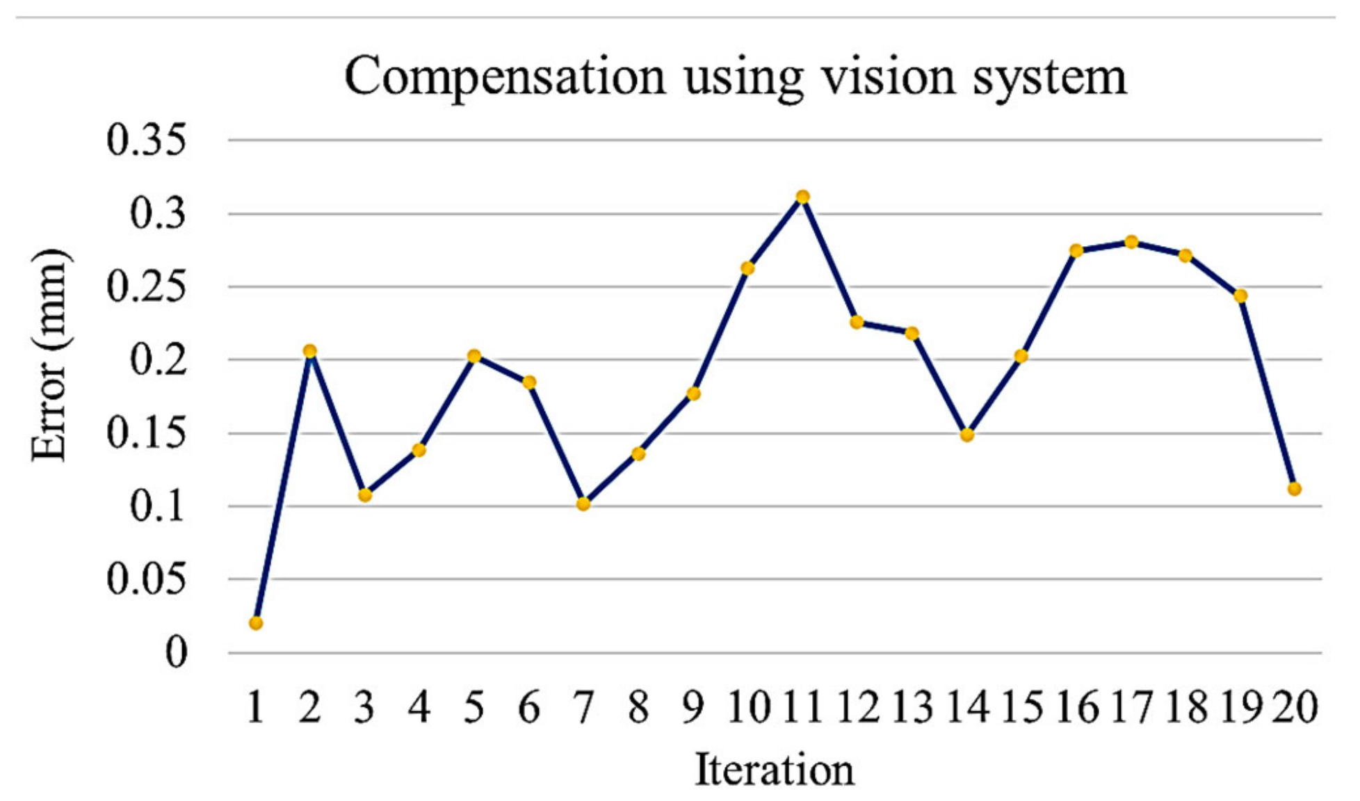
  • On reaching the sampling location, the robot extends the arm toward the sampling stand on top of which the dish and the lid is kept. An image of the stand is taken using the vision system to calculate the positioning error of the mobile platform. The positioning error of the platform in turn causes an error while picking the Petri dish. The robotic arm compensates for the platform error by providing the required additional motion corresponding to the error calculated using the vision system. The Petri dish is presented in an open condition with lid placed nearby on an assigned area.
  • The robot moves the arm to the pickup position with the gripper in open status. The robot closes the gripper to pick the lid up and place it on the dish.
  • The robot picks the Petri dish from the sampling stand, flips it, and places it back on the stand for scanning. The Petri dish is flipped so that the QR code placed at the bottom is visible. The robotic arm is then moved toward the scanning pose. The QR code is scanned using the camera attached to the robotic arm.
  • The robot picks up the Petri dish again and places it onto the carrying device kept on top of the robot. The information collected on scanning the dish is communicated to the LIMS system. The robot then waits for the next instructions.
Figure 6. Task flow diagram of the experiment using Petri dishes.
Applsci 12 10895 g006
Different steps of the experiment are shown in Figure 7. It is expected that very precise positioning is required in this experiment, therefore additional position compensation techniques are applied above the robot’s fine positioning feature described in Experiment 1. The error of the platform can be reduced using a predefined error compensation technique using the fine localisation capability of the robot. First, fine localisation allows the robot to localize itself using LiDAR data. From this information, the offset of the platform is measured, and this offset is then compensated by adjusting the motion of the arm.

4. Results and Discussion

4.1. Experiment 1: Manipulation and Transportation of Centrifugal Tubes

In the current work, the robot used was able to move the tray containing centrifugal tubes in 7 min and 14 s at 20% maximum speed. 20% was achieved only in places with no obstacles within 0.75 m around the robot. In other places, the velocity is limited to 10% to avoid reaching potential obstacles at a very short distance.
The robot was able to successfully complete the entire task and reach back to the home position by this time. The task cycle time can be reduced by running the robot at higher speeds, optimizing the motion, or avoiding delays during the manipulation. If the robot operates at its full speed, it can complete the task within 2 min. If the robot is operated continuously for a full day, allowing a total charging time of 4 h/day, the robot could perform this task 600 times/day. This is equivalent to relieving 2.5 humans from the mundane task of moving these tubes. The overall cost of a robot like the one used in the current work is around 200,000 euros. Considering that an average salary of an employee in the biomanufacturing sector is 40,000 euros, a reasonable break-even period can be expected with an added advantage of a reduction in contamination and human errors. Similarly, at a maximum velocity of 25%, the robot took <3 min to pick the Petri dish up and scan the QR code. This task could be completed in less than 1 min if the robot is operated at its full speed. Allowing for travel time between sampling points still corresponds to several hundred tasks/day, considering that the robot is charging for 4 h/day.
Although the robot can use the vision system to correct the error, this functionality was not used in this experiment as the robot was able to complete the task successfully by applying the fine positioning technique. The average accuracy of the fine positioning technique was found to be 10.2 mm, which is adequate for this task; results are shown in Figure 8.
The experiment shows the ability of the robot to complete such material transfer tasks in a human-like manner. The robot can therefore replace a human operator without modifying much of the current hardware and equipment in a typical biomanufacturing facility. Figure 9 shows the robot reaching inside the storage to grasp the rack. The figure shows the dexterity capabilities of the robot to reach inside the storage to collect objects. The three-finger gripper allows the tray to be grasped in a configuration similar to how a human would do the same task.
These robots are also capable of updating their live location on the map. Figure 10 shows the location of the robot being updated on the map as it moves toward the storage area. This data can be used for motion planning when more than one robot operates in the facility. The map can also be used by a human operator residing in a remote room to monitor the robot. Overall, this data can be used for monitoring the biomanufacturing facility.

4.2. Experiment 2: Manipulation of Deformable Fluid Bags

The automation of the task of transferring infusion bags as in Experiment 2 will reduce the possibility of contamination as well as the variability in production. However, modification of the cabling, robot body, gripper, etc. is necessary to comply with GMP. The robot and the attached peripherals cannot be easily sanitised in their current form, and a lot of parts of the robot provide space for collecting dust and microbes. However, low particle emission collaborative robots that suit cleanroom requirements are available on the market [102].
Gripping from the top, where, the robot grasps the bag from the top side where ports are not present, seemed to be the most successful method for manipulating sealed bags. For a filled and sealed bag, the structure at the inlet allows the robot to grasp the bag firmly, whereas in the case of the unfilled infusion bags shown in Figure 5, tubes at the inlet portion will hinder the grasping. Filled bags can also be grasped from the side where ports are not there, provided fluid will not flow out through the ports. However, this is not an ideal point as the bag can slip if not held firmly. Similarly, the robot, with the help of the 3-finger adaptive gripper could hold the bag just like humans do. This is possible only if the bag is appropriate for grasping and not too large. There is also a possibility of the bag being punctured if it is trapped between the joints of the gripper finger.

4.3. Experiment 3: Manipulation of Petri Dishes for Scanning the QR Code

The robot successfully demonstrated the ability to manipulate the Petri dish to complete the task. One important consideration is the positional accuracy of each component of the mobile robot.
The average positioning error of the mobile robotic platform used in this work was found to be 10.2 mm without applying any error correction but by using the fine positioning technique as explained in experiment 1. This error was acceptable in Experiment 1 but is not suitable for the precise manipulation of Petri dishes. The average error after using the more advanced error compensation technique was found to be 1.9 mm and the maximum error exceeded 3 mm as shown in Figure 11. This is a significant improvement but still not good enough. Solving this error is critical for successfully executing tasks, such as placing the lid on the Petri dish after environmental sampling.
The maximum error of the platform should be less than 1.5 mm for the correct dish placement which corresponds to the average gap between the lid and the dish. One way of solving this problem is by using advanced sensors, such as a vision system to find the error. The robotic arm mounted on the mobile platform can then use the information about the platform error calculated by the vision system and compensate for this error. In the current work, the error compensation technique using the vision system was able to reduce the average error to 0.19 mm with a maximum error <0.5 mm as shown in Figure 12. Hence, it is concluded that a vision system is essential for this task.

4.4. General Discussion

Numerous biomanufacturing tasks can be automated with the help of a robot. Several specialised types of stationary robots have been developed for carrying out special bioprocessing tasks, such as pipetting, shaking, and analysing samples. The combined use of these special robots with standard industrial collaborative mobile platforms, if proven to be reliable over a long period, could increase the degree of automation in biomanufacturing. The downstream packaging process is already partly automated, but this could become fully automated with suitable robots. A series of tasks involving material storage and restocking, material transport, and facility cleaning and sanitisation could also be automated.
Although there is huge potential for mobile robots in the biomanufacturing sector, some key issues must be addressed. One such issue is related to the positional accuracy of the platform; a mobile robotic platform is comparatively less accurate than a fixed robotic manipulator. As shown in this paper, the robot’s in-built features are acceptable for some tasks, but when precision up to millimetre order is required, it is necessary to add additional sensors, such as the vision system used here.
The safety of the operator and other equipment also needs to be considered while deploying robotic platforms in biomanufacturing facilities. The mobile robotic system safety is heavily dependent on the program that controls the system. In human-robot collaborative scenarios, there is a trade-off between the robot velocity and safety [103]. Hence operating the robot at its full speed is not ideal from a safety point of view. The tasks demonstrated in this work involve the robot operating without any direct interaction with human operators., but it is also possible to sequence the routine tasks in such a manner that the robot will do one task and the human will do an adjacent task. For example, the robot can be used to transport the sampled dishes to the laboratory for testing while the operator carries out the tests. In this co-existence scenario, there will be little direct physical interaction between the robot and the human, minimising the safety risk for operators but still requiring robots to function very reliably.
This can be challenging due to the complexity of the process. A typical biomanufacturing facility is very dynamic; the production layout can change from time to time due to the introduction of new equipment and bioreactors, and much of the equipment may be mobile, without precisely fixed positions. There should be adequate measures to ensure that the robot will adapt to these changes. For example, if there are moveable obstacles or operators present in the path selected by the robot, the robot should be able to select alternate routes. In many cases, there will be narrow corridors in biomanufacturing facilities. The tighter clearance will reduce the robot’s ability to traverse at its highest possible speed, thereby increasing the time required to complete the assigned task. All these challenges suggest the use of advanced collaborative mobile robots, such as the one in this study, over more traditional robots.
The manipulation of deformable bags in Experiment 2 is another example of variability that the robot has to overcome. Traditional manufacturing applications of robotics typically use fixtures rigidly designed for a specific task, however, the 3-finger gripper used here has demonstrated the flexibility to carry out several different tasks, including the manipulation of deformable bags without a fixed shape. The use of force-sensitive adaptive grippers along with the 3-D vision system, and potentially other sensors, will be best suited to make the robotic platform adaptable to varying conditions.

5. Conclusions

The potential for introducing mobile collaborative robotic platforms in the biomanufacturing sector in general, and in the personalised therapeutic sector in particular, was investigated in this paper. The applications that were primarily identified are related to the transportation and handling of equipment and devices as well as environmental sampling and monitoring. Automating these tasks will lead to lower contamination risks, manufacturing costs, and product prices, considering that labour costs account for up to 30% of production costs [104], while allowing microbiologists and operators to carry out more complex operations or to focus on process design and optimisation tasks.
A collaborative mobile robot was used to carry out a series of different tasks, such as manipulation and transport of centrifugal tubes, manipulation of deformable medical fluid bags and manipulation of Petri dishes for scanning the QR code. The robotic platform was able to complete all these tasks successfully.
Applications, such as the ones discussed in this paper will need to be validated through more testing. These tests can be carried out initially in biomanufacturing research facilities like the National Institute for Bioprocessing Research and Training (NIBRT) [105]. These tests will involve using the mobile robot to transport and manipulate the actual equipment used for production and verify the success rate, task completion time and contamination reduction. The solution can then be further tested in an actual production plant for final validation.
The bioprocessing industry is at a crossroads where the level of automation adoption could shape the industry’s future. For this to become a reality, a series of challenges related to the programming, commissioning and operation of robots will have to be overcome. Robots should be capable of exhibiting flexibility and versatility in a very conservative, risk-averse industry, and it will have to be demonstrated that they may indeed increase product safety and production throughput in a cost-effective manner. More flexible automation may lead to faster, cost-efficient personalisation of biomanufacturing products.

Author Contributions

Conceptualisation, N.P. and R.M. (Robins Mathew); methodology, R.M. (Robins Mathew) and R.M. (Robert McGee); software, R.M. (Robins Mathew); validation, R.M. (Robins Mathew) and R.M. (Robert McGee); writing—original draft preparation, R.M. (Robins Mathew) and R.M. (Robert McGee).; writing—review and editing R.M. (Robins Mathew), K.R., S.W. and N.P.; visualisation, R.M. (Robins Mathew) and R.M. (Robert McGee); supervision, N.P.; project administration, N.P.; funding acquisition, N.P. All authors have read and agreed to the published version of the manuscript.

Funding

This work was supported by Enterprise Ireland funded project MARVIN under project grant IP/2017/0671/A, co-funded by the Irish Government and the European Union, as well as by PM Group Limited, Lonza Walkersville Inc. and Novartis Pharma AG.

Institutional Review Board Statement

Not applicable.

Informed Consent Statement

Not applicable.

Data Availability Statement

Not applicable.

Acknowledgments

We would like to thank the National Institute for Bioprocessing Research & Training for helping us conduct this study and for arranging discussions with experts from the biomanufacturing sector. We thank Abraham George from University College Dublin for helping us to design and prototype the equipment used in this work.

Conflicts of Interest

The authors declare no conflict of interest.

References

  1. Schuster, S. COBOTS in Cleanrooms—The New Dimension of Automated Semiconductor Production; KUKA Deutschland GmbH: Augsburg, Germany, 2021. [Google Scholar]
  2. Sandle, T. People in Cleanrooms: Understanding and Monitoring the Personnel Factor. Available online: https://www.ivtnetwork.com/article/people-cleanrooms-understanding-and-monitoring-personnel-factor (accessed on 16 November 2021).
  3. Sandle, T. The people factor: Investigating the gown. Eur. Pharm. Rev. 2017, 22, 23–26. [Google Scholar]
  4. Hyde, W.A. Origin of bacteria in the clean room and their growth requirements. PDA J. Pharm. Sci. Technol. 1998, 52, 154–158. [Google Scholar]
  5. Beri, R.G.; Wolton, D.; Coulon, C.-H. Opportunities for Modern Robotics in Biologics Manufacturing. Bioprocess Int. 2019, 17, 8–15. [Google Scholar]
  6. Miller, S.; Zakharyevich, K.; Kavanaugh, D.; Lenich, R.; Salim, J.; Iles-Smith, P.; Schelble, C.; Sheehy, P.; Merkle, S.; Beri, R. Biomanufacturing Technology Roadmap: 4. Automated Facilities; BioPhorum Operations Group, Ltd.: London, UK, 2017; p. 34. [Google Scholar]
  7. Stanton, D. The 4 Degrees of Automation in Cell Therapy Manufacture. Available online: https://bioprocessintl.com/bioprocess-insider/therapeutic-class/the-4-degrees-of-automation-in-cell-therapy-manufacture/?utm_medium=email&_hsmi=206184161&_hsenc=p2ANqtz-_26kfRxjy7VRDuc6uWRAcpaCQVkUqNZSsHBjPTBTftQxSo5WhBqNvBgBqo587pLd7WvCek1B0L6Wcy3W9Tmhxm (accessed on 13 March 2022).
  8. Burger, B.; Maffettone, P.M.; Gusev, V.V.; Aitchison, C.M.; Bai, Y.; Wang, X.; Li, X.; Alston, B.M.; Li, B.; Clowes, R.; et al. A mobile robotic chemist. Nature 2020, 583, 237–241. [Google Scholar] [CrossRef]
  9. Hardner, M.; Schneider, D. Development of a multi camera calibration for an analysis and manipulation system of biological samples in petri dishes. ISPRS—Int. Arch. Photogramm. Remote Sens. Spat. Inf. Sci. 2019, XLII-2/W18, 67–72. [Google Scholar] [CrossRef] [Green Version]
  10. Lange, O.; Erhard, M.; Teutsch, C.; Sander, J. MIROB: Automatic rapid identification of micro-organisms in high through-put. Ind. Robot Int. J. 2008, 35, 311–315. [Google Scholar] [CrossRef]
  11. Sabatini, L.; Paolucci, D.; Marinelli, F.; Pianetti, A.; Sbaffo, M.; Bufarini, C.; Sisti, M. Microbiological validation of a robot for the sterile compounding of injectable non-hazardous medications in a hospital environment. Eur. J. Hosp. Pharm. 2019, 27, 63–86. [Google Scholar] [CrossRef] [Green Version]
  12. Takalo-Kippola, H.; Lappalainen, P. Novel laboratory robot for the manufacturing of microbiological culture media. In Proceedings of the 16th Annual International Conference of the IEEE Engineering in Medicine and Biology Society, Baltimore, MD, USA, 3–6 November 1994; Volume 16, pp. 1055–1056. [Google Scholar] [CrossRef]
  13. U.S Food and Drug Administration. Personalized Medicine: A Biological Approach to Patient Treatment. Available online: https://www.fda.gov/drugs/news-events-human-drugs/personalized-medicine-biological-approach-patient-treatment (accessed on 3 June 2022).
  14. Kumar, K.; Kon, O.M. Personalised medicine for tuberculosis and non-tuberculous mycobacterial pulmonary disease. Microorganisms 2021, 9, 2220. [Google Scholar] [CrossRef]
  15. Pritchard, D.E.; Moeckel, F.; Villa, M.S.; Housman, L.T.; McCarty, C.A.; McLeod, H.L. Strategies for integrating personalized medicine into healthcare practice. Pers. Med. 2017, 14, 141–152. [Google Scholar] [CrossRef] [Green Version]
  16. Horgan, D. Access for All: A Personalised Approach. Public Health Genom. 2016, 19, 129–131. [Google Scholar] [CrossRef]
  17. Golubnitschaja, O.; Baban, B.; Boniolo, G.; Wang, W.; Bubnov, R.; Kapalla, M.; Krapfenbauer, K.; Mozaffari, M.S.; Costigliola, V. Medicine in the early twenty-first century: Paradigm and anticipation—EPMA position paper 2016. EPMA J. 2016, 7, 23. [Google Scholar] [CrossRef] [Green Version]
  18. Dos Santos, F.F.; Andrade, P.Z.; Da Silva, C.L.; Cabral, J.M.S. Bioreactor design for clinical-grade expansion of stem cells. Biotechnol. J. 2013, 8, 644–654. [Google Scholar] [CrossRef]
  19. Eaker, S.; Armant, M.; Brandwein, H.; Burger, S.; Campbell, A.; Carpenito, C.; Clarke, D.; Fong, T.; Karnieli, O.; Niss, K.; et al. Concise review: Guidance in developing commercializable autologous/patient-specific cell therapy manufacturing. Stem Cells Transl. Med. 2013, 2, 871–883. [Google Scholar] [CrossRef]
  20. Wang, K.; Liu, Y.; Li, J.; Wang, B.; Bishop, R.; White, C.; Das, A.; Levine, A.D.; Ho, L.; Levine, B.L.; et al. A multiscale simulation framework for the manufacturing facility and supply chain of autologous cell therapies. Cytotherapy 2019, 21, 1081–1093. [Google Scholar] [CrossRef] [PubMed]
  21. Lexchin, J. Affordable biologics for all. JAMA Netw. Open 2020, 3, e204753. [Google Scholar] [CrossRef]
  22. Marks, P.; Witten, C. Toward a new framework for the development of individualized therapies. Gene Ther. 2020, 28, 615–617. [Google Scholar] [CrossRef] [Green Version]
  23. Löfving, M.; Almström, P.; Jarebrant, C.; Wadman, B.; Widfeldt, M. Evaluation of flexible automation for small batch production. Procedia Manuf. 2018, 25, 177–184. [Google Scholar] [CrossRef]
  24. Hamburg, M.A.; Collins, F.S. The path to personalized medicine. N. Engl. J. Med. 2010, 363, 301–304. [Google Scholar] [CrossRef]
  25. Miossec, P.; Verweij, C.L.; Klareskog, L.; Pitzalis, C.; Barton, A.; Lekkerkerker, F.; Reiter, S.; Laslop, A.; Breedveld, F.; Abadie, E.; et al. Biomarkers and personalised medicine in rheumatoid arthritis: A proposal for interactions between academia, industry and regulatory bodies. Ann. Rheum. Dis. 2011, 70, 1713–1718. [Google Scholar] [CrossRef]
  26. Meybodi, H.R.A.; Hasanzad, M.; Larijani, B. Path to personalized medicine for type 2 diabetes mellitus: Reality and hope. Acta Med. Iran. 2017, 55, 166–174. [Google Scholar]
  27. Mishra, V.; Chanda, P.; Tambuwala, M.M.; Suttee, A. Personalized medicine: An overview. Int. J. Pharm. Qual. Assur. 2019, 10, 290–294. [Google Scholar] [CrossRef]
  28. Malik, N. Allogeneic versus Autologous Stem-Cell Therapy. BioPharm Int. 2012, 25, 18–22. [Google Scholar]
  29. Precision Medicines: Adapting Manufacturing for Small Batch. Available online: https://www.theaccessgroup.com/en-gb/manufacturing/resources/pharma-insights/precision-medicines-adapting-manufacturing-for-the-super-small-batch/ (accessed on 3 June 2022).
  30. Vormittag, P.; Gunn, R.; Ghorashian, S.; Veraitch, F.S. A guide to manufacturing CAR T cell therapies. Curr. Opin. Biotechnol. 2018, 53, 164–181. [Google Scholar] [CrossRef]
  31. Bartel, R.L. Stem Cells and Cell Therapy: Autologous Cell Manufacturing. In Translational Regenerative Medicine; Academic Press: Cambridge, MA, USA, 2015; pp. 107–112. [Google Scholar] [CrossRef]
  32. Abraham, E.; Ahmadian, B.B.; Holderness, K.; Levinson, Y.; McAfee, E. Platforms for manufacturing allogeneic, autologous and iPSC cell therapy products: An industry perspective. Adv. Biochem. Eng. Biotechnol. 2018, 165, 323–350. [Google Scholar]
  33. Pigeau, G.M.; Csaszar, E.; Dulgar-Tulloch, A. Commercial scale manufacturing of allogeneic cell therapy. Front. Med. 2018, 5, 233. [Google Scholar] [CrossRef]
  34. Schubert, H. The Challenges of Personalized Drugs—And Some Possible Solutions. Tech Talk. Available online: https://www.nne.com/techtalk/how-personalized-drugs-are-changing-pharma-manufacturing/ (accessed on 3 March 2022).
  35. Veronesi, E.; Murgia, A.; Caselli, A.; Grisendi, G.; Piccinno, M.S.; Rasini, V.; Giordano, R.; Montemurro, T.; Bourin, P.; Sensebé, L.; et al. Transportation conditions for prompt use of ex vivo expanded and freshly harvested clinical-grade bone marrow mesenchymal stromal/stem cells for bone regeneration. Tissue Eng.—Part C Methods 2014, 20, 239–251. [Google Scholar] [CrossRef] [Green Version]
  36. Hanna, J.; Hubel, A. Preservation of stem cells. Organogenesis 2009, 5, 134–137. [Google Scholar] [CrossRef] [Green Version]
  37. Celikkan, F.T.; Mungan, C.; Sucu, M.; Ulus, A.T.; Cinar, O.; Ili, E.G.; Can, A.L.P. Optimizing the transport and storage conditions of current Good Manufacturing Practice –grade human umbilical cord mesenchymal stromal cells for transplantation (HUC-HEART Trial). Cytotherapy 2019, 21, 64–75. [Google Scholar] [CrossRef]
  38. Aghayan, H.R.; Arjmand, B.; Ahmadbeigi, N.; Gheisaii, Y.; Vasei, M. Draft of Iranian national guideline for cell therapy manufacturing. Arch. Iran. Med. 2017, 20, 547–550. [Google Scholar]
  39. Rotondi, M.; Grace, N.; Betts, J.; Bargh, N.; Costariol, E.; Zoro, B.; Hewitt, C.J.; Nienow, A.W.; Rafiq, Q.A. Design and development of a new ambr250Ò bioreactor vessel for improved cell and gene therapy applications. Biotechnol. Lett. 2021, 43, 1103–1116. [Google Scholar] [CrossRef]
  40. Cabrita, G.J.M.; Ferreira, B.S.; Lobato Da Silva, C.; Gonçalves, R.; Almeida-Porada, G.; Cabral, J.M.S. Hematopoietic stem cells: From the bone to the bioreactor. Trends Biotechnol. 2003, 21, 233–240. [Google Scholar] [CrossRef]
  41. Ling, Y.; Ae, N.; Chase, H.A. Novel bioreactors for the culture and expansion of aggregative neural stem cells. Bioprocess Biosyst. Eng. 2008, 31, 393–400. [Google Scholar] [CrossRef]
  42. Sardonini, C.A.; Wu, Y.-J. Expansion and Differentiation of Human Hematopoietic Cells from Static Cultures through Small-Scale Bioreactors. Biotechnol. Prog. 1993, 9, 131–137. [Google Scholar] [CrossRef]
  43. Palsson, B.O.; Paek, S.-H.; Schwartz, R.M.; Palsson, M.; Lee, G.-M.; Silver, S.; Emerson, S.G. Expansion of human bone marrow progenitor cells in a high cell density continuous perfusion system. BioTechnology 1993, 11, 368–372. [Google Scholar] [CrossRef]
  44. Meissner, P.; Schröder, B.; Herfurth, C.; Biselli, M. Development of a fixed bed bioreactor for the expansion of human hematopoietic progenitor cells. Cytotechnology 1999, 30, 227–234. [Google Scholar] [CrossRef]
  45. Yao, C.L.; Liu, C.H.; Chu, I.M.; Hsieh, T.B.; Hwang, S.M. Factorial designs combined with the steepest ascent method to optimize serum-free media for ex vivo expansion of human hematopoietic progenitor cells. Enzyme Microb. Technol. 2003, 33, 343–352. [Google Scholar] [CrossRef]
  46. Weber, C.; Pohl, S.; Poertner, R.; Wallrapp, C.; Geigle, P.; Czermak, P. Development of a production process for stem cell based cell therapeutic implants using disposable bioreactor systems. IFMBE Proc. 2008, 22, 2277–2280. [Google Scholar]
  47. Nienow, A.W.; Coopman, K.; Heathman, T.R.J.; Rafiq, Q.A.; Hewitt, C.J. Bioreactor Engineering Fundamentals for Stem Cell Manufacturing; Elsevier: Amsterdam, The Netherlands, 2016; ISBN 9780444632654. [Google Scholar]
  48. Nogueira, D.E.S.; Rodrigues, C.A.V.; Carvalho, M.S.; Miranda, C.C.; Hashimura, Y.; Jung, S.; Lee, B.; Cabral, J.M.S. Strategies for the expansion of human induced pluripotent stem cells as aggregates in single-use Vertical-Wheel™ bioreactors. J. Biol. Eng. 2019, 13, 74. [Google Scholar] [CrossRef] [Green Version]
  49. ISO 14644-1:1999(en); Cleanrooms and Associated Controlled Environments—Part 1: Classification of Air Cleanliness. International Organization for Standardization: Geneva, Switzerland, 1999. Available online: https://www.iso.org/obp/ui/#iso:std:iso:14644:-1:ed-1:v1:en (accessed on 16 November 2021).
  50. Niazi, S.K. Handbook of Pharmaceutical Manufacturing Formulations, 3rd ed.; Compressed Solid Products; CRC Press: Boca Raton, FL, USA, 2019; Volume 1, ISBN 9781420081176. [Google Scholar]
  51. Tim Sandle Best Practices In Environmental Monitoring [White Paper]. Reading Scientific Services Ltd. 2020. Available online: https://www.researchgate.net/publication/342883006_Best_practices_in_environmental_monitoring (accessed on 7 July 2022).
  52. Kuehn, S. Ascent of the Robots—Advancing Aseptic Proccessing through the Use of Robot Technology. Available online: https://www.pharmamanufacturing.com/articles/2015/ascent-of-the-robots/ (accessed on 9 March 2022).
  53. Kokubo, M.; Akers, J.E. Aseptic Manufacturing of Regenerative Medicine Products Using Isolator Technology; Springer: Tokyo, Japan, 2016; ISBN 9784431556664. [Google Scholar]
  54. Bruscolini, F.; Paolucci, D.; Rosini, V.; Sabatini, L.; Andreozzi, E.; Pianetti, A. Evaluation of ultraviolet irradiation efficacy in an automated system for the aseptic compounding using challenge test. Int. J. Qual. Health Care 2015, 27, 412–417. [Google Scholar] [CrossRef] [Green Version]
  55. Yi, J.; Zhang, H.; Zhao, C.; Che, A.; Wang, Y. Key technologies and progress of pharmaceutical intelligent manufacturing production line. J. Cent. South Univ. Sci. Technol. 2021, 52, 421–433. [Google Scholar] [CrossRef]
  56. Krämer, I.; Federici, M.; Kaiser, V.; Thiesen, J. Media-fill simulation tests in manual and robotic aseptic preparation of injection solutions in syringes. J. Oncol. Pharm. Pract. 2016, 22, 195–204. [Google Scholar] [CrossRef]
  57. Hafner, J. Spool production goes aseptic. Cleanroom Technol. 2008, 15, 13–15. [Google Scholar]
  58. Geersing, T.H.; Franssen, E.J.F.; Pilesi, F.; Crul, M. Microbiological performance of a robotic system for aseptic compounding of cytostatic drugs. Eur. J. Pharm. Sci. 2019, 130, 181–185. [Google Scholar] [CrossRef]
  59. Keller, M.; Baum, G.; Schweizer, M.; Bürger, F.; Gommel, U.; Bauernhansl, T. Optimized Robot Systems for Future Aseptic Personalized Mass Production. Procedia CIRP 2018, 72, 303–309. [Google Scholar] [CrossRef]
  60. Alip, S.L.; Kim, J.; Rha, K.H.; Han, W.K. Future Platforms of Robotic Surgery. Urol. Clin. N. Am. 2022, 49, 23–38. [Google Scholar] [CrossRef]
  61. Khandalavala, K.; Shimon, T.; Flores, L.; Armijo, P.R.; Oleynikov, D. Emerging surgical robotic technology: A progression toward microbots. Ann. Laparosc. Endosc. Surg. 2020, 5, 3. [Google Scholar] [CrossRef]
  62. Nota, C.L.M.A.; Smits, F.J.; Woo, Y.; Borel Rinkes, I.H.M.; Molenaar, I.Q.; Hagendoorn, J.; Fong, Y. Robotic Developments in Cancer Surgery. Surg. Oncol. Clin. N. Am. 2019, 28, 89–100. [Google Scholar] [CrossRef]
  63. Kim, Y.J. The future medical science and colorectal surgeons. Ann. Coloproctol. 2017, 33, 207–209. [Google Scholar] [CrossRef] [Green Version]
  64. Jeon, H.; Yang, K.-M.; Park, S.; Choi, J.; Lim, Y. An Ontology-based Home Care Service Robot for Persons with Dementia. In Proceedings of the RO-MAN 2018—27th IEEE International Symposium on Robot and Human Interactive Communication, Nanjing, China, 27–31 August 2018; pp. 540–545. [Google Scholar]
  65. Salemi, B.; Reis, J.; Saifhashemi, A.; Nikgohar, F. MILO: Personal robot platform. In Proceedings of the 2005 IEEE/RSJ International Conference on Intelligent Robots and Systems, IROS, Edmonton, AB, Canada, 2–6 August 2005; pp. 4089–4094. [Google Scholar]
  66. Yang, G.; Wang, S. Modeling and Control of a Personal Care Robot Considering Posture Adjustment. In Proceedings of the 2019 IEEE International Conference on Mechatronics and Automation, ICMA 2019, Tianjin, China, 4–7 August 2019; pp. 1414–1418. [Google Scholar]
  67. Kataria, S.; Ravindran, V. Digital health: A new dimension in rheumatology patient care. Rheumatol. Int. 2018, 38, 1949–1957. [Google Scholar] [CrossRef]
  68. Baimas-George, M.; Demartines, N.; Vrochides, D. The role of disruptive technologies and approaches in ERAS®: Erupting change through disruptive means. Langenbecks Arch. Surg. 2022, 407, 437–441. [Google Scholar] [CrossRef]
  69. Palm, E.; Nordgren, A.; Verweij, M.; Collste, G. Ethically sound technology? Guidelines for interactive ethical assessment of personal health monitoring. Stud. Health Technol. Inform. 2013, 187, 105–114. [Google Scholar] [CrossRef]
  70. Virk, G.S. Personal care robot safety. In Proceedings of the Emerging Trends in Mobile Robotics, 13th International Conference on Climbing and Walking Robots and the Support Technologies for Mobile Machines, CLAWAR 2010, Singapore, 31 August–3 September 2010; pp. 1332–1339. [Google Scholar]
  71. Villaronga, E.F.; Virk, G.S. Legal Issues for Mobile Servant Robots; Springer: Cham, Switzerland, 2017; Volume 540, ISBN 9783319490571. [Google Scholar]
  72. Kochan, A. Cleanroom robots become cleaner and more reliable. Ind. Robot 1998, 25, 27–29. [Google Scholar] [CrossRef]
  73. Kuehn, T.H.; Wu, Y.; Liu, B.Y.H. Particle contamination below a robot arm in a cleanroom. J. IES 1993, 36, 43–50. [Google Scholar] [CrossRef]
  74. Mathia, K. Robot design for wafer handling. Cleanroom Technol. 2010, 18, 22–23. [Google Scholar]
  75. Ma, R.-H. Study on simulation of airflow within the enclosure in the semiconductor factory cleanroom. Aerosol Sci. Technol. 2006, 40, 282–292. [Google Scholar] [CrossRef] [Green Version]
  76. Wolton, D. An Autonomous Sampling System. U.S. Patent 16/333,765, 11 July 2019. [Google Scholar]
  77. Wolf, Á.; Wolton, D.; Trapl, J.; Janda, J.; Romeder-Finger, S.; Gatternig, T.; Farcet, J.B.; Galambos, P.; Széll, K. Towards robotic laboratory automation Plug & Play: The “LAPP” framework. SLAS Technol. 2022, 27, 18–25. [Google Scholar] [CrossRef]
  78. Bejczy, B.; Bozyil, R.; Vaiekauskas, E.; Petersen, S.B.K.; Bogh, S.; Hjorth, S.S.; Hansen, E.B. Mixed reality interface for improving mobile manipulator teleoperation in contamination critical applications. Procedia Manuf. 2020, 51, 620–626. [Google Scholar] [CrossRef]
  79. EI Marvin—Robotic Automation in the Biotechnology Sector—UCD Laboratory for Advanced Manufacturing Simulation and Robotics. Available online: https://www.ucd.ie/lams/research/projects/marvin/ (accessed on 17 July 2022).
  80. Froelich, K.; Pueschel, R.C.; Birner, M.; Kindermann, J.; Hackenberg, S.; Kleinsasser, N.H.; Hagen, R.; Staudenmaier, R. Optimization of fibrinogen isolation for manufacturing autologous fibrin glue for use as scaffold in tissue engineering. Artif. Cells Blood Substit. Biotechnol. 2010, 38, 143–149. [Google Scholar] [CrossRef]
  81. Cell Separation and Cell Isolation: Techniques, Methods, Applications. Available online: https://www.stemcell.com/cell-separation (accessed on 7 March 2022).
  82. Himac Practical Applications of Biological Centrifugation. Available online: https://www.himac-science.com/casebook/bio/bio-casebook.pdf (accessed on 7 March 2022).
  83. Schmolz, M.; Stein, G.M.; Hubner, W.-D. An innovative, centrifugation-free method to prepare human platelet mediator concentrates showing activities comparable to platelet-rich plasma. Wounds 2011, 23, 171–182. [Google Scholar]
  84. Levinson, Y.; Beri, R.G.; Holderness, K.; Ben-Nun, I.F.; Shi, Y.; Abraham, E. Bespoke cell therapy manufacturing platforms. Biochem. Eng. J. 2018, 132, 262–269. [Google Scholar] [CrossRef]
  85. Xu, Y.; Zhang, X.J.; Fang, L.; Zhao, T.B. Co-culture of annulus fbrosus cells and bone marrow mesenchymal stem cells. Genet. Mol. Res. 2015, 14, 3932–3938. [Google Scholar] [CrossRef]
  86. Applikon miniBio—Small Size Multi-Use Glass Autoclavable Bioreactor. Available online: https://www.getinge.com/int/products/applikon-minibio/ (accessed on 8 June 2022).
  87. Global Market Insights Inc. Medical Fluid Bags Market. Available online: https://www.gminsights.com/industry-analysis/medical-fluid-bags-market (accessed on 10 March 2022).
  88. LyondellBasell. Infusion Bags. Available online: https://www.lyondellbasell.com/en/products-technology/polymers/application/infusion-bags/ (accessed on 10 March 2022).
  89. Hermosilla, J.; Pérez-Robles, R.; Salmerón-García, A.; Casares, S.; Cabeza, J.; Navas, N. Stability study over time of clinical solutions of ziv-aflibercept prepared in infusion bags using a proper combination of physicochemical and functional strategies. J. Pharm. Biomed. Anal. 2021, 203, 114209. [Google Scholar] [CrossRef]
  90. Illum, L.; Bundgaard, H. Sorption of drugs by plastic infusion bags. Int. J. Pharm. 1982, 10, 339–351. [Google Scholar] [CrossRef]
  91. Leuenberger, N.; Barras, L.; Nicoli, R.; Robinson, N.; Baume, N.; Lion, N.; Barelli, S.; Tissot, J.D.; Saugy, M. Urinary di-(2-ethylhexyl) phthalate metabolites for detecting transfusion of autologous blood stored in plasticizer-free bags. Transfusion 2016, 56, 571–578. [Google Scholar] [CrossRef]
  92. Marinelli Busilacchi, E.; Costantini, A.; Mancini, G.; Bencivenga, R.; Olivieri, J.; Battaglini, G.; Velletri, L.; Viola, N.; Butini, L.; Capelli, D.; et al. A novel method to evaluate prethawing viability of cryopreserved CD34+ hematopoietic stem cells for autologous transplantation. Transfusion 2020, 60, 1529–1535. [Google Scholar] [CrossRef]
  93. Woods, E.J.; Thirumala, S. Packaging considerations for biopreservation. Transfus. Med. Hemother. 2011, 38, 149–156. [Google Scholar] [CrossRef] [Green Version]
  94. Mikola, M.; Seto, J.; Amanullah, A. Evaluation of a novel Wave Bioreactor® cellbag for aerobic yeast cultivation. Bioprocess Biosyst. Eng. 2007, 30, 231–241. [Google Scholar] [CrossRef]
  95. Kadwell, S.H.; Overton, L.K. Protein expression in insect and mammalian cells using baculoviruses in wave bioreactors. In Baculovirus and Insect Cell Expression Protocols; Humana Press: New York, NY, USA, 2016; Volume 1350. [Google Scholar]
  96. Da Silva, J.S.; Mizukami, A.; Gil, L.V.G.; de Campos, J.V.; Assis, O.B.; Tadeu Covas, D.; Swiech, K.; Torres Suazo, C.A. Improving wave-induced motion bioreactor performance for human mesenchymal stromal cell expansion. Process Biochem. 2019, 84, 143–152. [Google Scholar] [CrossRef]
  97. Tsai, A.-C.; Pacak, C.A. Bioprocessing of human mesenchymal stem cells: From planar culture to microcarrier-based bioreactors. Bioengineering 2021, 8, 96. [Google Scholar] [CrossRef]
  98. Whyte, W. In support of settle plates. PDA J. Pharm. Sci. Technol. 1996, 50, 201–204. [Google Scholar]
  99. Schenk, J.; Herms, O. Examination of the exposition time of settle plates for monitoring sterile production areas | Untersuchungen zur verwendungsdauer von sedimentationsplatten bei der überwachung steriler fertigungsbereiche. Pharm. Ind. 2005, 67, 603–606. [Google Scholar]
  100. Andon, B.M. Active air vs. passive air (settle plate) monitoring in routine environmental monitoring programs. PDA J. Pharm. Sci. Technol. 2006, 60, 350–355. [Google Scholar]
  101. Bowne, M. What Is PROFINET?—PROFINET Explained. Available online: https://us.profinet.com/profinet-explained/ (accessed on 23 July 2022).
  102. KUKA AG. Automation in Semiconductor Manufacturing. Available online: https://www.kuka.com/en-de/industries/electronics-industry/automation-in-semiconductor-fabrication (accessed on 24 April 2022).
  103. Ramasubramanian, A.K.; Mathew, R.; Kelly, M.; Hargaden, V.; Papakostas, N. Digital Twin for Human–Robot Collaboration in Manufacturing: Review and Outlook. Appl. Sci. 2022, 12, 4811. [Google Scholar] [CrossRef]
  104. Sinclair, A. How Geography Affects the Cost of Biomanufacturing. Bioprocess Int. 2010, 8, S16–S19. [Google Scholar]
  105. NIBRT—National Institute for Bioprocessing Research and Training. Available online: https://www.nibrt.ie/ (accessed on 17 July 2022).
Figure 1. Custom-built tray used in Experiment 1 for moving centrifugal tubes.
Applsci 12 10895 g001
Figure 2. Photoraph and robot-generated map showing a plan view the room in which the experiments were carried out. (Key location where each action is carried out are labelled L1–L4).
Applsci 12 10895 g002
Figure 4. Different steps of the experiment showing the robot doing tasks (a) Moving to the storage area (b) Opening the storage (c) Picking the tray containing centrifugal tubes (d) placing the tray on the material transfer area.
Applsci 12 10895 g004
Figure 5. Handling of infusion bags (a) Bags kept on a stand and presented to the robot (b) Picking up (c) Moving the bag to the platform.
Applsci 12 10895 g005
Figure 7. Scanning the barcode attached to Petri dish (a) picking the dish (b) Raising the dish (c) Flipping the dish (d) Placing the dish for scanning (e) Scanning the QR code (f) Collecting the dish back.
Applsci 12 10895 g007
Figure 8. Positioning error measured using the robot’s fine positioning feature in 20 repeat experiments.
Applsci 12 10895 g008
Figure 9. Robot reaching inside the storage cabinet to grasp the rack.
Applsci 12 10895 g009
Figure 10. Live location of the robot updated on the map as the robot moves towards the storage area. L1 to L4 are the storage area, home point, path waypoint, and materials transfer area.
Applsci 12 10895 g010
Figure 11. Positionin error after compensation using fine localisation in 20 repeat experiments.
Applsci 12 10895 g011
Figure 12. Positioning error after compensation using vision system in 20 repeat experiments.
Applsci 12 10895 g012
Table 3. Number of indexed research articles related to biomanufacturing and personalised medicine as of the seventh of June 2022.
Keyword UsedWeb of ScienceScopus
Personalised medicine77,04769,971
Personalised Medicine and Mobile Robot1712
Mobile robot and pharmaceutical1726
Aseptic production and Robot612
Cleanroom and Mobile robot34
Biomanufacturing and Mobile Robot00
Manufacturing and Mobile robot26311756
Table 4. List of relevant work discussing the application of fixed and mobile robots in areas very close to the field of biomanufacturing and personal medicine.
Application AreaRelated Work
Mobile robots for aseptic production/pharmaceutical facility[5,76,77]
Robotic manipulator for biomanufacturing[52,53,54,55,56]
Robotic surgery[60,61,62,63]
Application of robots in cleanrooms[72,73,74,75]
Application of teleoperated robot in contamination critical environment[78]
Application of robots in personal health care[64,65,66,67,68,69,70,71]
Table 5. List of equipment used in the experiments.
ItemModelVendor Details
Common to all experiments
Mobile robotic platformKMR 200KUKA Deutschland GmbH, Augsburg, Germany
Robotic armLBR iiwa 14 R820KUKA Roboter GmbH, Augsburg, Germany
Robotic gripperRobotiq 3-Finger Adaptive Robot GripperRobotiq inc., St-Nicolas, Canada
Vision systemVisor V20C-RO-P3-W-W-M2-LSensoPart Industriesensorik GmbH, Gottenheim, Germany
Programming softwareSunrise.Workbench—1.16.1.9KUKA Deutschland GmbH, Augsburg, Germany
Gripper configurationKUKA.WorkVisual V5.0.5_Build0600KUKA Roboter GmbH, Augsburg, Germany
Designing softwareAutodesk Inventor 2021Autodesk, California, United States
3D printerPrusa i3 MK3SPrusa Research a.s., Prague, Czech Republic
PLA filamentRS PRO 1.75 mm Black PLA 3D Printer FilamentRadionics Ltd., Dublin, Ireland
Experiment 1 specific equipment
Centrifugal tubeCorning 50 mL clear polypropylene (PP) self-standing centrifuge tubes- 430921 Corning, New York, United States
Experiment 2 specific equipment
Bioprocessing container bag500 mL Labtainer BPC, 2D systemThermo Scientific, Massachusetts, United States
Experiment 3 specific equipment
Petri dishIrradiated TSA media 3P environmental monitoring mediabioMérieux Inc., Durham, North Carolina, United States
Publisher’s Note: MDPI stays neutral with regard to jurisdictional claims in published maps and institutional affiliations.

