Article

Design of a Low-Cost, Low-Sidelobe-Level, Differential-Fed SIW Slot Array Antenna with Zero Beam Squint

Department of Electrical and Computer Engineering, Sungkyunkwan University, Suwon 440-746, Korea
*
Author to whom correspondence should be addressed.
Appl. Sci. 2022, 12(21), 10826; https://doi.org/10.3390/app122110826
Submission received: 18 September 2022 / Revised: 13 October 2022 / Accepted: 21 October 2022 / Published: 25 October 2022
(This article belongs to the Section Electrical, Electronics and Communications Engineering)

Abstract

:
This paper presents a low-cost, low-sidelobe-level, differential-fed, substrate-integrated waveguide (SIW)-based slot array antenna with zero beam squint. The antenna consists of two identical six-way unequal power dividers (PDs) and a 6 × 16 slot array and is realized on a single-layer substrate. The six-way unequal PD provides tapered amplitude and in-phase excitation for six SIWs, and each of them has 16 radiating slots. The 1 × 16 linear slot array on each SIW is excited using a differential feed to avoid undesired beam squinting across its operating band. A two-way hybrid waveguide (WG)-to-SIW E-plane PD is developed to provide equal amplitude and out-of-phase excitation for two six-way unequal power dividers. Moreover, metallic decoupling walls are implemented between two adjacent linear slot arrays to reduce E-plane external mutual coupling. An antenna prototype is fabricated and experimentally verified. The fabricated antenna shows that the measured −10 dB reflection bandwidth is 7.15% (9.57–10.28 GHz), with the achieved gain ranging from 20.30 to 21.92 dBi. A stable boresight beam is observed over the entire operating band. Furthermore, at the designed frequency of 10 GHz, peak SLLs of −29.1 dB and −29.4 dB are achieved in the E- and H-plane, respectively.

1. Introduction

Waveguide slot array antennas (WSAAs) are widely utilized in satellite communications and radar systems for many reasons, including their ability to handle high power levels, their high gain, their high efficiency, and their ability to control aperture distribution precisely [1,2]. Many research studies have been conducted over the past few decades for the analysis and development of the WSAAs by means of analytical theories, numerical methods, and/or experiments [3,4,5,6]. For synthesizing a slot array, a well-known and accurate design procedure was proposed by Elliott et al., taking into account all mutual coupling effects [7]. Using this method, the slot length and offset of each slot in the array could be determined for a given aperture distribution and input matching. Using this method, the slot length and offset of each slot in the array could be determined for a given aperture distribution and input matching. Since WSAA is typically realized on metallic waveguides, it is heavy, expensive, and difficult to fabricate precisely enough for mass production. To overcome these disadvantages, a substrate-integrated waveguide (SIW), which is realized by two rows of metallic via arrays in a metal-clad dielectric substrate by using a general PCB process, has been introduced and intensively investigated recently [8,9,10]. Like metallic waveguides, the SIW shows similar propagation characteristics. Additionally, it is low-cost, lightweight, mass-produced, and easily integrated with other planar circuits on the same substrate. Therefore, slot array antennas (SAAs) that utilize SIW technology are very attractive for use in satellite communications and radar systems.
In high-performance radar and satellite communication applications, it is highly required to design an antenna with a low sidelobe level (SLL) to counter low-altitude attacks, anti-radar missiles, and so on [11]. However, only a few papers have been reported to focus on the design of SIW-based SAAs with a low-SLL characteristic. Generally, the SLL of the SIW-based SAAs can be suppressed by appropriately tapering the amplitude distribution across all the radiating slots. This can be realized by either varying the offset value of the slots from the centerline of the SIW [12,13] or tapering the SIW width [14]. As a result, these designs have reported the SLLs better than −28 dB at the designed frequency. However, end-fed SAAs have the disadvantage of beam squinting versus frequency, so they do not meet the requirement of a stable boresight beam used in radar applications. Additionally, the beam squinting and long line effects are more noticeable as the array size increases, as is usually the case with traveling wave antennas [15]. To solve this problem, SAAs with a center feed are the most effective method since they provide a fixed boresight beam across their entire operating band due to their symmetrical structure and reduce the long line effect by half [16,17,18]. Double-layer center-fed SIW-based SAAs were introduced [16,17], comprising a slot array implemented on the upper substrate and a feeding network implemented on the bottom substrate layer. By adjusting the slot positions and slot lengths to control the excitation coefficients for individual radiating slots, an SLL of −22.5 dB was experimentally obtained in the H-plane at the center frequency [16]. A low-SLL of −17.9 dB in the E-plane was realized with the help of the unequal power divider [17]. In another work [18], a center-fed SIW-based SAA realized on a single-layer substrate was reported by implementing the feeding network in a restricted slot-free area at the central portion of the array antenna. This design achieved an SLL of ≤−21 dB in the H-plane by applying the tapered amplitude distribution over the slots, but the SLL suppression in the E-plane was not considered due to the difficulty of implementing an unequal power divider within the restricted slot-free area.
In this paper, we present a low-cost, low-SLL, differential-fed, SIW-based SAA with no beam squinting. The antenna consists of a 6 × 16 slot array, which is differentially fed by two identical six-way unequal PDs from both ends of the SIW slot array. Then, a two-way hybrid WG-to-SIW E-plane PD is designed to provide equal amplitude and out-of-phase excitation for two six-way unequal PDs. Metallic decoupling walls are installed between two adjacent linear slot arrays to suppress the external mutual coupling in the E-plane. We apply Taylor distribution to reach an SLL of −30 dB in both the E-plane and H-plane at the designed frequency. Simulation is performed using the commercial software ANSYS HFSS. To verify the proposed antenna, a prototype is fabricated and tested. The experiment reveals that the proposed antenna achieves the measured −10 dB reflection bandwidth of 7.15% (9.57–10.28 GHz), a peak gain of 21.92 dBi, and a stable boresight beam with a low SLL of <−23.4 dB across the entire operating band.

2. Antenna Structure

2.1. Antenna Design

Figure 1 shows the 3-D exploded view of the proposed low-SLL, differential-fed, SIW-based SAA. The antenna consists of a 6 × 16 slot array, two identical six-way unequal PDs located at both ends of the slot array, a two-way hybrid WG-to-SIW E-plane PD, an antenna fixture, and metallic decoupling walls. The slot array and the PDs are realized on a 1.52-mm-thick Taconic TLY-5 dielectric substrate ( ε r = 2.2 and tan δ = 0.0009). The six-way unequal PD provides tapered amplitude and in-phase excitation along the YoZ-plane for six SIWs. Each SIW consists of 16 radiating slots. The 1 × 16 linear slot array is excited using a differential feed to avoid undesired beam squinting over the entire operating band. To realize the differential feed, excitations from both ends of the 1 × 16 slot array need to be equal in amplitude and 180 phase difference. Therefore, the two-way hybrid WG-to-SIW E-plane PD is then developed to provide equal-amplitude and out-of-phase excitation for two six-way unequal PDs. The input port of the proposed antenna is a WR-90 waveguide. Finally, metallic decoupling walls are implemented to suppress the external mutual coupling in the E-plane (YoZ-plane) between adjacent linear slot arrays [19]. In order to simplify fabrication, the metallic decoupling walls are integrated into the antenna fixture.

2.2. Differential-Fed 1 × 16 Linear Slot Array

Figure 2a shows the geometry of the different-fed 1 × 16 linear slot array, designed to operate at 10 GHz. The SIW width a is set to 14.54 mm, which equals half of the SIW’s guided wavelength λ g at 10 GHz. Slots are spaced apart by λ g /2. Based on the Elliott formulas [7], we have developed an in-house MATLAB code to determine the slot lengths and offsets for achieving an SLL of less than −30 dB in the H-plane. The slot data for the 1 × 16 linear slot array are displayed in the caption of Figure 2.
The proposed 1 × 16 linear slot array is excited using the differential feed. As seen from Figure 2a, the slot array is fed from both ends with a 180 out of phase signal. According to [17], the out-of-phase excitation can create a virtual short in the center of the linear slot array, virtually dividing it into two subarrays. It is well-known that the subarray technique is a widely used and most effective approach to broaden the impedance bandwidth of the WSAAs. This method exploits the advantage provided by dividing a large narrowband array into several wideband subarrays. Conventionally, these subarrays are excited by an array of coupling slots [5,6,7]. However, the resonant nature of coupling slots limits the impedance bandwidth performance. Meanwhile, a differential feed scheme employed in the linear slot array not only effectively divides the linear slot array into two subarrays but also eliminates the constraints on the performance of impedance bandwidth imposed by coupling slots [20]. As a result, the impedance bandwidth of the differential-fed linear slot array is broadened significantly. In our research, we have found that a differential-fed linear slot array can also maintain a low SLL in the H-plane across the entire operating band. For comparison, we also designed a conventional end-fed slot array and a center-fed slot array, as illustrated in Figure 2b,c, with the same design goal of SLL < 30 dB in H-plane. A comparison of the S 11 , SLLs, and main beam angles of three SIW linear slot arrays is conducted, as shown in Figure 2d,e. As observed in Figure 2d, the proposed differential-fed array has the widest −10 dB impedance bandwidth as compared to the conventional end-fed slot array and the center-fed slot array. Figure 2e shows that the main beam direction of the end feed design is tilted about ±1 for ±0.2 GHz frequency shift from the designed frequency of 10 GHz. For the center feed design, the main beam direction is not squinted for frequency change. However, at frequencies other than the designed frequency of 10 GHz, its SLL increases dramatically, whereas the proposed differential-fed array can achieve a low SLL of <−30 dB and zero beam squinting simultaneously over the entire operating band.

2.3. Six-Way Unequal PD

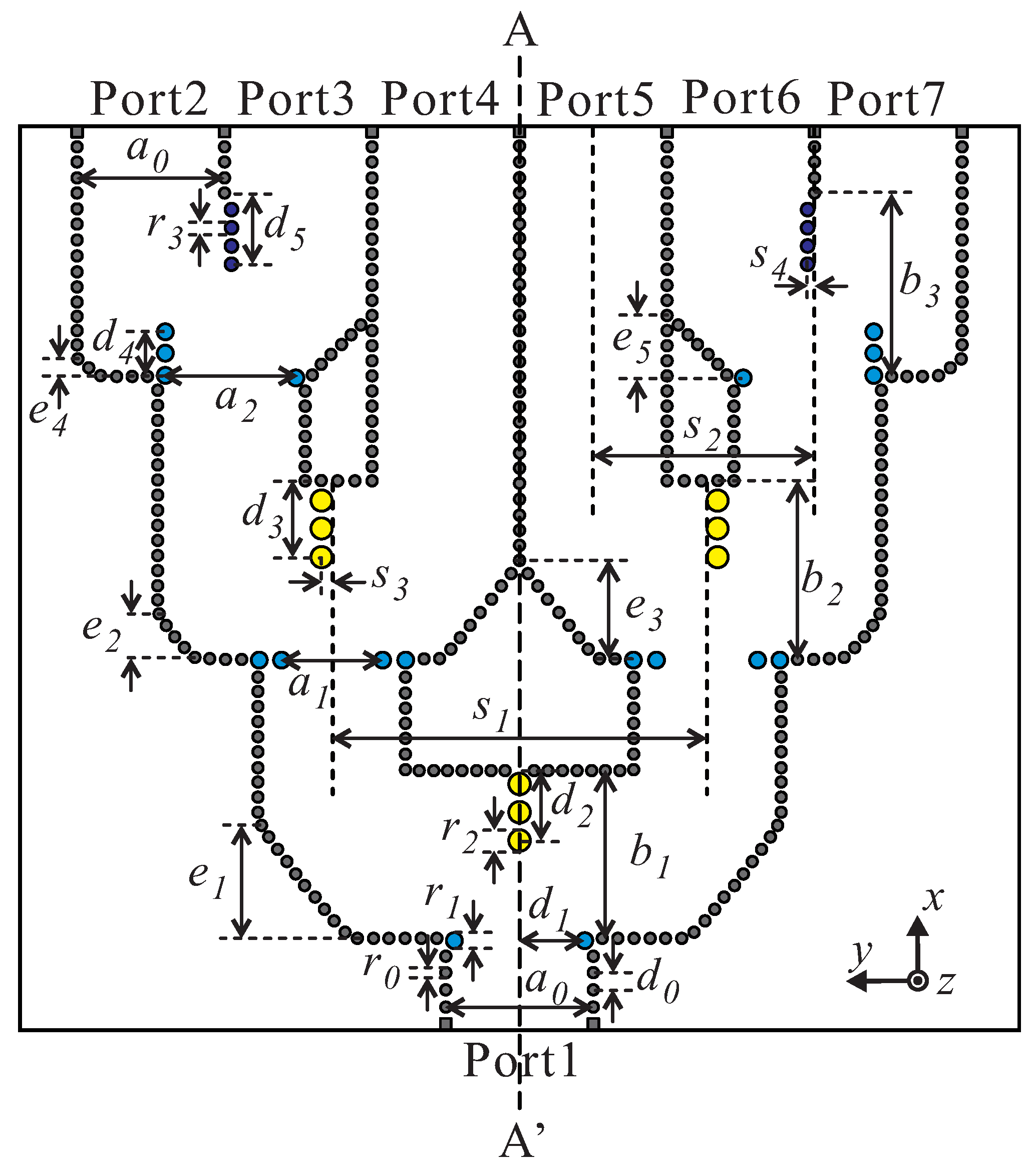
Figure 3 shows the scheme of the developed six-way unequal PD with 30 dB Taylor distribution to realize low SLLs in beam-patterns in E-plane. This divider is symmetric to the centerline A A . To achieve output coefficients satisfying Taylor weight values, it is required to design one equal T-junction PD and two unequal T-junction PDs that have different power-split ratios. The design process of the unequal T-junction PD starts from the design of an equal T-junction PD that has good impedance-matching characteristics. Next, an unequal power split can be achieved by adjusting the central posts ( s 3 and s 4 ), as illustrated in Figure 3. Note that the phase difference between the output ports of the PD can occur. To compensate for the phase difference, the conventional method is to change the path lengths of the SIW. However, this method tends to make the feeding network design complicated because of the need for accurate calculations of the proper path lengths for phase compensation. In our design, we can achieve the phase compensation by controlling the chamfer width ( e 2 , e 3 , e 4 , and e 5 ) of the SIW bends. Detailed values of the optimized parameters of the developed six-way unequal PD are listed in the caption of Figure 3.
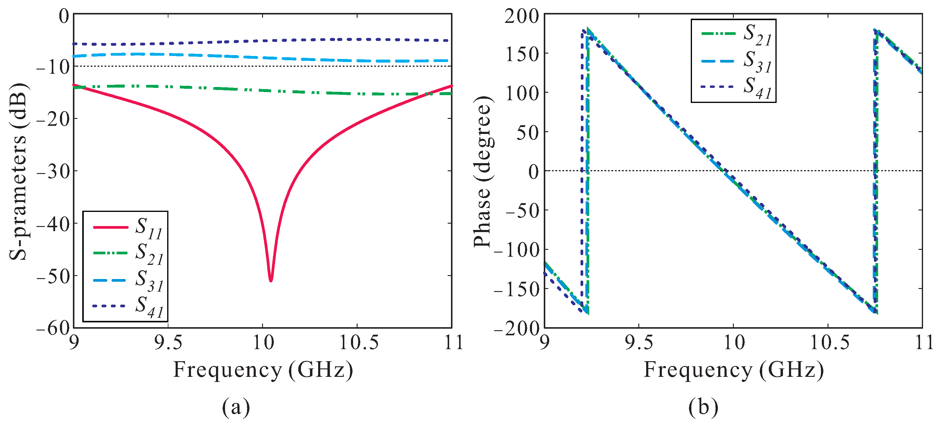
The simulated results of the S-parameters of the developed six-way unequal PD are illustrated in Figure 4. As shown in Figure 4a, the proposed divider exhibits a broad bandwidth ranging from 9.14 GHz to 10.90 GHz within | S 11 | ≤−15 dB. The simulated amplitude and phase of the transmission coefficients at the output ports (Ports 2–4) are depicted in Figure 4a and Figure 4b, respectively. It is shown that the unequal amplitudes and phase-balanced outputs are obtained at the output ports. A phase error of less than 5 is achieved. Table 1 shows the comparison between simulated transmission coefficients at 10 GHz and the 30 dB Taylor weight values. It depicts that the normalized values of the transmission coefficients are in good agreement with the Taylor weight ratios.

2.4. Two-Way Hybrid WG-to-SIW E-Plane PD

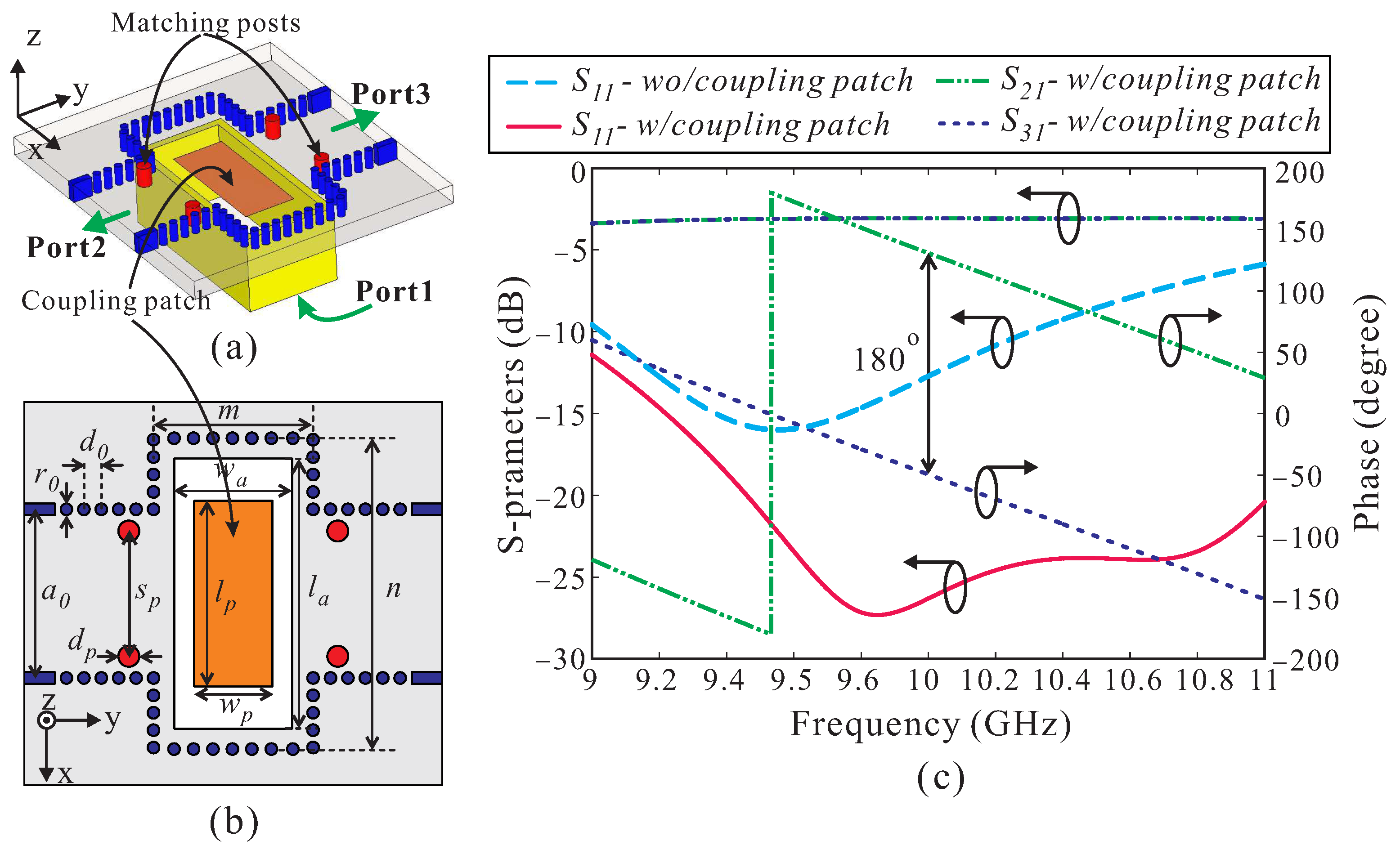
Figure 5a presents the geometry of the two-way hybrid WG-to-SIW E-plane PD. Four matching posts are located symmetrically at two outputs to improve the impedance matching. An aperture with a size of w a × l a , which is the same as that of the input waveguide (WR-90), is echted on the bottom metal layer of the SIW. A rectangular coupling patch is loaded inside the coupled aperture to improve the coupling between the input waveguide and SIW. The detailed design parameters of the proposed two-way hybrid WG-to-SIW E-plane PD are described in Figure 5b, and their values are shown in the caption of Figure 5. Figure 5c illustrates the simulated S-parameters. A two-way hybrid WG-to-SIW E-plane PD without a coupling patch is also simulated, and its simulated | S 11 | is also included in Figure 5c for comparison. As observed, the coupling patch not only improves impedance matching but also introduces an additional resonance, resulting in a much wider impedance bandwidth [21]. For the proposed two-way hybrid WG-to-SIW E-plane PD, a −15 dB reflection bandwidth ranges from 9.2 to over 11 GHz. The insertion loss of less than 0.22 dB is achieved. The phase difference between two output ports, namely, Port 2 and Port 3, is approximately 180 , with a phase error of less than 0.5 across the entire frequency band of interest.

2.5. Performance Enhancement

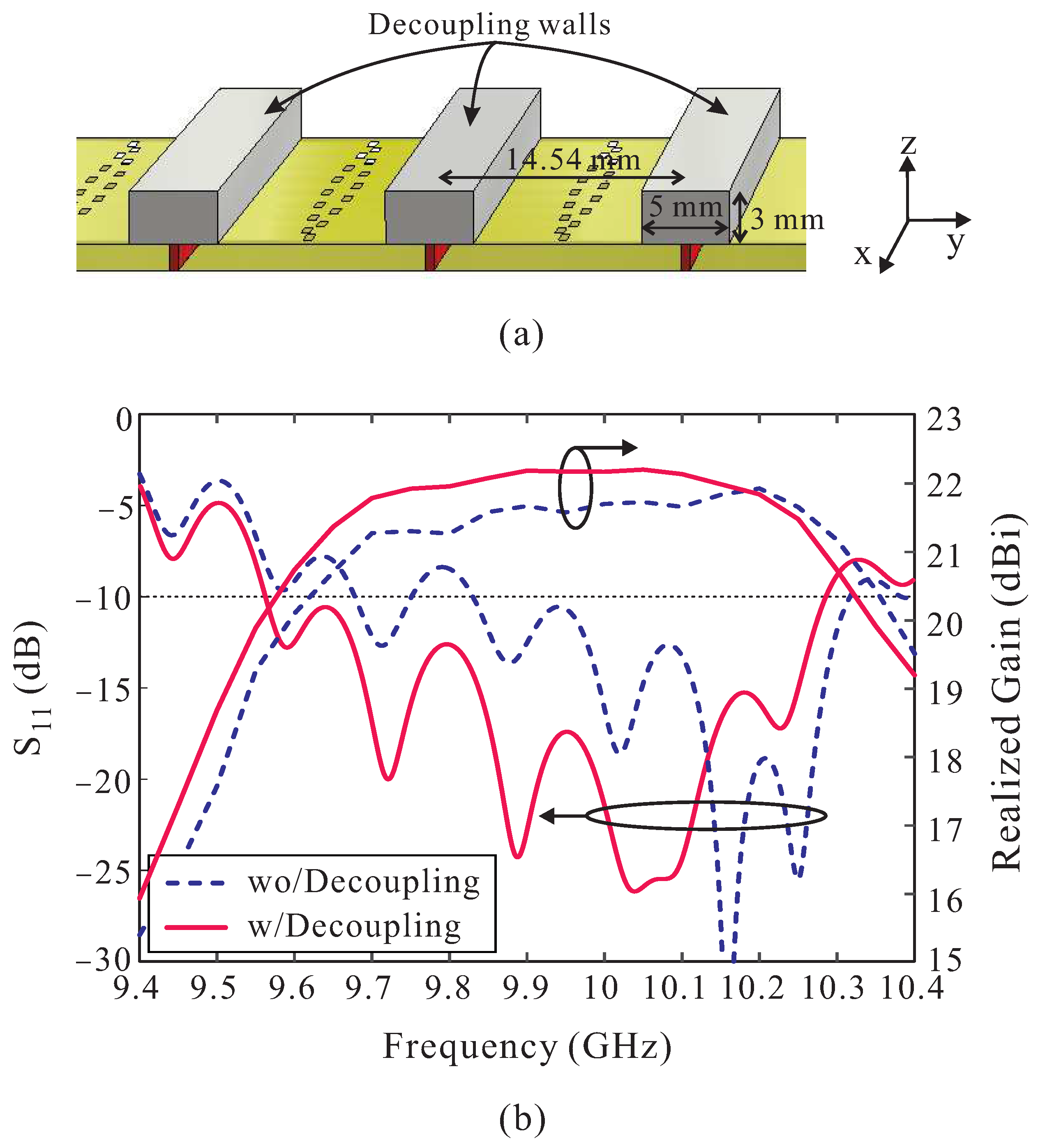
Although Elliott’s procedure can be effectively extended to design a 2-D SIW SAA, all mutual couplings, particularly the E-plane external mutual couplings, are only taken into account at the design frequency. Consequently, for slot arrays with wide bandwidths, the external mutual coupling in the E-plane is inaccurately accounted for at off-design frequencies, requiring time-consuming optimizations using commercial full-wave simulation software. In our design, for simplicity, we configured the 6 × 16 slot array by extending the 1 × 16 slot array directly. Then, to reduce the E-plane external mutual coupling between adjacent linear slot arrays, metallic decoupling walls were implemented. As shown in Figure 6a, the decoupling walls have a width of 5 mm and a height of 3 mm and are arranged in YoZ-plane (E-plane) with a distance of 14.54 mm. Figure 6b illustrates the simulated | S 11 | and the broadside realized gains of the proposed antenna with and without decoupling walls. As observed, the impedance matching (for | S 11 | ≤ −10 dB) is improved in the frequency range of 9.56 to 9.83 GHz owing to the E-plane external mutual coupling reduction. The proposed antenna with decoupling walls exhibits a −10 dB reflection bandwidth ranging from 9.56 to 10.28 GHz (7.26%), which is wider than that of the antenna without a decoupling wall (only 9.83–10.31 GHz (4.77%)). Moreover, the broadside gain of the proposed antenna is also enhanced by adding the decoupling walls. A maximum gain enhancement of approximately 0.61 dBi is achieved at 9.8 GHz.

3. Experimental Results and Discussion

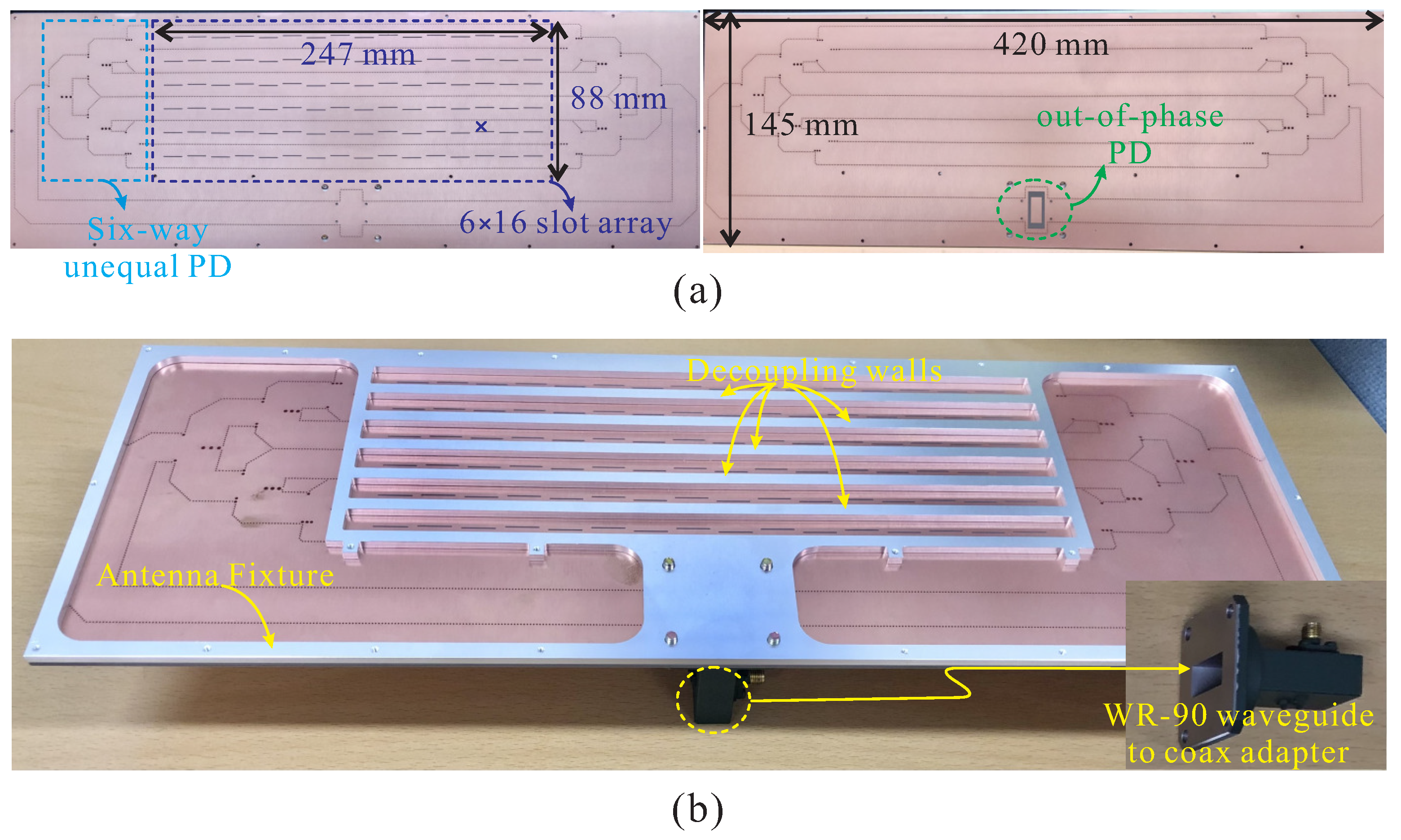
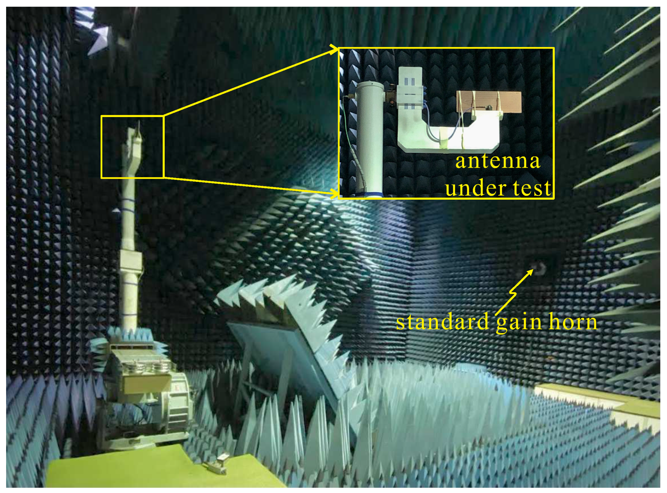
To verify the antenna performance, the proposed low-SLL differential-fed 6 × 16 SIW-based SAA is fabricated and tested. A photograph of the fabricated antenna is displayed in Figure 7 with an overall dimension of 420 mm × 145 mm × 4 mm. The 6 × 16 slot array occupies an area of 247 mm × 88 mm, which corresponds to 8.23 λ 0 × 2.93 λ 0 ( λ 0 is the free-spaced wavelength at 10 GHz). The decoupling walls and the antenna fixture are made of alumina and are fixed to the substrate by small metallic screws. A commercial WG-to-coax adapter (product number: 16094-SF40) is used to feed the fabricated antenna. An Agilent E8362C network analyzer is used to measure the reflection coefficient. The radiation properties are measured in an anechoic chamber with a dimension of 16 m × 11 m × 9 m, as shown in Figure 8.
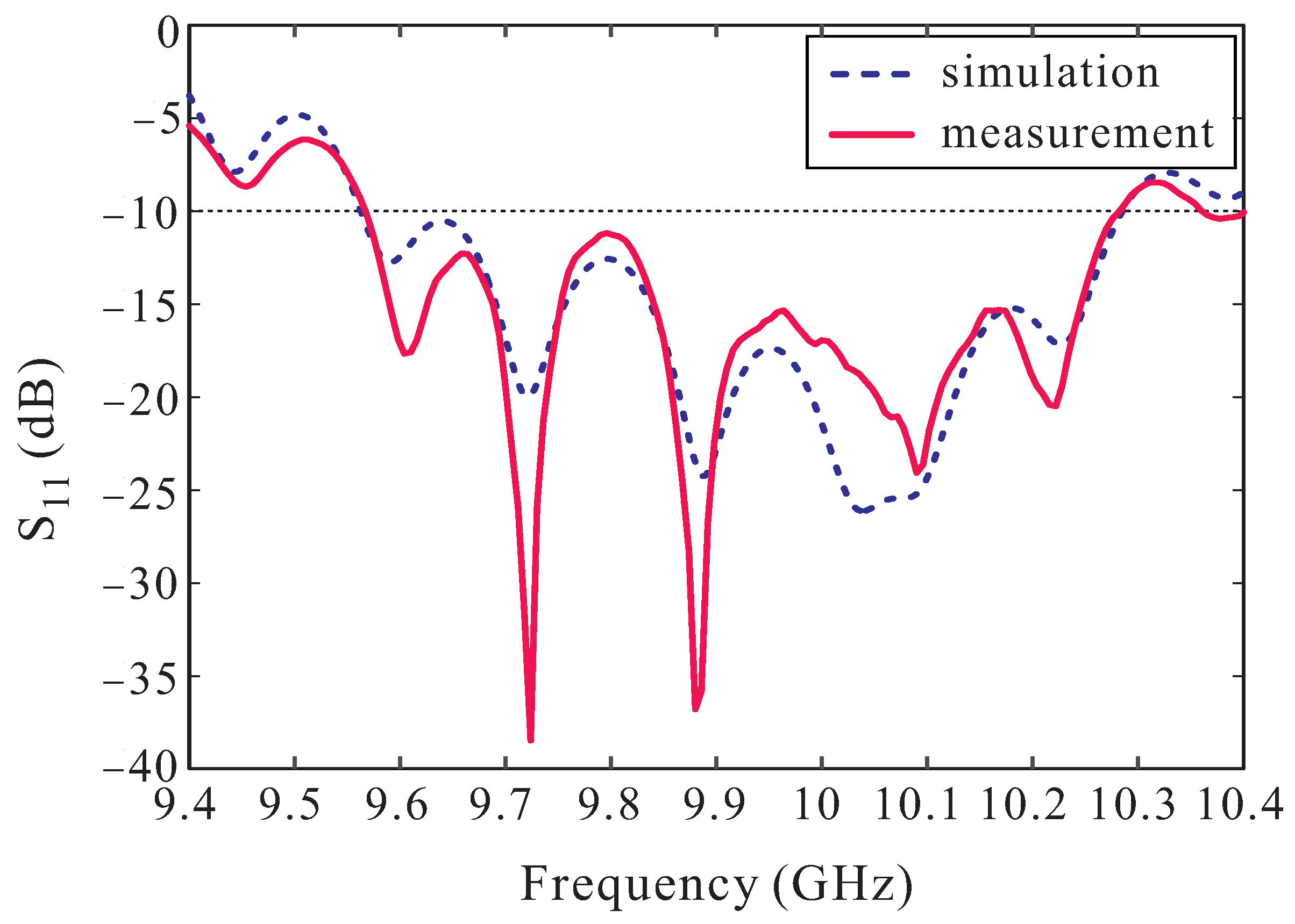
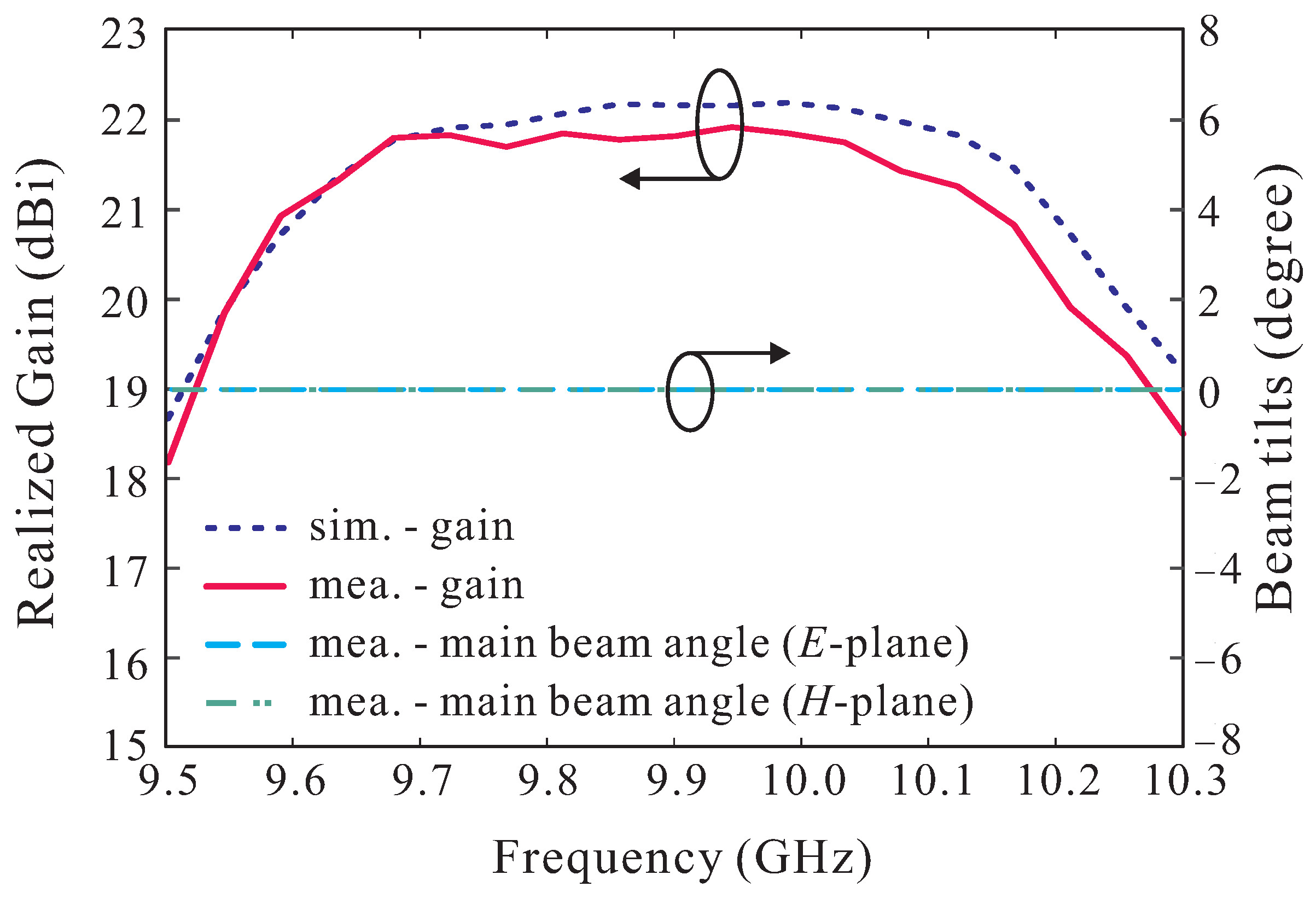
Figure 9 illustrates the measured and simulated reflection coefficients versus frequency. The measurement agrees well with the simulation. The measured −10 dB reflection bandwidth ranges from 9.57 to 10.28 GHz, i.e., a relative bandwidth of 7.15%. The measured and simulated realized gains in the broadside direction against the frequency are illustrated in Figure 10. The realized gain ranging from 20.30 to 21.92 dBi is obtained from the measurement result, while the simulated one is ranging from 20.72 to 22.18 dBi. A slight deviation is found between the simulation and measurement, which is mainly attributed to the fabrication tolerances and the measurement errors. Figure 10 also plots the measured main beam angles in the E- and H-planes versus frequency of the proposed low-SLL, differential-fed, SIW-based SAA. In reference to the figure, the zero beam squinting is observed over the entire measured frequency band for both the E- and H-planes.
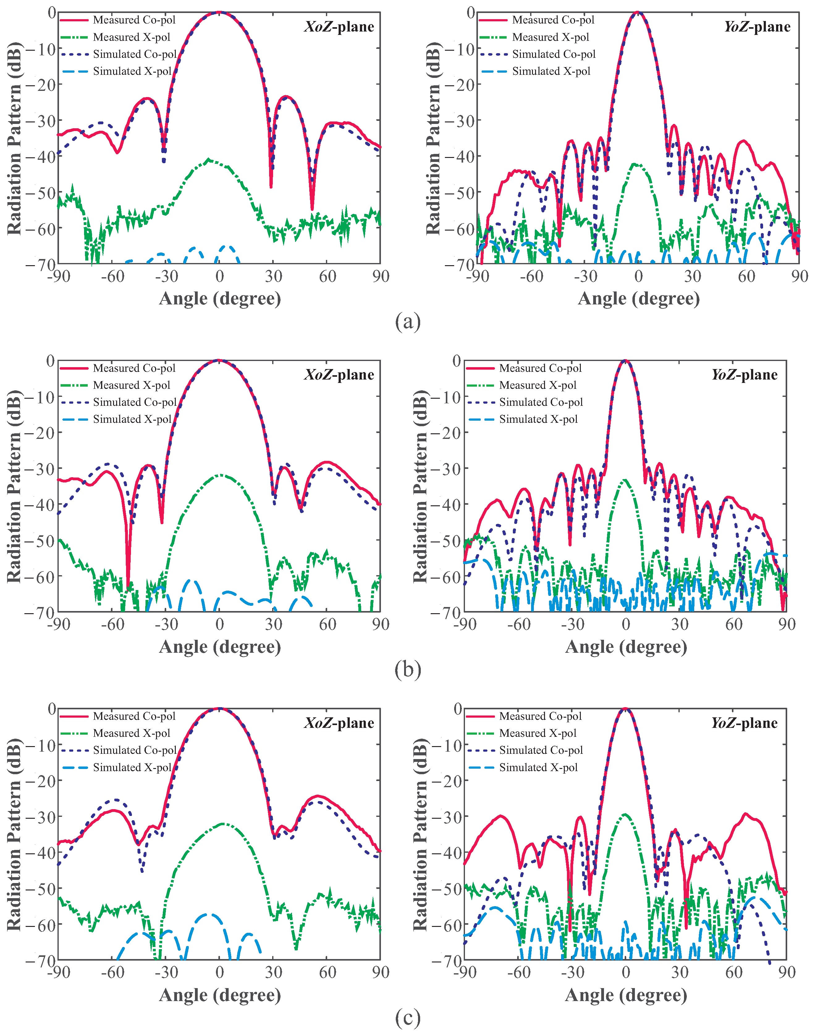
Figure 11 shows the simulated and measured radiation patterns at 9.6, 10, and 10.25 GHz in both the YoZ-plane (E-plane) and the XoZ-plane (H-plane). The radiation patterns are measured at elevation angles ranging from −90 to +90 , for co- and cross-polarizations. The main beam direction in the YoZ- and XoZ- planes stays in the boresight direction at all three frequencies. At 10 GHz, the peak measured SLLs are −29.1 dB inthe E-plane and −29.4 dB in the H-plane, which are close to the ideal value of −30 dB. The peak measured SLLs in the E-plane are increased to −23.4 dB at 9.6 GHz and to −24.4 dB at 10.25 GHz. This is because the six-way unequal power divider is designed and optimized at 10 GHz. Meanwhile, the peak measured SLLs in the H-plane are −31.5 dB and −29.8 dB at 9.6 GHz and 10.25 GHz, respectively. Furthermore, as observed in Figure 11, the measured cross-polarization level of less than −30 dB is obtained in the boresight direction. A comparison between the proposed antenna and the other low-SLL, SIW-based SAAs is conducted and listed in Table 2. It can be seen from the comparison that the proposed antenna has a much wider impedance BW than previous designs while maintaining low SLL features in both the E-plane and H-plane. Despite having a lower SLL than the proposed antenna, the antenna in [13] was designed with a goal of −35 dB SLL.

4. Conclusions

A low-cost, high-gain low-SLL, differential-fed, SIW-based SAA with zero beam squint is presented, fabricated, and tested. The proposed antenna is realized on a single-layered Taconic TLY-5 substrate. By employing the differential feeding structure, the proposed antenna achieved a stable broadside main beam with a low SLL across the entire operating band. The experimental results demonstrate that the proposed antenna has a −10 dB reflection bandwidth of 7.15% (9.57–10.28 GHz) and a gain ranging from 20.30 to 21.92 dBi. In addition, a peak SLL ≤ −29.1 dB and a cross-polarization level of less than −30 dB are obtained at 10 GHz. With these advantages, the proposed low-SLL, differential-fed, SIW-based SAA is an excellent candidate for several applications, such as satellite communication and radar systems.

Author Contributions

Conceptualization, T.V.T., S.T.-V., K.-Y.L., Y.Y., and K.C.H.; methodology, T.V.T., S.T.-V., and K.C.H.; simulation, T.V.T. and S.T.-V.; validation and formal analysis, T.V.T., S.T.-V., K.-Y.L., Y.Y., and K.C.H.; investigation, T.V.T. and S.T.-V.; resources and data curation, T.V.T. and S.T.-V.; writing—original draft preparation, T.V.T., S.T.-V., and K.C.H.; writing—review and editing, T.V.T., S.T.-V., and K.C.H.; supervision, K.-Y.L., Y.Y., and K.C.H.; and project administration, K.C.H. All authors have read and agreed to the published version of the manuscript.

Funding

This work was supported by Institute of Information and Communications Technology Planning and Evaluation (IITP) grant funded by the Korean government Ministry of Science and Information and Communication Technologies (MSIT) (no. 2020-0-00261, the development of a low-power/low-delay/self-power suppliable RF simultaneous information and power transfer system and stretchable electronic epineurium for wireless nerve bypass implementation).

Institutional Review Board Statement

Not applicable.

Informed Consent Statement

Not applicable.

Data Availability Statement

All data have been included in study.

Conflicts of Interest

The authors declare no conflict of interest.

References

  1. Yeoh, Y.-S.; Min, K.-S. Characteristics of 6 × 26 slotted waveguide array antenna for wave monitoring radar system. J. Electromagn. Eng. Sci. 2021, 21, 439–447. [Google Scholar] [CrossRef]
  2. Trinh-Van, S.; Song, S.C.; Seo, S.H.; Hwang, K.C. Waveguide slot array antenna with a hybrid-phase feed for grating lobe reduction. Int. J. Antennas Propag. 2016, 53, 2662–2673. [Google Scholar] [CrossRef] [Green Version]
  3. Purnamirza, T.; Ibrahim, I.M.; Susanti, R.; Sutoyo; Mylyono; Radiles, H.; Rahmi, D. Cutting technique for constructing small radial line slot array antennas. J. Electromagn. Eng. Sci. 2021, 21, 35–43. [Google Scholar] [CrossRef]
  4. Yu, T.; Lee, H.; Park, S.-J.; Nam, S. A uniform heating technique for cavity in volatile organic sompound (VOC) removal system using slotted waveguide array. J. Electromagn. Eng. Sci. 2021, 21, 126–133. [Google Scholar] [CrossRef]
  5. Rengarajan, S.R.; Shaw, G.M. Accurate characterization of coupling junctions in waveguide-fed planar slot arrays. IEEE Trans. Microw. Theory Tech. 1994, 42, 2239–2248. [Google Scholar] [CrossRef]
  6. Casula, G.A.; Mazzarella, G. A direct computation of the frequency response of planar waveguide slot arrays. IEEE Trans. Antennas Propag. 2004, 52, 1909–1912. [Google Scholar] [CrossRef]
  7. Elliott, R.; O’Loughlin, W. The design of slot arrays including internal mutual coupling. IEEE Trans. Antennas Propag. 1986, 34, 1149–1154. [Google Scholar] [CrossRef]
  8. Iftikhar, A.; Shafique, M.F.; Farooq, U.; Khan, M.S.; Asif, S.M.; Fida, A.; Ijaz, B.; Rafique, M.N.; Mughal, M.J.; Ur-rehman, M. Planar SIW leaky wave antenna with wlectronically reconfigurable E- and H-plane scanning. IEEE Access 2019, 7, 171206–171213. [Google Scholar] [CrossRef]
  9. Hong, S.-J.; Lee, M.-P.; Kim, S.; Lim, J.-S.; Kim, D.-W. A Ku-band low-loss traveling-wave power divider using a hollow substrate integrated waveguide and tts microstrip transition. J. Electromagn. Eng. Sci. 2020, 20, 131–138. [Google Scholar] [CrossRef]
  10. Xu, F.; Wu, K. Guided-wave and leakage characteristics of substrate integrated waveguide. IEEE Trans. Microw. Theory Tech. 2005, 53, 66–73. [Google Scholar]
  11. Lim, J.-H.; Lee, J.W.; Lee, T.-K.; Lee, H.-C.; Lee, S.-G.; Ryu, S.-B.; Yoon, S.-S. Performance evaluation of a modified SweepSAR mode for quad-pol application in SAR systems. J. Electromagn. Eng. Sci. 2020, 20, 199–206. [Google Scholar] [CrossRef]
  12. Xu, J.F.; Hong, W.; Chen, P.; Wu, K. Design and implementation of low sidelobe substrate integrated waveguide longitudinal slot array antennas. IET Microw. Antennas Propag. 2009, 3, 790–797. [Google Scholar] [CrossRef]
  13. Yang, H.; Montisci, G.; Jin, Z.; Liu, Y.; He, X.; Mazzarella, G. Improved design of low sidelobe substrate integrated waveguide longitudinal slot array. IEEE Antennas Wireless Propag. Lett. 2015, 14, 237–240. [Google Scholar] [CrossRef]
  14. Dewantari, A.; Kim, J.; Scherbatko, I.; Ka, M.H. A sidelobe level reduction method for mm-Wave substrate integrated waveguide slot array antenna. IEEE Antennas Wireless Propag. Lett. 2019, 18, 1557–1561. [Google Scholar] [CrossRef]
  15. Park, S.; Tsunemitsu, Y.; Hirokawa, J.; Ando, M. Center feed single layer slotted waveguide array. IEEE Trans. Antennas Propag. 2006, 54, 1474–1480. [Google Scholar] [CrossRef]
  16. Kim, D.; Nam, S. Excitation control method for a low sidelobe SIW series slot array antenna with 45 linear polarization. IEEE Trans. Antennas Propag. 2013, 61, 5807–5812. [Google Scholar] [CrossRef]
  17. Ma, W.; Cao, W.; Wang, C.; Shi, S.; Zhang, B. Planar high-gain millimeter-wave slotted SIW cavity antenna array with low sidelobe and grating lobe levels. Int. J. Antennas Propag. 2022, 2022, 8431611. [Google Scholar] [CrossRef]
  18. Xu, J.; Chen, Z.N.; Qing, X. CPW center-fed single-layer SIW slot antenna array for automotive radars. IEEE Trans. Antennas Propag. 2014, 62, 4528–4536. [Google Scholar] [CrossRef]
  19. Li, T.; Meng, H.; Dou, W. The analysis of broadband slotted antenna array. In Proceedings of the 2nd Asia-Pacific Conference on Antennas and Propagation, Xi’an, China, 5–7 August 2013; pp. 15–16. [Google Scholar]
  20. Tyagi, Y.; Mevada, P.; Chakrabarty, S.; Jyoti, R. High-efficiency broadband slotted waveguide array antenna. IET Microw. Antennas Propag. 2017, 11, 1401–1408. [Google Scholar] [CrossRef]
  21. Mohamed, I.; Sebak, A. Broadband transition of substrate-integrated waveguide-to-air-filled rectangular waveguide. IEEE Microw. Wireless Compon. Lett. 2018, 28, 966–968. [Google Scholar] [CrossRef]
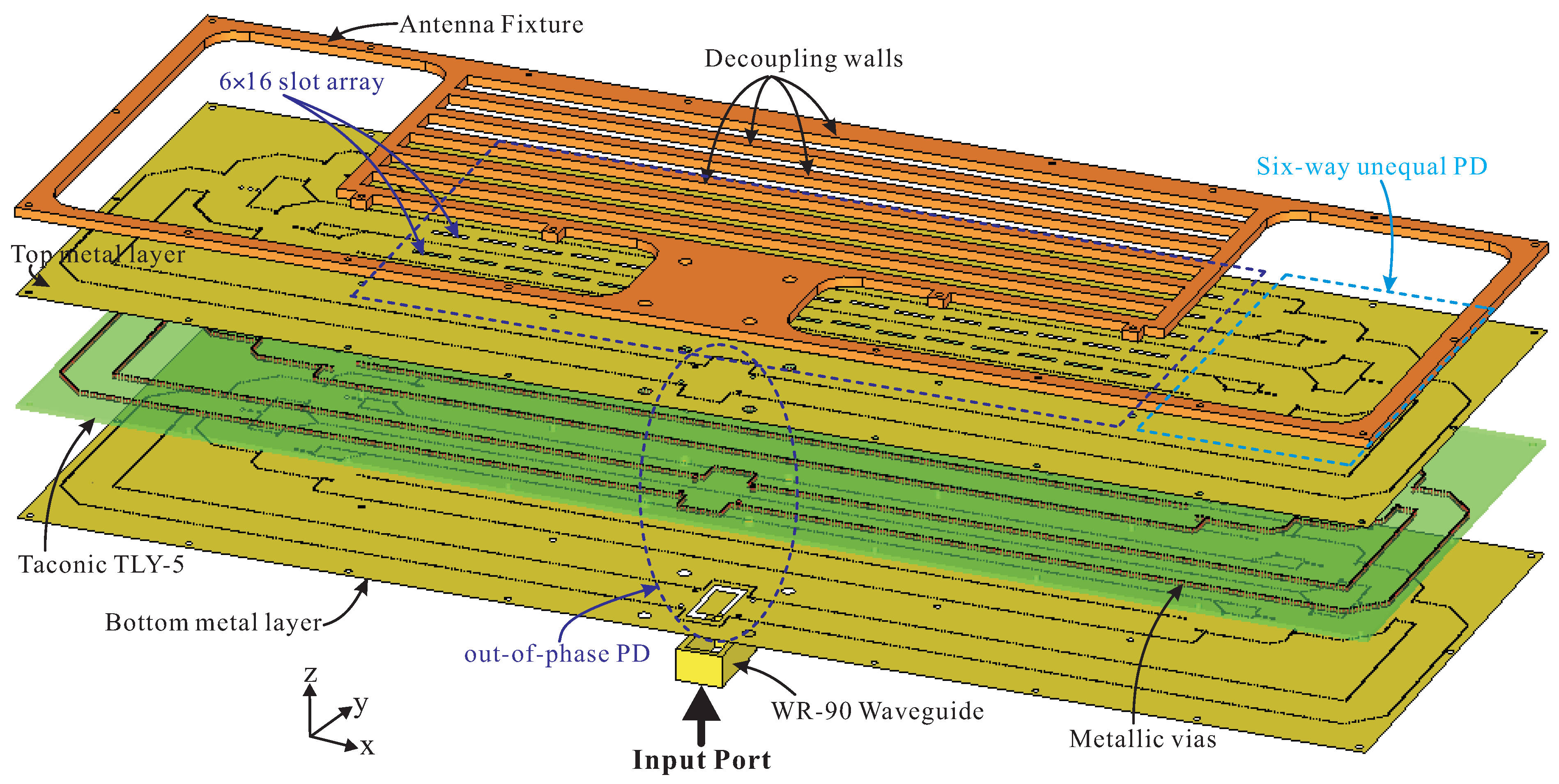
Figure 1. 3-D exploded view of the proposed low-SLL, differential-fed, SIW-based SAA.
Applsci 12 10826 g001
Figure 2. (a) Geometry of the differential-fed 1 × 16 linear slot array (dimensions are l 1 = 11.566, x 1 = 0.172, l 2 = 11.386, x 2 = −0.251, l 3 = 11.420, x 3 = 0.333, l 4 = 11.466, x 4 = −0.440, l 5 = 11.530, x 5 = 0.544, l 6 = 11.590, x 6 = −0.638, l 7 = 11.642, x 7 = 0.707, l 8 = 11.680, and x 8 = −0.741 (Units: mm)), (b) end-fed 1 × 16 linear slot array, (c) center-fed 1 × 16 linear slot array, (d) reflection coefficients, and (e) SLLs and main beam angles.
Applsci 12 10826 g002
Figure 3. Geometry of the six-way unequal PD. Dimensions are a 0 = 14.54, a 1 = 11.71, e 4 = 1.17, s 4 = 0.55, a 2 = 13.04, e 5 = 5.06, d 0 = 1, d 1 = 6.52, b 1 = 14.54, r 0 = 0.5, r 1 = 0.50, d 2 = 6.58, b 2 = 14.54, r 2 = 0.68, d 3 = 5.81, b 3 = 14.88, r 3 = 0.42, d 4 = 3.00, e 1 = 10.03, s 1 = 37.04, d 5 = 6.26, e 2 = 3.54, s 2 = 21.81, e 3 = 7.65, and s 3 = 1.00 (units: mm).
Applsci 12 10826 g003
Figure 4. Simulated S-parameters of the six-way unequal PD: (a) amplitudes and (b) phases.
Applsci 12 10826 g004
Figure 5. (a) Perspective view, (b) top view and (c) simulated S-parameters of the two-way hybrid WG-to-SIW E-plane PD. Dimensions are a 0 = 14.54, r 0 = 0.5, d 0 = 1, n = 28.74, m = 13.75, l a = 22.86, w a = 10.16, l p = 16, w p = 6.75, s p = 10.8, and d p = 1.5 (Units: mm).
Applsci 12 10826 g005
Figure 6. (a) Implementation of the decoupling walls; (b) effect of the decoupling wall on | S 11 | and realized gain of the proposed low-SLL, differential-fed, SIW-based SAA.
Applsci 12 10826 g006
Figure 7. Photograph of the proposed low-SLL, differential-fed, SIW-based SAA: (a) top view and bottom view and (b) overall view.
Applsci 12 10826 g007
Figure 8. Far-field measurement setup of the proposed low-SLL, differential-fed, SIW-based SAA.
Applsci 12 10826 g008
Figure 9. Measured and simulated reflection coefficients.
Applsci 12 10826 g009
Figure 10. Simulated and measured realized gains and main beam angles.
Applsci 12 10826 g010
Figure 11. Simulated and measured normalized radiation patterns of the proposed low-SLL, differential-fed, SIW-based SAA in the YoZ-plane (E-plane) and the XoZ-plane (H-plane): (a) 9.6 GHz, (b) 10 GHz, and (c) 10.25 GHz.
Applsci 12 10826 g011
Table 1. Comparison between Taylor weight ratio and S-parameters.
Port No.S-Parameters (dB/Linear)Normalized S-ParametersTaylor Weight (−30 dB SLL)
Port 2, 7−14.66/0.180.330.32
Port 3, 6−8.41/0.380.690.69
Port 4, 5−5.18/0.551.001.00
Table 2. Performance comparison of the planar low-SLL, SIW-based SAAs.
Ref.Element Number f 0 (GHz)Feeding MechanismImp. BW (%)Peak Gain (dBic)Peak SLL (dB)Size ( λ 0 2 )
[12]16 × 1610End feed2.7024.5−31.3 dB (E-plane)9×8.67
−30.3 dB (H-plane)
[13]10 × 1010End feed2.4022−32.3 dB (E-plane)7×5.67
−33.8 dB (H-plane)
[17]4 × 1627.5Center feed2.1821.4−17.9 dB (E-plane)10.3×5.7
−19.1 dB (H-plane)
[18]4 × 3224Center feed1.7122.8−13.5 dB (E-plane)15.6×3.2
−21.0 dB (H-plane)
Proposed6 × 1610Differential feed7.1521.92−29.1 dB (E-plane)14×4.83
Design −29.4 dB (H-plane)
λ 0 is the wavelength in free space at the designed frequency of the corresponding antenna, Imp. BW: Impedance bandwidth.
Publisher’s Note: MDPI stays neutral with regard to jurisdictional claims in published maps and institutional affiliations.