Abstract
The instantaneous cutting energy efficiency of a milling cutter is an important index to evaluate the cutting performance of the milling cutter. The existing models for cutting energy efficiency ignore the differences in the instantaneous cutting energy efficiency of each cutter tooth. In this work, according to the influence of milling vibration on instantaneous cutting posture and the input and output energy, a correlation model of the instantaneous cutting energy efficiency of a milling cutter and its cutter teeth was established. Using the cutting-force energy efficiency and the specific cutting energy and their distribution on the cutting edge of the cutter teeth, the dynamic relationship between the effective cutting energy transfer and conversion of the milling cutter was characterized. The instantaneous cutting-force energy efficiency and specific cutting energy were calculated. The formation of the dynamic distribution of the cutting energy efficiency was unveiled. Finally, an identification method for distributive variation in the instantaneous cutting energy efficiency of the milling cutter was proposed. The response of the distribution of the instantaneous cutting energy efficiency was studied and verified using experiments. The results showed that there was high similarity and good agreement between the calculated and measured results of the cutting energy efficiency of the milling cutter.
1. Introduction
Milling cutters are developing high energy-utilization rates [1]. The cutting mode of the multi-cutter tooth rotations of a milling cutter determines that the essence of its cutting process is the intermittent cutting of the cutter teeth. The impact and vibration caused by the intermittent cutting of the cutter teeth make the cutting layer change irregularly [2]. This leads to constant variation in the instantaneous cutting force and cutting energy consumption, which directly affects the energy-utilization rate of the milling cutter [3]. The instantaneous cutting energy efficiency directly reflects the level of and changes in the milling cutter’s energy-utilization rate. The instantaneous cutting-force energy efficiency and the specific cutting energy are the main characteristic variables needed to reveal the milling cutter’s instantaneous cutting energy efficiency. The cutting energy efficiency is related to the instantaneous cutting-layer parameters, the cutting-force energy consumption, the shear energy consumption and the input energy of the milling cutter.
Instantaneous cutting-force energy efficiency includes tangential-force energy efficiency and shear energy efficiency, which mainly reflect the relationships between various energies in the cutting process of the milling cutter. Among them, tangential-force energy efficiency refers to the proportion of tangential-force energy consumption in the input energy, and shear energy efficiency refers to the proportion of shear energy consumption in tangential-force energy consumption [4,5]. Instantaneous specific cutting energy includes specific tangential-force energy and specific shear energy, which reflect the relationship between the milling cutter removal volume and energy consumption [6]. Among them, the specific tangential-force energy refers to the ratio of tangential-force energy consumption-to-cutting volume, and the specific shear energy refers to the ratio of shear energy consumption-to-cutting volume. Therefore, it is of great significance to study the instantaneous cutting energy-efficiency distribution of a milling cutter under vibration and establish a model with the correct energy efficiency for improving the energy efficiency and achieving high-energy-efficiency milling of the milling cutter.
The distribution of instantaneous energy efficiency and specific cutting energy on the cutting edge is the key to revealing variation in the instantaneous cutting energy efficiency of the milling cutter [7,8]. The direction of instantaneous cutting velocity at each point on the cutting edge is different when using a helical end-mill. The milling cutter and cutter teeth will have different offsets in the workpiece coordinate system under milling vibration. The offset leads to changes in the instantaneous cutting contact relationship between the cutter teeth and the workpiece. The contact relationship results in a constant change in the size and direction of the cutting force at each point on the cutting edge, which causes different energy-consumption values at each point of the cutter teeth [9]. In existing studies on the instantaneous cutting-force energy efficiency and specific cutting energy of milling cutters, it was assumed that the instantaneous cutting behavior of each cutter tooth had the same change. They ignored the differences between the instantaneous cutting energy efficiency of each cutter tooth under milling vibration, as well as cutter tooth error. It is impossible to reveal the distribution of the instantaneous cutting energy efficiency of a milling cutter along different cutting edges using the above methods.
In recent years, research on the cutting force and cutting energy of milling cutters has mainly included the following aspects. Ducroux et al. developed a parametric cutting-force model based on complete geometric definition, and used the cutting edge discretization method to accurately determine the cutting thickness [10]. Luan et al. developed an energy-consumption model based on micro-element cutting force in a metal removal process, which could be used to evaluate and optimize milling power consumption [11]. Yuan et al. proposed an energy-efficiency-state identification method based on integrated empirical mode decomposition, principal component analysis and independent component analysis [12]. Cai et al. established a low- and high-energy-state feature extraction method by combining continuous wavelet transform with fast independent component analysis [13]. Jamil et al. established evaluation criteria for a milling energy-efficiency model and obtained highly efficient cutting parameters [14]. Zhou et al. studied the influence of micro-milling cutting parameters on milling force [15]. Zhang et al. considered the process nonlinearity caused by tool runout and cycloid trajectory of the cutting edge, and proposed a new energy-consumption analysis model and optimization method for the cutting parameters [16]. The above methods point out the direction for research on the instantaneous energy efficiency of milling cutters, but cannot unveil the differences in the energy-transfer relationship in the cutting process of each cutter tooth. It is necessary to further study the cutting-force energy efficiency of cutter teeth.
In their study of the instantaneous cutting layer and specific cutting energy of milling cutters, Płodzień studied the influence of the change in cutting-layer volume on surface roughness, cutting vibration and cutting force [17]. Shin et al. used a regression model and neural network model to predict energy consumption [18]. Zhu et al. used exponential function (SECI) to describe the change in specific cutting energy with average undeformed chip thickness and reflected the processing performance of different parameters [19]. Kundrák et al. considered the influence of different cutting parameters on specific cutting energy and established a relationship between specific energy and the chip ratio [20]. He et al. proposed a prediction analysis model of specific cutting energy based on the material removal mechanism, according to the influence of cutting parameters on specific cutting energy [21]. Liu et al. established a new power regression model to predict the net specific cutting energy at the process level [22]. The above methods have important guiding significance for calculation of the distribution of the instantaneous specific cutting energy of a milling cutter. However, they cannot reveal the distribution of the instantaneous specific cutting energy along the cutting edge of the cutter teeth or the differences in the variation in the specific cutting energy of each cutter tooth. Thus, they cannot correctly reflect the variation in the instantaneous specific cutting energy of the milling cutter.
Therefore, in this research, instantaneous cutting-force energy efficiency and specific cutting energy on the cutting edge were used to quantitatively characterize the relationship between energy transfer and conversion in the cutting process of a milling cutter. The influence of milling vibration on the instantaneous cutting upper and lower boundaries, instantaneous cutting velocity, shear direction velocity and instantaneous cutting volume of the cutter teeth were studied. The modeling of instantaneous cutting-force energy consumption and shear energy consumption of the cutter teeth were established. The calculation model of instantaneous cutting-force energy efficiency and specific cutting energy were constructed using the energy-consumption distribution and cutting-layer parameters. The validity of the model was studied by changing the cutting parameters and cutter tooth error. The correctness of the instantaneous cutting energy-efficiency calculation model of milling cutter was verified using the gray correlation analysis method.
2. Characterization of Instantaneous Cutting Energy Transmission and Conversion of Milling Cutter
The milling cutter structure, cutting parameters and milling vibration directly determined the instantaneous cutting behavior of the milling cutter and cutter teeth, and affected the energy input and output of the instantaneous cutting of the milling cutter. Among them, the instantaneous cutting posture, energy composition and distribution of the end mill and its cutter teeth under vibration are shown in Figure 1.
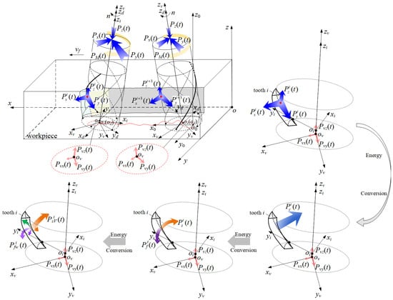
Figure 1.
Instantaneous cutting posture and energy of milling cutter under vibration.
In Figure 1, o-xyz is the workpiece coordinate system. o0-x0y0z0 is the milling cutter’s cutting coordinate system without vibration. ov-xvyvzv is the milling cutter’s cutting coordinate system with vibration. od-xdydzd is the milling cutter structure coordinate system. oi-xiyizi is the cutter tooth coordinate system. n is the spindle speed. vf is the feed velocity of milling cutter. PM(t) is torque input energy of the milling cutter. Px(t), Py(t) and Pz(t) are the energy input to the milling cutter along the x, y and z directions, respectively. Pxi(t), Pyi(t) and Pzi(t) are the energy consumption of the ith cutter tooth along the x, y and z directions, respectively. Pvx(t), Pvy(t) and Pvz(t) are the input energy of the vibration of the milling cutter along the x, y and z directions, respectively. Pci(t) is the tangential-force energy efficiency of the ith cutter tooth. Psi(t) is the shear energy efficiency of the ith cutter tooth. PsVi(t) is the energy efficiency of milling volume of the ith cutter tooth. Pshi(t) is the heat generated during the shearing process of the cutter teeth. Pfi(t) is the friction energy consumption of the ith cutter tooth. Pfwi(t) is the wear energy consumption of the ith cutter tooth. Pfhi(t) is heat generated by the friction and wear of the cutter teeth.
According to Figure 1, the trajectory equation of any point of the cutting edge of the milling cutter in the workpiece coordinate system can be written as:
where (xi, yi, zi) is the coordinates of any point of the cutting edge in the cutter tooth coordinates system. The cutting edge equation was constructed based on the initial helical edge structure. The cutting edge equation is shown in Equation (2), which ignores the influence of tooth wear on the helical edge shape. A1, A2 and A3 are translation matrices, and T1, T2, and T3 are rotation matrices, as shown in Equations (3)–(8).
where Δri is the radial error of the ith cutter tooth.
where ap is the cutting depth. ae is the cutting width. Δci is the axial error of the ith cutter tooth. β is the helix angle of the cutter tooth. φsi is the angle between the cutter teeth. φq(t) is the instantaneous angle between the yd axis and yv axis in the xvovyv plane.
According to Figure 1, during the milling process, the energy input from the main drive system and feed system of the machine tool was transmitted to the milling cutter and workpiece through the cutter body, the functional interface of each cutter tooth and the cutting layer. The energy output of the milling cutter not only included the cutting energy consumption of the cutter tooth, but also included a variety of additional energy consumption caused by the intermittent cutting of the cutter tooth. There were a variety of transmission and conversion relationships between the instantaneous energy input and output of the milling cutter, as shown in Figure 2.
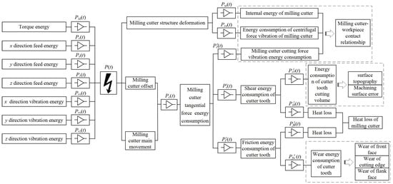
Figure 2.
Energy transfer and transformation in milling process of milling cutter.
In Figure 2, P(t) is the input energy. Pc(t) is the tangential-force energy consumption. Pie(t) is the internal energy of the milling cutter. Pce(t) is the energy consumption of the centrifugal force vibration of the milling cutter. Pcv(t) is the milling cutter’s cutting-force vibration energy consumption.
From Figure 1 and Figure 2, the energy input of milling cutter instantaneous cutting can be expressed as
where P1(t) is the input energy of the machine tool feed system. P2(t) is the additional vibration energy of the feed system. Additionally, P3(t) is the additional energy provided by the machine tool for the energy consumption of the milling cutter.
The energy output of the milling cutter instantaneous cutting can be written as
where Pd(t) is the additional energy consumption of the milling cutter energy consumption.
Using Equations (10)–(16), analyzing the energy allocation of the milling cutter in the cutting process, the efficiency of converting the instantaneous input energy of the milling cutter into the instantaneous tangential-force energy can be solved, as shown in Equation (17). Among them, the additional energy provided by the machine tool in the energy consumption of the milling cutter was small and could not be calculated quantitatively, so it was ignored.
From Equation (14), the shear deformation energy of the milling cutter acting on the cutting deformation area of the workpiece was the effective cutting energy to form the machined surface. The efficiency of converting the instantaneous tangential-force energy of the milling cutter into instantaneous shear energy can be derived as shown in Equation (18). Among them, the instantaneous tangential-force energy consumption of the milling cutter was composed of the tangential-force energy consumption of different cutter teeth involved in cutting. The energy consumption of the instantaneous shearing force of the milling cutter was composed of the energy consumption of the shearing force of different cutter teeth involved in cutting.
From this, it can be seen that the relationship between the transmission and conversion of the instantaneous cutting-force energy efficiency of the milling cutter can be expressed as
where, eci(z,t) is the instantaneous specific tangential-force energy of the milling element on the cutting edge of the cutter tooth. esi(z,t) is the instantaneous specific shear energy of the milling element. pci(z,t) is the distribution function of the instantaneous tangential force energy consumption of the milling micro-element. psi(z,t) is the distribution function of the instantaneous shearing energy consumption of the milling micro-element. Vi(z,t) is the instantaneous cutting volume of the milling micro-element.
From Equations (19)–(21), the instantaneous cutting energy consumption and effective cutting energy-efficiency distribution on each cutting edge directly determined the overall instantaneous effective cutting energy efficiency of the milling cutter. Among them, the instantaneous specific cutting energy distribution on the cutting edge of the cutter tooth reflected the dynamic conversion relationship between the instantaneous cutting energy consumption of the cutter tooth and the material removal rate of the workpiece. It was also a key feature parameter characterized by the instantaneous cutting energy-efficiency distribution and its change in the milling cutter.
3. Calculation Model of Instantaneous Cutting-Force Energy Efficiency and Specific Cutting Energy
The instantaneous cutting behavior of the milling cutter and its cutter teeth under the combined action of milling vibration and cutter tooth error changed the instantaneous cutting contact relationship between the cutter teeth and the workpiece. It made the instantaneous cutting boundary and cutting volume of the cutter tooth cutting edge variable, as shown in Figure 3.
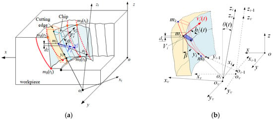
Figure 3.
Instantaneous cutting boundary of cutting edge and instantaneous cutting volume. (a) Instantaneous cutting boundary of cutting edge; (b) instantaneous cutting volume.
According to Figure 3, the upper boundary (mk) and lower boundary (m0) of the cutting edge, which participate in cutting instantaneously under the influence of milling vibration and cutter tooth error, can be written as
where θi(t) is the instantaneous position angle of the tool tip. θst is the initial cutting angle of the cutter teeth. θwt is the initial cutting angle of the cutter teeth, which is 3π/2. θet is the position angle when the cutter tooth completely cuts out the workpiece. θp is the position angle when the cutting edge initially reaches the cutting depth.
The instantaneous cutting-layer parameters and cutting volume per unit time of micro-elements milled on the cutting edge can be expressed as
where fzi is the feed per tooth of the ith cutter tooth. vci(t) is the component of the instantaneous velocity of the synthetic cutting motion of any point of the ith cutter tooth relative to the workpiece, considering the vibration velocity in the direction of the main motion velocity of the milling cutter.
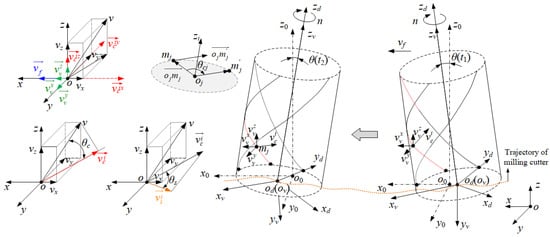
Figure 4.
Velocity decomposition of synthetic cutting motion of cutting edge feature points.
In Figure 4, vcix is the component of vci on the x-axis. vciy is the component of vci on the y-axis. vciz is the component of vci on the z-axis. vvx is the component of the vibration velocity on the x-axis. vvy is the component of the vibration velocity on the y-axis. vvz is the component of the vibration velocity on the z-axis.
From Equations (1)–(9) and Figure 4, the instantaneous velocity of the synthetic cutting motion and instantaneous cutting velocity of the milling micro-element can be solved as
where θc(t) is the angle between v(t) and vci(t) in the workpiece coordinate system. The direction of vci(t) is consistent with the vector direction. The coordinate of and in the workpiece coordinate system were obtained using Equations (32)–(33).
Using Equations (27)–(33), the distribution functions of the instantaneous cutting-force energy consumption and instantaneous shear energy consumption of the milling micro-elements were expressed as
where
and where kt is the correction factor of tangential force, and its value range is 1.17~1.68, when the end mill is cutting titanium alloy. κc(z,t) is the unit cutting force. vsi(t) is the shear direction speed at the selected point of the ith cutter tooth. τi(z,t) is the shear stress at any point of the ith cutter tooth. θs is the shear angle. μ is the friction coefficient, which can be obtained from the literature [23]. a is the lattice constant (2.9506 × 10⁻¹⁰ m). h is the Planck constant (h = 6.62607015 × 10⁻³⁴ J·s). k is the Boltzmann constant (k = 1.380649 × 10⁻²³ J/K). υ is the frequency of atomic forced vibration. FN is the normal stress at the characteristic point of the cutting edge.
Thus, the instantaneous shear energy efficiency and specific cutting energy of the milling micro-element can be expressed as
From Equations (39)–(41), due to the influence of milling vibration, cutter tooth error and other factors, the cutting attitude angle of the milling cutter and the cutting trajectory of the cutter tooth were in an unstable state. This unstable state caused the instantaneous contact relationship between the milling micro-element on the cutting edge of the cutter tooth and the workpiece to change frequently. The change resulted in the instantaneous cutting-force energy efficiency and specific cutting energy of the milling micro-element changing along the cutting edge and changing with time. Additionally, its distribution had dynamic characteristics. It was necessary to further study the distribution of the instantaneous cutting energy efficiency of the cutter tooth.
4. Distribution of Instantaneous Cutting Energy Efficiency of Cutter Teeth under Vibration
In order to solve the instantaneous energy efficiency of the cutting edge under vibration, the cutting experiment of the end-milling cutter was carried out via the VDL-1000E three-axis milling center using the integral carbide end-milling cutter and cutting conditions for titanium alloy provided by the enterprise. Among them, the cutting method was dry cutting. The cutting stroke of the milling cutter was 6 m, and we carried out repeated feeding 20 times. The Integral carbide end-milling cutter was MC122-20.0A5B-WJ30TF, produced by Walter. Its diameter was 20 mm, the helix angle was 50°, and the number of teeth was five. Before the milling experiment, a Zoller 1610A tool setting instrument was used to measure the axial length and turning radius of each cutter tooth of the milling cutter, obtaining the axial error and radial error. The milling parameters and cutter tooth errors are shown in Table 1.

Table 1.
Milling scheme and cutter tooth error distribution.
Based on the experimental scheme in Table 1, the Kistler three-way rotary dynamometer was used to detect the cutting-force signals of the milling cutter with regard to feed speed, cutting width and cutting depth during the cutting process. The milling vibration acceleration signal was obtained using a DH5922 instantaneous signal test and analysis system and an acceleration sensor, as shown in Figure 5.
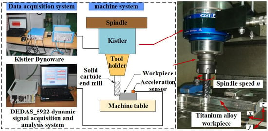
Figure 5.
Experiment on milling vibration and cutting force.
Using the specific parameters in Table 1 and the experimental setup in Figure 5, the milling vibration acceleration signals were acquired by using the acceleration sensor. The results showed that the milling vibration acceleration signal of the last feed was relatively smooth, so the milling vibration acceleration signal of the last feed was selected, as shown in Figure 6.
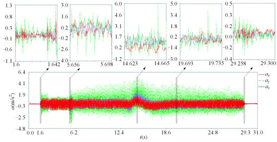
Figure 6.
Milling vibration acceleration signal.
Combined with Table 1 and Figure 6, according to Equations (10) and (11), the trajectory and attitude angle of the milling cutter were implemented by compiling MATLAB software. The 470th cycle and 471st cycle in the cutting process were selected to calculate the cutter tip trajectory and attitude angle. The results are shown in Figure 7. Among them, in order to compare the differences in the posture of the cutter tip in adjacent cycles, the 470th cycle and 471st cycle were taken as examples to solve the posture. This was because the periodic changes in the milling vibration acceleration signal in the 470th and 471st cycles were relatively smooth and steady. Therefore, these two cycles were taken as representatives of the relatively stable vibration signal during the cutting process of the milling cutter.
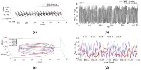
Figure 7.
Trajectory and attitude angle of milling cutter and cutter tip. (a) Milling cutter trajectory; (b) milling cutter attitude angle; (c) cutter tip trajectory; (d) cutter tip attitude angle.
From Figure 7, the instantaneous cutting posture of the milling cutter and its cutter teeth were changed regarding the milling vibration and the cutter tooth error. The displacement increment of different degrees of each cutter tooth was caused by the milling vibration, which led to obviously different instantaneous cutting behavior variation.
We used the milling cutter offset caused by the vibration in Figure 6, and the instantaneous cutting boundary of the cutting edge in the 470th cycle according to Equations (22)–(26) is shown in Figure 8.
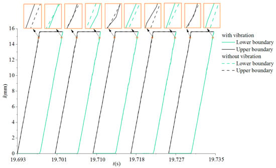
Figure 8.
Instantaneous cutting boundary of the cutting edge.
Using Equations (29)–(33) and (36)–(38), the instantaneous cutting velocity and direction velocity of any point of the cutting edge involved in cutting was obtained. The selected point mj (5.6, 8.3, 5) in the cutter tooth coordinate system is as an example. This was because the point mj took the longest time to participate in cutting relative to the other positions of the cutting edge during the time from the cutter tooth cutting in to cutting out. This could more completely reflect the changing of parameters such as instantaneous cutting velocity, shear direction velocity, etc. in a cycle. Therefore, point mj was selected as an example to calculate the instantaneous cutting velocity and shear direction velocity, and the results are shown in Figure 9.
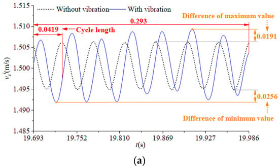
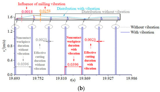
Figure 9.
Instantaneous cutting velocity and shear direction velocity of selected cutting edge point. (a) Instantaneous cutting velocity; (b) shear direction velocity.
It can be seen from Figure 9 that the instantaneous cutting speed and shear direction speed at any point on the cutter teeth had obvious changes because of the variation in the trajectory and attitude angle of the milling cutter and its cutter teeth under milling vibration.
According Equations (27) and (28), the instantaneous cutting volume of the selected cutting edge point is shown in Figure 10.
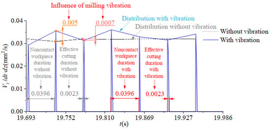
Figure 10.
Instantaneous cutting volume of the selected cutting edge point.
According to the above solution results, the cutting process of the milling cutter was unstable. Among them, the instantaneous cutting boundary of the cutter teeth and the parameters of the instantaneous cutting layer of the milling cutter were constantly changing. This changing caused variation in the instantaneous cutting-force energy consumption and the shear energy consumption of the cutter teeth, which led to inconsistent variation in the shear energy efficiency and the specific cutting energy distribution of the cutter teeth along the cutting edge.
In order to obtain the shear stress of each point of the cutting edge, finite element simulation was used. The machining (cutting) module of the finite element simulation software Deform-3D was using to simulate the cutting process of the end-milling cutter, as shown in Figure 11. UG was used to build the milling cutter and workpiece models and import them into the simulation module. The Johnson–Cook constitutive parameters of Ti-6Al-4V titanium alloy material are shown in Table 2.
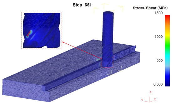
Figure 11.
Simulation of cutting process of the helical end mill.

Table 2.
Parameters of J-C constitutive of Ti-6Al-4V titanium alloy.
In Table 2, σs, sc, se, sp and Ts are the yielding-stress envelope, strain-hardening constant, strain-hardening exponent, strain-rate-hardening parameter and temperature strain-rate sensitivity, respectively.
The boundary conditions of the simulation are shown in Table 3.

Table 3.
Boundary conditions of finite element simulation.
The number of meshes divided by the cutter teeth in the simulation process was 590,000, and minimum size of the grid was 0.3 mm. In order to make the simulation results more accurate, when the workpiece was meshed with absolute size, the convergence effect was best when the step distance did not exceed 1/3 of the minimum element size of the workpiece grid element.
According to the simulation results in Figure 11, the shear stress at each point of the cutting edge was obtained. The shearing and tangential forces were calculated. The distribution of the tangential-force energy consumption along the cutting edge direction was obtained using Equation (34). The distribution of the shearing-force energy consumption along the cutting edge direction was obtained using Equation (35). According to Figure 11 and Equations (34) and (35), the shear energy consumption and the tangential force energy consumption were solved. Using Equations (39)–(41), the shear energy efficiency and specific cutting energy of the cutting edge were calculated. We selected the same contact angle in different cycles to study the variation in its instantaneous distribution. The contact angles of the cutter tip were 162°, 165.6°, 169.2°, 172.8°, 176.4°, 180° and 183.6°. We took the five cutter teeth in the 470th cycle as an example when the contact angle was 172.8°. The distribution of the cutter teeth’s instantaneous shear energy efficiency, tangential-force specific energy and specific shear energy along the cutting edge are shown in Figure 12 and Figure 13.
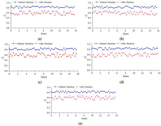
Figure 12.
The distribution of instantaneous shear energy efficiency along cutting edge. (a) Tooth 1; (b) Tooth 2; (c) Tooth 3; (d) Tooth 4; (e) Tooth 5.
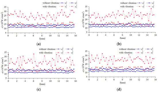
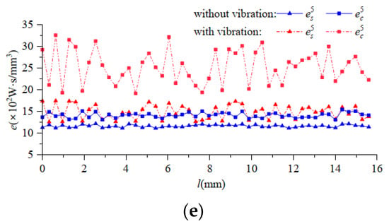
Figure 13.
The distribution of instantaneous specific cutting energy along cutting edge. (a) Tooth 1; (b) Tooth 2; (c) Tooth 3; (d) Tooth 4; (e) Tooth 5.
In the above figures, l is the unfolded length of the helical cutting edge of the cutter tooth.
It can be seen from Figure 12 and Figure 13 that the instantaneous energy-efficiency distribution and specific cutting energy distribution of the cutting edge without vibration were unstable. This was because in the Deform simulation process, the thermal-stress-coupling field of the milling cutter was constantly changing, which led to the differences in the force at different positions on the cutting edge. This made the volume of material removed different. Therefore, the value of the instantaneous cutting-force energy efficiency along the different heights of same cutting edge without vibration did not remain unchanged. Compared with the instantaneous cutting-force energy=-efficiency distribution of the cutting edge without vibration, milling vibration made the instantaneous shear energy efficiency and specific cutting energy of the cutting edge show more complex spatial distribution.
5. Identification Method of Variation in Milling Cutter’s Cutting Energy-Efficiency Distribution under Vibration
In order to reveal the dynamic of the instantaneous energy efficiency of the milling cutter under vibration, the cutting edge shear energy efficiency with vibration and without vibration were solved using Equation (39), as shown in Figure 14.
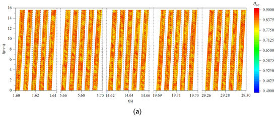
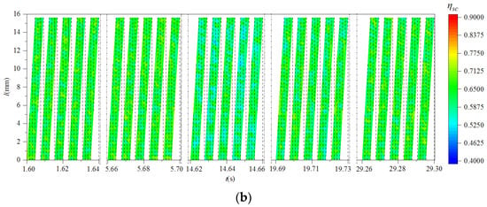
Figure 14.
The distributive variation in instantaneous shear energy efficiency of cutting edge with and without vibration. (a) Without milling vibration; (b) with milling vibration.
It can be seen from Figure 14 that at the same time, the distribution of shear energy efficiency along the cutting edge was not consistent. Compared with different times, the shear energy-efficiency values of multiple cutter teeth were obviously different. At the same time, the shear energy efficiency of the cutting edge without milling vibration was significantly higher than that under milling vibration. This means that the milling vibration consumes part of the energy originally used to remove materials during the milling process, thus reducing the shear energy efficiency.
Using Equations (40) and (41), the cutting edge specific shear energy and specific tangential-force energy were calculated, as shown in Figure 15 and Figure 16.
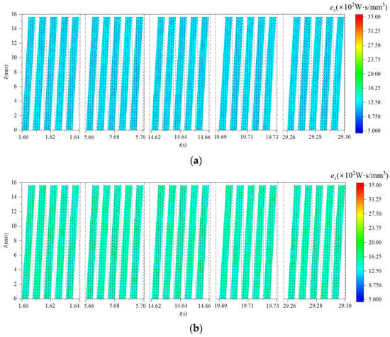
Figure 15.
The distributive variation in instantaneous specific shear energy of cutting edge with and without vibration. (a) Without milling vibration; (b) with milling vibration.
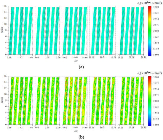
Figure 16.
The distributive variation in instantaneous specific tangential-force energy of cutting edge with and without vibration. (a) Without milling vibration; (b) with milling vibration.
According to Figure 15, the distribution of the specific shear energy of the cutting edges with different cutter teeth was obviously different. At the same time, the specific shear energy of the cutting edge with milling vibration was higher than that without milling vibration. This means that in the process of milling, the existence of milling vibration reduced the useful energy consumption, causing a reduction in the volume of material removed, ultimately leading to an increase in the specific shear energy.
It can be seen from Figure 16 that milling vibration reduced the specific tangential-force energy of the cutting edge and increased the complexity of its distribution. Compared with Figure 15 and Figure 16, the specific tangential-force energy was significantly higher than the specific shear energy. This was because the energy consumption of tangential force also included the energy consumption of cutter tooth friction and heat loss. Therefore, if the same workpiece material volume was removed in a unit of time, the energy consumption of tangential force would be greater than that of shearing.
According to Equations (17) and (19), the cutting energy efficiency of the milling cutter was obtained, as shown in Figure 17.
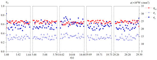
Figure 17.
Cutting energy efficiency of milling cutter.
We can see from Figure 17 that, influenced by milling vibration, the cutting energy efficiency of the milling cutter was variable during the process of cutting in and out of the workpiece. The overall level of specific tangential-force energy of the milling cutter was higher than the specific shear energy, but the effective utilization of energy was reflected in the material removal volume. Compared with the energy consumption of the tangential force, the energy consumption of shearing could directly affect the volume of removed materials. Therefore, the specific shear energy was more suitable for evaluating the cutting performance of milling cutter than the specific tangential-force energy.
According to the above model and results, the identification method of distributive variation in instantaneous cutting energy efficiency under milling vibration was proposed, as shown in Figure 18.
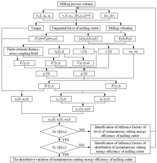
Figure 18.
Modeling and distribution identification of instantaneous cutting energy efficiency of milling cutter under vibration.
The method used the relationship between the instantaneous cutting behavior of the cutter teeth under milling vibration and cutter tooth error, obtaining the finite element thermal-stress-coupling field of any position on the effective cutting edge of the milling cutter. The distributions of the instantaneous tangential force and shearing force along the cutting edge were quantitatively characterized. Additionally, changes in the instantaneous tangential-force energy consumption and shear energy consumption of the milling cutter were further revealed. The distribution and its variation in the milling cutter’s energy efficiency and specific cutting energy along the cutting edge were revealed using the calculation method of the milling cutter’s instantaneous cutting energy efficiency. The method was verified using the relative and grey relative correlation degrees, as shown in Figure 18.
When the type of milling cutter and the cutting parameters changed, according to the above method, the structural parameters, the pose parameters of the milling cutter and cutter teeth, and the cutting parameters were changed accordingly. The thermal–mechanical-coupling field model in the milling cutter’s cutting process was reconstructed. The instantaneous cutting force and shearing force of the milling cutter teeth were obtained using the calculation methods of an instantaneous cutting boundary, cutting-layer parameters, cutting velocity and shear direction velocity of the cutter teeth. The instantaneous tangential-force energy consumption and shearing energy consumption of the milling cutter were solved. The instantaneous shearing energy efficiency and specific cutting energy of the milling cutter under different technological conditions could be obtained.
6. Response Analysis and Experimental Verification of Milling Cutter’s Cutting Energy Efficiency
6.1. Response of Instantaneous Cutting Energy Efficiency of Milling Cutter
To verify the effectiveness of the identification method, the structure parameters, initial process design posture, and cutting efficiency of the milling cutter in Table 1 were kept unchanged by changing the spindle speed, feed rate per tooth and cutter tooth error. The specific scheme is shown in Table 4.

Table 4.
Milling scheme 2 and its cutter tooth error distribution.
According the Table 4, the milling vibration acceleration signal of scheme 2 was obtained, as shown in Figure 19.
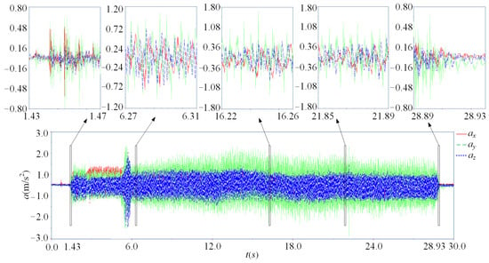
Figure 19.
The milling vibration acceleration signal (scheme 2).
Using Equations (39)–(41), the shear energy efficiency, specific shear energy and the specific tangential-force energy of scheme 2 were calculated, as shown in Figure 20 and Figure 21.
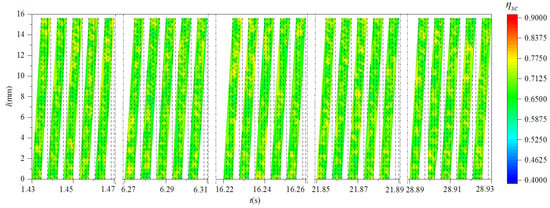
Figure 20.
The distributive variation in shear energy efficiency of cutter teeth (scheme 2).
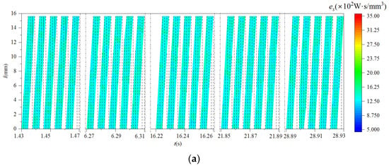
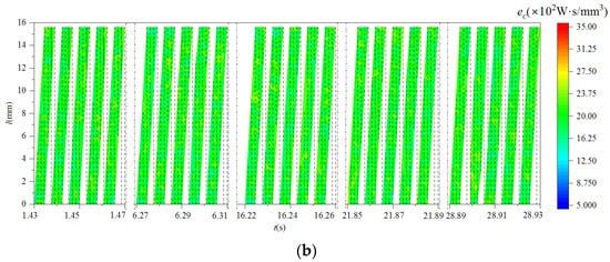
Figure 21.
The distribution of specific cutting energy of cutter teeth (scheme 2). (a) The distribution of specific shear energy of cutter teeth; (b) the distribution of specific tangential-force energy of cutter tooth.
It can be seen from Figure 17 and Figure 22 that the shear energy efficiency of the milling cutter in scheme 2 was improved and had good stability after changing the spindle speed and cutter tooth error. Compared with scheme 1, the specific shear energy and specific tangential-force energy of scheme 2 were both reduced. This represents that the cutting energy required for scheme 2 to remove the workpiece material per unit volume was less than that required for scheme 1. The above analysis further indicated that reducing the spindle speed and changing the cutter tooth error distribution could improve the level of the milling cutter’s cutting energy efficiency.
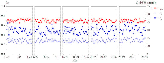
Figure 22.
Variation in instantaneous cutting energy efficiency of milling cutter (scheme 2).
6.2. Experimental Verification of Instantaneous Cutting Energy Efficiency of Milling Cutter
In order to verify the correctness of the calculation of the instantaneous tangential-force energy efficiency of the milling cutter under vibration, the calculation results and the measured results of the tangential-force energy efficiency were compared. Among them, the input energy of the milling vibration of the calculation result and measured result of the milling cutter input energy were both measured via experiments. According to Figure 6 and Figure 19 and Equation (42), the input energy of milling cutter vibration was obtained, as shown in Figure 23.

Figure 23.
Input energy of milling vibration of scheme 1 and scheme 2. (a) scheme 1; (b) scheme 2.
Comparing (a) and (b) in Figure 23, it can be seen that reducing the spindle speed, increasing the feed rate per tooth, and changing the distribution of the cutter tooth error resulted in changes in the vibration acceleration signal. This caused significant differences in the vibration input energy of the milling cutter. Among them, the vibration input energy of the milling cutter in scheme 1 was concentrated in the middle cutting section, which indicated that the input energy of the milling cutter fluctuated in the middle cutting section. The input energy of milling vibration in scheme 2 was relatively high during the cut-in section, representing that the input energy of the milling cutter was relatively unstable during the cut-in section.
Using Equation (17), the solved results and measured results of the tangential-force energy efficiency of scheme 1 and scheme 2 were obtained. We took the 470th cycle results as an example, as shown in Figure 24.

Figure 24.
The solved and measured results of tangential-force energy efficiency of milling cutter. (a) scheme 1; (b) scheme 2.
As seen from Figure 24, the distribution curve of the tangential-force energy efficiency of the milling cutter was close to the measured result. The relative error range between the tangential-force energy-efficiency calculation and the measured results in scheme 1 was 5.8%~18.4%. The relative error range between the tangential-force energy-efficiency calculation and the measured results in scheme 2 was 5.1%~19.3%. In order to further verify the accuracy of the distribution of the milling cutter tangential-force energy-efficiency calculation results, the improved grey relative correlation analysis algorithm was used. The tangential-force energy-efficiency solution result was the comparison sequence, and the measured tangential-force energy efficiency result was the reference sequence. The correlation degree of scheme 1 was 0.87, and the correlation degree of scheme 2 was 0.89. The above results showed that the overall level and variation in the calculation results of milling cutter tangential-force energy efficiency were in good agreement with the measured results.
In order to verify the correctness of the calculation model of the instantaneous cutting-force specific energy of the milling cutter, the experimental results and calculation results of the tangential-force specific energy were compared. According to the machined surface topography measured via white-light interferometer (model: Talysurf CCI MP, produced by Taylor Hobson), the measured results of the instantaneous cutting volume of the milling cutter were obtained, as shown in Figure 25 and Equations (43)–(46).
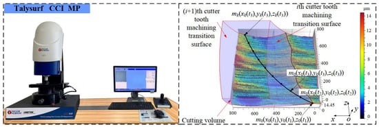
Figure 25.
Experimental solution of cutting volume.
Using Figure 25, the cutting volume was calculated using the structure of the milling cutter and the instantaneous posture of the cutter teeth, as shown in Equations (43)–(46).
According to Equations (43)–(46), the measured results of the instantaneous cutting volume of the milling cutter were obtained. Combined with the measured results of tangential force, the measured results of specific tangential-force energy were calculated. We compared them with the calculation results of the specific tangential-force energy, as shown in Figure 26. When the contact angle of the cutter tip of each cutter tooth was 172.8°, the instantaneous cutting boundary range of the cutter tooth was close to the maximum and the energy consumption of tangential force was high. Therefore, the time corresponding to 172.8° was selected as the reference value for calculating the cutting-force specific energy in different cutting cycles.

Figure 26.
The solved and measured results of specific tangential-force energy of milling cutter. (a) scheme 1; (b) scheme 2.
It can be seen from Figure 26 that the instantaneous specific tangential force of the milling cutter changed significantly after changing the spindle speed and cutter tooth error distribution. This indicated that the calculation model of the instantaneous tangential-force energy of the milling cutter was sensitive. At the same time, it can be seen that the overall level of the solution results of scheme 1 and scheme 2 was greater than the measured results. In the process of calculating the instantaneous specific tangential-force energy of milling cutter, the value of the unit cutting force was too large, which was the main reason for the above differences.
In order to verify the correctness of the calculation of the milling cutter’s specific tangential-force energy, the relative error between the measured and the calculated results of the milling cutter’s instantaneous specific tangential-force energy in Figure 25 was calculated. The relative error range of scheme 1 was 12.2%~19.3%. The relative error range in scheme 2 was 10.9%~19.0%. In order to further verify the accuracy of specific tangential-force energy distribution, the improved grey relative correlation analysis algorithm was used. The specific tangential-force energy solution result was the comparison sequence and the specific tangential-force energy measured result was the reference sequence. The correlation degree of scheme 1 was 0.84, and the correlation degree of scheme 2 was 0.81. The above results showed that the calculation results of the instantaneous specific tangential-force energy of the milling cutter were highly similar to the measured results. This indicated that the mapping relationship between the cutting energy consumption and the material removal rate can be identified using the instantaneous specific tangential-force energy model of the milling cutter. It would achieve the purpose of evaluating the energy-efficiency level of the milling cutter.
7. Conclusions
- (1)
- A correlation model between the instantaneous cutting energy efficiency of the milling cutter and the instantaneous specific cutting energy distribution of the cutter tooth’s cutting edge was constructed. This achieved effective communication between the instantaneous cutting energy consumption, the instantaneous cutting energy efficiency, and the workpiece material removal rate of the cutter tooth and milling cutter. The key control variables of the dynamic relationship between the instantaneous cutting energy transfer and conversion of the milling cutter were revealed.
- (2)
- The results of the cutting energy-efficiency distribution of the cutter teeth showed that milling vibration and cutter tooth error changed the instantaneous cutting-layer thickness, instantaneous cutting volume, and instantaneous cutting boundary of the cutter teeth. Irregular variation in the above parameters caused variability of the instantaneous cutting energy consumption on the cutting edge. The difference between the spatial distribution of the instantaneous cutting-force energy efficiency and specific cutting energy along different cutting edges were revealed.
- (3)
- The identification method of the distribution of the cutting energy efficiency of the milling cutter under vibration was proposed. Using the model of instantaneous cutting energy efficiency of each point of the cutter teeth, the variation in the instantaneous cutting energy efficiency at any point on the cutting edge could be obtained. The results showed that the instantaneous cutting energy efficiency of the milling cutter could be improved by adjusting the initial process design variables. It is believed that this identification method for the distribution of the cutting energy efficiency of the milling cutter could provide a basis for the design of a high-energy-efficiency milling cutter and its technological scheme.
- (4)
- A calculation method for the cutting volume based on the machined surface topography was proposed. This method can obtain the instantaneous cutting volume of the milling cutter at a selected time using the machined surface topography and the cutting posture of the milling cutter and its cutter teeth. The results showed that the relative error of the curve level between the calculation results and the measured results of the milling cutter’s cutting energy efficiency was less than 20%. Additionally, the correlation degree was greater than 0.80, indicating that the above models and methods could be used to evaluate the milling cutter’s energy-efficiency level. However, the influence of milling cutter wear on milling vibration and cutting force was ignored in this paper. Therefore, it is necessary to conduct further research and verification combined with friction and wear experiments.
Author Contributions
Conceptualization, B.J. and L.F.; methodology, B.J. and L.F.; software, L.F. and Y.S.; validation, P.Z. and B.W.; investigation, L.F. and B.W.; data curation, L.F. and Y.S.; writing—original draft preparation, L.F.; writing—review and editing, L.F. and P.Z.; supervision, B.J. and P.Z.; project administration, B.J.; funding acquisition, B.J. All authors have read and agreed to the published version of the manuscript.
Funding
This research was funded by the National Natural Science Foundation of China (51875145), the Natural Science Foundation of Heilongjiang Province, China (ZD2020E008) and the National Natural Science Foundation of China (52105440).
Institutional Review Board Statement
Not applicable.
Informed Consent Statement
Not applicable.
Data Availability Statement
No data were reported for this study, so we have chosen to exclude this section.
Conflicts of Interest
The authors declare no conflict of interest.
Nomenclature
| Number | Professional Terminology | Meaning |
| 1 | Instantaneous cutting energy efficiency | This includes instantaneous cutting-force energy efficiency and specific cutting energy. |
| 2 | Instantaneous cutting-force energy efficiency | This includes instantaneous tangential-force energy efficiency and shear energy efficiency. |
| 3 | Specific cutting energy | This includes specific tangential-force energy and specific shear energy. |
| 4 | Tangential-force energy efficiency | The proportion of the energy consumption of the tangential force in the input energy of the milling cutter. |
| 5 | Shear energy efficiency | The proportion of energy consumption of shearing force in the tangential force. |
| 6 | Specific tangential-force energy | The tangential-force energy consumed by removing the workpiece material per unit volume. |
| 7 | Specific shearing-force energy | The shear energy consumed by removing the workpiece material per unit volume. |
| 8 | Instantaneous tangential-force energy consumption | The energy consumed by the tangential force to perform work at a certain time. |
| 9 | Instantaneous shearing-force energy consumption | The energy consumed by the shearing force to perform work at a certain time. |
| 10 | Intermittent cutting process | The cutting process in which the cutter teeth contact the workpiece intermittently due to the replacement of multiple gears of the milling cutter. |
| 11 | Cutter tooth error | This refers to the manufacturing error generated during the tool manufacturing process, including the axial error and radial error of the cutter teeth. |
| 12 | Distribution functions | The function of the change in a dependent variable with time along a specified direction. |
References
- Tamura, S.; Matsumura, T. Cutting Force Simulation in Milling with Multi-edges Cutter. AIP Conf. Proc. 2017, 1896, 090010. [Google Scholar]
- Sun, T.; Qin, L.F.; Fu, Y.C.; Liu, C.Q.; Shi, R.L. Mathematical modeling of cutting layer geometry and cutting force in orthogonal turn-milling. J. Mater. Process. Technol. 2021, 290, 116992. [Google Scholar] [CrossRef]
- Osman, K.A.; Ylmaz, V.; Unver, H.O.; Seker, U.; Kilic, S.E. Slot milling of titanium alloy with hexagonal boron nitride and minimum quantity lubrication and multi-objective process optimization for energy efficiency. J. Clean. Prod. 2020, 258, 120739. [Google Scholar] [CrossRef]
- Asrai, R.I.; Newman, S.T.; Nassehi, A. A mechanistic model of energy consumption in milling. Int. J. Prod. Res. 2018, 56, 642–659. [Google Scholar] [CrossRef]
- Zhang, T.; Liu, Z.Q.; Sun, X.D.; Xu, J.X.; Dong, L.L.; Zhu, G.L. Investigation on specific milling energy and energy efficiency in high-speed milling based on energy flow theory. Energy 2020, 192, 116596. [Google Scholar] [CrossRef]
- Hu, Z.H.; Qin, C.J.; Shi, Z.W.; Tang, Y.R.; Zhang, X.D.; Zou, Y.M. An effective thread milling force prediction model considering instantaneous cutting thickness based on the cylindrical thread milling simplified to side milling process. Int. J. Adv. Manuf. Technol. 2020, 110, 1275–1283. [Google Scholar] [CrossRef]
- Mou, W.P.; Zhu, S.W.; Zhu, M.H.; Han, L.; Jiang, L. A Prediction Model of Cutting Force about Ball End Milling for Sculptured Surface. Math. Probl. Eng. 2020, 2020, 8065396. [Google Scholar] [CrossRef]
- Ozturk, B.; Kara, F. Calculation and Estimation of Surface Roughness and Energy Consumption in Milling of 6061 Alloy. Adv. Mater. Sci. Eng. 2020, 2020, 5687951. [Google Scholar] [CrossRef]
- Jiang, B.; Li, H.Y.; Fan, L.L.; Zhao, P.Y. A Model for Energy Consumption of Main Cutting Force of High Energy Efficiency Milling Cutter under Vibration. Appl. Sci.-Basel 2022, 12, 1531. [Google Scholar] [CrossRef]
- Ducroux, E.; Fromentin, G.; Viprey, F.; Prat, D.; D’Acunto, A. New mechanistic cutting force model for milling additive manufactured Inconel 718 considering effects of tool wear evolution and actual tool geometry. J. Manuf. Process. 2021, 64, 67–80. [Google Scholar] [CrossRef]
- Luan, X.N.; Zhang, S.; Li, G. Modified power prediction model based on infinitesimal cutting force during face milling process. Int. J. Precis. Eng. Manuf.-Green Technol. 2018, 5, 71–80. [Google Scholar] [CrossRef]
- Yuan, J.J.; Shao, H.; Cai, Y.; Shi, X.H. Energy efficiency state identification of milling processing based on EEMD-PCA-ICA. Measurement 2021, 174, 109014. [Google Scholar] [CrossRef]
- Cai, Y.; Shi, X.H.; Shao, H.; Yuan, J.J. Energy Efficiency State Identification Based on Continuous Wavelet Transform—Fast Independent Component Analysis. J. Manuf. Sci. Eng.-Trans. ASME 2018, 141, 021012. [Google Scholar] [CrossRef]
- Jamil, M.; Zhao, W.; He, N.; Gupta, M.K.; Sarikaya, M.; Khan, A.M.; Sanjay, M.R.; Siengchin, S.; Pimenov, D.Y. Sustainable milling of Ti–6Al–4V: A trade-off between energy efficiency, carbon emissions and machining characteristics under MQL and cryogenic environment. J. Clean. Prod. 2021, 281, 125374. [Google Scholar] [CrossRef]
- Zhou, M.H.; Chen, Y.H.; Zhang, G.Q. Force Prediction and Cutting-Parameter Optimization in Micro-Milling Al7075-T6 Based on Response Surface Method. Micromachines 2020, 11, 766. [Google Scholar] [CrossRef]
- Zhang, X.W.; Yu, T.B.; Dai, Y.X.; Qu, S.; Zhao, J. Energy consumption considering tool wear and optimization of cutting parameters in micro milling process. Int. J. Mech. Sci. 2020, 178, 105628. [Google Scholar] [CrossRef]
- Plodzien, M.; Zylka, L.; Sulkowicz, P.; Zak, K.; Wojciechowski, S. High-Performance Face Milling of 42CrMo4 Steel: Influence of Entering Angle on the Measured Surface Roughness, Cutting Force and Vibration Amplitude. Materials 2021, 14, 2196. [Google Scholar] [CrossRef]
- Shin, S.J.; Woo, J.; Rachuri, S. Energy efficiency of milling machining: Component modeling and online optimization of cutting parameters. J. Clean. Prod. 2017, 161, 12–29. [Google Scholar] [CrossRef]
- Zhu, Z.R.; Peng, F.Y.; Tang, X.W.; Yan, R.; Li, Z.P.; Chen, C.; Sun, H. Specific cutting energy index (SCEI)-based process signature for high-performance milling of hardened steel. Int. J. Adv. Manuf. Technol. 2019, 103, 1–13. [Google Scholar] [CrossRef]
- Kundrak, J.; Karpuschewski, B.; Palmai, Z.; Felho, C.; Makkai, T.; Borysenko, D. The energetic characteristics of milling with changing cross-section in the definition of specific cutting force by FEM method. CIRP J. Manuf. Sci. Technol. 2021, 32, 61–69. [Google Scholar] [CrossRef]
- He, Y.; Wang, L.X.; Wang, Y.L.; Li, Y.F.; Wang, S.L.; Wang, Y.; Liu, C.; Hao, C.P. An analytical model for predicting specific cutting energy in whirling milling process. J. Clean. Prod. 2019, 240, 118181. [Google Scholar] [CrossRef]
- Liu, Z.Y.; Sealy, M.P.; Li, W.; Zhang, D.; Fang, X.Y.; Guo, Y.B.; Liu, Z.Q. Energy consumption characteristics in finish hard milling. J. Manuf. Process. 2018, 35, 500–507. [Google Scholar] [CrossRef]
- Jiang, B.; Li, W.H.; Zhao, P.Y.; Fan, L.L.; Sun, M. Identification for friction behavior variation of the minor flank of square shoulder milling cutter under vibration. Appl. Sci.-Basel 2022, 12, 4038. [Google Scholar] [CrossRef]
Publisher’s Note: MDPI stays neutral with regard to jurisdictional claims in published maps and institutional affiliations. |
© 2022 by the authors. Licensee MDPI, Basel, Switzerland. This article is an open access article distributed under the terms and conditions of the Creative Commons Attribution (CC BY) license (https://creativecommons.org/licenses/by/4.0/).