Article

DLP Light-Curing 3D Printing Combustible Lighting Shell and Performance Study

School of Equipment Engineering, Shenyang Ligong University, Shenyang 110159, China
*
Author to whom correspondence should be addressed.
Appl. Sci. 2022, 12(20), 10401; https://doi.org/10.3390/app122010401
Submission received: 13 September 2022 / Revised: 10 October 2022 / Accepted: 13 October 2022 / Published: 15 October 2022

Abstract

:
In order to further improve the luminous intensity of illuminating flares, the technique of 3D printing of the combustible shell of the illuminating flare using DLP light-curing was proposed, and the combustion spectrum of the combustible shell was made consistent with the combustion spectrum of the illuminating agent. A combustible illuminating candle shell slurry formulation was designed, with light-curing resin, magnesium powder, and sodium nitrate as the main components, and was printed and molded by DLP light-curing 3D printing technology to test its luminescence properties, mechanical properties, compatibility, and moisture absorption. The results show that the optimal formulation mass fraction of energy-containing slurry for the 3D printing of the combustible lighting candle shell is 50% for light-curing resin, 41% for sodium nitrate (NaNO3), and 9% for magnesium powder (Mg). The mechanical properties of the shell are good, with tensile strength up to 9.82 MPa and compressive strength of 102.86 MPa, and the compatibility of the components of the formulation is good, with stable combustion, and can provide 4.73% of light intensity for the lighting candle.

1. Introduction

When an illuminating flare [1,2] is launched above a target, the illuminating candle system is ejected. The illuminant in the illuminating candle system burns and emits strong light, providing a light source for night operations. At present, this is still one of the most indispensable types of special ammunition in modern warfare. The shell of the illuminating candle is composed of steel 20 [3], and the shell of the illuminating candle accounts for one third of the total mass of the illuminating candle system. The high mass ratio limits the charge quality of the illuminant in the system, thus affecting the overall luminous intensity. The metal shell will not provide luminous intensity for the illuminating candle when the system is working. With the development of science and technology, military warfare has put forward higher requirements for the luminous performance of illuminating candles. There are two main methods to enhance the luminous performance of illuminating candles: (1) improve the formula and proportion of the illuminant charge and improve the light quantity per unit mass; (2) on the premise of ensuring the same amount of illuminant, reduce the quality of the illuminating candle shell and increase the time for which the illuminating candle remains in the air [4]. In order to reduce the weight of the shell, a combustible shell [5] can be burned together with the illuminant at the expense of some mechanical strength, which can enhance the overall luminous performance. At the same time, it can disappear automatically after combustion, without shell withdrawal and waste shell accumulation [6], providing a new idea for enhancing the luminous performance of the illuminating candle. At present, there is no research on combustible shells for illuminating candles.
Commonly used illuminating candle shells have two types of structures: integral and non-integral. The integral illuminating candle shell is formed by stamping and cold drawing, and is connected by edging. It has the advantage of high strength. The non-integral illuminating candle shell is welded by two parts: a cylinder and a circular plate. Both integral and non-integral structures need to use a mold with fixed size, and the processing and forming method is more complex than the 3D printing and forming method. In particular, 3D printing is stacked layer-by-layer by extrusion [7], melt deposition [8], light-curing treatment [9], jetting [10], etc., which can enable the shell’s rapid prototyping at one time. The printing structure is freer and the process is controllable. Since traditional technology requires the establishment of production lines, 3D printing is different from the traditional process. It not only does not require molds, but greatly simplifies the production and manufacturing process, which can effectively reduce the production costs such as human and material resources. In addition, when the traditional process is used to manufacture parts, it requires multiple pieces of equipment or even multiple production lines to cooperate. Therefore, compared with the traditional process, 3D printing also improves production efficiency. This technology is widely used in aerospace, casting, biopharmaceutical, and food processing fields [11]. In the field of manufacturing energetic materials, 3D printing technology is commonly used for the manufacturing and molding of propellant powder [12,13,14] and propellants [15]. Wang Dunju et al. [16] designed a CL-20-based ink with uniform dispersion and proper rheology, which will not cause caking or nozzle blockage, and the printed finished product has a high burning speed. Therefore, it is feasible to print an energetic slurry by direct writing 3D, but extrusion will increase the local pressure of grains, which is very dangerous to some extent.
Compared with extrusion, melting, and other methods, UV curing 3D printing technology can better ensure the safety of printing energetic materials. It also has the characteristics of high production efficiency, less pollution, energy savings, and excellent performance of cured products [17,18]. In order to improve the complex forming process of a uniquely shaped charge, Chen Yongjin [19] printed a uniquely shaped energetic charge with light-curing technology, which provides stable combustion and a fast burning speed. Manman Li et al. [12] prepared a propellant composed of APNIMMO and CL-20. Through UV light-curing 3D printing, it was found that an energetic resin system can greatly improve the combustion rate.
For a commercially available DLP resin, the performance parameters of the resin are fixed, and the viscosity, hardness, and curing time are fixed. The curing time and hardness of the resin system heavy oligomer and monomer can be adjusted by the formula proportion. In order to ensure the transportation, storage, and combustion performance of the illuminating candle, the resin should be comprehensively designed, so the resin configured by us is selected. In this study, a type of combustible lighting shell was designed and printed using a self-configured resin as a raw material and DLP light-curing 3D printing technology. Finally, a 3D-printed combustible shell formula consisting of 41 wt% sodium nitrate (NaNO3), 9 wt% modified magnesium powder (Mg), and 48 wt% light-curing resin was prepared. Through acid etching pretreatment of magnesium powder, the transmittance of magnesium powder in the UV light-curing resin was obtained to characterize the sedimentation of modified magnesium powder. In order to further explore the characteristics of the shell, the luminous properties, mechanical properties, compatibility, and moisture absorption of the combustible shell were characterized.

2. Experimental Section

2.1. Reagents and Materials

Epoxy acrylic resin (EA), industrial-grade, DSM (Shanghai, China) Co., Ltd.; polyurethane acrylic resin (PUA), industrial-grade, DSM (China) Co., Ltd.; 1,6-hexanediol diacrylate (HDDA), industrial-grade, Shanghai Guangyi Chemical Co., Ltd. (Shanghai, China); 2,4,6-trimethylbenzoyl-diphenylphosphine oxide (TPO), industrial-grade, BASF (Shanghai, China) Co., Ltd.; polyether-modified polydimethyloxane (BYK-333), industrial-grade, BYK Chemical (Tongling, China) Co., Ltd.; defoamer (BYK-A 530), industrial-grade, BYK Chemical (Tongling) Co., Ltd.; adhesion promoter (HEMAP), industrial-grade, BYK Chemical (Tongling) Co., Ltd.; magnesium powder (Mg), analytical purity, Shanghai Chaowei Nanotechnology Co., Ltd. (Shanghai, China); sodium nitrate (NaNO3), analytical purity, Tianjin Hongyan Chemical Reagent Factory (Tianjin, China); shellac (C6H9.6O1.6), chemical purity, Sinopharm Chemical Reagent Co., Ltd. (Shanghai, China); absolute ethyl alcohol (C2H5OH), analytical purity, Tianjin Fuyu Fine Chemical Co., Ltd.

2.2. Preparation of Combustible Lighting Shell

(1)
Solid filler pretreatment: sodium nitrate and magnesium powder were used as the solid-phase filler. Magnesium powder was acid-etched and passed through a 500-mesh sieve, and sodium nitrate was ground and refined through a 500-mesh sieve.
(2)
Preparation of resin slurry: resin slurry includes prepolymer EA, PUA; dilution monomer HDDA, HPA; photoinitiator TPO; additives (leveling agent, defoamer, adhesion promoter). The formula (mass fraction) is 11.42% EA, 45.74% PUA, 30.48% HDDA, 7.62% HPA, 3.81% TPO, 0.96% additives. The slurry configuration process is shown in Figure 1. The prepared resin slurry was printed into a pillar for testing of the flame color and combustion spectrum of the burning resin.
(3)
Combustible lighting shell printing: The combustible lighting shell is a resin slurry combined with a solid filler and then printed using the DP-002 3D printer of Creative 3D Technology Co., Ltd. (Shanghai, China). The solid filler was added to the resin slurry and stirred evenly for 1 h using a magnetic stirrer, and the stirred slurry was placed in the 3D printer tank; the model was printed for the hollow cylindrical tube shell. The size was ∅ 17 mm × 15 mm, the wall thickness was 3 mm, and the bottom thickness was 3.4 mm. Print parameters were set for a first layer exposure time of 45 s, a first layer exposure layer of 10 layers, brightness 80%, and the rest of the layers had exposure time of 20 s. The finished print is shown in Figure 2, with a mass of 4.805 g and a density of 1.912.15 g/cm3. At the same time, we prepared a traditional low-carbon steel illuminating candle shell as a structural comparison, as shown in Figure 2c.

2.3. Preparation of Illuminant

The raw materials were sodium acid and magnesium powder for pre-drying treatment; the raw materials were passed through a 50-mesh sieve. According to the formula ratio, we weighed each component, dry-mixed them uniformly for use, used anhydrous ethanol to dissolve the shellac, and the dissolved shellac and dry-mixed agents underwent wet mixing, granulation, and drying. The dried sample weighed 2 g and was pressed into a ∅ 10 mm × 12 mm pillar for analysis of the combustible lighting shell luminous performance in terms of flame color, combustion spectrum, and luminous intensity in the comparison. The illuminating agent pressure drug density was 2.15 g/cm3, with the following illuminating agent formula mass fractions: NaNO3 54%, Mg 40%, shellac 6%.

2.4. Material Characterization

The surface microstructure of modified magnesium powder was observed using a ZEISS Sigma 300 field emission scanning electron microscope, ZEISS Optical Instruments International Trade Co., Ltd. (Shanghai, China) and the sedimentability of modified magnesium powder was tested using a UV/VIS spectrophotometer, Hebei yaoyang Instrument Equipment Co., Ltd. (Hebei, China). The combustion time and the voltage-time curve generated by the combustible lighting shell combustion process were recorded with a Tektronix TBS1102B oscilloscope, Shenzhen Zhongru Electronics Co., Ltd. (Shenzhen, China) and the voltage-light intensity curve of the oscilloscope was converted into a light intensity-time curve by fitting with Origin software. The Ocean Fx fiber-optic spectrometer, Ocean Insight Instrument Co., Ltd. (Shanghai, China) was used for spectral testing to obtain the radiation spectra of the combustible lighting shell, resin pillar, and illuminant combustion process with a wavelength range of 400 nm–780 nm. The tensile and compressive strength tests of shell specimens were conducted using the Shimadzu AGS-X10KN universal testing machine, Shanghai Baihe Instrument Technology Co., Ltd. (Shanghai, China) and the tensile and compressive performance tests followed the GB 2567-2021 standard. We used the Mettler Toledo DSC 1 differential scanning calorimeter, Mettler Toledo Technology (Shanghai, China) for the shell DSC test under test conditions for a nitrogen atmosphere, at a temperature range of 50 °C–700 °C, and temperature rise rate of 10 °C·min−1. We used the Reale test constant-temperature and humidity machine, Shanghai Kexing Instrument Co., Ltd. (Shanghai, China) for moisture absorption tests, referring to GJB 5472.7-2005 for the combustible lighting shell evaluation of moisture absorption results.

3. Results and Discussion

3.1. Performance of Modified Magnesium Powder

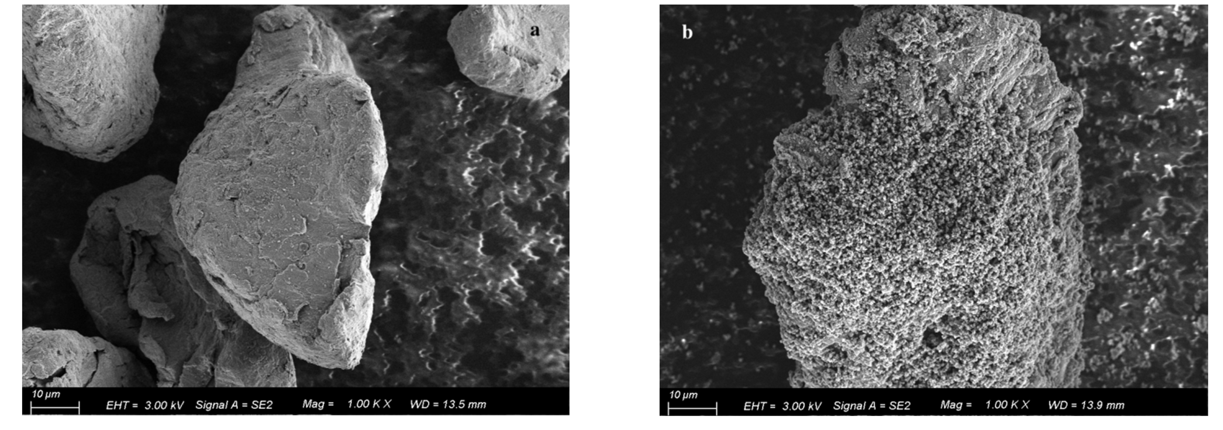
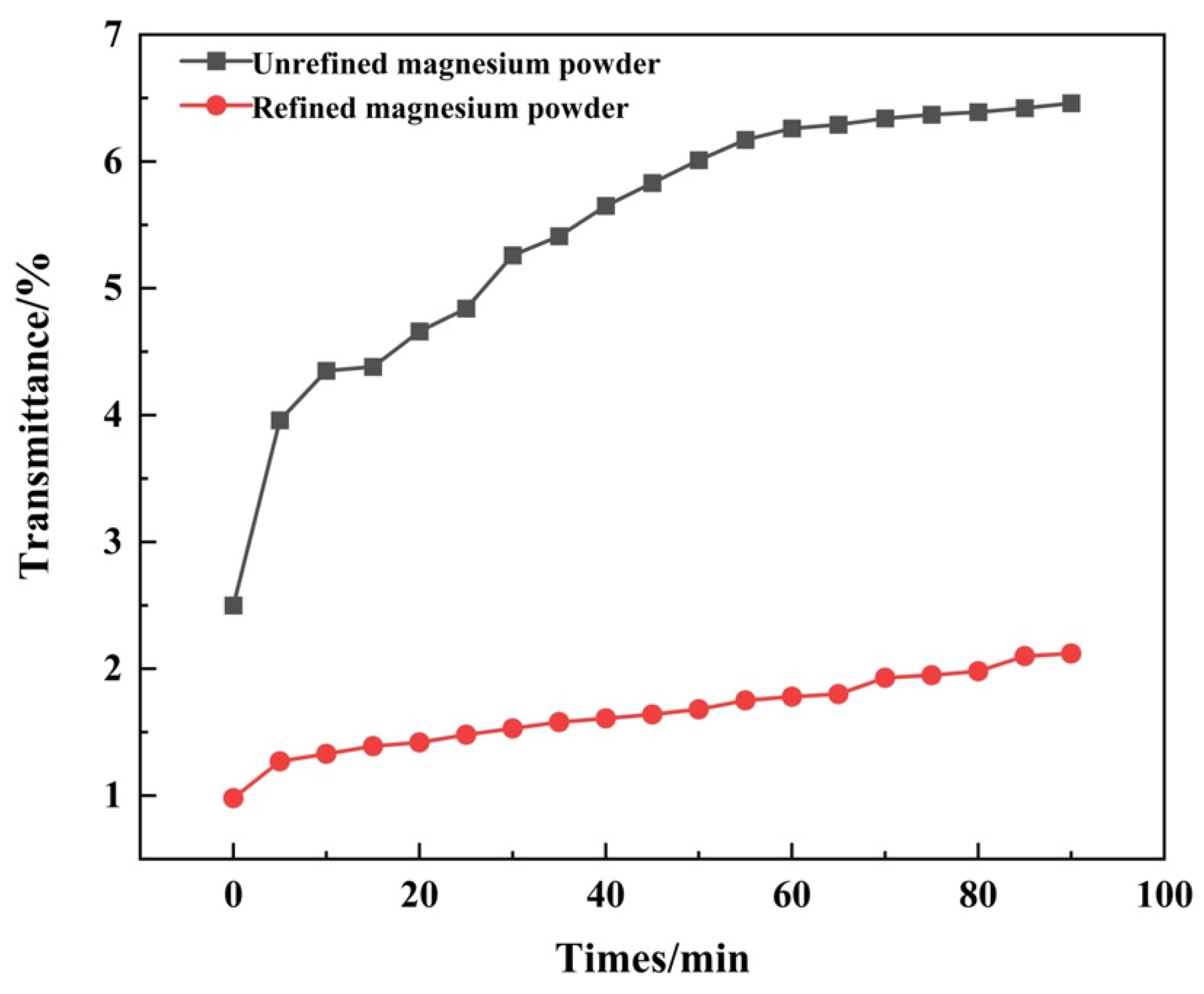
In order to improve the settling of the solid filler in the light-curing resin, magnesium powder was etched with 0.37% dilute hydrochloric acid to produce pores on the surface of the magnesium powder and reduce the settling of the magnesium powder in the resin slurry. Figure 3 shows the SEM diagram of the raw magnesium powder and the acid-etched magnesium powder, and Figure 4 shows the transmittance-time curve of modified magnesium powder.
As shown in Figure 3, in the scanning electron microscope parameters were accelerating voltage 3 kV, working distance 13.5 mm, magnification 1000 times, and an SE2 detector. From the SEM results, it can be seen in Figure 3a that the raw-material magnesium powder is ellipsoidal, with a rough surface and no pores. After acid corrosion, as seen in Figure 3b, the magnesium powder did not change in terms of its ellipsoidal state, but the surface produced significant changes. In Figure 4, it can be seen that the permeability of raw-material magnesium powder rose sharply at 0–10 min; at 20–40 min, the rise rate was slightly slower; after 70 min, the trend tended to stabilize, and at 90 min, the transmittance was 6.46%. After the modification of magnesium powder with the increase in time, the rate of transmittance rose more slowly, with a settling time of 85 min; after becoming stable, the 90 min transmittance was only 2.12%. The surface of unmodified magnesium powder is smooth. After mixing with the resin, magnesium powder particles will settle downward in the resin. During the downward settlement, magnesium powder particles will maintain a certain rate of decline. Magnesium powder particles corroded by hydrochloric acid will have pores on the surface. The generation of pores will increase the specific surface area of the particles, thus enhancing the adsorption capacity, so the suspension performance is improved. Compared with unmodified magnesium powder, after the modification of magnesium powder, the transmittance change is smaller, indicating that modified magnesium powder settles better and will be more closely combined with resin slurry.

3.2. Luminous Performance

We ignited the illuminant, combustible lighting shell, and resin pillar separately, compared the combustible lighting shell, illuminant, and resin pillar under combustion in terms of flame color, combustion spectrum, and luminous intensity, and determined whether the three components’ flame color and combustion spectra were close to the data of the illuminant and combustible lighting shell. The combustion effect is shown in Figure 5.
Figure 5a is for t = 5 s when the illuminant is in the burning state; Figure 5b is for t = 8 s when the combustible lighting shell is in the burning state; Figure 5c is for t = 2 s when the resin pillar is in the burning state. From Figure 5, it can be seen that the flame color of the three combustion processes is yellow. The color is the same, which indicates that the burning of the combustible lighting shell will not have an effect on the burning effect of the illuminant. The combustible lighting shell burning process produces a yellow flame and the brightness, burning flame diffusion, and burning process flame shape are essentially unchanged; the burning interface is obvious, and there is no black smoke, but a small amount of residue is generated. The burning residue mass is 0.351 g, with a residue rate of 7.28%, and the combustible lighting shell’s overall burning time is 15 s.
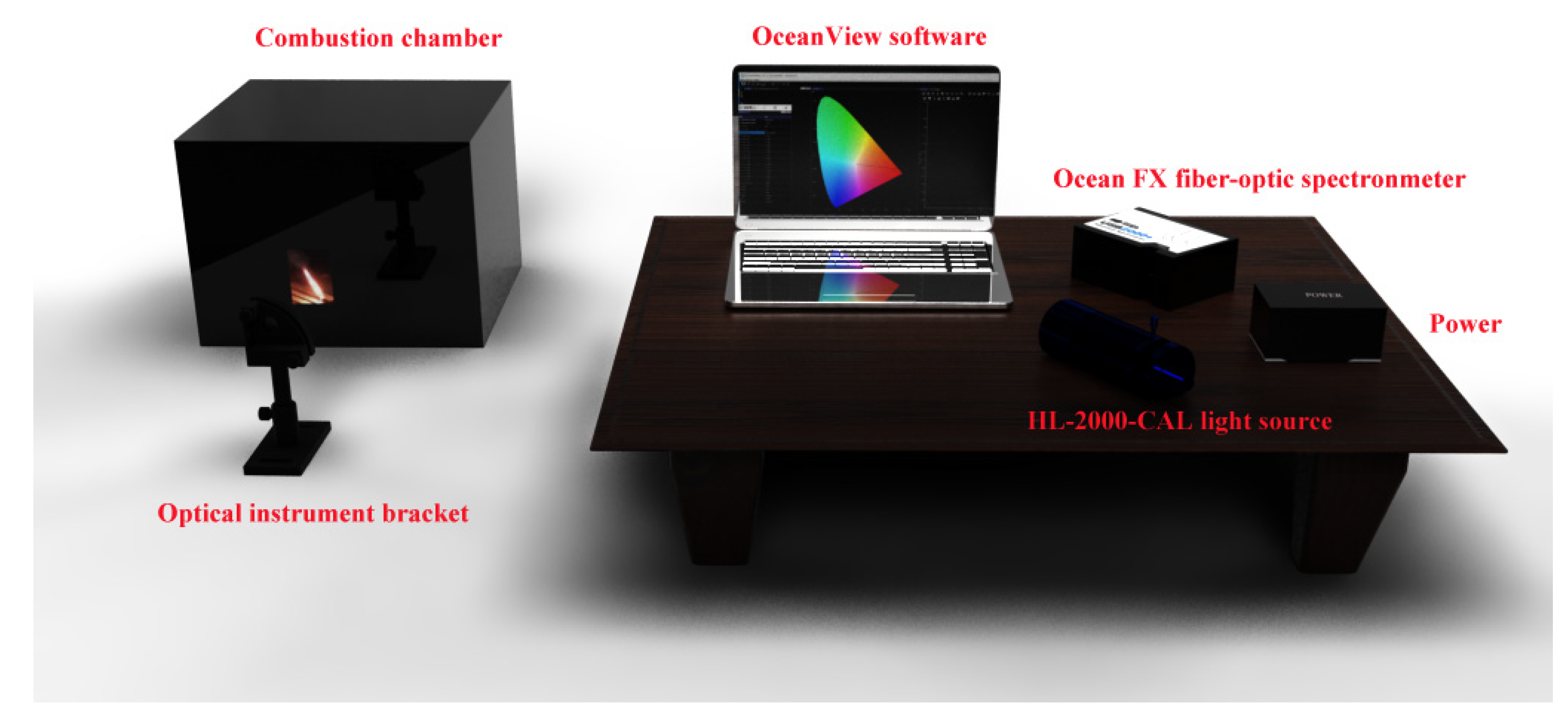
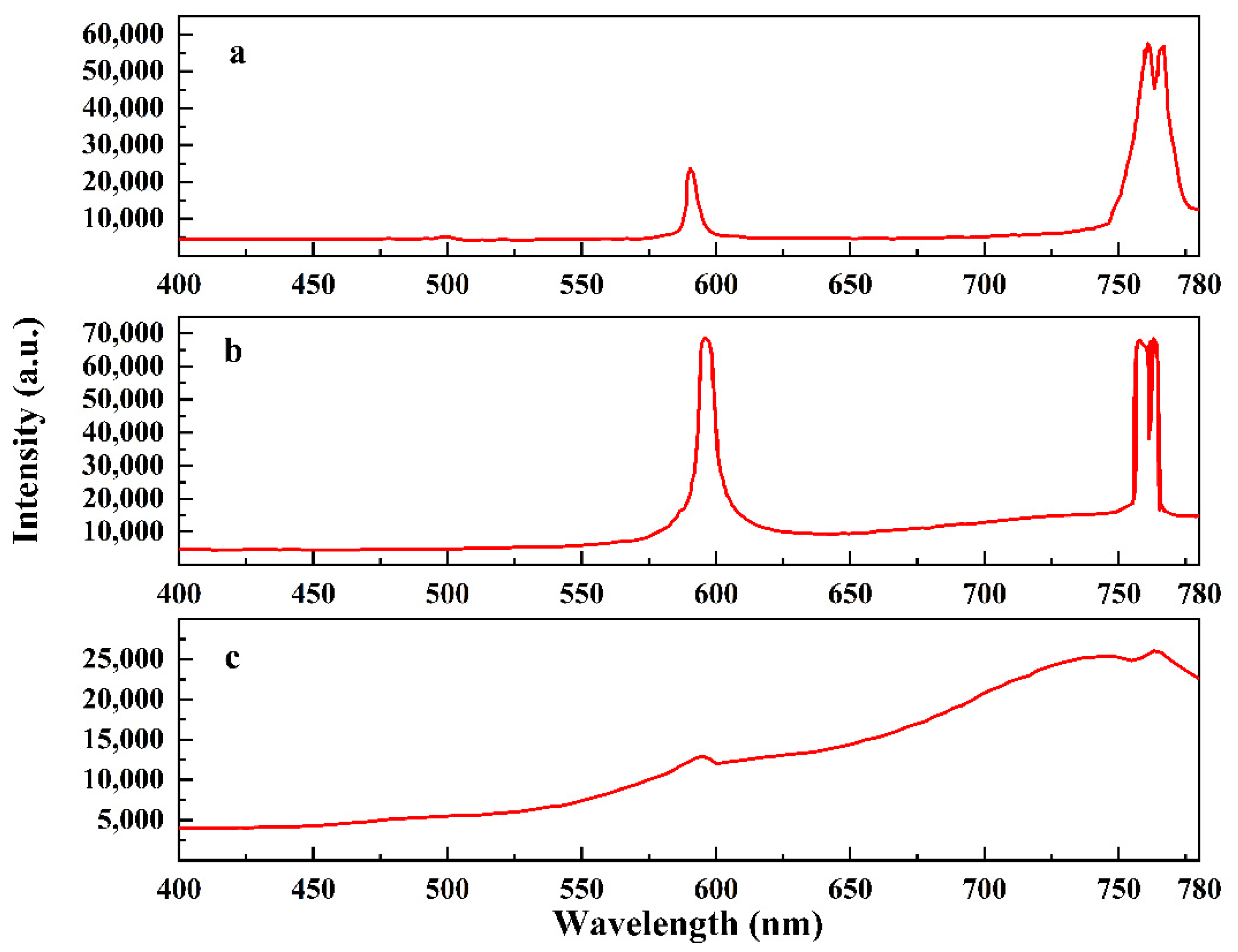
Spectral testing was performed using OceanView software version 2.0.7, powered by Ocean insight. (New York, NY, USA). Firstly, parameters were set for the software; the Ocean FX fiber spectrometer was connected to an HL-2000-CAL calibration light source to obtain the reference background and dark background, and then the fiber was connected to the fiber hole of the detector holder, so that the fiber was aligned with the combustion chamber, and the distance of the fiber from the sample to be tested was 1 m. The sample was placed in the combustion chamber for combustion, and the relevant parameters were obtained by the software; the experimental setup is shown in Figure 6. The illuminant, combustible lighting shell, and resin pillar were ignited for the optical performance test, and the flame radiation spectral radiation was obtained as shown in Figure 7, while the light intensity-time curve is shown in Figure 8.
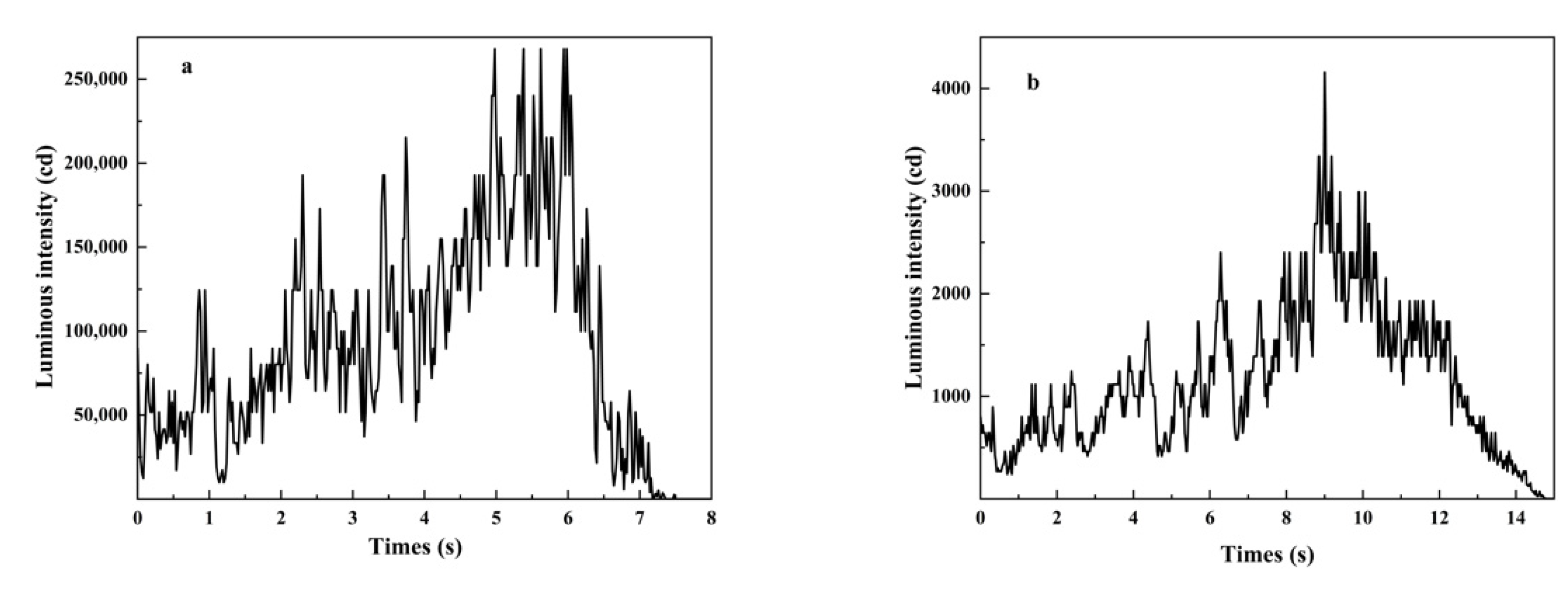
Figure 7a is the combustion radiation spectrum of the illuminant; the radiation peak is located at 591 nm for the radiation peak of Na. The peak values of the combustion spectra are consistent with the literature [20]. Figure 7c is the combustion radiation spectrum of the resin pillar; the radiation peak is located at 595 nm for the radiation peak generated by the combustion of hydrocarbons. Figure 7b is the combustion spectrum radiation peak of the combustible shell; the radiation peak is also located at 595 nm. As the shell composition contains NaNO3 and resin slurry, so the radiation peaks at this location for Na and hydrocarbons are both combustion radiation peaks, but, because the hydrocarbon radiation intensity is small, it will not have a significant impact on the combustible lighting shell’s combustion effect. As can be seen from Figure 7, the flame combustion spectrum of the combustible shell is consistent with the illuminant combustion spectrum, indicating that the combustible shell and the illuminant correspond well. As can be seen from Figure 8, there is 1 g of illuminant burning light intensity of 363,299.12 cd. This result is consistent with the reference book [2], and a combustible shell burning light intensity of 17,188.97 cd, indicating that the combustible shell can give the illuminant an additional 4.73% of light intensity. Under the same size of ∅ 17 mm × 15 mm, where the mass of traditional low-carbon steel illuminating candle shell is 17.85 g, the total mass of the illuminating candle is 18.85 g, the luminous intensity of the illuminating candle is 363,299.12 cd, the luminous intensity of the illuminating candle per unit mass is 19,273.16 cd. Where the mass of the combustible lighting shell is 4.805 g, the total mass of the illuminating candle is 5.805 g, the luminous intensity of the illuminating candle is 380,488.09 cd, and the luminous intensity of the illuminating candle per unit mass is 65,544.89 cd. Compared with the traditional low-carbon steel shell, the luminous intensity per unit mass of combustible shell is higher. In summary, it can be explained that the combustible shell shows not only a good flame combustion spectrum and illuminant combustion spectrum, but also can provide a certain amount of light intensity to the illuminant combustion.

3.3. Mechanical Properties of Combustible Lighting Shell Specimens

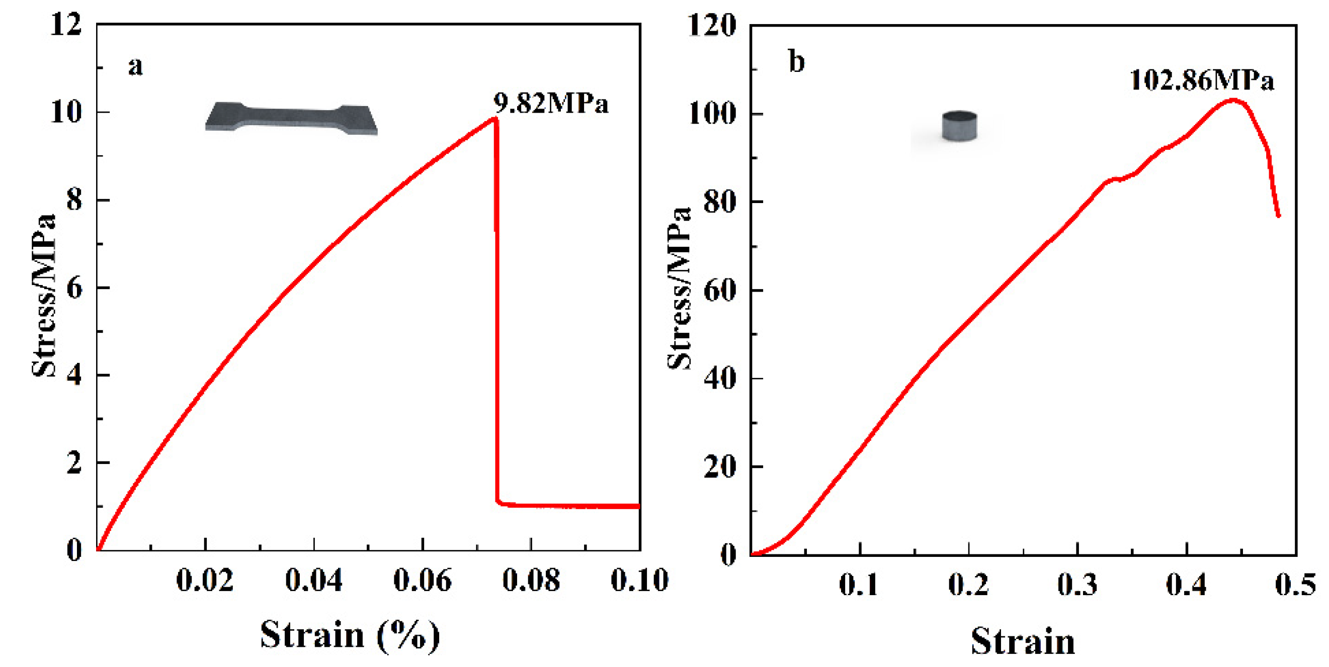
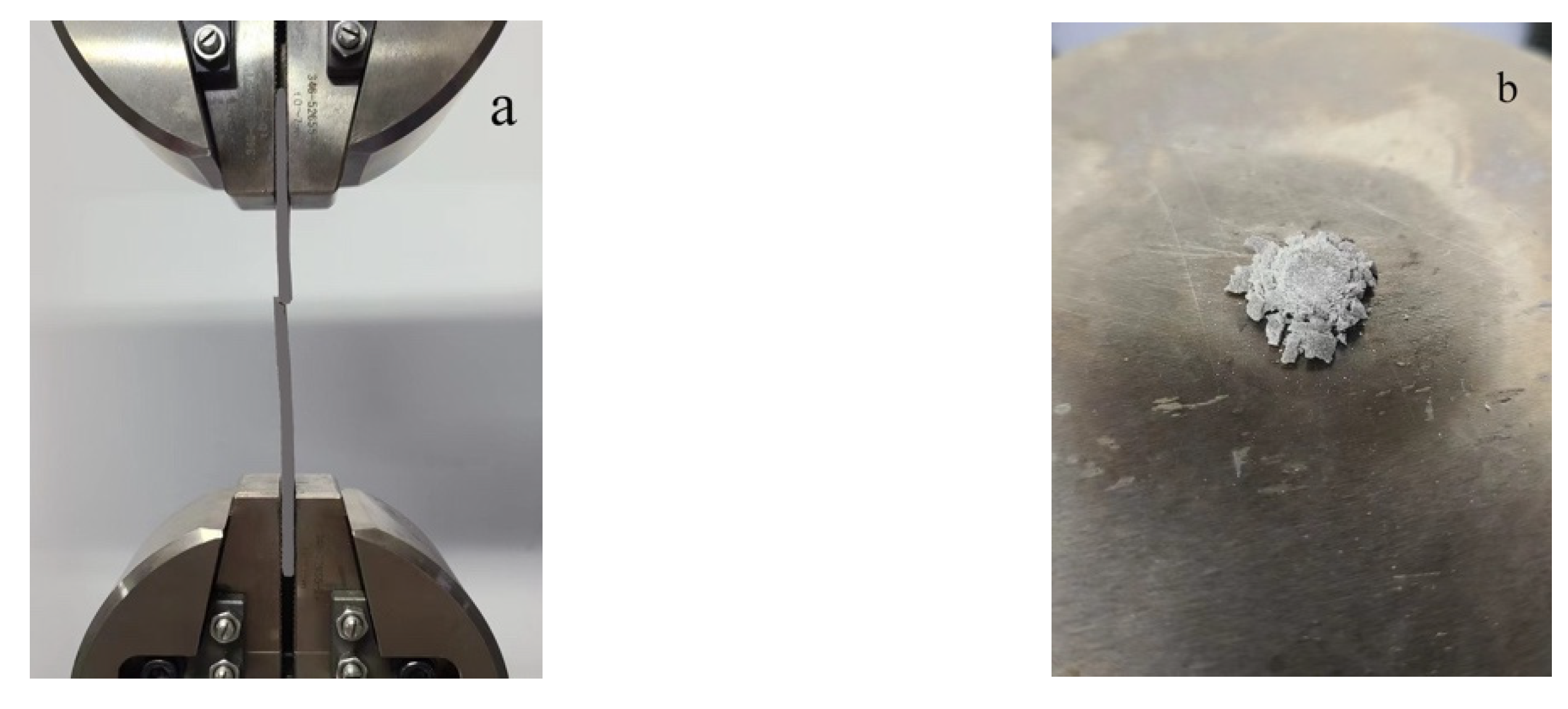
Using a universal testing machine, under the condition of temperature 25 °C and relative humidity 50%, the test specimen was printed into a dumbbell shape for the tensile strength test, with a size of 200 mm × 20 mm × 8 mm; the test specimen was printed into a cylindrical shape for the compressive strength test, with a size of 6 mm × 3 mm, so that the compression speed and tensile speed were assessed under 1 mm/min conditions. The compressive and tensile properties of the printed samples were tested under the same conditions three times, and the results were averaged. The stress-strain curve is shown in Figure 9a,b, the effect of the specimen after fracture is shown in Figure 10.
From Figure 9 and Figure 10, it can be seen that the fracture position obtained in both tensile and compression tests is the middle point, and it can be seen that the specimen produces only very minor elongation with the increase in tensile force in the tensile test of the specimen. When the tensile load increased to a certain degree, the specimen fractured in the middle, as shown in Figure 10a, and the fracture surface was relatively flat. The tensile strength was 9.82 MPa. Since the material is a brittle material, the tensile strength is close to the resin-based energetic material [19], but less than the resin-based fiber material, because the fiber material has a macromolecular chain structure [13].
The stress of the specimen increased sharply to a peak with the increase in strain, and it then decreased slowly, indicating that the pillar was deformed and broken at this time, as shown in Figure 10b. The compressive strength of the specimen was 102.86 MPa. In summary, it could be seen that the tensile and compressive properties of the specimen obtained through 3D printing are very good.

3.4. Compatibility of Combustible Lighting Shell

Differential scanning calorimetry (DSC) is one of the most important characterization tools to study the compatibility of solid fillers [21]. The shells were mixed with sodium nitrate and magnesium powder, respectively, and DSC tests were performed after curing. The DSC curves before and after the addition of NaNO3, Mg, and NaNO3 + Mg to the light-cured resin are shown in Figure 11.
When evaluating the compatibility of a combustible lighting shell, according to GJB 5383.11-2005, it is considered to possess good compatibility when the peak temperature change amounts to ΔTp ≤ 2 °C, and poor compatibility when ΔTp ≥ 5 °C. From Figure 11, the first exothermic peak of NaNO3 is 310.5 °C, and the exothermic peak of NaNO3 mixed with resin is 311.333 °C—that is, the decomposition peak of NaNO3 is shifted back by 0.833 °C after adding resin. The first exothermic peak of Mg is 610.181 °C, the exothermic peak of Mg mixed with resin is 611.459 °C, and the decomposition peak of Mg is shifted back by 1.278 °C after adding resin. The first exothermic peak of NaNO3 + Mg is 365.5 °C, the exothermic peak of NaNO3 + Mg mixed with resin is 367.333 °C, and the decomposition peak of NaNO3 + Mg after adding resin is shifted back by 1.833 °C. ΔTp values were less than 2 °C, so NaNO3 and Mg were more compatible with the light-curing resin.

3.5. Moisture Absorption Test of Combustible Lighting Shell

The combustible lighting shell was placed under the condition of constant high humidity, and the hygroscopic performance of the shell was tested in terms of the amount of weight change before and after the experiment, with reference to GJB 5472.7-2005, to evaluate the results regarding the hygroscopicity of the shell. Firstly, it was dried in a drying oven at a temperature of 55 °C for 24 h, and then it was placed at a temperature of 23 °C and a humidity of 50% for 24 h, and finally kept at a temperature of 30 °C and a humidity of 95% for 144 h. Five rounds of combustible lighting shells were used as a group of specimens, and the results of shell weight change are shown in Table 1; the results were averaged to obtain a weight change rate of 0.44%.
In a humid air environment, magnesium powder is active and easy to oxidize. NaNO3 is reduced to NH3 and NaOH. NH3 dissolves in water to form NH3OH and then reacts with some NaNO3 to form NaOH. The effective components in the shell are reduced, which affects the combustion performance. However, the DLP light-curing method was adopted here. Magnesium powder and sodium nitrate were dispersed in the light-curing resin. The light-curing resin has good stability and is not easily decomposed in a humid environment. At the same time, the contact area of magnesium powder and sodium nitrate with oxygen and water in the air is reduced, which hinders the occurrence of oxidation and decomposition, and the aging speed of the shell is reduced. Therefore, it can be seen that the anti-aging performance of the combustible lighting shell is good.

4. Conclusions

We obtained a combustible lighting candle shell formulation of bisphenol A type epoxy acrylate (EA)/six functional groups of polyurethane acrylate (PUA)/1,6-hexanediol diacrylate (HDDA) hydroxypropyl acrylate (HPA)/2,4,6-trimethylbenzoyl-diphenylphosphine oxide (TPO)/additives (leveling agent, defoamer, bond promoter)/magnesium (Mg)/sodium nitrate (NaNO3), whose formulation mass fraction is: 5.71%/22.85%/15.24%/3.81%/1.91%/0.48%/9%/41%.
A combustible lighting candle shell was successfully printed; the shell size was ∅ 17 mm × 15 mm, wall thickness was 3 mm, bottom thickness was 3.4 mm, and the shell mass was 4.805 g; the interior of the shell was flat, the solid filler and resin slurry were compatible, the combustion was uniform and stable, the combustion interface was obvious, and no black smoke was generated. Moreover, the combustion residue mass was 0.351 g, and the residue rate was 7.28%; the transmittance of modified magnesium powder could reach 2.12%, which is three times lower than that of unmodified magnesium powder. The shell has good mechanical properties; the compressive strength is 102.86 MPa, tensile strength is 9.82 MPa, and the combustible shell’s combustion radiation spectrum is consistent with the illuminant combustion spectrum; moreover, it can provide 4.73% of light intensity for the illumination candle. This paper can provide a new idea for lighting shells.

Author Contributions

Methodology, H.W. and S.B.; Software, H.W.; Conceptualization, S.B.; Validation, H.W., B.Z. and L.L.; Formal Analysis, S.B.; Investigation, H.W., B.Z. and L.L.; Resources, S.B.; Data Curation, H.W.; Writing—Original Draft Preparation, H.W.; Writing—Review and Editing, H.W. and S.B.; Visualization, H.W.; Supervision, S.B.; Project Administration, S.B. All authors have read and agreed to the published version of the manuscript.

Funding

This research received no external funding.

Institutional Review Board Statement

The study did not require ethical approval.

Informed Consent Statement

The study did not involve humans.

Data Availability Statement

The study did not report any data.

Conflicts of Interest

The authors declare that they have no known competing financial interests or personal relationships that could have appeared to influence the work reported in this paper.

References

  1. Back, S.; Son, Y.; Lim, S.; Myung, I. Storage life estimation of magnesium flare material for 81 mm illuminating projectile. J. Korea Inst. Mil. Sci. Technol. 2015, 18, 267–274. [Google Scholar] [CrossRef] [Green Version]
  2. Berger, B. Military Pyrotechnics. CHIMIA 2004, 58, 363. [Google Scholar] [CrossRef]
  3. Lu, E. Artillery Flare Design; National Defense Industry Press: Beijing, China, 1978. [Google Scholar]
  4. Li, D.; Ding, Y.; Wang, Y. Improvement of lighting candle payload. J. Ordnance Equip. Eng. 2008, 29, 3. [Google Scholar] [CrossRef]
  5. Liu, J.; Yu, Y.; Yan, X. Measurement and Calculation of Combustion Performance of Combustible Cartridge Under High Pressure. J. Ballistics. 2017, 29, 54–57. [Google Scholar]
  6. Li, Y.; Guo, D.; Zhao, C.; Zhou, W.; Xu, F. Characterization of Combustible Cartridge Cases Enhanced by Novel Energetic Fibers. Chin. J. Energetic Mater. 2009, 17, 5. [Google Scholar] [CrossRef]
  7. Putra, N.E.; Leeflang, M.A.; Minneboo, M.; Taheri, P.; Fratila-Apachitei, L.E.; Mol, J.M.C.; Zhou, J.; Zadpoor, A.A. Extrusion-based 3D printed biodegradable porous iron. Acta Biomaterialia. 2021, 121, 741–756. [Google Scholar] [CrossRef] [PubMed]
  8. Kollamaram, G.; Croker, D.M.; Walker, G.M.; Goyanes, A.; Basit, A.W.; Gaisford, S. Low temperature fused deposition modeling (FDM) 3D printing of thermolabile drugs. Int. J. Pharm. 2018, 545, 144–152. [Google Scholar] [CrossRef] [PubMed] [Green Version]
  9. Cao, L.; Tian, L.; Peng, H.; Zhou, Y.; Lu, L. Constrained stacking in DLP 3D printing. Comput. Graph. 2021, 95, 60–68. [Google Scholar] [CrossRef]
  10. Vadodaria, S.; Mills, T. Jetting-based 3D printing of edible materials. Food Hydrocoll. 2020, 106, 105857. [Google Scholar] [CrossRef]
  11. Karakurt, I.; Lin, L. 3D printing technologies: Techniques, materials, and post-processing. Curr. Opin. Chem. Eng. 2020, 28, 134–143. [Google Scholar] [CrossRef]
  12. Li, M.; Yang, W.; Xu, M.; Hu, R.; Zheng, L. Study of photocurable energetic resin based propellants fabricated by 3D printing. Mater. Design. 2021, 207, 109891. [Google Scholar] [CrossRef]
  13. Yang, W.; Hu, R.; Zheng, L.; Yan, G.; Yan, W. Fabrication and investigation of 3D-printed gun propellants. Mater. Design. 2020, 192, 108761. [Google Scholar] [CrossRef]
  14. Li, M.; Gao, Y.; Hu, R.; Wang, Q.; Yang, W. Thermal study of APNIMMO/CL-20 based propellants fabricated by 3D printing. Thermochim. Acta. 2021, 706, 179072. [Google Scholar] [CrossRef]
  15. Zhou, M.; Nan, F.; He, W.; Wang, M. Design and Preparation of Propellant 3D Printer Based on Extrusion Deposition Technology. Chin. J. Energetic Mater. 2021, 29, 6. [Google Scholar] [CrossRef]
  16. Dunju, W.; Changping, G.; Ruihao, W.; Baohui, Z.; Bing, G.; Fude, N. Additive manufacturing and combustion performance of CL-20 composites. J. Mater. Sci. 2020, 55, 2836–2845. [Google Scholar] [CrossRef]
  17. Quan, H.; Zhang, T.; Xu, H.; Luo, S.; Nie, J.; Zhu, X. Photo-curing 3D printing technique and its challenges. Bioact. Mater. 2020, 5, 110–115. [Google Scholar] [CrossRef] [PubMed]
  18. Wang, B.; Zhang, Z.; Pei, Z.; Qiu, J.; Wang, S. Current progress on the 3D printing of thermosets. Adv. Compos. Hybrid Mater. 2020, 3, 462–472. [Google Scholar] [CrossRef]
  19. Chen, Y.; Ba, S.; Ren, H. Additive Manufacturing of a Special-Shaped Energetic Grain and Its Performance. Micromachines 2021, 12, 1509. [Google Scholar] [CrossRef]
  20. Meyerriecks, W.; Kosanke, K.L. Color values and spectra of the principal emitters in colored flames. J. Pyrotech. 2003, 18, 710–731. [Google Scholar]
  21. Ba, S.; Yang, Y.; Shen, H.; Wang, S.; Sun, W. Delay Property of Energetic Grain via Digital Light Processing Photocurable 3D Printing. Chin. J. Energetic Mate. 2022, 30, 363–369. [Google Scholar] [CrossRef]
Figure 1. Resin slurry configuration process.
Applsci 12 10401 g001
Figure 2. The shell of the illuminant candle: (a) shell main view; (b) top view of shell; (c) structural of low-carbon steel illuminating candle.
Applsci 12 10401 g002
Figure 3. SEM images of raw magnesium powder and etched magnesium powder: (a) the SEM image of raw magnesium powder; (b) the SEM image of magnesium powder after acid etching.
Applsci 12 10401 g003
Figure 4. Transmittance-time curve of modified magnesium powder.
Applsci 12 10401 g004
Figure 5. Flame color during combustion: (a) illuminant; (b) combustible illuminant shell; (c) resin pillar.
Applsci 12 10401 g005
Figure 6. Combustion radiation spectrum test device.
Applsci 12 10401 g006
Figure 7. Illuminant, combustible illumination shell, and resin pillar combustion radiation spectrum: (a) illuminant; (b) combustible illuminant shell; (c) resin pillar.
Applsci 12 10401 g007
Figure 8. Illuminant and shell combustion light intensity: (a) illuminant luminous intensity; (b) combustible shell luminous intensity.
Applsci 12 10401 g008
Figure 9. Specimen tensile and compressive strength curves: (a) stress-strain curve of tensile strength; (b) stress-strain curve of compressive strength.
Applsci 12 10401 g009
Figure 10. Specimen tensile and compression tests ((a) tensile; (b) compression).
Applsci 12 10401 g010
Figure 11. DSC curves of the compatibility of each component of the shell ((a) NaNO3, NaNO3 + resin; (b) Mg, Mg + resin; (c) NaNO3 +Mg, NaNO3 +Mg + resin).
Applsci 12 10401 g011
Table 1. Results of hygroscopicity of shell.
NumberShell Quality/gQuality of Shell after Hygroscoping/gShell Added Mass/gRate of Weight Change/%
14.8054.82820.02320.48
24.8114.82930.01830.38
34.7974.81950.02250.47
44.8074.82680.01980.41
54.8154.83780.02280.47
Publisher’s Note: MDPI stays neutral with regard to jurisdictional claims in published maps and institutional affiliations.