Article

CFD Analysis on the Heat Dissipation of a Dry-Lubricated Gear Stage

Gear Research Center (FZG), Department of Mechanical Engineering, School of Engineering and Design, Technical University of Munich, Boltzmannstraße 15, D-85748 Garching, Germany
*
Authors to whom correspondence should be addressed.
Appl. Sci. 2022, 12(20), 10386; https://doi.org/10.3390/app122010386
Submission received: 9 September 2022 / Revised: 4 October 2022 / Accepted: 10 October 2022 / Published: 15 October 2022
(This article belongs to the Special Issue Tribology and Mechanical Transmissions)

Abstract

:
Power losses in gearboxes result in frictional heating. Sufficient heat transfer from the gearbox to the environment is required for reliable operation. The heat dissipation from gears is linked to their interaction with fluids in the gearbox. Recent research has demonstrated the use of Computational Fluid Dynamics (CFD) to predict the gearbox fluid flow and no-load losses in an isothermal manner. This study focuses on a numerical analysis of the heat dissipation within a dry-lubricated gearbox under atmospheric conditions. Spur gears and helical gears are investigated. The air flow in the gearbox as well as the heat dissipation over the gear surfaces are evaluated in detail. The results show that the gear geometry and the circumferential speed have a strong impact on the air flow. Especially, the axial inflow of air to the gears has a great influence on the heat dissipation. Conveying effects of helical gears lead to a multidirectional airflow, resulting in higher values of the heat transfer coefficient on the gear surface compared to spur gears.

1. Introduction

A deep understanding of the interplay of machine elements in geared transmissions is fundamental for an optimal design. Except for selected space applications [1], a fluid is present in a gearbox. The interaction of rotating machine elements with fluid causes a fluid flow connected with no-load power loss. According to ISO/TR 14179-2, the gear-based no-load gearbox power loss includes power losses due to churning, squeezing, impulse, and ventilation effects. Churning refers to the rotation of gears in a liquid fluid sump and the consequent distribution of liquid fluid. Squeezing describes the displacement of liquid fluid from the tooth gaps of meshing teeth. Impulse effects occur when injected liquid fluid impinges rotating gears. Ventilation refers to the interaction of rotating gears with a gaseous fluid (Quiban et al. [2] and Liu et al. [3]).
In dry-lubricated gearboxes under atmospheric conditions, only ventilation occurs. Höhn et al. [4] describe the great potential of dry-lubricated gearboxes for resource- and energy-efficient operation in suitable applications. Recent studies on dry-lubricated rolling-sliding contacts were carried out by Yilmaz et al. [5], Sklenak et al. [6], and Simo Kamga et al. [7]. Hofmann et al. [8] analyzed the friction and temperature behavior. Bobzin et al. [9] investigated the influence of different coating materials on the transfer film formation. The authors point out the potential of dry-lubricated gears that have not yet been sufficiently investigated. Particularly, the sufficient dissipation of frictional heat is crucial to avoid thermal load limits, as shown by Handschuh [10]. Höhn et al. [11] and Yilmaz et al. [12] point out that the heat dissipation from gears is especially crucial [13]. In atmospheric dry-lubricated gearboxes, only gaseous fluid flow in the gearbox provides cooling. It determines the heat transfer and the inner temperature distribution [14].
In thermodynamics, dimensionless properties such as the Reynolds number R e , the Prantl number P r , and the Nusselt number N u are central components. The Nusselt number N u is defined by the quotient of the heat transfer coefficient (HTC) h, the thermal conductivity λ , and the reference length D:
N u =   h · D λ
A common Nusselt correlation for calculating the heat transfer of a cylinder rotating in water was empirically derived by Becker [15] and adapted by Lebeck [16] for calculating the heat transfer of a cylinder rotating in oil:
N u = 0 . 133   · R e 2 3 · P r 1 3
The author state a validity range of the Nusselt correlation of 103 < Re < 105. In order to calculate the heat dissipation of gears, Nusselt correlations for cylinders rotating in fluid are often considered. Changenet et al. [17] adapted the approach by Lebeck [16] for calculating the heat transfer of gears rotating in oil.
Several studies have addressed the calculation of the heat balance of gearboxes and especially the heat dissipation of gears. Experimental and numerical investigations of the heat transfer coefficient on impingement-cooled gear flanks were carried out by Ayan et al. [18]. The results show that the inflowing oil to the gear surface has a large impact on the heat transfer. Changenet et al. [17] developed a model for predicting power loss that is related to a thermal network. Paschold et al. [19,20] applied the thermal network method to calculate stationary and transient component temperatures in gearboxes. Geiger [21] investigated the heat transfer in gearboxes and developed a parametrizable thermal network to calculate temperature distribution and heat balance. Simplified Nusselt correlations were applied to determine the heat transfer between rotating gears and oil. Despite the good agreement for a broad range of operating conditions, Geiger [21] also reports deviations between calculated and measured gearbox temperatures. The dynamic oil flow within the gearbox was identified as having a strong impact on the heat dissipation of the gears and the housing. This is difficult to consider by simple correlation formulas and should, therefore, be studied in future works.
The fluid flow in gearboxes can be calculated by means of Computational Fluid Dynamics (CFD). Hildebrand et al. [22] show that detailed information on the interaction of gears and fluid can be derived by CFD. Morhard et al. [23] used simulation results to support and improve the gearbox design. Maccioni and Concli [24] provide an overview of applied CFD methods and performed investigations of the lubrication of machine elements and gearboxes. It is shown that the grid-based Finite Volume Method (FVM) is suitable for the simulation of gearbox fluid flow. Shadloo et al. [25] provide an overview on possible applications of the particle-based Smoothed Particle Hydrodynamics (SPH) method in the context of industrial applications. Only few studies have used thermal CFD simulations to investigate the heat dissipation in gearboxes. Korsukova et al. [26] investigated the oil flow and heat transfer in a spur gearbox by means of the FVM. The results show that the intensity of the interaction of rotating gears with oil has a remarkable influence on the heat transfer. The authors emphasize that the validity of thermal CFD must be strengthened, especially by experimental data. Lu et al. [14] analyzed the oil flow and heat transfer within a dip-lubricated aviation gearbox by means of the FVM and confronted simulation results with temperature measurements, stating good accordance. The authors show that a detailed parametrization of the calculation model enables resilient simulation results. Ürlich et al. [27] used SPH simulation to derive information on the fluid distribution in a gearbox that is transferred to a thermal network by means of fluid distribution factors in order to calculate the thermal gearbox behavior.
The literature study shows the importance of sufficient dissipation of frictional heat, especially under dry-lubricated conditions. Detailed knowledge of heat transfer coefficients can improve the gearbox design and avoid thermal load limits. By means of the CFD, a deep understanding of the fluid flow within gearboxes and the underlying mechanisms has been generated. The heat transfer in gearboxes has been poorly analyzed numerically. This study shows a methodology for the numerical calculation of the heat transfer between rotating gears and air in a dry-lubricated gear stage based on the FVM. Mechanisms are analyzed and compared for a spur and helical gear pair. The methodology of the study is presented in Section 2 and the results are discussed in Section 3. Section 4 summarizes the main conclusions.

2. Methods and Materials

In the following, the object of investigation, operating conditions, numerical model, and calculation procedure are described.

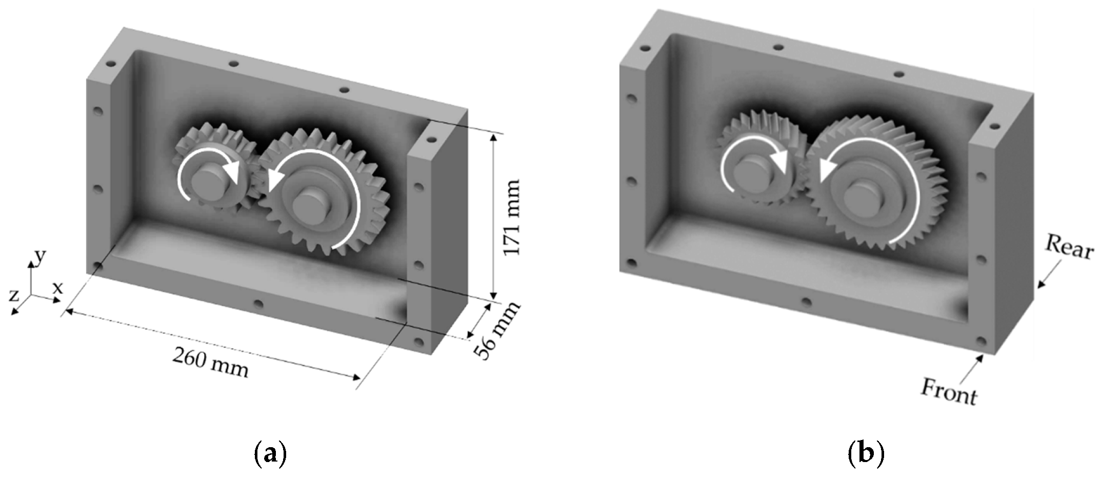
2.1. Object of Investigation

The object of investigation is the single-stage FZG test gearbox, as considered previously by the authors [22]. The test gearbox has a width of 260 mm, a height of 171 mm, and a depth of 56 mm (see Figure 1a). The considered gears are the conventional FZG test gear of type C-PT (gear-C) and a low-loss gear with loss-optimized gear geometry (gear-LL) by concentrating sliding around the pitch point [28]. This makes it interesting for dry-lubricated gearboxes. The geometry of the considered gears is listed in Table 1.
Figure 1a shows the considered gearbox with gear-C and Figure 1b shows that with gear-LL. The investigated rotational direction is visualized and the front and rear side of the gearbox are indicated, which are referred to in Section 3.

2.2. Operating Conditions

The gearbox is considered as dry-lubricated with air under standard conditions as the surrounding fluid. The thermal boundary conditions refer to the experimental data of Geiger [21] for the test gearbox in Figure 1 in stationary conditions. Although he investigated an oil-lubricated gearbox, the measured temperatures are applied in this study due to the lack of experimental data for dry lubrication. Table 2 presents the measured oil temperature Toil, the pinion bulk temperature TM1, and the wheel bulk temperature TM2 for the circumferential speeds vt = {2.0; 5.0; 10.0} m/s at no-load. The material properties are considered as constant per circumferential speed. For both gear geometries gear-C and gear-LL, the same thermal boundary conditions are considered to focus on the influence of the air flow on the heat transfer.
The air temperature Tair is set to Toil. The influence of the circumferential speed is investigated by varying vt = {2.0; 5.0; 10.0} m/s. The rotational direction of the gears is visualized in Figure 1.

2.3. Numerical Modeling and Calculation

In this section, the simulation approach is described with focus on the numerical modeling and calculation. The software Ansys® Fluent 2020/R1 (ANSYS, Inc., Canonsburg, PA, USA) is used. For detailed information on the fundamentals of computational fluid dynamics, the reader refers to the specialized literature, e.g., [29,30].

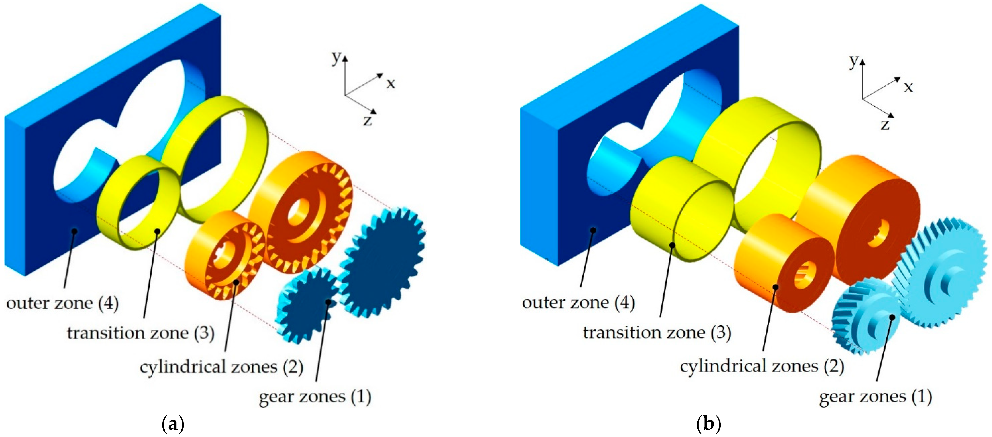
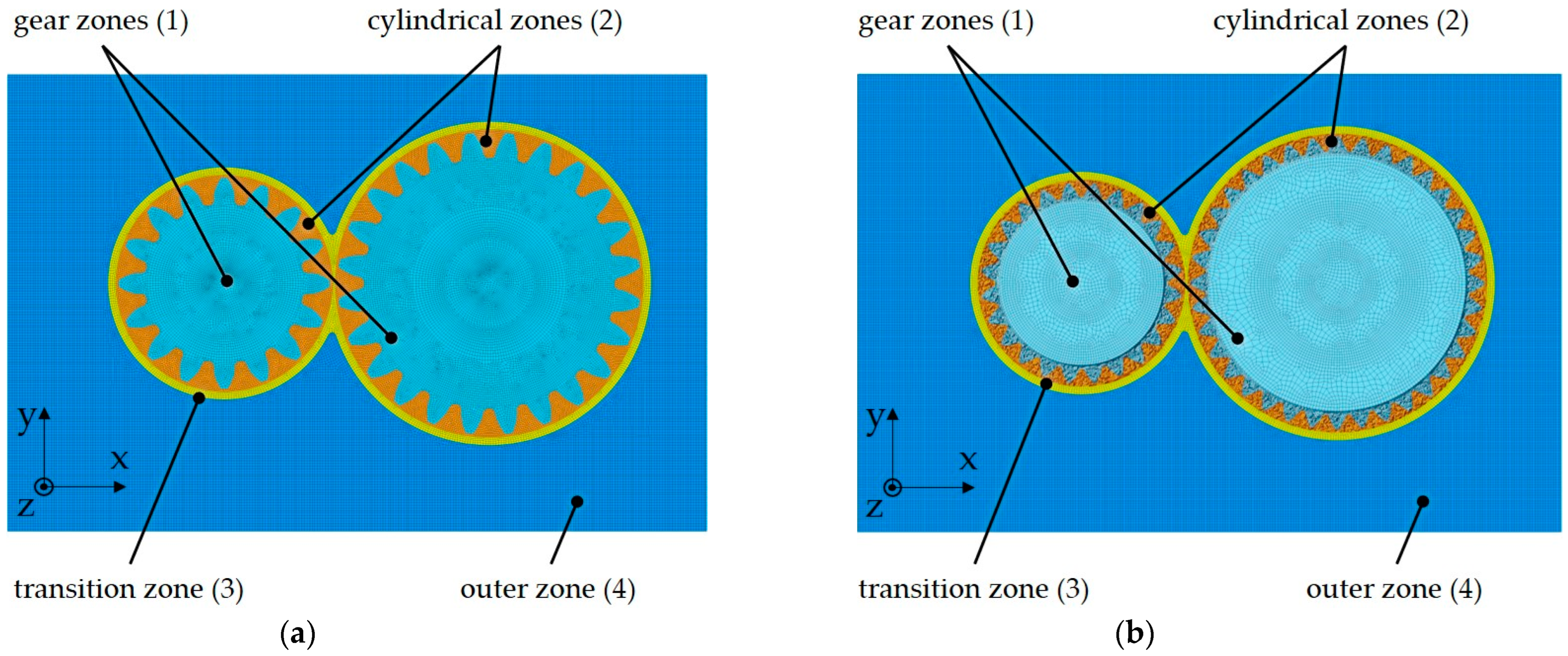
2.3.1. Geometry and Mesh Models

Geometry and mesh models of the considered gearbox and gears are generally based on previous studies by the authors (Liu et al. [3,31,32] and Hildebrand et al. [22]). The modeling of the gear rotation requires a dynamic mesh handling technique, for which the sliding mesh method is used in this study. Therefore, each gear is surrounded by a cylindrical zone rotating with the gear. As the real gear dimensions are investigated, the center distance has to be increased from 91.5 mm to 96.5 mm (+5.5%). Hence, the gear meshing is not explicitly considered. Although this will influence the fluid flow in proximity of the gear meshing, it does not significantly influence the main fluid flow in the gearbox. As the considered gearbox with spur gear-C is symmetrical to the median plane (XY-plane, see Figure 1a), a half model with the symmetry boundary condition is used. For the helical gear-LL, a full model is required. Each model consists of the gear zones (1), the cylindrical zones (2), the transition zone (3), and the outer zone (4). Figure 2 shows the modular structure of the geometry models for gear-C (a) and gear-LL (b).
Mesh models are developed based on the presented geometry models. The gear zones (1) of gear-C are discretized with prismatic and hexahedral elements, whereas the gear zones (1) of gear-LL are discretized with tetrahedral elements. For both investigated gears, the cylindrical zones (2) are discretized with prismatic and hexahedral elements. The transition zone (3) and the outer zone (4) are discretized with hexahedral elements. The transition zone (3) between the gear zones and the outer zone allows a suitable control of the meshing process. Each cylindrical mesh zone (2) is connected with the transition zone (3) via numerical interfaces that enable a consistent calculation of the flow field. The mesh models visualized in Figure 3 are named based on the underlying gear as Meshgear-C (a) and Meshgear-LL (b).
Meshgear-C has an element number of approx. 1.9 M due to the predominant discretization with hexahedral and prismatic cells. Meshgear-LL has an element number of approx. 5.2 M due to tetrahedral elements in the gear zones and full model approach. Detailed information on the mesh models is given in Table 3.
The numerical modeling approach is described in the following Section 2.3.2, Section 2.3.3 and Section 2.3.4. The descriptions are partly based on [22], but reutilized to improve overall comprehension.

2.3.2. Governing Equations

The mathematical modeling of a fluid flow is based on conservation equations for mass, impulse, and energy [30,33]. A prototypical conservation equation [33] reads:
t ρ ϕ   +   · ρ v ϕ F ϕ   =   · Γ   ϕ D ϕ + Q ϕ
The parameters F ϕ and D ϕ describe the convective and diffusive flux of ϕ . The source or sink of the quantity ϕ is described by Q ϕ . Table 4 specifies the parameterization of the conservation equations. Hereby, τ stands for the shear stress tensor, p for the pressure, g for the gravity acceleration vector, h for the enthalpy, and q for the heat flux vector.

2.3.3. Finite Volume Method

The FVM subdivides the calculation domain into finite control volumes (CVs). Equation (4) shows the generic conservation equation for a quantity ϕ in its integral form. It describes the convective (left side) and diffusive flux (first term on the right side) over the surfaces of the CVs. Hereby, V is the volume and S is the surface of a CV. The parameter n stands for the unit vector orthogonal to the specific surface.
S ρ ϕ v · n d S =   S Γ ϕ · n   d S + V Q ϕ   d V
An interpolative approximation of variable values is performed within the solving process. Due to the interrelation of CV averages and CV fluxes over the surfaces, the FVM is conservative.

2.3.4. Turbulence Model

Intense interaction between rotating gears and fluid results in a turbulent fluid flow, especially at high circumferential speeds. For the numerical modeling of fluid flow in gearboxes, the k–ε turbulence model has proven to be suitable [3,34]. It describes turbulence by a velocity and a length scale and is applied in this study. The k–ε turbulence model is further complemented by renormalization operations (renormalization group, RNG) for enhanced performance regarding the modeling of complex turbulent flow [35].

2.3.5. Wall Modeling

In order to describe the interaction of moving solid surfaces with fluid, the numerical calculation of the flow in areas close to the wall is particularly necessary. On the one hand, this can be accomplished by a fine meshing, which can be quantified by a dimensionless distance y+ of less than one. The dimensionless distance y+ is defined by the absolute distance from the wall y , the friction velocity u τ , and the kinematic viscosity ν :
y + = y u τ ν  
On the other hand, the flow in the near-wall region can be described by means of near-wall modeling methods. By wall models, coarser meshes with y+ greater than one can be used [30]. Furthermore, the latest wall models, such as the Menter–Lechner wall model, allow a y+-independent calculation of the flow in areas close to the wall. In this study, the Menter–Lechner wall-function as implemented in Ansys@ Fluent [36] is applied. In addition, a wall adhesion condition is assigned to the walls.

2.3.6. Heat Transfer

There are three physical transport mechanisms of heat transfer, namely conduction, convection, and radiation. Within this work, only convection is considered as it is the dominating mechanism of heat transfer within turbulent flows [37]. The energy equation is solved and the heat dissipation of the gears is calculated. The heat dissipation is evaluated by the heat transfer coefficient (HTC) between the gears and the air. Ansys Fluent provides three different methods for evaluating the HTC, namely the wall-adjacent HTC, the wall function HTC, and the surface HTC. The calculation of the surface HTC h is based on the Newtonian approach by the quotient of the heat flux q and the temperature difference between the wall temperature Twall and reference temperature Tref, see Equation (5).
Because the wall and reference temperatures have fixed values, the calculation of the surface HTC results in a mesh-independent solution in contrast to the wall-adjacent HTC and the wall function HTC. Note that the calculation of the flow field requires a suitable mesh addressing the flow characteristics. Hence, the surface HTC is evaluated in this work.
Ansys Fluent calculates the heat flux q referenced in Equation (5) based on the temperatures Twall and Tref, the fluid properties ρ and c p , the dimensionless temperature T c * , and dimensionless velocity u*.
h = q T w a l l T r e f  
q   =   ρ c p u * T c * D ( T w a l l T r e f ) · T c *  

2.3.7. Simulation Procedure

Figure 4 summarizes the simulation procedure pursued in this work with the modeling and calculation steps, as well as the boundary conditions. First, geometry models of the gearboxes are created that consider the requirements of the dynamic meshing approach, see Section 2.3.1. Second, the mesh models Meshgear-C and Meshgear-LL are developed, as described in Section 2.3.2. Third, the CFD models CFDgear-C and CFDgear-LL are derived based on the numerical modeling approach presented in Section 2.3.2, Section 2.3.3, Section 2.3.4, Section 2.3.5 and Section 2.3.6. A Newtonian fluid behavior is considered.
Hildebrand et al. [22] showed that a consecutive calculation methodology enables the efficient calculation of several simulation cases that are building up on each other. Therefore, a resilient simulation state serves as a starting point of the consecutive simulation of a suitable varied operating condition. A consecutive simulation methodology is also applied in this work to increase the calculation efficiency. In the first simulation step, flow fields for the different gears and circumferential speeds are calculated based on a steady-state and isothermal CFD simulation. For steady-state simulations, the solver does not contain time-dependent terms. Numerical convergence is reached within approx. 5000 iterations. In the second simulation step, transient and thermal CFD simulations are performed based on the steady-state simulation results. The thermal boundary conditions presented in Section 2.2 are considered. In the equations presented in Section 2.3.6, the wall temperature Twall refers to the temperatures TM1 or, rather, TM2 and the reference temperature Tref refers to the air temperature Tair.
A time step that results in a change in rotation angle of the pinion of 0.1° is chosen (Liu et al. [3,31]). The local convergence criterion is set to 10−5 and used for all equations. All calculations are carried out at the Leibnitz Rechenzentrum (LRZ) using 112 cores (Intel Xeon E5-2690 v3 (Intel Corporation, Santa Clara, CA, USA), clock rate 2.6 GHz, and working memory 64 GB). Within a simulated physical time of tsim = 0.5 s, a quasi-stationary state is reached with respect to the convergence of the calculated HTC within the transient CFD simulations.

3. Results

The results of the numerical calculations are analyzed and discussed in the following with a focus on flow fields and HTC between the gears and air.

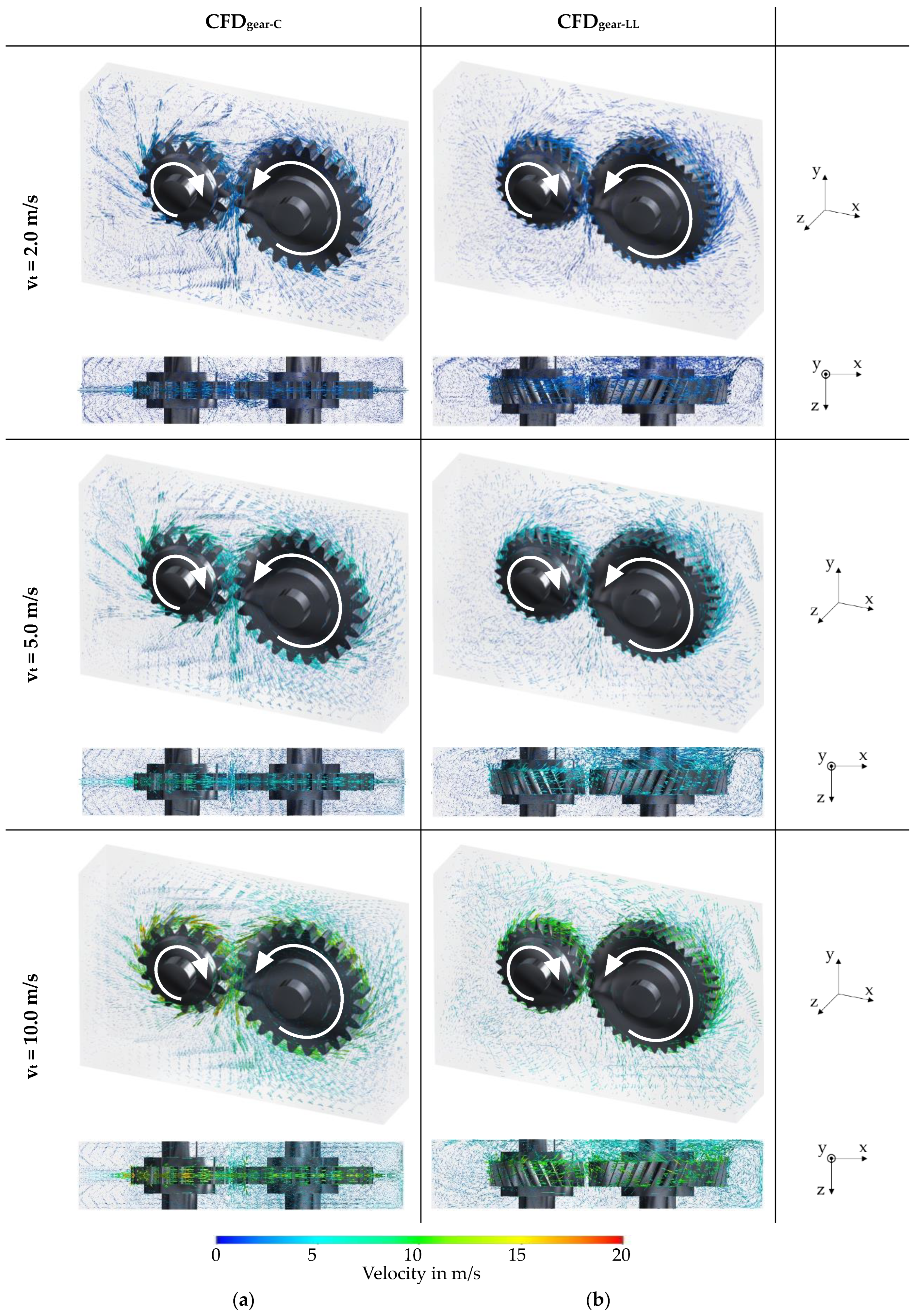
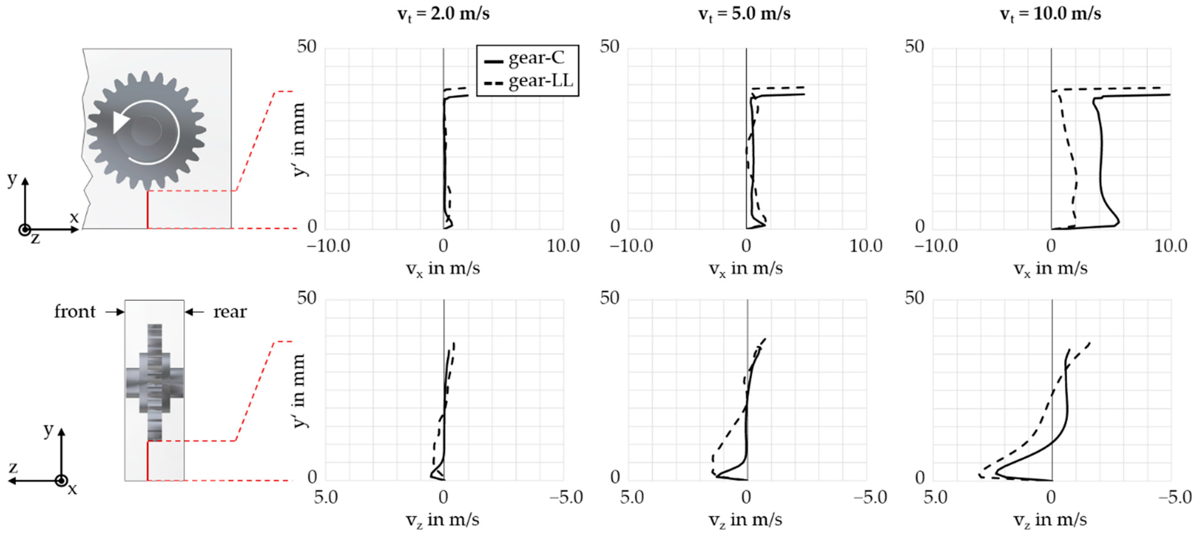
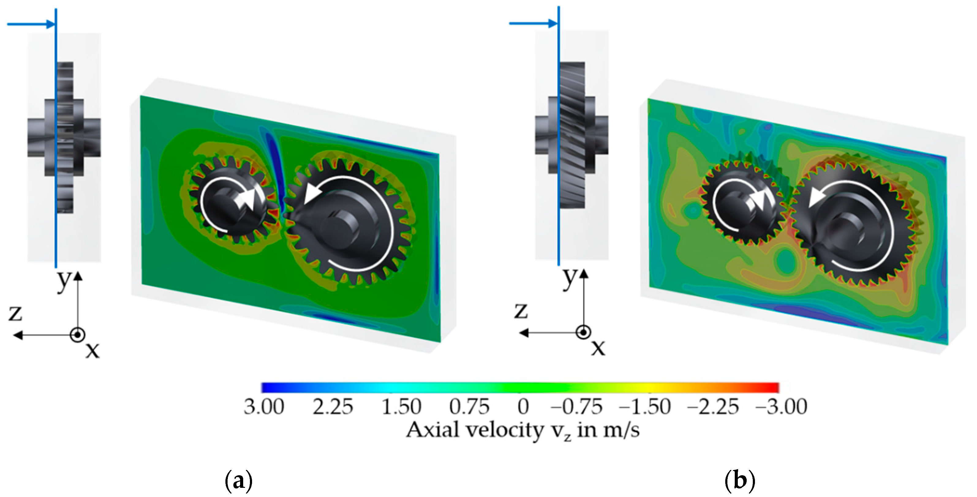
3.1. Analysis of the Isothermal Flow Field

Figure 5 visualizes the steady-state flow fields for the circumferential speeds vt = {2.0; 5.0; 10.0} m/s by vectors that are colored based on the local flow velocity. Figure 5 shows the results for gear-C (a) and for gear-LL (b). It can be seen that the rotating gears drag air in the circumferential direction, especially by the teeth. The air flow around the gears also has a component in the radial direction. The results feature clear similarities to the fluid flow in a dip-lubricated gearbox investigated by Liu et al. [3] and Hildebrand et al. [22], showing oil flowing in the circumferential as well as radial direction due to inertia forces. In the gear meshing zone, the individual air flows of the pinion and wheel encounter each other, which results in an axial deflection and flow.
For gear-C, the flow field in the axial direction (z-direction) is symmetrical to the median plane. Air flows away from the gears in the radial direction. Consequently, air is drawn from the front- and rear side of the gearbox to the rotating gears, thus flowing back to the teeth. This leads to a distinct air flow in the middle of the gear width where the encounter and accumulation of axial air flow and its radial outflow can be observed.
The flow fields for the gear-LL show a distinct radial and axial circulation of the air. Due to the “conveying” effect of the helical gear, air is drawn from the front side of the gearbox and moved to the rear side. From there, the air flows back along the side walls to the front wall of the housing. In the process, turbulence forms in the outer areas of the gearbox housing.
The results show higher flow velocities with increasing circumferential speed. High flow velocity is predominant especially near the gears. In the outer regions of the housing, a comparable low velocity can be stated. The comparison of gear-C and gear-LL shows that, for each configuration, the rotating wheel generates a more distinct flow field compared to the pinion. A much stronger multidirectional air flow in the gearbox is predominant for gear-LL compared to gear-C. The results suggest that, for the geometries studied, the tooth width and helix angle have a greater influence on the interaction of the gears with the air than the tip diameter and tooth module.
Figure 6 visualizes the flow velocities vx in the x-direction and vz in the z-direction below the wheel of gear-C and gear-LL for vt = {2.0; 5.0; 10.0} m/s. The velocities are evaluated on an evaluation line that is shown on the left exemplarily for gear-C. The vertical position on the evaluation line is represented by y’. The flow velocity vx is zero at the gearbox housing bottom and equal to the circumferential speed of the wheels at the tip circle. For both gears, vx decreases strongly in proximity of the tip circle. Then, vx is relatively constant. At vt = 10 m/s, vx shows a higher value for gear-C compared to gear-LL. Hence, gear-C generates a stronger flow field in the radial direction. The flow velocity vz is negative in proximity of the tip circle, which means a flow toward the rear of the gearbox. Near the gearbox bottom, vz is positive, meaning a flow toward the front of the gearbox. The flow velocity vz is, over wide ranges, higher for gear-LL compared to gear-C, which indicates a more pronounced conveying effect of the helical gear.
It can be summarized that the steady-state flow fields show a physically plausible behavior and enable a differentiation between the investigated gears. The steady-state flow fields serve as a valid starting point for the transient and thermal analysis.

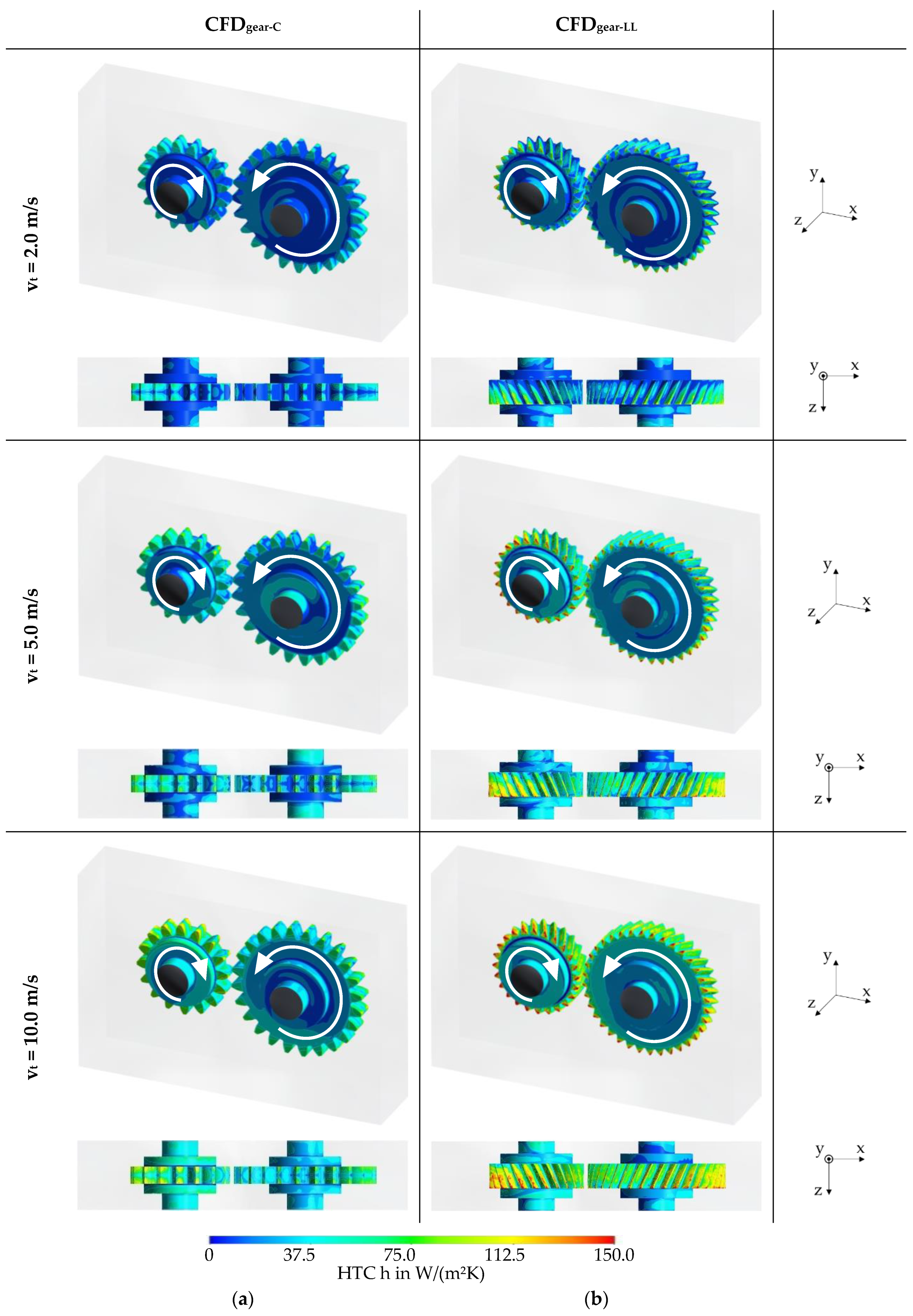
3.2. Analysis of the Heat Transfer Coefficient

In this section, the results regarding the heat transfer coefficient (HTC) between the rotating gears and air are presented and discussed.

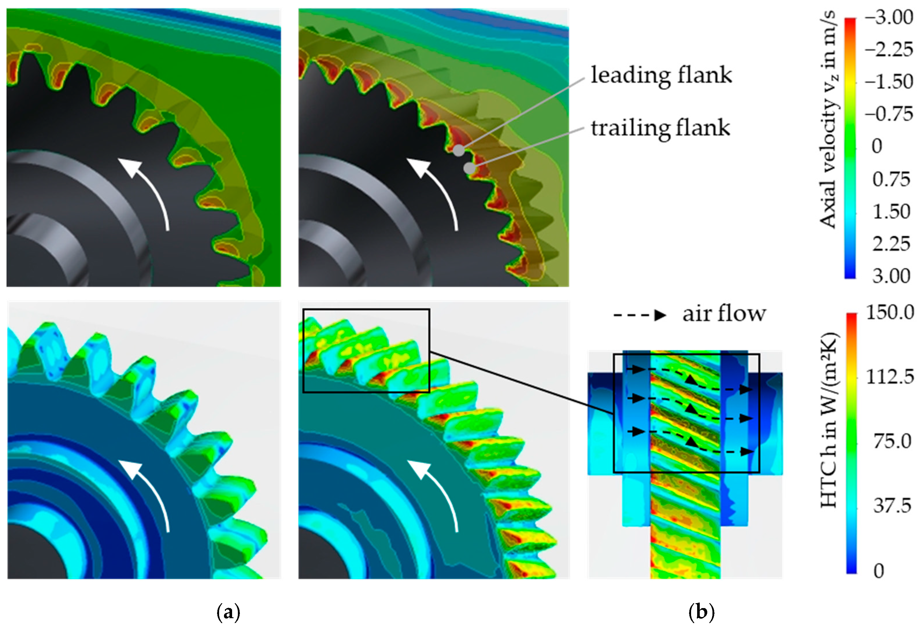
3.2.1. Local Heat Transfer Coefficient

Figure 7 shows the heat transfer coefficient h over the gear surfaces for the circumferential speeds vt = {2.0; 5.0; 10.0} m/s. It is visualized by the local coloring of the gear surfaces. Figure 7a refers to gear-C and in Figure 7b to gear-LL.
For both gears, HTC features the highest values on the tooth surfaces. The maximum values increase with circumferential speed. A comparison of the flow fields in Figure 5 with the HTC values in Figure 7 confirms that high HTC values are present in regions with distinct air flow and high flow velocity. Consequently, gear-C shows a symmetrical HTC distribution over the gear surfaces in the axial direction, with relatively low HTC values are shown in the middle of the tooth flanks. For gear-LL, the highest HTC values are predominant at the tooth tips on the front side of the gears. This indicates the strong influence of the interaction between the gear surfaces and the inflowing air on the HTC.

3.2.2. Influence of Flow Characteristics

Section 3.1 describes the flow characteristics of the different gears. The inflow of air to the gears takes place predominantly in the axial direction. In the following, the influence of the axial inflow of air to the gears on the heat dissipation from the gears is analyzed in detail. Therefore, the axial flow component in the z-direction is analyzed. Figure 8 visualizes the axial flow velocity (z-direction) on a plane congruent to the side surface of gear-C (a) and gear-LL (b) exemplarily for the circumferential speed vt = 10.0 m/s.
For gear-C, around the gears, a flow component directed to the center of the gears is present on the visualization plane, for example, in the surrounding yellow-colored regions. An axial flow out of the plane and away from the gears can be seen above the meshing area where the pinion and gear airflow encounter each other. This finding serves a deeper understanding of the flow field caused by gear-C described in Section 3.1. For gear-LL, a more distinct axial flow component near the teeth is present. Note that, in contrast to gear-C, no axial flow out of the plane is predominant over the meshing area. Instead, it is more pronounced near the housing walls of the gearbox, especially on the wheel side. These findings correlate with the conveying effect of gear-LL described in Section 3.1.
A more focused view on the axial flow velocity (z-direction) on a plane congruent to the side surface and the HTC between the gear surface and the air is presented in Figure 9 for the wheels gear-C (a) and gear-LL (b). Corresponding to the rotational direction, a leading and a trailing tooth flank are exemplarily marked in Figure 9b. For gear-C, a distinct axial air flow with relatively high velocity directed into the plane is predominant near the leading tooth flanks. In contrast, at the trailing tooth flanks, no distinct axial air flow is present. It appears that the trailing tooth flanks are rotating in the slipstream of the leading flank. Focusing on the HTC, a direct correlation of the local axial air inflow velocity and the HTC values is observed. Due to the distinct axial inflow of air to the leading tooth flanks, the side areas of the teeth show relatively high HTC values. The relatively low HTC values in the middle of the tooth flanks can be explained by a weak axial inflow of air in these areas.
For helical gear-LL, a distinct axial air flow into the plane is present near the teeth that extends over most areas of the tooth gaps. Comparably to gear-C, the leading tooth flanks show higher HTC values than the trailing tooth flanks. In contrast, relatively high HTC values are present in the middle of the trailing tooth flanks. This can be explained by the impingement of the axial air flow in these areas, as visualized in the complemented top view. Hereby, the axial flow is schematically visualized by black arrows. The results show that for gear-LL, more gear surface interacts with inflowing air compared to gear-C, especially at the tooth tips at the front side of the gears. Therefore, gear-LL has higher HTC values than gear-C.

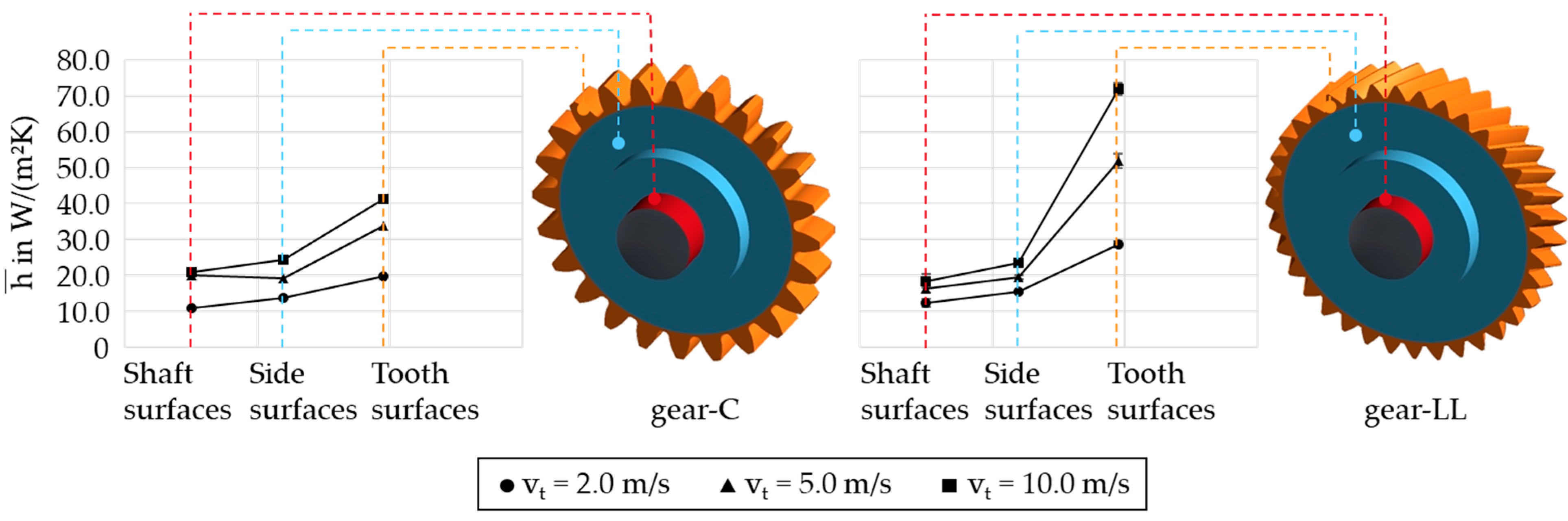
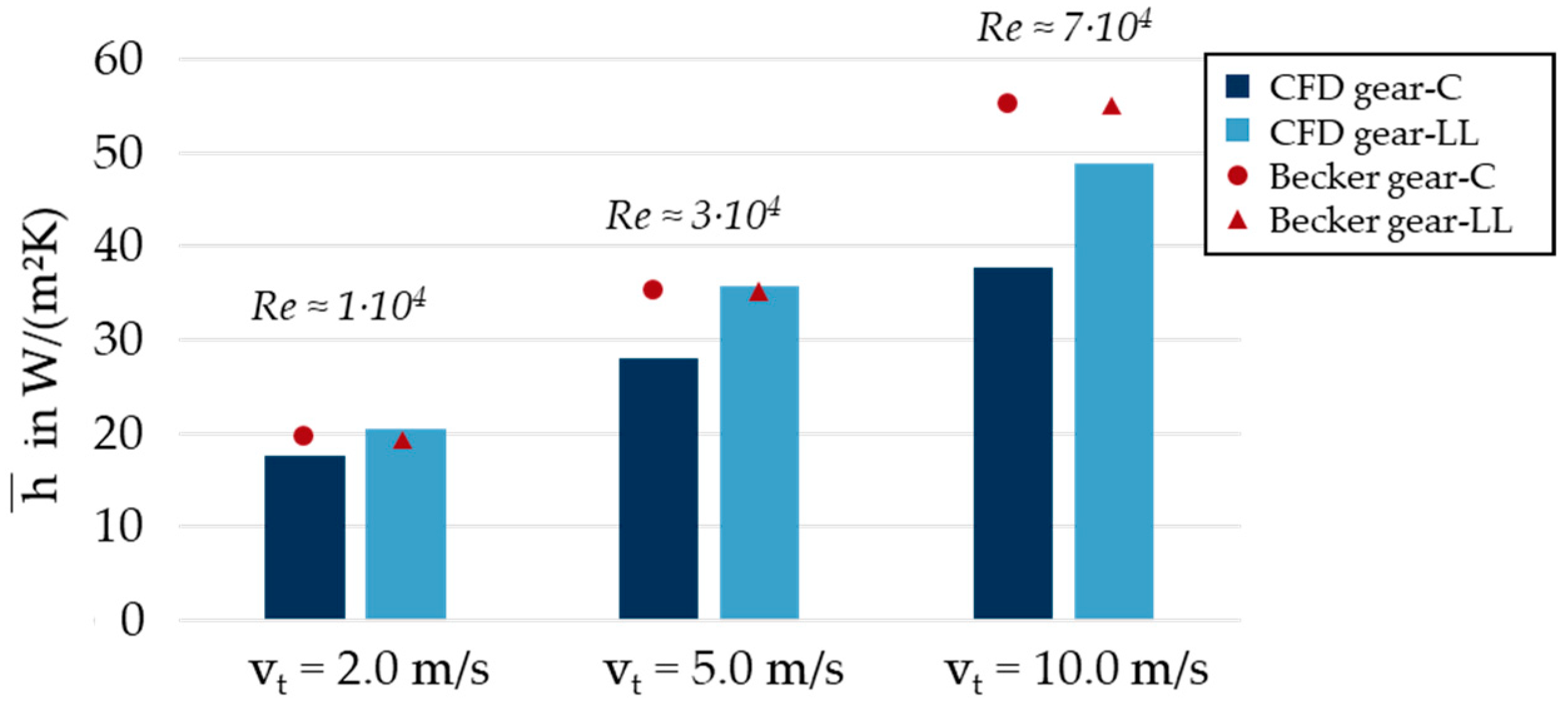
3.2.3. Surface-Averaged Heat Transfer Coefficient

Based on the results in Section 3.2.1, surface-averaged heat transfer coefficients h ¯ for the investigated gear geometries and circumferential speeds are evaluated. Figure 10 shows the surface-averaged HTC for the shaft, side, and tooth surfaces of the wheel of gear-C and gear-LL for the circumferential speeds vt = {2.0; 5.0; 10.0} m/s. They show an increase with vt. The tooth surfaces exhibit the highest values, followed by the side surfaces and the shaft surfaces. Thus, higher heat transfer coefficients are present for surfaces that lie further out on the gear in the radial direction. The comparison of gear-C and gear-LL shows, for the shaft and side surfaces, comparable surface-averaged HTC values for all circumferential speeds. In contrast, the surface-averaged HTC values for the tooth surfaces of gear-LL are significantly higher. This is in agreement with Section 3.2.2, according to which the helical gear-LL shows a more pronounced incident flow of the teeth.
In the following, the derived surface-averaged HTC values are classified in the state of the art. Figure 11 illustrates the overall surface-averaged HTC of the pinion and wheel for gear-C and gear-LL for the circumferential speeds vt = {2.0; 5.0; 10.0} m/s. For gear-LL, higher surface-averaged HTC values result for a given circumferential speed compared to gear-C. Figure 11 also shows the calculated HTC values based on the Nusselt correlation according to Becker [15], see Equations (2) and (3). The tip diameter was chosen as the reference length in accordance with Changenet et al. [17]. The underlying Reynolds number is within the given validity range of 103 < Re < 105. The analytical results predict the magnitude and trends over the circumferential speed in good agreement with the simulation results. With increasing circumferential speed, larger deviations can be noticed. Based on the Nusselt correlation, comparable HTC values are calculated for gear-C and gear-LL: The surface-averaged HTC value of gear-LL for the different circumferential speeds is only about 2.5% lower than that of gear-C, due to the smaller tip diameters of gear-LL. This demonstrates that the influence of the gear geometry and fluid flow on the HTC cannot be easily addressed by simple correlation analysis.
The results show that for circumferential speeds vt = 2.0…10.0 m/s, the surface-averaged HTC for the considered dry-lubricated gears can be classified in the range of h ¯ = 20…50 W/(m2K). This correlates with the magnitude of the HTC for solids and forced convection in gases specified by the VDI Heat Atlas [38]. The results of Lu et al. [14] showed that the HTC between gears and oil for a circumferential velocity of about vt = 30 m/s is of the magnitude of h ¯ = 400 W/m2K.

4. Conclusions

This study introduced and applied a consecutive simulation methodology for thermal CFD based on the FVM to investigate the heat dissipation of a dry-lubricated gear stage. Using the methodology developed, it was possible to investigate the influence of gear geometry and circumferential speed on the heat dissipation under atmospheric conditions. The sliding mesh method was used to model the gear kinematics, which was accompanied with a slight increase in the center distance. For sake of comparability, the same temperature boundary conditions were considered for both gear variants. The following conclusions can be drawn:
  • A circulating flow is formed in the gearbox due to the displacement of air by the gears and backflow to the gears.
  • Spur gears show a distinct radial displacement and a symmetrical axial backflow of air to the teeth. Helical gears show a distinct axial air flow due to conveying effects.
  • High heat transfer coefficients are particularly present on surfaces that interact strongly with air, e.g., on the leading tooth flanks.
  • Surface-averaged heat transfer coefficients show higher values for helical gears compared to spur gears.
  • The simplified Nusselt correlation can predict the order of magnitude of the simulated heat transfer coefficient as well as its trend over the circumferential speed.
  • The specific influence of gear geometry and the fluid flow on the heat transfer coefficient cannot be addressed by simple correlation analysis.
Future work may include iterative parameterization of thermal boundary conditions based on coupled finite elements calculations to determine component temperatures of dry-lubricated gearboxes and experimental validation. Furthermore, geometrical optimization measures can be investigated to improve heat dissipation and consequently to avoid thermal load limits. The developed simulation methodology can also be adapted to multiphase thermal CFD simulations to investigate oil-lubricated gearboxes.

Author Contributions

Conceptualization, L.H., C.P. and T.L.; methodology, L.H. and T.L.; software, F.D. and L.H.; formal analysis, L.H., C.P. and T.L.; investigation, F.D. and L.H.; resources, K.S.; writing—original draft preparation, L.H.; writing—review and editing, C.P., T.L. and K.S.; visualization, F.D. and L.H.; supervision, T.L.; project administration, K.S. All authors have read and agreed to the published version of the manuscript.

Funding

This research was funded by the research project STA 1198/17-2 of the priority program SPP 2074 II supported by the German Research Foundation e.V. (DFG). The authors would like to thank the DFG for the sponsorship and support received.

Institutional Review Board Statement

Not applicable.

Informed Consent Statement

Not applicable.

Acknowledgments

The authors gratefully acknowledge the LRZ for hosting the numerical calculations and Stefan Genuin for aiding the theoretical investigations and discussion.

Conflicts of Interest

The authors declare no conflict of interest.

Nomenclature

Notation
f ForcesN
n Vector orthogonal to surface-
q ϕ Source or sink of ϕ -
v Fluid velocitym/s
aCenter distancemm
bTooth widthmm
DReference lengthm
daTip diametermm
hHeat transfer coefficient│EnergyW/(m²K)│J
mnNormal modulemm
NuNusselt number-
PrPrantl number-
ReReynolds number-
SSurfacem2
tTimes
TTemperatureK
TMBulk temperatureK
u*Dimensionless velocity-
uτFriction velocitym/s
VVolumem3
vtCircumferential speedm/s
xCoordinate axism
y Distance from wall│Coordinate axism│m
y+Dimensionless distance-
zTooth number│Coordinate axis-│m
αPressure angle°
βHelix angle°
λThermal conductivity W/(mK)
νKinematic viscositymm2/s
ρDensity kg/m3
ϕ Generic quantity-
Indices
wallWall
refReference
oilOil
xDirection of x coordinate axis
yDirection of y coordinate axis
zDirection of z coordinate axis
simSimulation
1Pinion
2Wheel

References

  1. Lince, J.R. Effective Application of Solid Lubricants in Spacecraft Mechanisms. Lubricants 2020, 8, 74. [Google Scholar] [CrossRef]
  2. Quiban, R.; Changenet, C.; Marchesse, Y.; Ville, F. Experimental Investigations About the Power Loss Transition between Churning and Windage for Spur Gears. J. Tribol. 2021, 143, 205. [Google Scholar] [CrossRef]
  3. Liu, H.; Jurkschat, T.; Lohner, T.; Stahl, K. Detailed Investigations on the Oil Flow in Dip-Lubricated Gearboxes by the Finite Volume CFD Method. Lubricants 2018, 6, 47. [Google Scholar] [CrossRef] [Green Version]
  4. Höhn, B.-R.; Stahl, K.; Michaelis, K.; Otto, H.-P. Possibilities and Limitations for an Oil-Free Powertrain. In Proceedings of the 18th International Colloquium Tribology-Industrial and Automotive Lubrication, Ostfildern, Germany, 10–12 January 2012. [Google Scholar]
  5. Yilmaz, M.; Kratzer, D.; Lohner, T.; Michaelis, K.; Stahl, K. A study on highly-loaded contacts under dry lubrication for gear applications. Tribol. Int. 2018, 128, 410–420. [Google Scholar] [CrossRef]
  6. Sklenak, S.; Brimmers, J.; Brecher, C. Analyse der Wirkmechanismen im fluidfreien Wälzkontakt mit beschichteten Oberflächen. Forsch. Ing. 2022, 86, 357–366. [Google Scholar] [CrossRef]
  7. Simo Kamga, L.; Nguyen, T.-D.; Emrich, S.; Oehler, M.; Schmidt, T.; Gedan-Smolka, M.; Kopnarski, M.; Sauer, B. The effect of irradiated PTFE on the friction and wear behavior of chemically bonded PA46-PTFE-cb and PA66-PTFE-cb compounds. Wear 2022, 502–503, 204380. [Google Scholar] [CrossRef]
  8. Hofmann, S.; Yilmaz, M.; Maier, E.; Lohner, T.; Stahl, K. Friction and contact temperature in dry rolling-sliding contacts with MoS2-bonded and a-C:H:Zr DLC coatings. Int. J. Mech. Mater. Eng. 2021, 16, 9. [Google Scholar] [CrossRef]
  9. Bobzin, K.; Kalscheuer, C.; Thiex, M.; Stahl, K.; Lohner, T.; Maier, E.; Yilmaz, M. Adaptive (Cr,Al)N+Mo:Sg Coating for Highly-Stressed Contacts under Dry Rolling-Sliding Conditions. Tribol. Int. 2022, 174, 107761. [Google Scholar] [CrossRef]
  10. Handschuh, R.F. Test Facility Simulation Results for Aerospace Loss-of-Lubrication of Spur Gears; 2014. Available online: https://ntrs.nasa.gov/citations/20140017465 (accessed on 8 September 2022).
  11. Höhn, B.-R.; Michaelis, K.; Otto, H.-P. Flank load carrying capacity and power loss reduction by Minimized Lubrication. In Proceedings of the American Gear Manufacturers Association Fall Technical Meeting, Milwaukee, WI, USA, 17–19 October 2010. [Google Scholar]
  12. Yilmaz, M.; Önüt, A.; Lohner, T.; Stahl, K. Gear and bearing power losses: From dip to minimum quantity lubrication. ILT 2022. [Google Scholar] [CrossRef]
  13. Höhn, B.-R.; Michaelis, K.; Otto, H.-P. Minimised gear lubrication by a minimum oil/air flow rate. Wear 2009, 266, 461–467. [Google Scholar] [CrossRef]
  14. Lu, F.; Wang, M.; Pan, W.; Bao, H.; Ge, W. CFD-Based Investigation of Lubrication and Temperature Characteristics of an Intermediate Gearbox with Splash Lubrication. Appl. Sci. 2021, 11, 352. [Google Scholar] [CrossRef]
  15. Becker, K.M. Measurements of convective heat transfer from a horizontal cylinder rotating in a tank of water. Int. J. Heat Mass Transf. 1963, 6, 1053–1062. [Google Scholar] [CrossRef]
  16. Lebeck, A.O. Principles and Design of Mechanical Face Seals; Wiley: New York, NY, USA, 1991; ISBN 978-0-471-51533-3. [Google Scholar]
  17. Changenet, C.; Oviedo-Marlot, X.; Velex, P. Power Loss Predictions in Geared Transmissions Using Thermal Networks-Applications to a Six-Speed Manual Gearbox. J. Mech. Des. 2006, 128, 618–625. [Google Scholar] [CrossRef]
  18. Ayan, E.; von Plehwe, F.C.; Keller, M.C.; Kromer, C.; Schwitzke, C.; Bauer, H.-J. Experimental Determination of Heat Transfer Coefficient on Impingement Cooled Gear Flanks: Validation of the Evaluation Method. J. Turbomach. 2022, 144, 081008. [Google Scholar] [CrossRef]
  19. Paschold, C.; Sedlmair, M.; Lohner, T.; Stahl, K. Efficiency and heat balance calculation of worm gears. Forsch. Ing. 2020, 84, 115–125. [Google Scholar] [CrossRef] [Green Version]
  20. Paschold, C.; Sedlmair, M.; Lohner, T.; Stahl, K. Calculating component temperatures in gearboxes for transient operation conditions. Forsch. Ing. 2022, 86, 521–534. [Google Scholar] [CrossRef]
  21. Geiger, J.S. Wirkungsgrad und Wärmehaushalt von Zahnradgetrieben bei Instationären Betriebszuständen. Ph.D. Thesis, Verlag Dr. Hut, München, Germany, 2015. [Google Scholar]
  22. Hildebrand, L.; Dangl, F.; Sedlmair, M.; Lohner, T.; Stahl, K. CFD analysis on the oil flow of a gear stage with guide plate. Forsch. Ing. 2021, 30, 285. [Google Scholar] [CrossRef]
  23. Morhard, B.; Schweigert, D.; Mileti, M.; Sedlmair, M.; Lohner, T.; Stahl, K. Efficient lubrication of a high-speed electromechanical powertrain with holistic thermal managament. Forsch. Ing. 2020, 85, 443–456. [Google Scholar] [CrossRef]
  24. Maccioni, L.; Concli, F. Computational Fluid Dynamics Applied to Lubricated Mechanical Components: Review of the Approaches to Simulate Gears, Bearings, and Pumps. Appl. Sci. 2020, 10, 8810. [Google Scholar] [CrossRef]
  25. Shadloo, M.S.; Oger, G.; Le Touzé, D. Smoothed particle hydrodynamics method for fluid flows, towards industrial applications: Motivations, current state, and challenges. Comput. Fluids 2016, 136, 11–34. [Google Scholar] [CrossRef]
  26. Korsukova, E.; Morvan, H. Preliminary CFD Simulations of Lubrication and Heat Transfer in a Gearbox. In Volume 5B: Heat Transfer, Proceedings of the ASME Turbo Expo 2017: Turbomachinery Technical Conference and Exposition, Charlotte, NC, USA, 26–30 June 2017; American Society of Mechanical Engineers: New York, NY, USA, 2017; ISBN 978-0-7918-5088-6. [Google Scholar]
  27. Uerlich, R.; Koch, T.; Theising, H.; Eckstein, L. Method for thermal evaluation of automotive gearbox packages taking into account load point-dependent oil distribution. Automot. Engine Technol. 2022. [Google Scholar] [CrossRef]
  28. Fürstenberger, M.D. Betriebsverhalten Verlustoptimierter Kunststoffzahnräder: Verzahnungsverluste, Temperaturen, Tragfähigkeit und dynamisches Betriebsverhalten. Ph.D. Thesis, Techn. Univ., München, Germany, 2013. ISBN 978-3-8439-1228-0. [Google Scholar]
  29. Gersten, K. Einführung in Die Strömungsmechanik; Vieweg+Teubner Verlag: Wiesbaden, Germany, 1981. [Google Scholar] [CrossRef]
  30. Ferziger, J.H.; Perić, M.; Street, R.L. Computational Methods for Fluid Dynamics; Springer International Publishing: Cham, Switzerland, 2020; ISBN 978-3-319-99691-2. [Google Scholar]
  31. Liu, H.; Jurkschat, T.; Lohner, T.; Stahl, K. Determination of oil distribution and churning power loss of gearboxes by finite volume CFD method. Tribol. Int. 2017, 109, 346–354. [Google Scholar] [CrossRef]
  32. Liu, H.; Link, F.; Lohner, T.; Stahl, K. Computational fluid dynamics simulation of geared transmissions with injection lubrication. Proc. Inst. Mech. Eng. Part C J. Mech. Eng. Sci. 2019, 233, 7412–7422. [Google Scholar] [CrossRef]
  33. Schwarze, R. Mathematische Modelle einer Strömung. In CFD-Modellierung; Schwarze, R., Ed.; Springer: Berlin/Heidelberg, Germany, 2013; pp. 53–58. ISBN 978-3-642-24377-6. [Google Scholar]
  34. Gorla, C.; Concli, F.; Stahl, K.; Höhn, B.-R.; Klaus, M.; Schultheiss, H.; Stemplinger, J.-P. CFD Simulations of Splash Losses of a Gearbox. Adv. Tribol. 2012, 2012, 616923. [Google Scholar] [CrossRef] [Green Version]
  35. Yakhot, V.; Smith, L.M. The renormalization group, the ε-expansion and derivation of turbulence models. J. Sci. Comput. 1992, 7, 35–61. [Google Scholar] [CrossRef]
  36. Ansys. Fluent Theory Guide: Release 2020; ANSYS, Inc.: Canonsburg, PA, USA, 2020. [Google Scholar]
  37. Polifke, W. Wärmeübertragung: Grundlagen, Analytische und Numerische Methoden, 2nd ed.; aktualisierte Auflage; Pearson Studium: München, Germnay, 2009; ISBN 9783827373496. [Google Scholar]
  38. VDI-Gesellschaft Verfahrenstechnik und Chemieingenieurwesen. VDI-Wärmeatlas; Springer: Berlin/Heidelberg, Germany, 2013; ISBN 978-3-642-19980-6. [Google Scholar]
Figure 1. Considered test gearbox with gear-C (a) and gear-LL (b).
Applsci 12 10386 g001
Figure 2. Modular structure of the geometry model for gear-C (a) and gear-LL (b).
Applsci 12 10386 g002
Figure 3. Front view on the mesh model Meshgear-C (a) and Meshgear-LL (b).
Applsci 12 10386 g003
Figure 4. Simulation methodology for the thermal CFD simulations of the gearbox.
Applsci 12 10386 g004
Figure 5. Isothermal flow fields in 3D view and top view for vt = {2.0; 5.0; 10.0} m/s based on a steady-state calculation for gear-C (a) and gear-LL (b).
Applsci 12 10386 g005
Figure 6. Flow velocities vx and vy below the wheel of gear-C and gear-LL for vt = {2.0; 5.0; 10.0} m/s.
Applsci 12 10386 g006
Figure 7. Heat transfer coefficient h between the gear surfaces and air for vt = {2.0; 5.0; 10.0} m/s in 3D and top view for gear-C (a) and for gear-LL (b).
Applsci 12 10386 g007
Figure 8. Axial flow velocity (z-direction) on a plane congruent to the side surface for gear-C (a) and for gear-LL (b) at circumferential speed vt = 10.0 m/s.
Applsci 12 10386 g008
Figure 9. Detailed view on axial flow velocity (z-direction) and HTC between gear surface and air for the wheels of gear-C (a) and gear-LL (b) for vt = 10.0 m/s.
Applsci 12 10386 g009
Figure 10. Surface-averaged HTC h for shaft, side, and tooth surfaces for the wheel of gear-C and gear-LL for circumferential speeds vt = {2.0; 5.0; 10.0} m/s.
Applsci 12 10386 g010
Figure 11. Surface-averaged HTC h ¯ for gear-C and gear-LL for circumferential speeds vt = {2.0; 5.0; 10.0} m/s in comparison to HTC based on Nusselt correlation according to Becker [15].
Applsci 12 10386 g011
Table 1. Geometry of the considered gear-C and gear-LL.
gear-C
a in mmz1|2mn in mmαn in °β in °b1|2 in mmda1|2 in mm
Pinion (1)91.5164.520.001482.5
Wheel (2)24118.4
gear-LL
a in mmz1|2mn in mmαn in °β in °b1|2 in mmda1|2 in mm
Pinion (1)91.5242.7530.0262078.2
Wheel (2)36114.1
Table 2. Measured oil and component temperatures for different speeds at no-load [21].
vt in m/sToil in KTM1 in KTM2 in K
2.0303.25304.75304.85
5.0306.35309.05308.85
10.0313.55318.15317.55
Table 3. Properties of the considered mesh models Meshgear-C and Meshgear-LL (prism.: prismatic; hex.: hexahedral; tet.: tetrahedral).
Mesh ModelZonesElement Size in mmElement Number in MDensity in Elements per mm³
Meshgear-C(1) Gear zones0.75 (prism./hex.)222,3731.47
(2) Cylindrical zones1.00 (prism./hex.)784,7952.56
(3) Transition zones1.00 (hex.)79,0161.52
(4) Outer zone1.00 (hex.)810,4881.01
Overall Model0.921.89 1.33
Meshgear-LL(1) Gear zones0.75 (tet.)1,078,2046.17
(2) Cylindrical zones1.00 (prism./hex.)2,291,2042.42
(3) Transition zones1.00 (hex.)102,8661.52
(4) Outer zone1.00 (hex.)1,744,6301.01
Overall Model0.925.21 2.45
Table 4. Specifications of the prototypical conservation equation [33].
Equation ϕ D ϕ Q ϕ
Mass100
Impulse v · τ p + ρ g
Energyh · q p t + · ( τ · v )
Publisher’s Note: MDPI stays neutral with regard to jurisdictional claims in published maps and institutional affiliations.

