Article

Fatigue Reliability Design Method for Large Aviation Planetary System Considering the Flexibility of the Ring Gear

1
School of Mechatronics Engineering, Shenyang Aerospace University, Shenyang 110136, China
2
School of Mechanical Engineering and Automation, Northeastern University, Shenyang 110819, China
*
Author to whom correspondence should be addressed.
Appl. Sci. 2022, 12(20), 10361; https://doi.org/10.3390/app122010361
Submission received: 3 September 2022 / Revised: 3 October 2022 / Accepted: 11 October 2022 / Published: 14 October 2022
(This article belongs to the Special Issue Fracture & Failure Prevent: Reliability, Proactivity and Practice)

Abstract

:
As the foundation and core of various heavy aircraft transmission systems, the reliability level of large-scale aviation planetary mechanism restricts the economic affordability and service safety for the aircraft to a great extent. This paper takes the heavy helicopter planetary mechanism as the research object, and aims to improve the fatigue reliability level of the system. The fatigue load history of the gear teeth under the coupling of global elastic behavior of the system is calculated using a hierarchical finite element method, and the fatigue strength distribution of gear teeth is fitted based on the gear low circumference fatigue test with the minimum order statistics transformation method to provide cost-effective load and strength input variables for the system reliability prediction model. Based on this, a mapping path from the key structural elements of large-scale aviation planetary mechanism to the system reliability indexes is established, and then a new method of reliability-driven multi-objective optimization design for planetary mechanism structural dimensions is proposed. Finally, the influence law of ring gear rim thickness on the fatigue reliability of the planetary gear train is analyzed and the NSGA-Ⅱ genetic algorithm is used to determine the optimal stiffness matching result of the rim size of the designated type of large aviation planetary system. The stiffness potential of the core structural elements is maximized as a way to balance the contradiction between reliability and lightweight requirements of a large aviation planetary system.

1. Introduction

High-power transmission system technology is a core technology field for improving the performance of the heavy lift helicopter, reducing its noise and vibration levels, and controlling its life cycle cost [1]. Among the largest number of heavy lift helicopters currently in service, the large aviation planetary mechanism, as the basis and core of the transmission systems, determines the scientific and technological level of the transmission systems to a great extent, and is one of the bottlenecks restricting the development of transmission system technologies in the heavy lift helicopter [2].
As a deceleration terminal directly connected with the main rotor, the large aviation planetary mechanism is a power transmission link with the worst load environment and highest strength requirements in the heavy lift helicopter transmission system [3]. With the speed and bearing limits of the large aviation planetary mechanism continuing to break through, the structure and power sharing forms become more complex. These increase the complexity and uncertainty in structural strength design and analysis for the planetary system, and lead to a higher risk of structural failure when the new generation of heavy aviation planetary equipment pursues lightweight design [4]. Additionally, the transmission system is one of the three key dynamic systems in a helicopter. The reliability of its core link will directly determine the service safety and life cycle cost of the helicopter [5].
In terms of reliability analysis and modeling of gear transmission systems, Nejad [6] improved the ISO gear design specification, and proposed a tooth root bending fatigue damage analysis and modeling method for long-life large gears. Liu [7] established a dynamic reliability model for gear systems under part life correlation conditions to give the variation law of system fatigue reliability with time and part-life correlation degree. Li [8] proposed a generic modeling and simulation framework for the reliability assessment of gear systems. There are also some related works [9,10] that have carried out specific studies in terms of the relationship between systems and components, the way they achieve their functions, and temporal properties. The scholars have analyzed in detail the specificity of gearing in terms of system configuration, load transfer, and failure correlation from the perspective of reliability analysis and modeling. However, these current studies have heavily simplified the structural form of the gear system in reliability analysis processes, and it is difficult to reflect the way and degree of influence of the structural characteristics within the system on system reliability indexes.
The stress–strength interference theory is a basic tool for reliability analysis of mechanical structures [11,12,13,14]. Zhang [15] introduced an application of the stress–strength interference theory in fatigue reliability calculation for gear systems, and used the genetic algorithm to optimize the volume and reliability indexes for large-scale gear systems globally. During fatigue failure, the residual strength of a mechanical structure decreases continuously with the number of load actions, and the rate of strength decrease is directly related to the level of cyclic stresses [16]. In other words, for fatigue failure problems, the fatigue strength distribution at a specified life is a function of time and load, which is difficult to determine directly and efficiently by tests, whereas what is easily obtained directly by tests is the fatigue life distribution at a specified cyclic stress level [17,18]. It can be seen that it is also necessary to propose a mathematical tool capable of calculating fatigue reliability directly based on the life probability distribution in the framework of the stress–strength interference theory.
In a gear train, the failure of any one gear or gear tooth will affect the transmission capability of the entire system, so it is a common assumption in reliability analysis that a gear train is a series system with gears or gear teeth as basic functional units [19,20]. The loads on different individual gears in the system, or even different teeth of the same gear, may be different, but they all have a certain mathematical relationship with the system input power. As a key component carried by the planetary gear transmission system, the ring gear is simultaneously subjected to multiple meshing excitation sources, which causes it to become the main component of gear tooth cracks and fatigue damage in the planetary gear system. In addition, the deformation of the ring gear leads to the change in the meshing relationship of the gears in the planetary gear train. With the development of precision machinery, planetary gear transmission systems tend to be lightweight. To reduce the quality of the transmission system to meet the needs of the project, the thin-walled ring gear has gradually become popular for practical applications [21]. Wu and Parker [22] analyzed the inherent characteristics of the equidistant planetary gear flexible ring gear model by perturbation and a candidate mode method. Fan [23] calculated and analyzed the dynamic characteristics of the planetary gear transmission system considering the flexibility of the ring gear.
Tooth root bending fatigue strength is one of the most important strength check indexes in a high-speed and heavy-duty gear system. For the planetary mechanism in heavy lift helicopters, its extreme load conditions and harsh reliability requirements will put forward a higher standard for tooth root bending fatigue resistance. Another main method of tooth root bending stress calculation uses the general finite element tool [24,25,26]. However, the general finite element method has high computational cost in a model setting and solution operations, and is usually only suitable for isolated solutions of gear parts or several teeth, but it is difficult to perform global operations at the system level.
Providing strength variables for reliability prediction of the large-scale aviation planetary mechanism based on an effective test method is a necessary condition to ensure the analysis accuracy. From the perspective of the feasibility and economy of test implementation, in-depth analysis of the functional logic relationship between the tooth unit and the planetary system, and taking the bending fatigue test data of tooth structure as strength input variables for the system reliability model will be an effective way to realize the accurate prediction of fatigue reliability for this kind of large-scale high-end gear equipment. The double-tooth pulsating loading test using a high-frequency fatigue testing machine is one of the most common test methods to obtain the tooth bending fatigue strength [27,28,29]. The test method is simple to operate and has a high utilization rate for the sample, but it cannot simulate the time-varying and multi-axial stress states of the tooth root under actual working conditions, nor can it reflect the significant influence of lubricating oil on tooth bending fatigue strength. In fact, this method can be better applied to comparative analysis for gear performance parameters, but in the reliability prediction task of a gear system, the power flow closed gear rotation testing machine should be able to obtain more effective test results.
High reliability and long life have become the core technology development direction for future large aviation planetary mechanisms [30]. Compared to small and medium-sized helicopters, the heavy helicopter planetary mechanisms have larger component sizes, higher structural mechanical index requirements, and more demanding design standards for important geometric elements. In this paper, a heavy helicopter planetary mechanism is studied to improve the bending fatigue reliability level of the planetary wheel system. The fatigue load history of the gear teeth under the coupling of global elastic behavior of the system is calculated using the hierarchical finite element method, and the probabilistic fatigue strength of the gear teeth is fitted based on the gear low circumference fatigue test with the minimum order statistics transformation method to provide cost-effective load and strength input variables for the system reliability prediction model. Accordingly, a mapping path from the key structural elements of the large aviation planetary system to the system reliability indexes is constructed, and the stiffness requirements of the key structural features are included in the reliability indexes of the planetary wheel system, forming a new method for reliability-driven multi-objective optimal design of the structural dimensions in planetary mechanisms. This method can provide targeted structural optimization guidance in the development and design for the large aviation planetary system, and significantly reduce the cost of the reliability index realization for this kind of large-scale high-end equipment in design iteration processes. At the same time, it can provide important reference data for the first renovation period of relevant finalized products and then provide the technical support for their economic guarantee in the whole life cycle.

2. Calculation Method of Tooth Root Stress Based on Hierarchical Finite Element Technique

The urgent need for the lightweighting of the new generation of large aviation planetary equipment has led to the widespread adoption of lighter and thinner structural design forms for its components [21]. The introduction of a large number of such flexible features means that large components such as drive spindles and support frame bodies will undergo significant elastic deformation under heavy loads. The resulting stiffness problem makes the accurate calculation of tooth root stresses necessary to fully consider the nonlinear mechanical behavior of the entire system in terms of elastic deformation, meshing misalignment, etc. In the face of mechanical simulation analysis tasks of large complex gear systems, the general finite element method has the contradiction between computational accuracy and computational cost. In order to solve the contradiction, this paper proposes an advanced hierarchical finite element method for tooth root stress analysis of large aero-planetary mechanisms, which is directly based on a detailed 3D finite element sub-model of the gear teeth when performing tooth root stress calculations. In the system-level model, the time-varying load lines on tooth surfaces can be obtained by quasi-static mechanical analysis and then loaded onto the tooth surfaces of the finite element sub-model as the load boundary conditions. At the same time, the system elastic deformation results are extracted and loaded into the finite element sub-model as displacement boundary conditions, so that the effects of elastic deformation and meshing misalignment of the whole system are naturally included in the tooth root stress calculation results of the sub-model.
There is no need to perform detailed tooth root stress calculations in the system-level model, which results in significant savings in computational costs for system-level analysis. The physical effects such as rotation and offset of the drive components are already considered in the quasi-static analysis results of the system-level model, so the boundary conditions imposed in the secondary sub-model are also relatively simple. Faced with the task of tooth root stress analysis of large aero-planetary systems, the analysis efficiency of the hierarchical finite element method will also be much higher than that of the general finite element method, considering only the convenience of modeling and boundary condition setting. In addition, unlike commercial finite element software that uses nonlinear equation solvers, the hierarchical finite element method uses an improved simplex solver to ensure convergence within a set effective number of iterations. Although the total number of degrees of freedom in the two-level finite element models can be very large, this hierarchical analysis means can still keep the amount of CPU time and memory required for computing within the capabilities of an ordinary computer (ordinary home version of a computer). In this paper, the structural details and material properties of a certain type of large-scale aerospace planetary mechanism will be used as a reference, and its high-fidelity mechanical simulation model will be constructed by the hierarchical finite element method. Accordingly, the tooth root hazard stress histories of the system under quasi-static elastomechanical behavior is calculated to provide effective load input variables for the system fatigue reliability assessment model.

2.1. Simulation Modeling of System-Level Elastic Mechanics Behavior

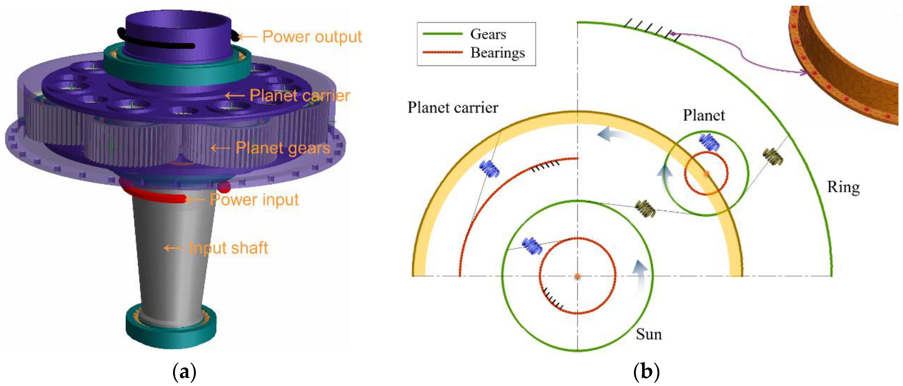
The system-level elastomechanical simulation model of a large aero-planetary mechanism is constructed by the semi-analytic finite element technology. This is used to accurately evaluate the elastic deformation of large thin-walled parts in the system and the meshing misalignment between gear teeth, and to provide detailed load and displacement boundary conditions for the secondary sub-model of tooth root stress analysis. The overall configuration of the system model of the planetary mechanism is shown in Figure 1a; all the planetary gears are uniformly distributed on a planet carrier along the circumference, and the specific structural parameters of the planetary gear system are shown in Table 1. The power flow path inside the mechanism starts from the input shaft, and passes through the sun gear and the planet gears to the planet carrier, which finally transmits the motion and power to the main rotor shaft after a 3.3 times deceleration. Among them, the input shaft is mechanically described in the form of Timoshenko beams, realistically reproducing its mass distribution and stiffness distribution, taking into account the necessary properties of the degrees of freedom such as torsion, axial, and bending. Finite element modeling is used for large thin-walled parts such as the planet carrier and ring gear to express their degree of freedom properties in a fully flexible setting. In addition, without considering the elastic deformation of the reducer box, the inner and outer rings of each bearing are assumed to be rigid bodies, i.e., they will not be deformed by the load and can only move or tilt as a whole. The input shaft is supported by two tapered roller bearings (TRB) in an O-shaped layout, whose outer rings are rigidly connected to the box. Double-row tapered roller bearings (DRTRB) with X-shaped layout are assembled inside each planet gear, and the inner ring of the bearing is rigidly connected to the planet carrier. A radial ball bearing (RBB) fixes the planet carrier and makes it have a small floating amount to offset the behavior of unequal load sharing among planet gears to some extent, and its outer ring is rigidly connected with the box, and the structural parameters of various types of bearings are shown in Table 2. In the system model, the gear meshing stiffness and the bearing support stiffness are characterized by spring properties, and the system degrees of freedom are set as shown in Figure 1b. In addition, the rated working parameters of the planetary mechanism mainly include input power of 5000 kW, input speed of 500 rpm, and operating temperature of 70 °C.
The positioning and assembly for various transmission components is carried out in the RotationMaster (RM) software platform, which is an advanced simulation platform for comprehensive analysis and calculation of complex transmission systems directly, and is now widely used in engineering fields such as aviation and automotive. The tolerance search technology of RM is used to filter out the connection node groups of components, and control parameters such as search criteria and selection methods are jointly adjusted to establish the node rigid connection for finite element components. Subsequently, the finite element models in the system are deflated to extract the corresponding mass and stiffness matrices. Meanwhile, the deformation smoothness is used as an evaluation index to examine the performance of each stiffness matrix with the help of the load transfer behavior among condensation nodes. Finally, load boundary conditions are applied to the system model and quasi-static elastic mechanical behavior global operations are performed on it, with the aim of obtaining the node displacement response of each elastic member and the tooth surface time-varying load line results to provide displacement and load boundary conditions for the secondary sub-model of tooth root stress analysis.

2.2. Modeling of Deformable Parts

2.2.1. Deformable Planet Carrier

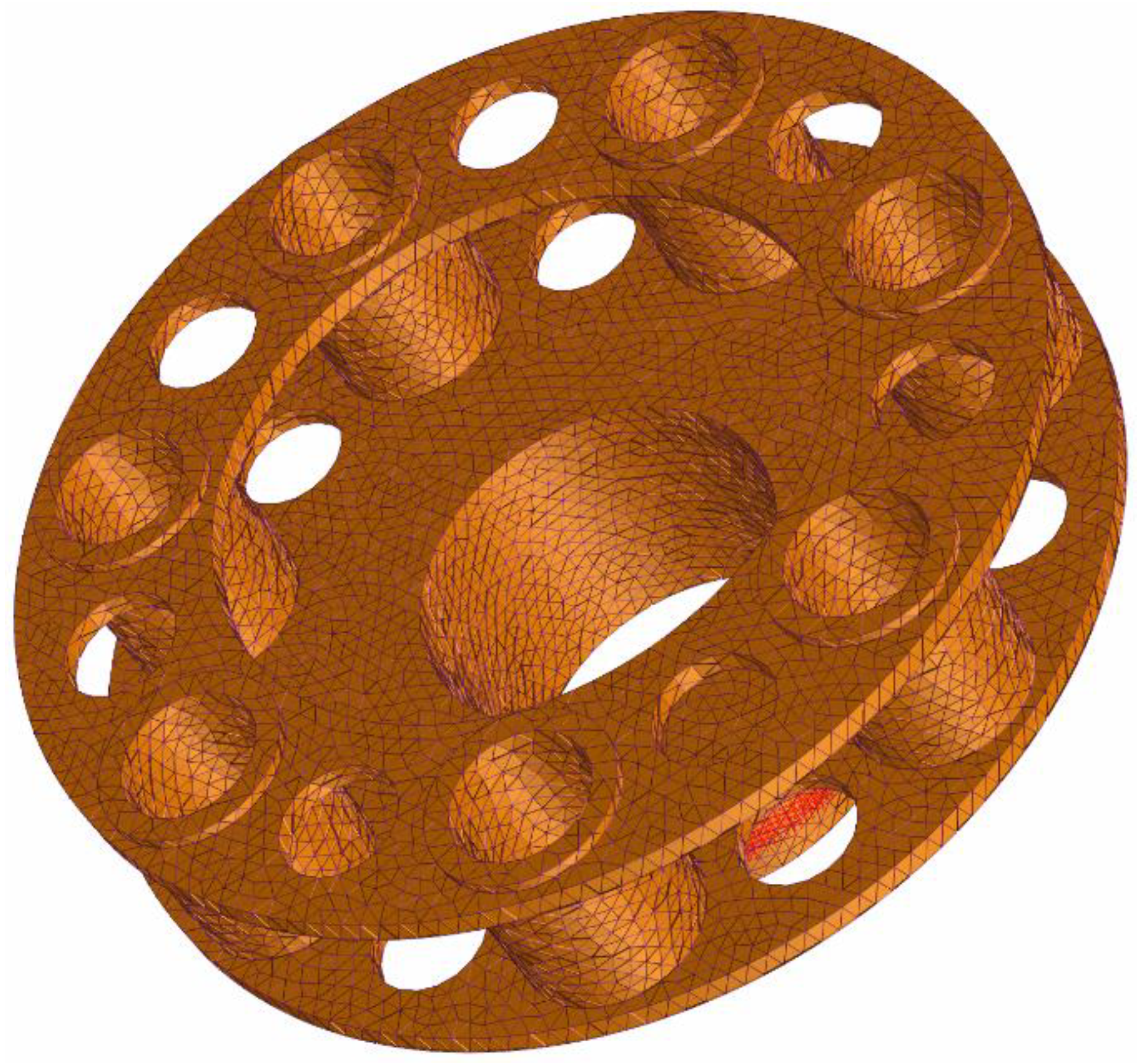
An FE model and geometry of a planet carrier is illustrated in Figure 2, which shows an example of an FE grid for a seven planet system with its supporting conditions simulated by lumped stiffness elements. Since there are no relative displacements between the axis of rotation of the planet pins and the planet nodes (planet centers), a fixed interface component mode synthesis method can be used to reduce the size of the carrier model. The stiffness of the springs is considered to be significantly higher than that of the bearings and pins, thus creating a rigid link in the radial directions between the contour nodes and planet centers. The classic reduction process of Craig and Bampton [31] is employed in which displacements are expressed in terms of static and dynamic modes as
X PCint X PCbou = ϕ D ϕ S 0       I · q PC X PCbou
with X PCint , vector of the internal degrees of freedom, X PCbou , vector of the degrees of freedom at the contour nodes, ϕ D , truncated modal matrix of the fixed-interface planet-carrier structure, ϕ S , static mode matrix, I , identity matrix, 0 , nil matrix, and q PC , vector of the planet-carrier modal unknowns.

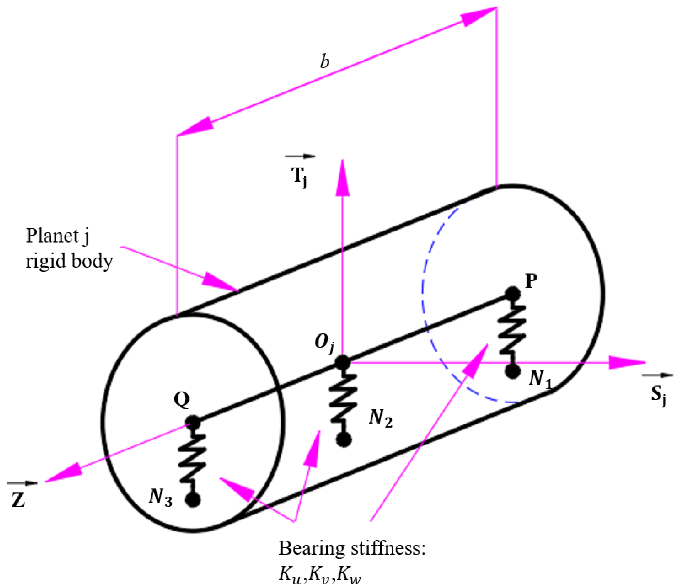
2.2.2. Planet Bearing Element

This connecting part is composed of seven lumped spring elements across the planet bore in order to connect node Oj of planet j to the corresponding three contour nodes of the planet-carrier substructure (denoted N1, N2, and N3 in Figure 3). Planets are modeled as rigid disks with 6 degrees of freedom (DOFs) which are the infinitesimal generalized displacements superimposed on rigid-body motions and represented by screws of coordinates.
τ j u j O j = v j S j + w j T j + u j Z ω j = φ j S j + ψ j T j + θ j Z
where Sj, Tj, and Z are the unit vectors of the frame fixed to the sun gear/planet j mesh (Figure 4).
Considering two points P and Q belonging to planet j, their displacements are expressed using the shifting property of the moment of screw τ j as
u j ( P ) = u j ( O j ) + P O j × ω j u j ( Q ) = u j ( O j ) + Q O j × ω j
Denoting Kv, Kw, and Ku the stiffness in the Sj, Tj, and Z directions between P and N1, Oj, and N2, and Q and N3, the strain energy stored in the spring element 1 connecting node N1 and point P reads
U 1 = 1 2 X T K u V u · V u T + K v V V · V V T + K W V W · V W T X = 1 2 X T K 1 X
where X T = ( u j , v j , w j , φ j , ψ j , θ j , u N 1 , v N 1 , w N 1 ) is the vector containing the degrees of freedom associated with nodes Oj (6 DOFs) and N1 (3 DOFs). The structural vectors
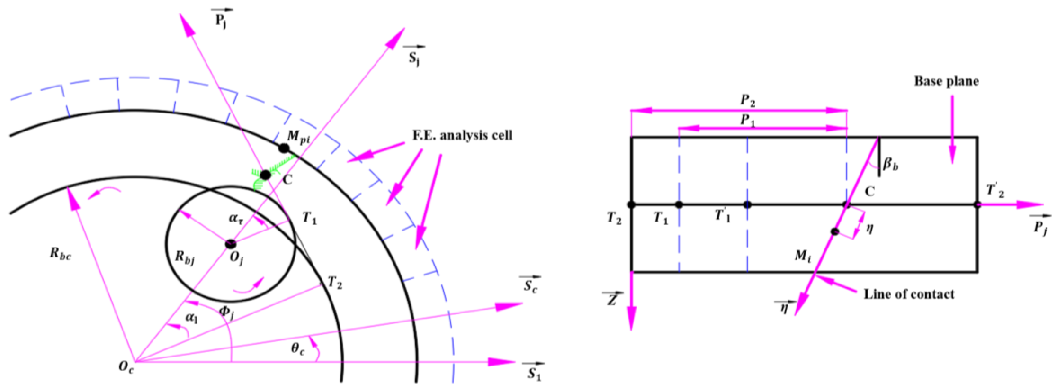
 Vu, Vv, and Vw are expressed in terms of the planet width and its angular position Φ j (Figure 4) as
V u T = 1 , 0 , 0 , 0 , 0 , 0 , 1 , 0 , 0 V v T = 0 , cos Φ j , sin Φ j , b 2 sin Φ j , b 2 cos Φ j , 0 , 0 , 1 , 0 V w T = 0 , sin Φ j , cos Φ j , b 2 cos Φ j , b 2 sin Φ j , 0 , 0 , 0 , 1
A similar procedure is used for the other spring elements attached to the same planet, thus leading to the 15 × 15 stiffness matrix of the planet j bearing element which connects the 6 degrees of freedom at the planet center Φ j ( u j , v j , w j , φ j , ψ j , θ j ) and those at nodes N1(uN1, vN1, wN1), N2(uN2, vN2, wN2), and N3(uN3, vN3, wN3).

2.2.3. Deformable Ring Gears

Ring gears and their supports are modeled by using FE analysis combined with lumped parameter elements to account for the ring-gear bearing stiffness and for the contribution of the teeth modeled as lumped masses. The ring-gear FE model is reduced using a component mode synthesis method based on the mode shapes of the undamped isolated structure. After separating the internal displacements, X RGint and the degrees of freedom at the boundary nodes, X RGbou , i.e., on the root cylinder and in correspondence with the planet ring-gear contacts, the following approximation is used:
X RGint X GDbou = Φ N q RG
with X RGint , vector of the internal degrees of freedom, X RGbou , vector of the degrees of freedom at the contour nodes, Φ N , truncated modal matrix of the undamped ring-gear structure, and q RG , vector of the modal unknowns.

2.3. Construction of a Secondary Sub-Model for Tooth Root Stress Analysis

In the system-level model, the time-varying load lines on tooth surfaces are obtained by quasi-static mechanical analysis, and they are loaded on the tooth surfaces of the secondary sub-model as load boundary conditions. At the same time, the system elastic deformation results are extracted and loaded into the sub-model as displacement boundary conditions, so that the effects of elastic deformation and meshing misalignment of the whole system are naturally included in the tooth root stress analysis results of the sub-model. In addition, dynamic behavior factors such as gear rotation and meshing are also considered in the system model, and when these key factors are fully expressed in the system model, the overall structure of the sub-model can be considerably simplified. It can contain only a number of teeth and corresponding rim features (the overall configuration is shown in Figure 5c), and its modeling and computational costs will be more focused on the geometric details of tooth roots. In terms of model quality, the sub-model is more comprehensive than the system model in terms of tooth root geometric elements, and its accuracy level, mesh quality, and other quality indicators are higher.
The secondary sub-model of tooth root stress analysis with high fidelity is established by a general finite element method. The parametrically defined detailed gear solid models in the system level model are as auxiliary modeling elements for the 3D finite element sub models, which solves the problem of difficult modeling for the general finite element method to a certain extent. In addition, in order to further alleviate the contradiction between calculation accuracy and operation speed, a first-order hexahedron element is adopted in the finite element sub-model. When meshes are relatively coarse, tooth top may appear “jagged” in appearance due to shear self-locking or hourglass effect from the first-order element, but this does not affect the analysis results of tooth root stress. The RM software platform here can recommend an economical adaptive mesh density that can be used to accurately capture the steep stress gradients at the root of teeth and is sufficient to allow the sub-model calculations to converge within an effective predetermined number of iterations. In the system-level analysis, the meshing forces on gear teeth are applied through the superconstriction nodes; whereas in the secondary sub-model, the meshing forces are applied by the tooth surface load lines obtained from the system-level analysis, which is a clear difference in the setting of the load boundary conditions between the two.
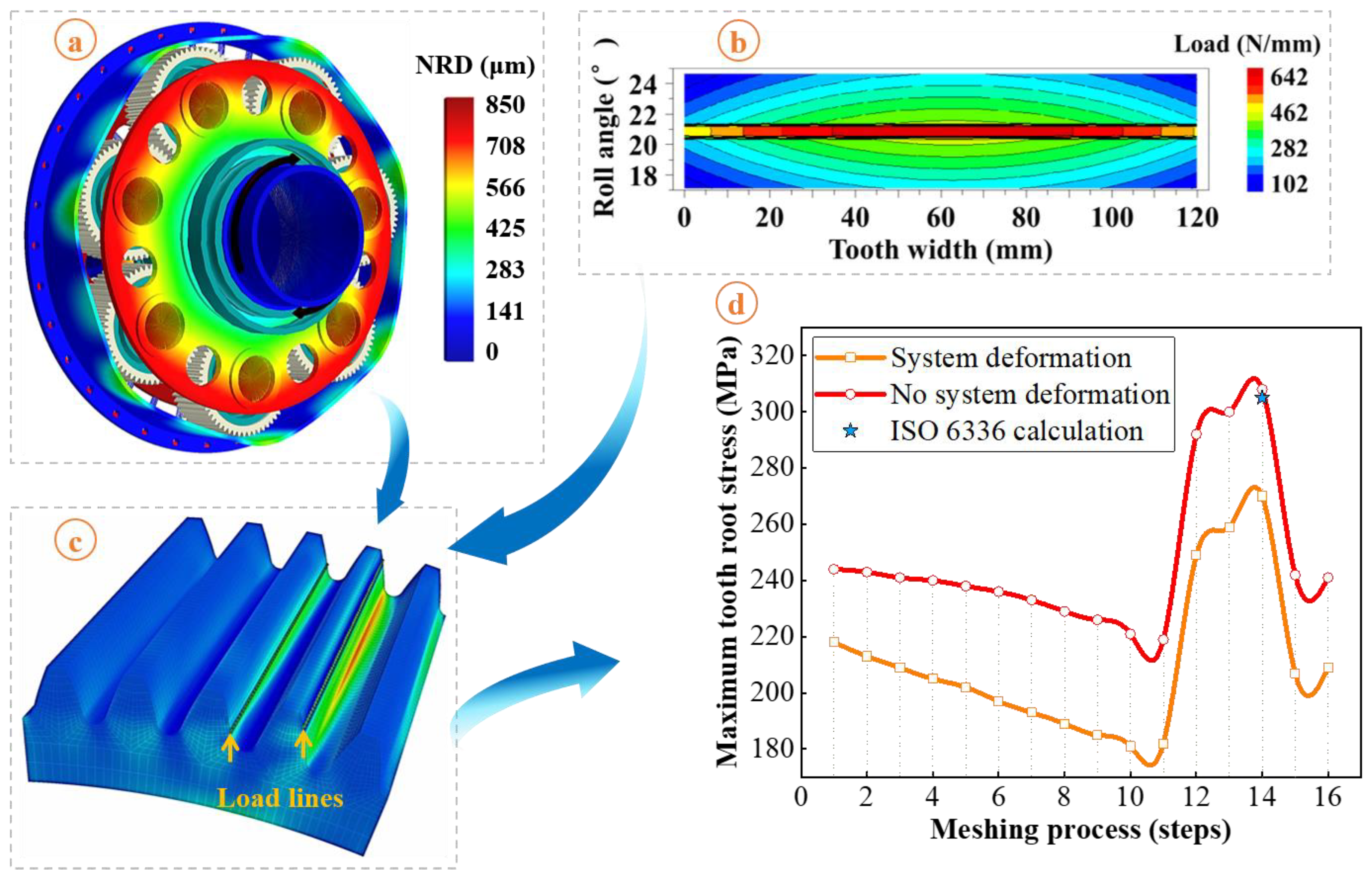
Taking the sun gear as an example, the tooth root stress analysis program of its sub-model is run, and the maximum principal stress values of tooth roots are calculated according to the first strength theory. The calculation results of the system elastic deformation and tooth surface load lines are applied to the sub-model as input conditions, as shown in Figure 5, and the sub-model is subsequently solved according to the set rotation steps. According to the coincidence degree of the gear pair in the system, the meshing in and meshing out processes of gear teeth is divided into 16 rotation steps, and the sub-model performs a finite element solution for each step of the gear tooth revolution. Although this makes the stiffness decomposition and load vector inverse substitution process relatively complex (involving multiple recursive traversals at the substructure level), this significant reduction in computational cost by appropriately increasing the complexity of the procedure is worthwhile. Figure 5d shows the calculated tooth root stress history for the sun gear teeth at 16 rotation steps; from 12 to 14 steps the teeth are in single tooth engagement and the corresponding root stress values are higher. Under the assumption of complete rigidity of the system (i.e., without inputting the system elastic deformation results into the finite element sub-model), the tooth root stress simulation results are 11.9–12.3% higher than those with the system deformation taken into account, indicating that ignoring the flexible behavior characteristics of large aero-planetary mechanisms may directly lead to overly conservative design solutions for the corresponding structural strength. In addition, the stress result obtained by the calculation method of tooth root bending stresses in the international standard ISO 6336 is also marked in Figure 5d, and the corresponding calculation model is as follows:
σ F = F t b · m · K A · K V · K F β · K F α · Y F · Y S · Y β · Y B · Y D T
The simulation results without considering the elastic deformation of the system are in perfect agreement with this result (which also does not fully consider the deformation of the system), which proves to a certain extent the validity of the load boundary conditions and other model parameter settings during the simulation analysis.

3. Tooth Probability Strength Fitting Based on Gear Fatigue Test

3.1. Gear Bending Fatigue Test

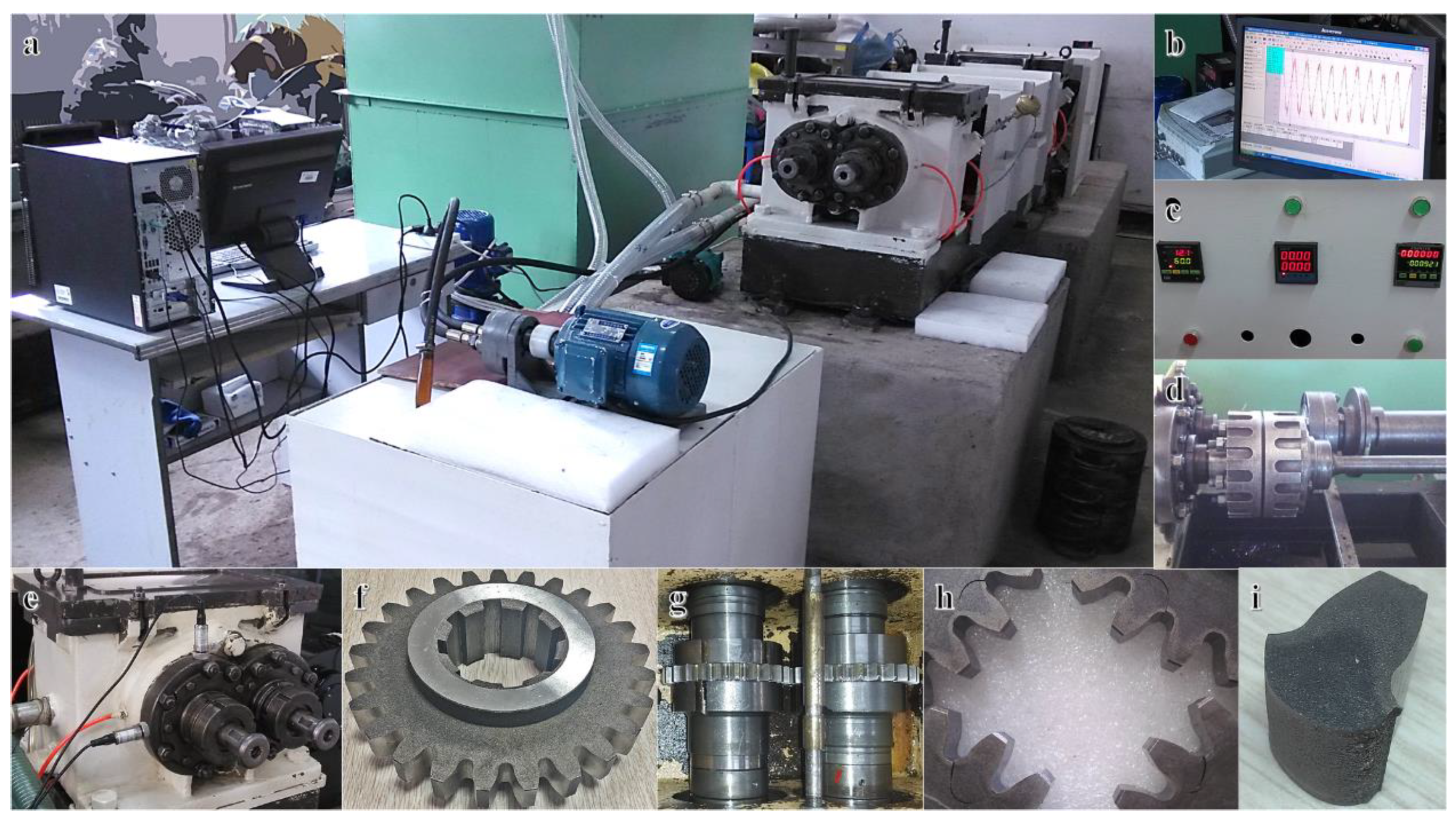
The gear bending fatigue accelerated life test is carried out by the power flow closed gear rotation testing machine, which provides strength information for the fatigue reliability prediction model of the large aviation planetary system. The overall layout of the test platform is shown in Figure 6a, and its working principle and calibration criteria are detailed in the previous related research work [2]. The power flow input to the tester uses a conical friction surface type mechanical loading device, as shown in Figure 6d, which ensures reliable closure of the power flow at high circumferential cycles (>107). The top view of the test gearbox interior is shown in Figure 6g. The gear pair is assembled in the form of full tooth width contact, and the lubrication and cooling for the gear pair are realized by oil injection during the test. The threshold value of the vibration monitoring system (see Figure 6b,e) is adjusted according to the predetermined failure state of the gear specimen, so that the tester is equipped with an autonomous stop function in case of sudden tooth fatigue breakage. The technique better ensures the consistency of the failure state of all gear specimens, as shown in Figure 6h, where the final shape and size of each tooth root crack are essentially the same. The fatigue fracture morphology of the tooth root is shown in Figure 6i, and the macroscopic morphological features of the fatigue extension and transient fracture areas can be clearly seen.
The structural details and parameters of the gear specimens are shown in Figure 6f and Table 3, respectively. The bending fatigue strength of the gear teeth of the specimens is used to simulate the strength of the gear teeth of actual service gears, providing direct strength input variables for the planetary system reliability model. In order to make the stress state at the gear teeth root of the specimens the same as that of the service gears, the geometrical parameters of the gear teeth of the specimens are made as identical as possible to those of the service gears as well as the overall parameters of the specimens being made equal or similar to the service gear parameters in terms of material properties, machining, and heat treatment, etc. The effective assurance of these approximations will help to improve the prediction accuracy of the fatigue reliability index of the planetary system. In addition, it is assumed that the tooth root bending fatigue fracture starts at the point of maximum tooth root stress (middle of tooth width), i.e., the dimensional effect in the direction of tooth width of the spur gear is ignored, whereby the tooth width of the specimens can be reduced to control test cost. All gear specimens are from the same batch production process to minimize the dispersion of test data.

3.2. Tooth Probability Strength Fitting

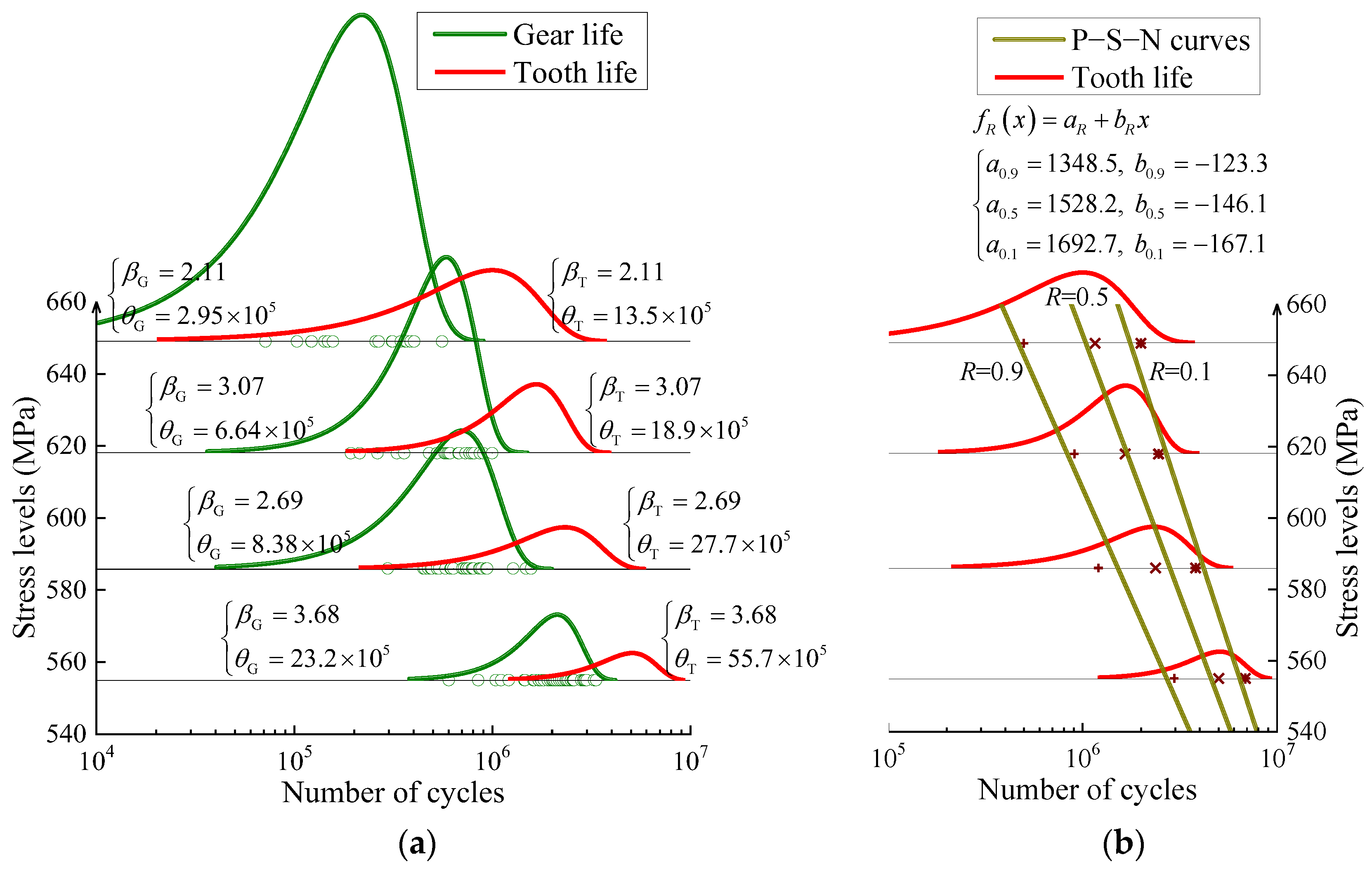
Tooth root stress peak is used as an evaluation index for stress grade, and the bending fatigue performance of tooth root is tested by the group method under four stress grades. The selected stress levels and the number of test points under various stress levels are 649 MPa (17 points), 618 MPa (22 points), 586 MPa (29 points), and 555 MPa (38 points). During the test, if any tooth on the gear sample fails first, the testing machine will automatically stop, and the direct data obtained from this is gear life rather than tooth life. It represents the ability of the individual gear to maintain excellent transmission function under current stress level, so gear life is also “first broken tooth” life. From the perspective of probability, the more teeth on a gear, the more potential for failure links. Therefore, under the same stress and revolution conditions, the failure risk of the gear will increase with the increase in the number of teeth. In the process of this test, a complete rotation of the sample is recorded as one gear life. In this conventional counting mode, the statistical characteristics of the number of teeth lead to the difference in the probability life between the gear and tooth. In order to obtain direct strength input variables for the reliability prediction model, a probabilistic statistical transformation method is proposed to fit tooth P−S−N curves based on gear life data.
The probability life relationship between the gear and tooth is established based on the concept of minimum order statistics. The fracture of any tooth on a gear will cause the gear to lose excellent transmission capacity. For this reason, it can be considered that the life of a gear depends on the minimum life of its teeth. Suppose X 1 ,   X 2 ,   ,   X n is a set of samples from a parent X, then X min = min X 1 ,   X 2 ,   ,   X n is the minimum order statistics of the parent. This probability model will be applied to the life transformation calculation under the failure mode of tooth root bending fatigue, then gear probability life is equal to the minimum order statistics of tooth probability life.
Assuming that the cumulative distribution function of random variable X is F x and its probability density function is f x , then the probability density function of the minimum order statistics of X can be expressed as
g min x = z · 1 F x z 1 · f x
where z indicates the number of gear teeth.
If the two-parameter Weibull distribution is adopted to express tooth probability life, then the cumulative distribution function can be expressed as
F x = 1 exp x / θ β
and the probability density function is
f x = β · x β 1 / θ β exp x / θ β
where β and θ is respectively the shape parameter and scale parameter of the tooth life distribution.
Equations (9) and (10) are brought into Equation (8) to obtain the following equation:
g min x = β · x β 1 / θ / z 1 / β β exp x · z 1 / β / θ β
If the number of teeth on a gear is z, then g min x directly represents the probability density function of gear life distribution. From the expression of this function, it can be seen that the gear probability life also follows two-parameter Weibull distribution, and the shape parameter and scale parameter are as follows:
β Gear = β θ Gear = θ / z 1 / β
In statistical processing for test data, the two-parameter Weibull distribution function is adopted to fit the probability distribution of gear life points under each stress level. The probability life transformation between the gear and tooth is then performed by Equation (12). Finally, a least square method is used to linearly fit the same probability quantiles of the tooth life distribution under each stress level in a single logarithmic coordinate system, and the results of tooth bending fatigue P−S−N curves obtained are shown in Figure 7. Under deterministic loading, the dispersion of fatigue life generally increases as stress level decreases; therefore, in a linear coordinate system, the P−S−N curve family will appear as an “umbrella” shape with a small upper opening and a large lower opening. However, due to the single logarithmic coordinate system, the curve family presents a corresponding inverted shape.

4. System Reliability Modeling Considering Planetary Transmission Behavior Characteristics

4.1. Conditional Probability Expectation Algorithm for Part Fatigue Reliability Calculation

The traditional “load and strength interference” analysis method is extended to establish a conditional probability expectation algorithm for calculating the fatigue reliability of parts based on the probability distribution of stress level and the life distribution under specified stress level. For the static strength failure of parts under one load, the reliability can be regarded as a function of stress, and the conditional reliability model under specified stress is established. That is, under the condition of stress σ , the probability calculation formula of static strength S greater than the stress is
ζ σ = σ f S d S
where f S is the probability density function of static strength S.
Furthermore, the static strength reliability model of parts that can reflect the effect of load uncertainty can be expressed as
R = 0 h σ · ζ σ d σ
where h σ is the probability density function of stress σ .
Equation (14) is the traditional “load and strength interference model”, then the basic meaning is extended from probability perspective. Based on the total probability calculation principle of continuous random variable, Equation (14) can be interpreted as the mathematical expectation of random function ζ σ in the definition domain of random variable σ .
For fatigue reliability, because it is difficult to obtain the fatigue strength distribution under specified life directly, a mathematical expression for calculating the fatigue reliability of parts directly based on life distribution can be constructed according to the above extended thinking. Assuming that ζ n , σ is the conditional fatigue reliability function under specified stress level, that is, under the condition of stress level σ , the probability calculation formula of the life N greater than the number of load cycles n is
ζ n , σ = n f N σ d N
where f N σ is the life probability density function at stress level σ .
Correspondingly, under the action of random stress level σ , the fatigue reliability model of parts can be expressed as
R n = 0 h σ · ζ n , σ d σ
The fatigue reliability index of parts under random constant amplitude cyclic load can be directly calculated by Equation (16).

4.2. Fatigue Reliability Evaluation Model of Series System Considering Failure Dependence

The fracture of any tooth in a planetary system will affect the transmission capacity of the whole system. Therefore, if each tooth in the system is regarded as a potential failure unit, then the system is a typical series system. In service process, the load borne by each tooth has significant dependence with the system input power, and the load dependence and general load randomness make the failure of each element not independent of each other, so the reliability of the series system cannot be simply considered as the reliability product of each unit.
The fatigue reliability evaluation model of a series system is established based on conditional probability expectation algorithm and considering the failure dependence among unit parts. First, only under the action of the deterministic load is the failure of each part in the system independent of each other, so the conditional reliability of the series system is equal to the conditional reliability product of each part. Then considering load uncertainty effect at the system level, the probability that r parts in the system will not fail, that is, the fatigue reliability evaluation model of the series system, is
R SYS n = 0 h 0 σ i = 1 r n f i N s i σ + μ i d N d σ
where h 0 σ is the probability density function of standard normal distribution, and f i N s i σ + μ i is the life probability density function of the ith part under stress level s i σ + μ i .
The model assumes that the load follows normal distribution, and realizes load normalization for each part through the mathematical relationship transformation between normal distribution and standard normal distribution, so as to consider the load uncertainty effect at system level.

4.3. Structural Optimization of Reliability Model Considering Sequence Characteristics of Planetary System

The kinematic equation of planetary transmission is deduced according to a periodic operation law in the planetary gear train, at the same time, the single tooth meshing times of various gears in the system within the same time interval are obtained, which will match sequence characteristic attributes for system fatigue reliability evaluation model. Assuming that the absolute angular velocities of the sun gear, planet gear, ring gear, and planet carrier are ω S , ω P , ω R , and ω C respectively, then the mathematical relationship among them can be expressed as
ω S = i SR C · ω R + i SC R · ω C ω R = i RS C · ω S + i RC S · ω C ω C = i CS R · ω S + i CR S · ω R ω P = i PC R · ω C + i PR C · ω R
where i ab c represents the ratio of the relative rotational speed of member a and member b, respectively, relative to member c, i.e., i ab c = ω a ω c / ω b ω c .
The kinematic equation of the planetary gear train can be derived from Equation (18)
ω S + p · ω R 1 + p · ω C = 0 ω R + ω S / p 1 + p · ω C / p = 0 ω C ω S / 1 + p p · ω R / 1 + p = 0 ω P 1 + p · ω C / 1 p + 2 p · ω R / 1 p = 0
where p is the kinematic characteristic parameter of the planetary gear train, which is the ratio of the number of teeth between ring gear and sun gear, i.e., p = z R / z S .
Through Equation (19), the relative angular velocities of the sun gear, planet gear, and ring gear relative to the planet carrier and their single tooth meshing times in the same time interval can be obtained, and the kinematic parameters are shown in Table 4. Where the positive and negative signs indicate that the rotation directions are opposite, and k P is the number of planet gears in the system, system input speed ω S is a known condition, and n PS t is the meshing times between the target single tooth of a planet gear and the sun gear within time interval t, and the interpretation for other relevant parameters is similar.
The parameters of single tooth meshing times in Table 4 are brought into the model (17), and the calculation factors ζ i of tooth element conditional fatigue reliability of various gears are obtained, and the fatigue reliability evaluation model R SYS t for the planetary system considering the failure dependence and meshing sequence is as follows:
ζ S = n S t f S N s S σ + μ S d N ζ PS = n PS t f PS N s PS σ + μ PS d N ζ PR = n PR t f PR N s PR σ + μ PR d N ζ R = n R t f R N s R σ + μ R d N
R SYS t = 0 h 0 σ · ζ S z S · ζ PS · ζ PR k P · z P · ζ R z R d σ

5. Reliability-Driven Optimization Design for Key Structural Elements

5.1. Optimization Design Based on NSGA-Ⅱ Genetic Algorithm

Based on the above reliability calculation method to redesign the key geometric features of the large aeronautical planetary mechanism, the reliability-sensitive structural elements of large thin-walled parts in the system are screened and multi-objective dimensional optimization analysis is executed. Using the rated working conditions of the system as the load boundary conditions of the simulation model, the uncertainty effect of the load is ignored in reliability analysis processes, so the load distribution function in Equation (21) will be given in the form of the determined tooth root stress peak. The simulation analysis shows that the ring gear rim plays a main supporting role for the planetary gear system, and their core structural parameters largely determine the meshing quality of the whole planetary gear system. Additionally, insufficient rigidity of the ring gear rim will lead to excessive bending deformation for gear teeth, and increased risk of fatigue tooth breakage in the planetary mechanism. A dimensionless internal gear rim thickness parameter Λ is defined as the ratio of the rim thickness to the tooth height as
Λ = d o u t d r o o t d r o o t d m i n o r
where dout, droot, and dminor are the outside, root, and minor diameters of the internal gear, respectively.
The ring gear rim thickness dimensional characteristics are core factors in the lightweight design of a large aviation planetary system, and its dimensional growth contributes significantly to the weight growth for the planetary mechanism; therefore, the fatigue reliability and the ring gear mass are optimization goals. In addition, based on the NSGA-Ⅱ genetic algorithm, a best stiffness matching result of the thickness of the rim and base plate that jointly meets the requirements of reliability and lightweight indicators is sought.
A high-fidelity mechanical simulation model is constructed by the hierarchical finite element method. Accordingly, the tooth root hazard stress histories of the tooth root of the system at different rim thicknesses is calculated to provide effective load input variables for the system fatigue reliability assessment model, and 6 points are used in the range of 10~35 mm for the ring gear rim thickness and 5 mm for the point interval. The fatigue reliability at different rim thicknesses can be obtained by Equation (21). The fitting polynomial Y1(x) for the ring gear rim thickness and the fatigue reliability and Y2(x) for the ring gear rim thickness and the mass of the ring gear are obtained respectively by MATLAB programming. Due to the increase in rim thickness, the overall mass of the planet carrier and system fatigue reliability are on the rise. To facilitate the selection of the optimization algorithm, the objective function Y1(x) is rewritten as Equation (22).
Y 1 ( x ) = 4.519 · 10 ( 5 ) · x 3 + 0.0006571 · x 2 0.1636 · x 96.8
Y 2 ( x ) =   0.00464 · x 2 4.53 · x + 19.1
where x is the thickness of the rim in mm.
In this way, the optimization objective function Y1(x) and Y2(x) cannot be simultaneously minimized, and there exists no solution that makes the objective function Y1(x) and Y2(x) optimal function at the same time, and the only Pareto optimal solution set that exists is the equilibrium optimization objective. The value obtained using Equation (22) is negative and is defined as the inverse number of the fatigue reliability.

5.2. Bi-Objective Optimization

The NSGA-Ⅱ genetic algorithm, which can effectively solve nonlinear optimization problems, breaks through the bottleneck of traditional multi-objective optimization methods such as the weighted summation method, linear programming method, and ε constraint method, which are ineffective and even fail under the lack of experience. The specific optimization process is shown in Figure 8 [32].
The NSGA-Ⅱ genetic algorithm is set to have the crossover probability as 0.9, the crossover distribution index is 20, the variance probability is 0.1, the variance distribution index is 20, the population size is 200, and the number of iterations is 200. The Pareto set is derived using MATLAB programming as shown in Figure 9.
The variation pattern of the ring gear mass and fatigue reliability indexes obtained from the Pareto set results under the influence of the rim thickness is shown in Figure 10a. The elastic deformation results of the ring gear and the planet carrier, and the reliability results of the planetary gear system is shown in Figure 10b. With the increase in the ring gear rim thickness, its elastic deformation gradually decreases, and it can be found from Figure 10b that the maximum node resultant displacement almost stops decreasing when the rim thickness reaches 22.5 mm, indicating that the rigidity reserve of the ring gear raised by increasing the rim size can no longer be effectively utilized at this limit value.
As the ring gear rim thickness increases, the reliability of the system will continue to grow, meanwhile the elastic deformation keeps decreasing. It indicates that the scale growth of the ring gear has a mutual promotion effect in optimizing the system reliability index. However, as the performance requirements of the large aviation planetary system continue to improve, the mass becomes an important factor limiting the improvement in planetary institution indicators. In the pursuit of reliability and the elastic deformation of the best at the same time, continuously increasing the rim thickness will not achieve the lightweight requirement.
Comprehensive analysis of Figure 8 shows that the value of the rim thickness reaches 22.5 mm, the reliability growth is weak, and the same is true for the elastic deformation. At the same time, considering the static strength requirements of the ring gear, the optimal matching value of the ring gear rim thickness for the large aviation planetary system is further determined in the range of 22.5 to 30 mm.
The set of Pareto solutions with rim thicknesses in the range of 22.5 to 30 mm is shown in Table 5. As can be seen from Table 5, the increase in reliability is even more sluggish after 26.13 in wheel rim thickness. After considering the reliability, the maximum nodal displacement and the mass of the ring gear, the final value of the rim thickness is determined to be 26.87 mm. At this point, the mass of the ring gear is reduced by 10.06% compared to the original design, achieving the purpose of weight reduction.

6. Conclusions

This research work has significant simulation and experimental cost advantages. Based on this, a mapping path from the key structural elements of a large aviation planetary system to the system reliability indexes is established as well as a bi-objective optimization design based on an NSGA-Ⅱ genetic algorithm, using ring gear rim thickness as a key structural element for system reliability and lightweight design. The mechanism of the coupling effect of its dimensional variation on the stiffness condition and fatigue reliability level of the planetary wheel system is revealed. Then, a new method of reliability-driven multi-objective optimization design for planetary mechanism structural dimensions is formed, and the specific conclusions are as follows:
(1)
In the face of advanced simulation and analysis tasks for a large aviation planetary system, only considering the convenience of modeling and boundary condition set-tings, the computational efficiency of the hierarchical finite element method will be much higher than that of the general finite element method. Moreover, the stress results without considering system elastic deformation are 11.9~17.3% higher than those considering this factor, which indicates that ignoring the flexible behavior characteristics of the large aviation planetary system may directly lead to an over conservative design scheme for corresponding structural strength. Additionally, the use of a group method for testing under four stress levels, and the probability life relationship between the gear and tooth, is established based on the concept of minimum order statistics. The linear correlation of the P-S-N curves obtained by the statistical method in this paper is more than 96%, which ensures the effectiveness of strength input variables for the reliability model.
(2)
With the increase in the ring gear rim thickness of the large thin-walled internal gear ring, its elastic deformation under the rated working condition gradually decreases, and the maximum node resultant displacement almost stops decreasing when the rim thickness reaches 25.02 mm, indicating that the rigidity reserve of the ring gear raised by increasing the rim size can no longer be effectively utilized at this limit value.
(3)
Within a certain size range, the increase in the ring gear rim thickness will improve the stiffness conditions of the planetary gear system and optimize the gear meshing performance, thus improving the fatigue reliability level of the planetary gear system. Within the range of static strength requirements of the ring gear rim, the bending fatigue reliability index of the planetary gear system increases with the increase in the ring gear rim thickness, and when the value of the rim thickness reaches 22.5 mm, the reliability growth starts to become weak, and this sluggish trend becomes increasingly more obvious with the increase in the planet carrier base plate thickness. In the end, while ensuring reliability based on the premise of lightweight, the dimension of the ring gear rim thickness in the large aviation planetary system of the specified model is determined by NSGA-Ⅱ genetic algorithm to be 26.87 mm. At this point, the mass of the ring gear is reduced by 10.06% compared to the original design, achieving the purpose of weight reduction.

Author Contributions

Conceptualization, M.L.; methodology, L.X.; software, M.L. and Y.L.; validation, M.L.; formal analysis, M.L.; investigation, M.L. and L.X.; resources, M.L.; data curation, M.L. and Y.L.; writing—original draft preparation, M.L.; writing—review and editing, M.L., Y.L. and L.X.; visualization, L.X.; supervision, M.L.; project administration, M.L.; funding acquisition, M.L. All authors have read and agreed to the published version of the manuscript.

Funding

This research was funded by the National Natural Science Foundation of China (NSFC), (Grant No.52005350), Scientific Research Foundation of Education Department of Liaoning Province, (Grant No. LJKZ0196) and National Defense Key Laboratory Open Foundation of Shenyang Aerospace University, (Grant No. SHSYS202103).

Institutional Review Board Statement

Not applicable.

Informed Consent Statement

Not applicable.

Data Availability Statement

Not applicable.

Acknowledgments

The authors would like to thank Liyang Xie for the reliability calculation model.

Conflicts of Interest

The authors declare no conflict of interest.

References

  1. Yin, Z.Y.; Fu, B.B.; Xue, T.B.; Wang, Y.H.; Gao, J. Development of helicopter power transmission system technology. Appl. Mech. Mater. 2011, 86, 1–17. [Google Scholar] [CrossRef]
  2. Li, M.; Xie, L.; Ding, L. Load sharing analysis and reliability prediction for planetary gear train of helicopter. Mech. Mach. Theory 2017, 115, 97–113. [Google Scholar] [CrossRef]
  3. Xue, H.L.; Liu, G.; Yang, X.H.; Han, B. Key technologies research of helicopter transmissions. Appl. Mech. Mater. 2015, 743, 55–60. [Google Scholar] [CrossRef]
  4. McFarland, J.M.; Riha, D.S. Uncertainty quantification methods for helicopter fatigue reliability analysis. In Proceedings of the American Helicopter Society 65th Annual Forum, Grapevine, TX, USA, 27–29 May 2009. [Google Scholar]
  5. Li, T.; Zhao, Z.; Sun, C.; Yan, R.; Chen, X. Adaptive channel weighted CNN with multisensor fusion for condition monitoring of helicopter transmission system. IEEE Sens. J. 2020, 20, 8364–8373. [Google Scholar] [CrossRef]
  6. Nejad, A.R.; Gao, Z.; Moan, T. On long-term fatigue damage and reliability analysis of gears under wind loads in offshore wind turbine drivetrains. Int. J. Fatigue 2014, 61, 116–128. [Google Scholar] [CrossRef] [Green Version]
  7. Liu, B.; An, Z. Reliability analysis of wind turbine gearboxes considering part life correlation. J. Mech. Eng. 2015, 51, 164–171. [Google Scholar] [CrossRef] [Green Version]
  8. Li, Y.F.; Valla, S.A.; Zio, E. Reliability assessment of generic geared wind turbines by GTST-MLD model and Monte Carlo simulation. Renew. Energy 2015, 83, 222–233. [Google Scholar] [CrossRef]
  9. Huang, X.; Hu, S.; Zhang, Y.; Xu, Y. A method to determine kinematic accuracy reliability of gear mechanisms with truncated random variables. Mech. Mach. Theory 2015, 92, 200–212. [Google Scholar] [CrossRef]
  10. Chen, J.; Chen, L.; Qian, L.; Chen, G.; Zhou, S. Time-dependent kinematic reliability analysis of gear mechanism based on sequential decoupling strategy and saddle-point approximation. Reliab. Eng. Syst. Saf. 2022, 220, 108292. [Google Scholar] [CrossRef]
  11. Olatubosun, S.A.; Zhang, Z. Dependency consideration of passive system reliability by coupled stress-strength interference/functional relations of parameters approach. Reliab. Eng. Syst. Saf. 2019, 188, 549–560. [Google Scholar] [CrossRef]
  12. Cui, D.; Wang, G.; Lu, Y.; Sun, K. Reliability design and optimization of the planetary gear by a GA based on the DEM and Kriging model. Reliab. Eng. Syst. Saf. 2020, 203, 107074. [Google Scholar] [CrossRef]
  13. Niu, X.P.; Zhu, S.P.; He, J.C.; Ai, Y.; Shi, K.; Zhang, L. Fatigue reliability design and assessment of reactor pressure vessel structures: Concepts and validation. Int. J. Fatigue 2021, 153, 106524. [Google Scholar] [CrossRef]
  14. Xie, L.; Liu, J.; Wu, N.; Qian, W. Backwards statistical inference method for P–S–N curve fitting with small-sample experiment data. Int. J. Fatigue 2014, 63, 62–67. [Google Scholar] [CrossRef]
  15. Zhang, G.; Wang, G.; Li, X.; Ren, Y. Global optimization of reliability design for large ball mill gear transmission based on the Kriging model and genetic algorithm. Mech. Mach. Theory 2013, 69, 321–336. [Google Scholar] [CrossRef]
  16. Susmel, L. Notches, nominal stresses, fatigue strength reduction factors and constant/variable amplitude multiaxial fatigue loading. Int. J. Fatigue 2022, 162, 106941. [Google Scholar] [CrossRef]
  17. Ai, Y.; Zhu, S.P.; Liao, D.; Correia, J.A.; Souto, C.; De Jesus, A.M.; Keshtegar, B. Probabilistic modeling of fatigue life distribution and size effect of components with random defects. Int. J. Fatigue 2019, 126, 165–173. [Google Scholar] [CrossRef]
  18. Strzelecki, P. Determination of fatigue life for low probability of failure for different stress levels using 3-parameter Weibull distribution. Int. J. Fatigue 2021, 145, 106080. [Google Scholar] [CrossRef]
  19. Li, M.; Xie, L.Y.; Li, H.Y.; Ren, J.G. Life distribution transformation model of planetary gear system. Chin. J. Mech. Eng. 2018, 31, 1–8. [Google Scholar] [CrossRef] [Green Version]
  20. Chen, J.; Li, W.; Sheng, L.; Jiang, S.; Li, M. Study on reliability of shearer permanent magnet semi-direct drive gear transmission system. Int. J. Fatigue 2020, 132, 105387. [Google Scholar] [CrossRef]
  21. Wang, C.; Zhang, X.; Zhou, J.; Wang, H.; Shen, Y.; Qiao, S. Calculation method of dynamic stress of flexible ring gear and dynamic characteristics analysis of thin-walled ring gear of planetary gear train. J. Vib. Eng. Technol. 2021, 9, 751–766. [Google Scholar] [CrossRef]
  22. Wu, X.; Parker, R.G. Modal properties of planetary gears with an elastic continuum ring gear. J. Appl. Mech. 2008, 75, 031014. [Google Scholar] [CrossRef]
  23. Fan, Z.; Zhu, C.; Song, C. Dynamic analysis of planetary gear transmission system considering the flexibility of internal ring gear. Iranian J. Sci. Technol. Trans. Mech. Eng. 2020, 44, 695–706. [Google Scholar] [CrossRef]
  24. Wang, X.; Yang, Y.; Wang, W.; Chi, W. Simulating coupling behavior of spur gear meshing and fatigue crack propagation in tooth root. Int. J. Fatigue 2020, 134, 105381. [Google Scholar] [CrossRef]
  25. Zorko, D. Investigation on the high-cycle tooth bending fatigue and thermo-mechanical behavior of polymer gears with a progressive curved path of contact. Int. J. Fatigue 2021, 151, 106394. [Google Scholar] [CrossRef]
  26. Vučković, K.; Čular, I.; Mašović, R.; Galić, I.; Žeželj, D. Numerical model for bending fatigue life estimation of carburized spur gears with consideration of the adjacent tooth effect. Int. J. Fatigue 2021, 153, 106515. [Google Scholar] [CrossRef]
  27. Conrado, E.; Gorla, C.; Davoli, P.; Boniardi, M. A comparison of bending fatigue strength of carburized and nitrided gears for industrial applications. Eng. Fail. Anal. 2017, 78, 41–54. [Google Scholar] [CrossRef]
  28. Peng, C.; Xiao, Y.; Wang, Y.; Guo, W. Effect of laser shock peening on bending fatigue performance of AISI 9310 steel spur gear. Opt. Laser Technol. 2017, 94, 15–24. [Google Scholar] [CrossRef]
  29. Blais, P.; Toubal, L. Single-Gear-Tooth Bending Fatigue of HDPE reinforced with short natural fiber. Int. J. Fatigue 2020, 141, 105857. [Google Scholar] [CrossRef]
  30. Brown, M.A.; Chang, J.H. Analytical techniques for helicopter component reliability. In Proceedings of the American Helicopter Society 64th Annual Forum, Montreal, QC, Canada, 29 April–1 May 2008. [Google Scholar]
  31. Craig, R.R.; Bampton, M.C.C. Coupling of Substructures for Dynamic Analysis. AIAA J. 1968, 6, 1313–1319. [Google Scholar] [CrossRef]
  32. Liang, X.; Liu, Y.; Huang, M. Improved NSGA2 Algorithm to Solve Multi-Objective Flexible Job Shop Scheduling Problem. In Proceedings of the 2020 IEEE 8th International Conference on Computer Science and Network Technology (ICCSNT), Dalian, China, 20–22 November 2020; pp. 22–25. [Google Scholar]
Figure 1. The system-level model of the planetary mechanism. (a) System model overall configuration; (b) system freedom definition.
Applsci 12 10361 g001
Figure 2. Example of FE model and geometry of planet carrier.
Applsci 12 10361 g002
Figure 3. Planet bearing element.
Applsci 12 10361 g003
Figure 4. Geometrical parameter for internal gear modeling.
Applsci 12 10361 g004
Figure 5. Tooth root stress analysis: (a) system elastic deformation result; (b) tooth surface load line result; (c) finite element sub-model for tooth root stress calculation; (d) maximum tooth root bending stress history.
Applsci 12 10361 g005
Figure 6. Gear bending fatigue test: (a) test platform; (b) vibration monitoring; (c) revolution counter; (d) loading device; (e) acceleration sensors; (f) gear sample; (g) gear installation; (h) root cracks; (i) fracture morphology.
Applsci 12 10361 g006
Figure 7. Statistical transformation of test data. (a) Probability life transformation for tooth; (b) P−S−N curves fitting for tooth.
Applsci 12 10361 g007
Figure 8. NSGA-Ⅱ algorithm flow chart.
Applsci 12 10361 g008
Figure 9. Result of Pareto optimal solution set.
Applsci 12 10361 g009
Figure 10. Elastic deformation and reliability results. (a) Variation of reliability, quality, and rim thickness; (b) variation of reliability and Maximum node resultant displacement.
Applsci 12 10361 g010
Table 1. Geometric parameters of the planetary gear train.
ParametersSun GearPlanet GearRing Gear
Module (mm)5.0125.0125.012
Number of teeth8456196
Number of gears171
Pressure angle (°)202020
Helix angle (°)000
Effective face width (mm)120120120
Base circle diameter (mm)394.671263.114920.899
Base circle pitch (mm)14.76114.76114.761
Root fillet radius (mm)2.7572.8702.657
Material12Cr2Ni4A12Cr2Ni4A12Cr2Ni4A
Tooth surface hardness60 HRC60 HRC60 HRC
Tooth core hardness35 HRC35 HRC35 HRC
Elastic modulus (MPa)2.07 × 1052.07 × 1052.07 × 105
Poisson ratio0.30.30.3
Table 2. Bearing internal structure detail parameters.
ParametersTRB1TRB2DRTRBRBB
External diameter (mm)310420240480
Internal diameter (mm)200300160360
Width (mm)707610256
Number of rollers31407224
Roller diameter (mm)23261640
Roller length (mm)505538/
Contact angle (°)15.94514.93117.0490
Table 3. Parameter list of test gear.
ItemsParametersItemsParameters
Module (mm)5ISO quality grade5
Number of teeth25Material brand1Cr18Ni9Ti
Pressure angle (°)20Carburized depth (mm)0.8 ± 0.13
Helix angle (°)0Tooth surface hardness59–63 HRC
Face width (mm)32Tooth core hardness35–48 HRC
Root fillet radius (mm)2.7Precision machiningGrinding
Table 4. Kinematic parameter of planetary gear train.
ComponentsAngular VelocityRelative Angular VelocitySingle Tooth Meshing Times
Sun gear ω S p · ω S / 1 + p n S t = p · ω S · t · k P / 1 + p
Planet gear ω S / 1 p 2 p · ω S / 1 p 2 n PS t = n PR t = 2 p · ω S · t / p 2 1
Ring gear0 ω S / 1 + p n R t = ω S · t · k P / 1 + p
Planet carrier ω S / 1 + p 0/
Table 5. Solutions of obtained Pareto optimal solution set.
Rim Thicknesses (mm)Reliability (%)Mass (KG)Maximum Node Resultant Displacement (μm)
24.2699.774131.72161.2
25.0299.797135.33157.7
25.5499.821137.80155.4
26.1399.844140.73152.7
26.2499.881141.14152.3
26.8799.890144.10149.4
27.4199.891146.74146.8
28.0899.882149.97143.4
28.4899.893151.88141.3
29.0199.894154.44138.4
Publisher’s Note: MDPI stays neutral with regard to jurisdictional claims in published maps and institutional affiliations.

