1. Introduction
The main task of grain producers is to reduce costs and losses to a minimum, as make well as profitable sales [
1,
2,
3]. The prices for the services of transport companies, as well as the prices of elevators for the drying, cleaning, and storage of grain significantly increase the cost of the final product (up to 50% of the cost of grain), making it less profitable to sell [
4]. Farms are forced to store grain in currents [
5] and open areas that are not suitable for long-term storage, thus leading to a loss of quality and, as a consequence, losses. Since the late 1990s, to solve the existing problem, farmers began to use polyethylene sleeves to store dry grain. The birthplace of grain storage technology is Argentina [
6].
This technology is also actively used in Canada, Australia, some other countries of the American continent, South Africa, France, Spain, etc. [
7,
8,
9]. In the Commonwealth of Independent States (CIS) countries, this technology has been used for several years, since it does not require large investments and can reduce storage costs by at least three times.
The efficiency of grain storage depends on several parameters, the most important of which is keeping the microclimate [
10,
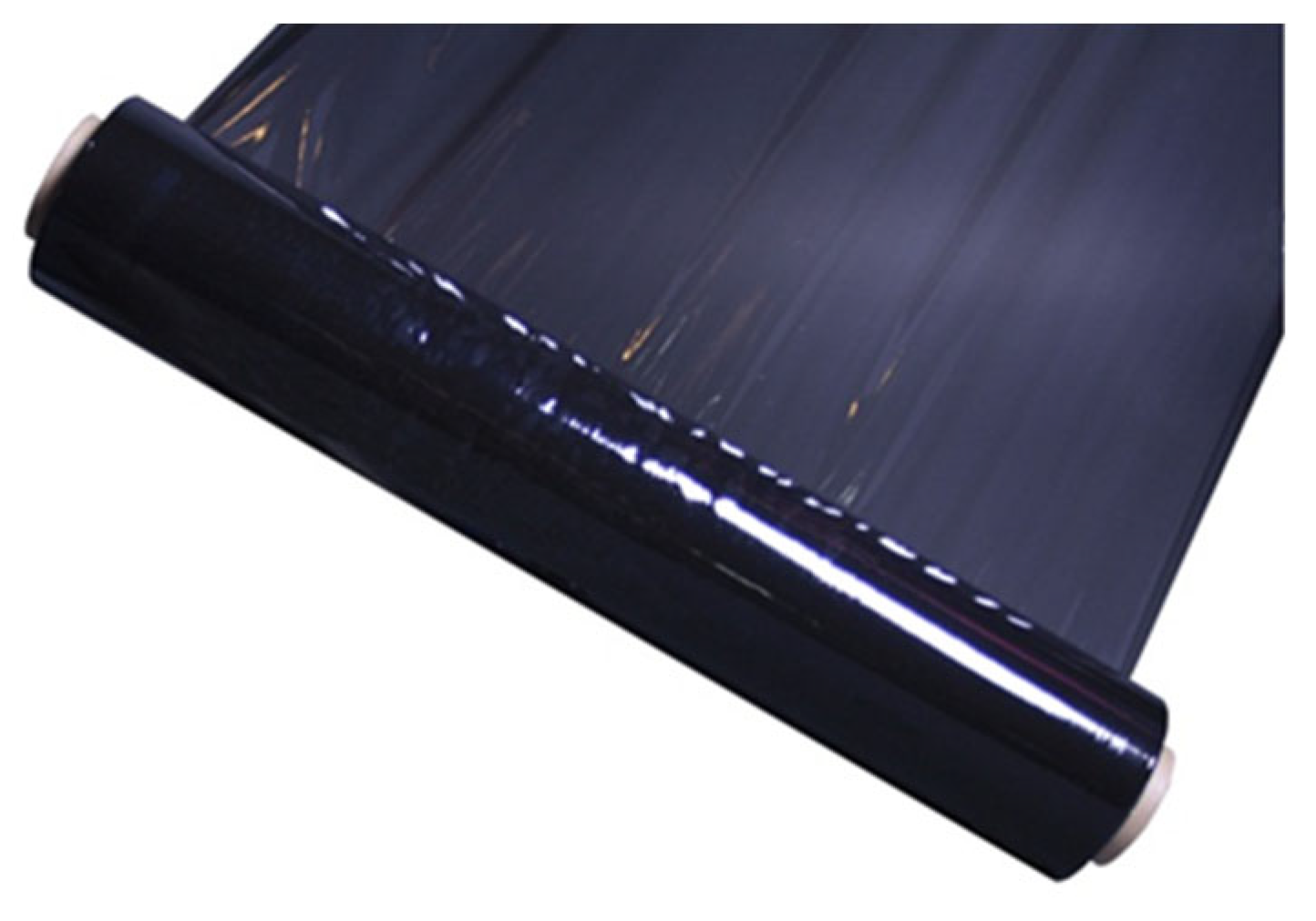
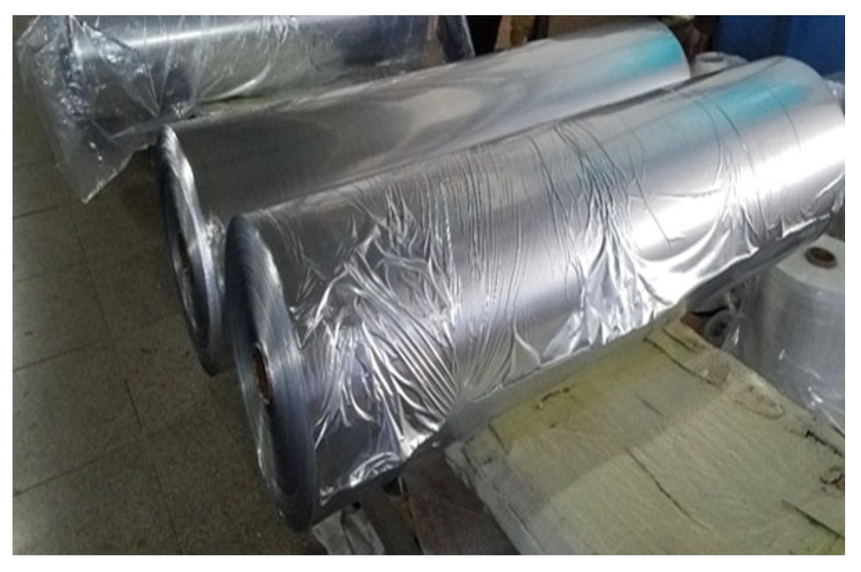
11] in hermetically sealed bags. This achievement is ensured by the total integrity of the sleeve materials, consisting of high-density, three-layer polyethylene. The white outer layer of the sleeve contains titanium dioxide, which reflects the sun’s rays and prevents the temperature inside the sleeve from dropping down [
12].
Two black layers on the inside protect the product from the penetration of sunlight. All three layers are inseparable; each of the layers is made of different polymers with different additives and stabilizers. The sleeve material must provide increased strength, absolute tightness, and elasticity [
13].
It should be emphasized, once again, that maintaining the microclimate in hermetically sealed bags is responsible for the effectiveness of this technology [
14]. Therefore, the basic task of cereal producers is to ensure the general integrity and adequate strength of the materials from which accumulation sleeves are made [
15].
From the analysis, it was found that most of the defects in the polypropylene film of the agricultural sleeves for grain arise during their drawing, that is, during the extrusion process [
16,
17,
18].
A distinctive feature of these defects is that they cannot be eliminated during the production process (irreparable defects) [
18], that is, they have to stop the entire extrusion line and change it [
19].
In the extrusion industry, there is an increasing tendency to combine various control devices under the control of one common device that exercises full control and management of all mechanisms of the extrusion line. It should be noted that a plurality of extruder control stages can be implemented in a hierarchical relationship. The most common devices combine temperature control in different areas [
20]. Most often, the task of such systems is to maintain the specified melt parameters by controlling the heating of the first two or three zones, which are closest to the zone where the polymer melts. The change in temperature in such zones is carried out automatically by the cascade control system. However, in this way, it is possible to carry out an adjustment at a rather low velocity, since the response of the zones of the working volume to changes in temperature parameters is very slow. Pressure control systems are also often found to rely on a smooth change in screw velocity, in order to maintain a constant pressure of the polymer melt [
21].
New types of extruders are often equipped with a microprocessor system that allows simultaneous control and management of the temperature and pressure of the melt, as well as the thickness and width of the extrudate and other extrusion parameters [
22]. Some control systems can be combined into general production management. For example, they allow, in addition to controlling the extruder, for the control of the systems that prepare the material for loading into the extruder, the parallel extruder during coextrusion, the drive and temperature of the gear pump, the system to control the strength and cutting the edges of the extrudate, and many other parameters [
23].
When analyzing the literature, it becomes clear that truly complete control of the extrusion process is not achieved in practice [
24,
25].
In order for systems to be called a system of truly total control, it must exercise control in the following way: the controlled process must be considered a system of many variables, the relationship of which is fully known and taken into account in the control system. However, most microprocessor control systems that control the parameters of the extrudate polymer melt are more similar to a set of uncoupled feedbacks, each of which controls only one parameter. Thus, such a device is a simple combination of several regulators in one package, without changing their essence. Such regulators may provide a lower cost, but do not improve the adequacy of the controlled circuit.
There are two fundamentally different methods for controlling actuators: the pulse and smooth adjustment methods.
The work cycle in the pulse method is as follows. If the extruder temperature is below the set level, the heaters operate at full capacity; as soon as the temperature exceeds the threshold, the heaters are turned off completely.
However, with this type of control, a serious problem arises, in the form of a thermal delay, which is the time difference between the moment the signal is sent to the heater to turn on and heat flow reaches the thermometer (a similar situation occurs when the heaters are turned off).
As a result of this method of regulation, the temperature will fluctuate around the desired value, and the amplitude and frequency of the oscillations will be determined by the delay time of a particular apparatus. In addition, there is a problem with electrical noise and uneven temperature in the extrudate, which can cause high-frequency switching in the circuit when the temperature is close to the set temperature.
The disadvantages of the feedback of the type described above stem from its stepping, that is, due to the fact that two modes of operation of the heater are possible: fully on or completely off. At the same time, in most cases, to maintain the set temperature, the heaters must not operate at full capacity. Thus, the use of pulse control will inevitably lead to the occurrence of temperature pulsations. Therefore, a circuit is needed that automatically smoothly adjusts the power supplied to the heater; then, it will be possible to eliminate pulsations.
To build a truly complete control system, it is necessary to build a dynamic model of the process. In this case, the adequacy of control will directly depend on the accuracy of the constructed model. However, building such a model, in practice, is a very difficult task. Therefore, in this work, attention was paid to the most important parameter of the extrusion process, which affects the quality of the resulting melt and sleeve as a whole. Controlling the temperature of the barrel and forming tool (die) of the extruder is necessary to ensure the consistency of the viscosity of the polymer. Deviations in the viscosity of the material can lead to deterioration of its properties, the occurrence of unacceptable loads on the screw and extruder drive.
Thus, it is necessary to fully analyze the operation of the extrusion line, identify the “weak points” of production, and provide recommendations and specific technical solutions for troubleshooting, as well as for obtaining sleeves with higher-quality indicators.
The novelty of the research lies in the development of an automated system that is able to control the temperature regime in the production of polyethylene film by installing a temperature sensor with feedback, which ensures the quality of the film.
2. Materials and Methods
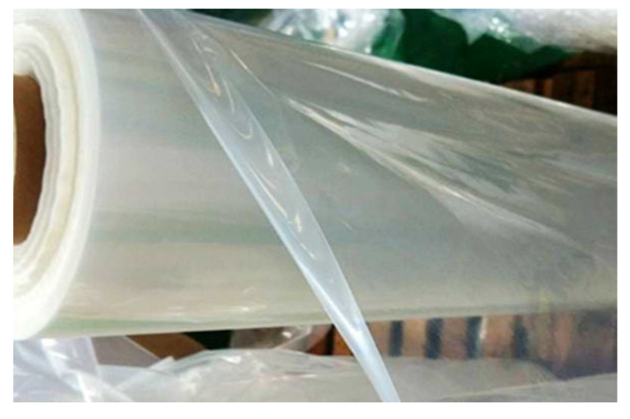
2.1. The Polypropylene Film Defects
In order to analyze the quality of the polypropylene film, the most common defects that occur during its manufacture at the production site under the conditions of Altyn Arna Holding LLP in Karaganda were identified, which were conditionally divided into 3 groups. The most common defects are shown in
Figure 1,
Figure 2,
Figure 3,
Figure 4,
Figure 5 and
Figure 6. The defects were determined visually and using a magnifying glass.
Longitudinal stripes, scratches (due to defects on the working surface of the forming tool), and contamination from film burns form. Foreign inclusions occur due to sleeve jerk and dirty raw materials. Gel bubbles may appear as a result of poor homogenization of the melt and rupture of the filter meshes. Contaminated or damp raw materials can cause a ‘fisheye’ defect.
The average thickness of the half-length sleeve is greater (or less) than the specified value, which is a consequence of the noncorrespondence of the melt extrusion, product removal rates, and inaccurate calibration of the forming gap. The leakage of the air supply system in the sleeve affects the instability of the inflation of the sleeve and uneven width or thickness of the polymer sleeve. The asymmetry of the swollen sleeve may appear, due to the adhesion of oxidized materials or impurities to the walls of the forming channels. A low mechanical strength is found, as a result of the inhomogeneous mixing of the melt and unregulated temperature conditions.
Manufacturing defects have been established to arise, as a result of the operation of the equipment and affect the quality of the film.
Film manufacturing defects include:
- −
The accumulation on the surface of the film;
- −
Unstable yield after extruder starts;
- −
Decreased line performance due to insufficient sleeve cooling;
- −
Wabble.
Film manufacturing defects occur due to temperature mismatch, instability of the extruder barrel or head, clogging of the screens, and uneven roll velocity.
Variation in the thickness of the polymer sleeve is the most painful point in the industry, as it affects the maintenance of a certain humidity and temperature, while storing grain in polyethylene sleeves.
2.2. Working Principle of the Extrusion Line to Produce a Polypropylene Film
The operation of the extrusion line (Labtech Engineering Company Ltd (Thailand), LF-600/LCP models) for the production of polyethylene sleeves, installed under the conditions of “Holding AltynArna” LLP (Karaganda City, Kazakhstan) is considered.
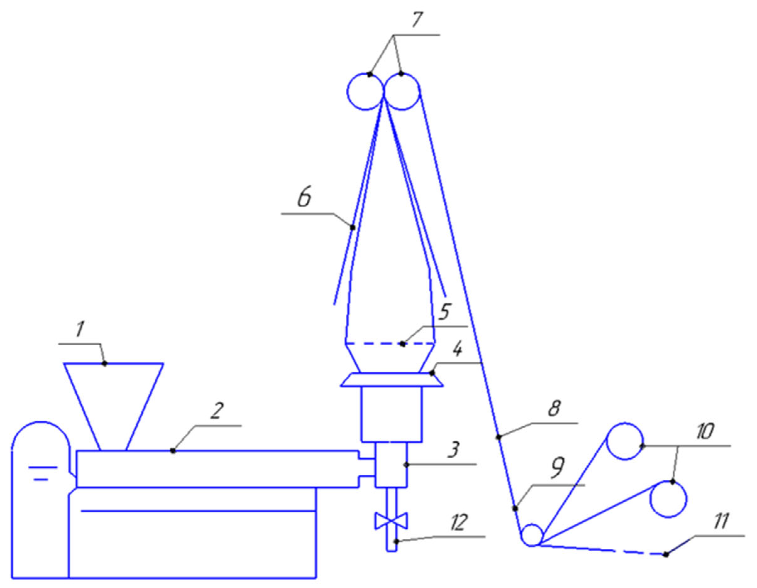
Figure 7 shows the technological diagram of the extrusion line.
The principle of operation is as follows. The dried granules are fed by pneumatic transport into hopper 7 of the extruder. Under the action of gravity, the granules move downward and fill the interturn space of the screw in zone I. The rotating screw moves the polymer along the barrel into extruder 2, which forms the annular angle head 3. The rotating screw moves the polymer along with the barrel in zones II-III and into the annular head. In the head, the melt is cut by a mandrel and, upon leaving, has the shape of a barrel. To give it dimensional stability, the extrudate is cooled from the outside by air coming from the slot of the hollow ring 4. The moment of solidification of the melt (for crystallizing polymer is crystallization) is fixed by the appearance of a characteristic cloud point of the sleeve, the so-called crystallization line 5. Up to this line, the extruded sleeve is stretched along its length by the pulling rolls 7 and blown out by the air inside the sleeve along the diameter. To start inflating the sleeve, there is a special air channel 12 in the head mandrel, which is connected to the blower. Air is fed into the sleeve periodically as it diffuses through the film and leaks through leaks in the film layers between the pinch rolls. Stretched in two or in one direction, the film after the crystallization line continues to be cooled by ambient air, and then gradually folds folding cheeks, diverging at a certain angle 6. The movement of the film and its drawing is carried out by a rubberized pair of rolls tightly pressed to film 7. Then, the sleeve is in folded view and can either be cut on the sides with knives 9 and wound into two bobbins 10 in a single layer or not cut and wound in a double layer on one bobbin. The two cut edges 11 are processed in a granulator and prepared to the primary polymer material.
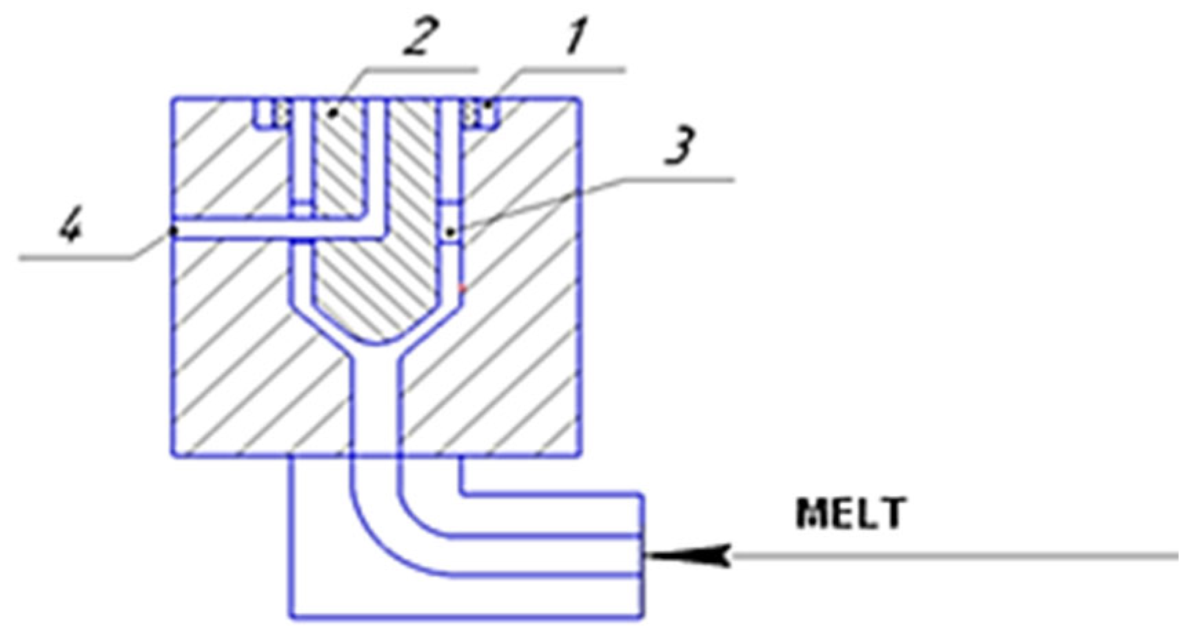
Figure 8 shows that the most critical technological unit in the extrusion unit is the angular angle head. In the production of sleeves films at AltynArna Holding LLP, extrusion plants are used to eliminate the pulsation of the melt, with the ratio L/D = 20–25, with D from 20 to 90 mm. The films are obtained after stretching and blowing, with a thickness of 10 to 300 µm and thickness variation of ± 10%.
The temperature of the forming tool usually only affects the surface quality of the film, as the material is in the forming die for a relatively short period of time.
It is observed that a noticeable change in extruder performance is observed only when the change in heating power occurs in the loading zone. With changes in heating power in areas close to the end of the screw, the productivity changes within the accuracy of the measurement, i.e., controlling the temperature of the polymer melt in areas near the end of the extruder screw has no effect on the performance [
26].
Furthermore, it is noted that, in the stationary mode of operation of the extruder, a linear dependence of the change in the temperature of the polymer melt ΔTp on the change in the heating power ΔPi, supplied to the i-zone of the extruder barrel, is observed. When the effect of the input power on heating is stronger, closer to the end of the screw is the considered zone of the extruder barrel [
21].
Temperature control of the polymer melt in extruder presses is carried out by stabilizing the temperature in the heating zones of the extruder with temperature control of the last zone of the extruder barrel [
27,
28].
To build a system for automatic control of the temperature of the polymer melt at the outlet of the dosing zone of the extruder, it is necessary, in one way or another, to find an adequate dynamic model of the control object. In the overwhelming majority of cases, the method of experimentally obtaining the transient characteristics of the control object with their subsequent identification is used. In particular, the object of regulation, the output of which is the temperature of the polymer melt and input is the power of the heating elements, is described as a first-order aperiodic link. The parameters of the first-order aperiodic link are the transmission coefficient and time constant. They are determined by the transient response taken experimentally.
The control object is considered and described as a control object with lumped parameters. The existing dependence of the controlled variable, temperature of the polymer melt, and spatial coordinates (primarily on the longitudinal coordinate of the screw) is ignored.
The dynamic behavior of the extruder is largely determined by its temperature control system. Therefore, it is important to understand the basic characteristics of various temperature control systems. Most of these systems have feedback; that is, the measured values are sent to the control unit, which, on that basis, issues signals to the actuators.
2.3. Deformation Process
In the manufacture of polypropylene sleeves, the main technological operations are to blow, draw, and cooling of the sleeve blank [
16]. The influence of technological parameters on the quality of the process is necessary. The tubular extrusion rod, leaving under low pressure, at a certain velocity, Vex, is subjected to air cooling through channel 4 (
Figure 8), and it is stretched along the length by pulling rolls, inflated across the width by air supplied to the inside of the sleeve. Therefore, the sleeve must have the maximum deformation capacity, which is achieved by using a melt with a lower melt flow rate.
The deformation process occurs between the die and solidification line, and the cooling continues until the film is compressed by the pulling rollers [
29]. Thus, up to the crystallization line, there is:
Swelling (increase in thickness) of the extrudate relative to the size of the annular gap of the die;
Stretching and/or blowing of the tubular blank;
Cooling of the melt;
Crystallization (to crystallize polymers).
Elastic swelling of the extrudate occurs as a result of the highly elastic deformation accumulated in the polymer melt. The highly elastic deformation of the melt is formed when it passes through the head-forming channels, and its value is greater the higher the shear stress [
30].
Stretching and inflation of the sleeves lead to a thinning of the workpiece and orientation of the chains in the film (hardening) [
31]. Stretch can be quantified by the stretch ratio e
v:
where
—film velocity after the pulling rolls equal to the linear velocity of rotation of the pulling rolls.
—extrude exit velocity.
Accordingly, the degree of inflation e
inf is determined as follows:
where
Dsl—swollen sleeve diameter.
dg—is the diameter of the sleeve emerging from the head annular gap.
Film thickness
dfil can be calculated by the formula:
where
—extrudate thickness (neglecting melt swelling, we can assume
=
(
is a head annular gap thickness)).
The total amount of deformation of the extrusion tubular billet is estimated as:
Having previously calculated the productivity of the extruder
Q = 0.68
D2,5 (
D—is the diameter of the screw) [
31], you can calculate the velocity V
ex:
where
—cross-sectional area of tubular billet—melt.
is melt density.
In practice, we often have values of einf from 2.5 to 3.5 and ev from 1.5 to 3.0.
Large values of einf and ev lead to a decrease in the stability of the sleeve dimensions, a noticeable manifestation of the defects in the design of the equipment and uniformity of cooling. With an increase in einf and ev, the orientation of macromolecules increases, which leads to an increase in the mechanical characteristics of the product. By changing the ratio einf/ev, it is possible to obtain films with an oriented, equal strength or given strength in the longitudinal and transverse directions.
2.4. Cooling Process
Particular attention should be paid to the cooling operation. Sleeve cooling is a common process for transferring heat from a hot surface to the environment [
32]. To calculate the cooling time, usual formulas are used, which can be used to determine the height of the crystallization line and level of location of the pull rolls. The latter is especially important, since a film, for example, made of low-density polyethylene cannot have a temperature higher than 50–60 °C by the time it enters the nip between the pinch rolls. Taking into account the compression force of the sleeve at higher temperatures, the sleeve will stick together. Most of the stretching in the longitudinal direction is performed closer to the forming part of the head, and the blowing is performed closer to the crystallization line. By changing the drawing velocity, the temperature and intensity of the cooling of the sleeve, shape of the sleeve and, consequently, properties of the film, it is possible to obtain the sleeve of the following shapes (
Figure 9).
The shape shown in
Figure 9a corresponds to the high location of the crystallization line H, leading to inadequate cooling of the deformable sleeve. The film is first stretched in length and then in width. This is accompanied by a partial reorientation of macromolecules.
The shape shown in
Figure 9b corresponds to the normal value of H at a good cooling rate. Longitudinal and transverse, draw, and blow orientations occur almost simultaneously. The film has the same strength and thickness.
The shape in
Figure 9c corresponds to intense sharp cooling of the sleeve, and line H is small. The film has a predominantly transverse orientation; for some types of polymers, a decrease in the degree of crystallinity occurs.
The shape shown in
Figure 9d corresponds to the uneven blowing of the film with cooling air around the perimeter. The film has different thicknesses, and the sleeve is asymmetric.
For most films, depending on their thickness, the value of the crystallization line height ranges from 0.3 to 2 m. The thicker the film (and, accordingly, the extrusion billet), the greater the crystallization line height, and vice versa.
Therefore, the main requirement for extrusion dies, as a responsible technological link of the entire line, is the constant resistance to melting in the channels of the forming tool and, consequently, the constant extrudate throughout the perimeter of the forming hole [
33]. The accuracy of adjusting the gap of the forming part of the head further determines the size of the difference in the thickness of the films.
The design of the head should provide full alignment of the melt flow along the perimeter of the slot. The slot gap is adjusted using micro screws.
Cooling and crystallization of the polymer sleeve are necessary to control the rate of orientation and crystallization up to the crystallization line [
34], as well as above it, to cool the solid film to temperatures at which the web will not be damaged and stick together, passing between the fold cheeks and further into the gap between the pull rolls. The cooling time of the film limits the velocity of its selection, i.e., the productivity of the extruder. Additional fans, blowers, cooled air, etc., can be used to increase the intensity of cooling with the same dimensions of the installation [
35] and building.
3. Results
3.1. Proportional Temperature Control Device
The proportional control device allows for the smooth adjustment of the power supplied to the heater (from 0 to 100%). The temperature range at which the power changes from 0 to 100% is called the proportional area, and it is expressed as a percentage of the operating range of the device. Usually, the desired temperature value lies in the middle of the proportionality region, although, sometimes, on its upper border. For example, if the device has an operating range of 500 °C, then a proportional band would represent a 25 °C gap.
Figure 10 shows the transfer function of a proportional feedback controller.
This type of controller is called a closed-loop controller because the control signal it produces decreases with increasing temperature. In this case, if the temperature exceeds the upper limit value T2, then the heaters are completely switched off. Otherwise, the heaters turn on at full power. The proportional band width can be adjusted, according to the desired extruder operation. At the same time, a decrease in its width leads to a steeper form of the dependence of the heater power on the temperature. In the opposite case (when the width is set to zero), the proportional controller starts to work as a simple switching controller, and all the benefits of proportionality are lost.
The block diagram of the proportional controller is shown in
Figure 11.
The output signal (supplied to the heater) is described by the equation:
when the desired temperature value is set in the middle of the proportional region, the power supplied to the heaters at a zero value, if signal
e is equal to 50%.
In real conditions, such a situation rarely occurs when, in order to maintain the set temperature, it is necessary to turn on the heater at exactly half the power. Therefore, the temperature will start to rise or fall, adjusting the power level supplied to the heater, until an equilibrium is established that maintains some discrepancy between the set and actual temperature, called the operating deviation. The operating deviation can be reduced by narrowing the proportional band; however, if the proportional band is too narrow, instability may occur.
Figure 12 shows a graph of the extruder’s output to the temperature regime, when using a proportional temperature controller.
3.2. The Advantages and Disadvantages of the Extrusion Line
The film for the sleeves produced under the conditions of AltynArna Holding LLP.
This line operates on the principle of film production with the sleeve upward. After analyzing the operation of a particular extrusion line, several advantages and disadvantages of both technological and structural nature were identified:
Upward retraction of the sleeve saves production space;
The sleeve is evenly cooled throughout the perimeter and height;
The thickness of the resulting film can be increased several times (if necessary), since the sleeve is accepted (held) by the pulling rollers, without breaking or breaking;
Turning the melt flow by 90° in the head slightly increases the cost of manufacturing the tooling.
3.3. The Main Technological Parameters Affecting the Quality of the Polypropylene Film
The main technological parameters that have a significant effect on the quality of the polypropylene film (appearance) are the quality of raw materials (values of the melt flow rate, molecular weight distribution), extrusion temperature (at the head) (Te), screw rotation, frequency (N), etc.
On the basis of the experiments carried out, we can say that varying parameters, such as the height of the crystallization line (H), degree of elongation ev, and degree of inflation (einf) have a direct effect on the physical and mechanical properties of the finished sleeve.
Figure 13,
Figure 14,
Figure 15,
Figure 16 and
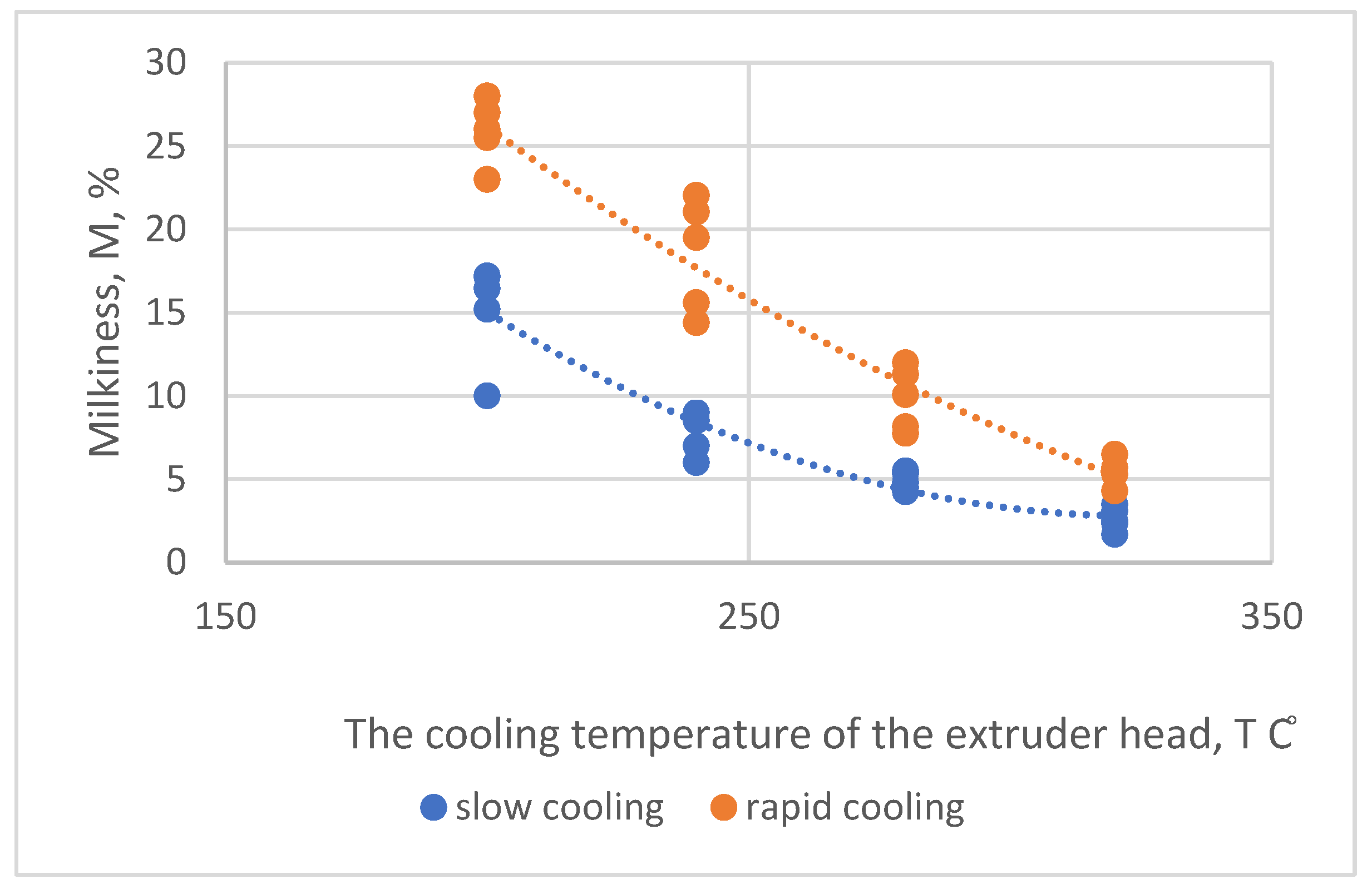
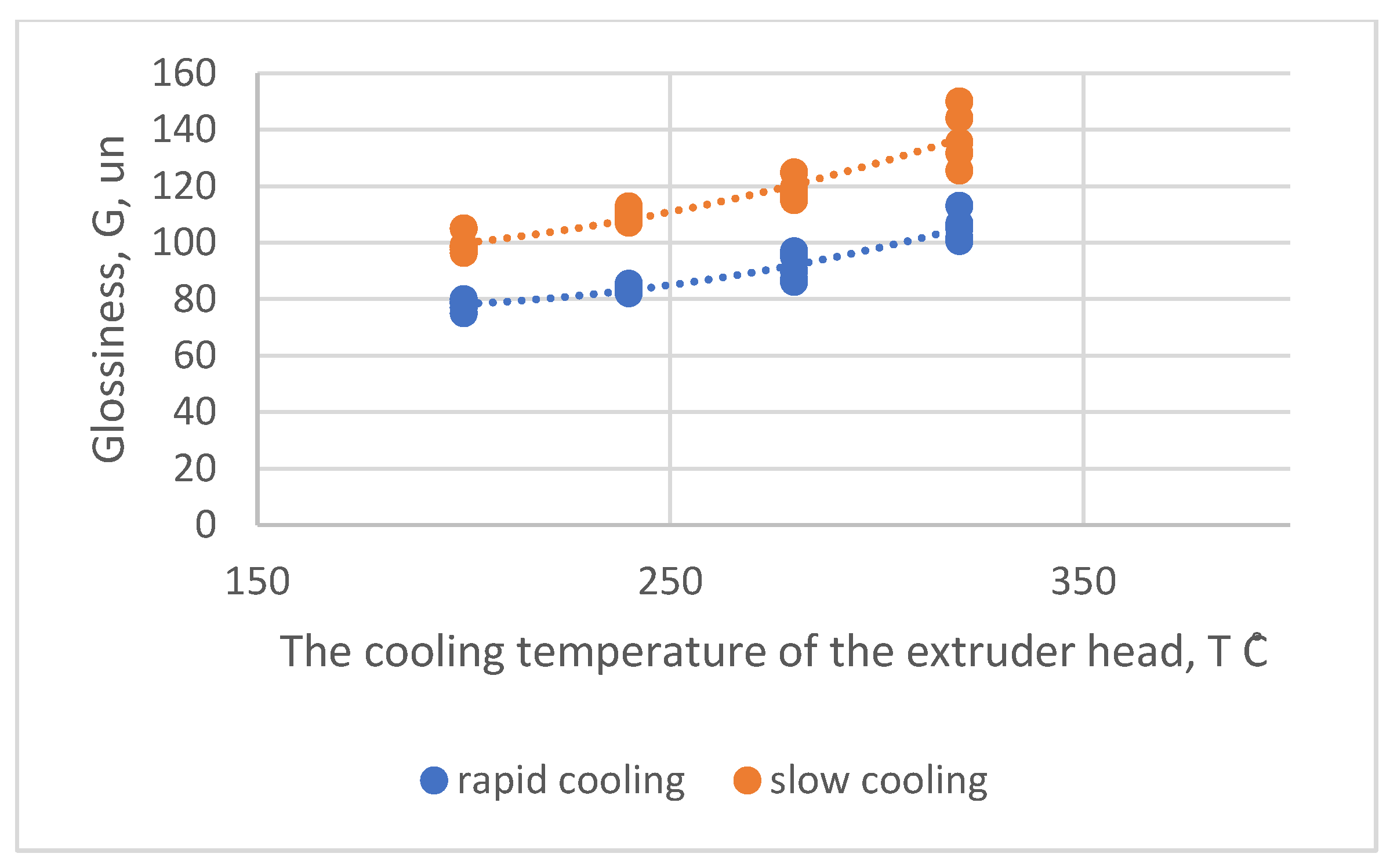
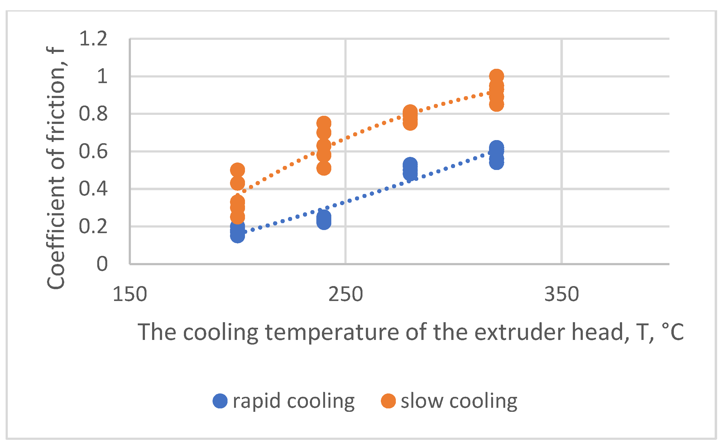
Figure 17 show the influence of the parameters T
e and N on some characteristics of the film, provided that other technological parameters of the process are constant. An increase in gloss and decrease in the coefficient of friction of films with increasing T
e allow us to say that, in this case, the elastic turbulence of the melt decreases, and the relaxation processes take place more fully.
With an increase in Te, macro defects (longitudinal stripes, local thickenings, defects of the “fish eye”, “gel” type, etc.) decrease, and the supramolecular structure, as determined by the temperature and time of crystallization, changes. With increasing Te, as well as an increase in the melt flow rate, the optical properties of the films are improved. Therefore, to obtain both smooth and shiny films, increasing the value of the Te parameter or decreasing the value of the N parameter is recommended. For these purposes, it is better to use a polymer with the minimum permissible molecular weight.
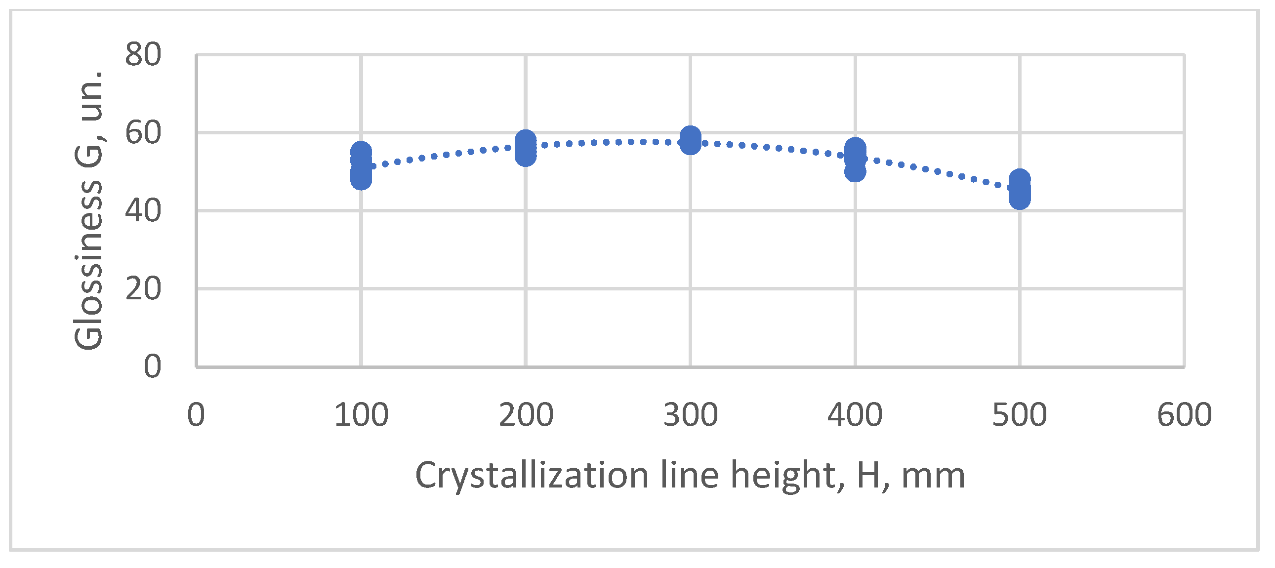
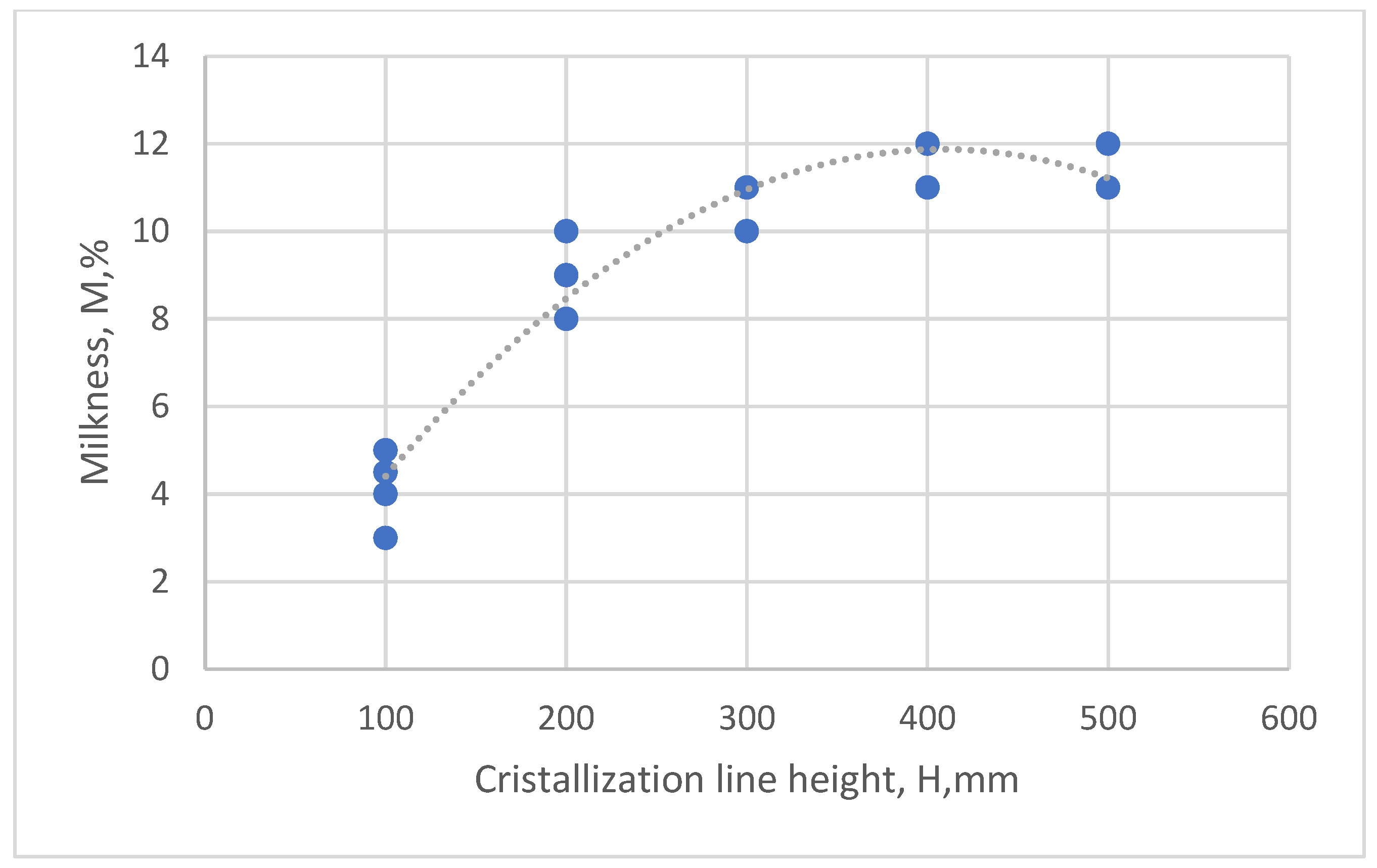
A change in film cooling modes significantly affects its optical properties and is reflected in such a complex characteristic as the height of the crystallization line H in
Figure 12. The higher the H, the longer the time the melt cools. When the fact that there is a uniaxial or biaxial drawing of the film at the same time is taken into account, the structure of the product undergoes significant changes.
Therefore, with an increase in the parameter H in
Figure 13, due to a decrease in the blowing intensity of the workpiece, or an increase in the screw rotation frequency N or extrusion temperature T
e, the turbidity of the film increases. This is because as the crystallization time of the polymer increases, and the formation of larger supramolecular formations occurs, i.e., the structural inhomogeneities of the films increase. The film gloss is also reduced if the H parameter is in the range of 200 to 300 mm or more.
If the parameters e
inf and e
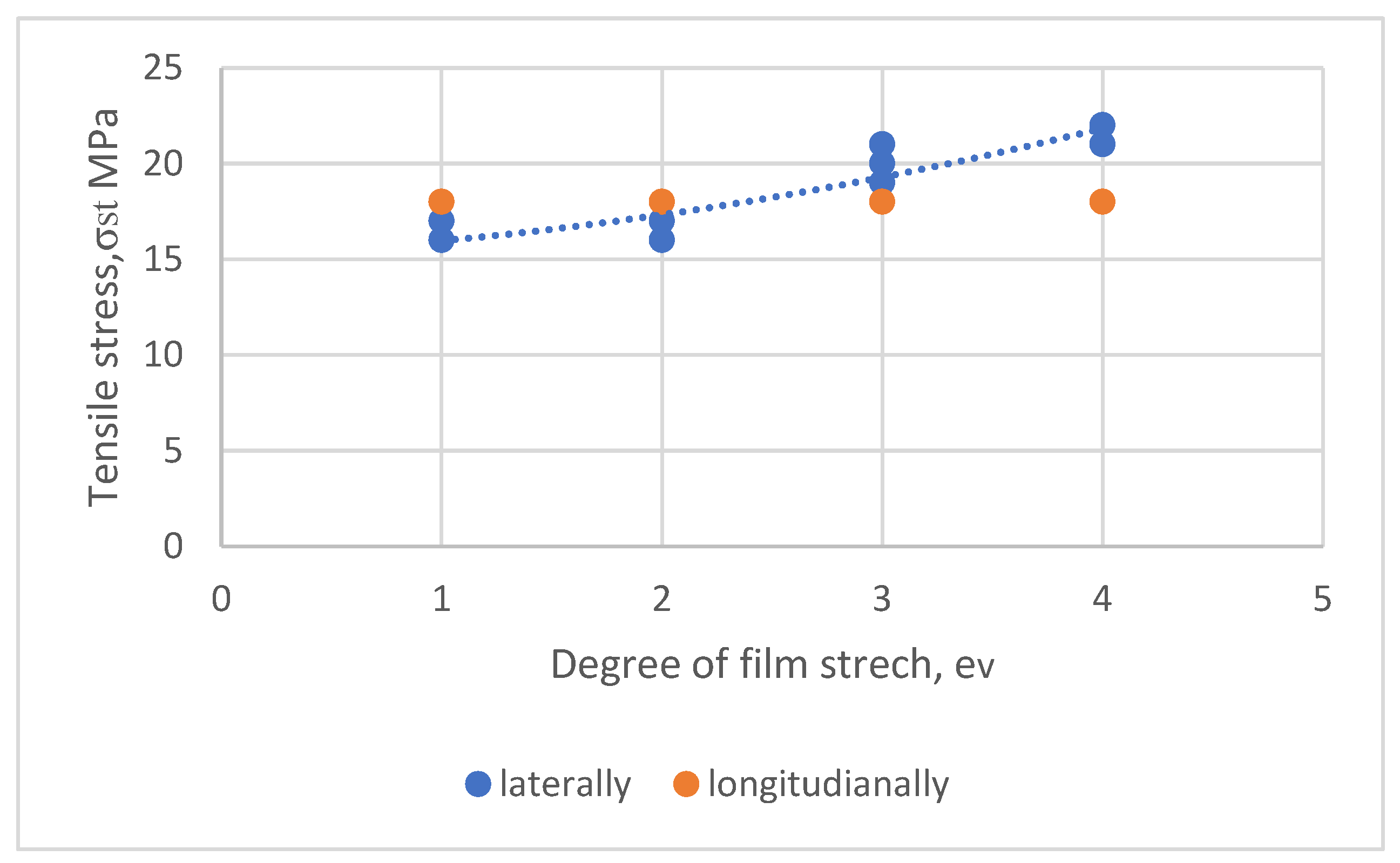
v are constant and parameter H increases, the strength practically does not change; however, the elastic modulus increases slightly, indicating a slight increase in the degree of crystallinity. The most significant effect on the strength properties of the films is exerted by the values of the parameters e
p and e
σ (
Figure 18).
For example, with an increase in the degree of elongation ev, due to an increase in macromolecule orientation, the tensile strength σst increases significantly. With a simultaneous increase in the parameters einf and ev, the strength of the films increases in both directions. With an increase in the parameter σst, the tensile elongation of the samples decreases slightly. The increase in the parameter σst upon blowing or stretching in films is relatively small, since, in the molten state, the proportion of highly elastic deformation is small, due to the intense relaxation processes of the oriented macromolecules.
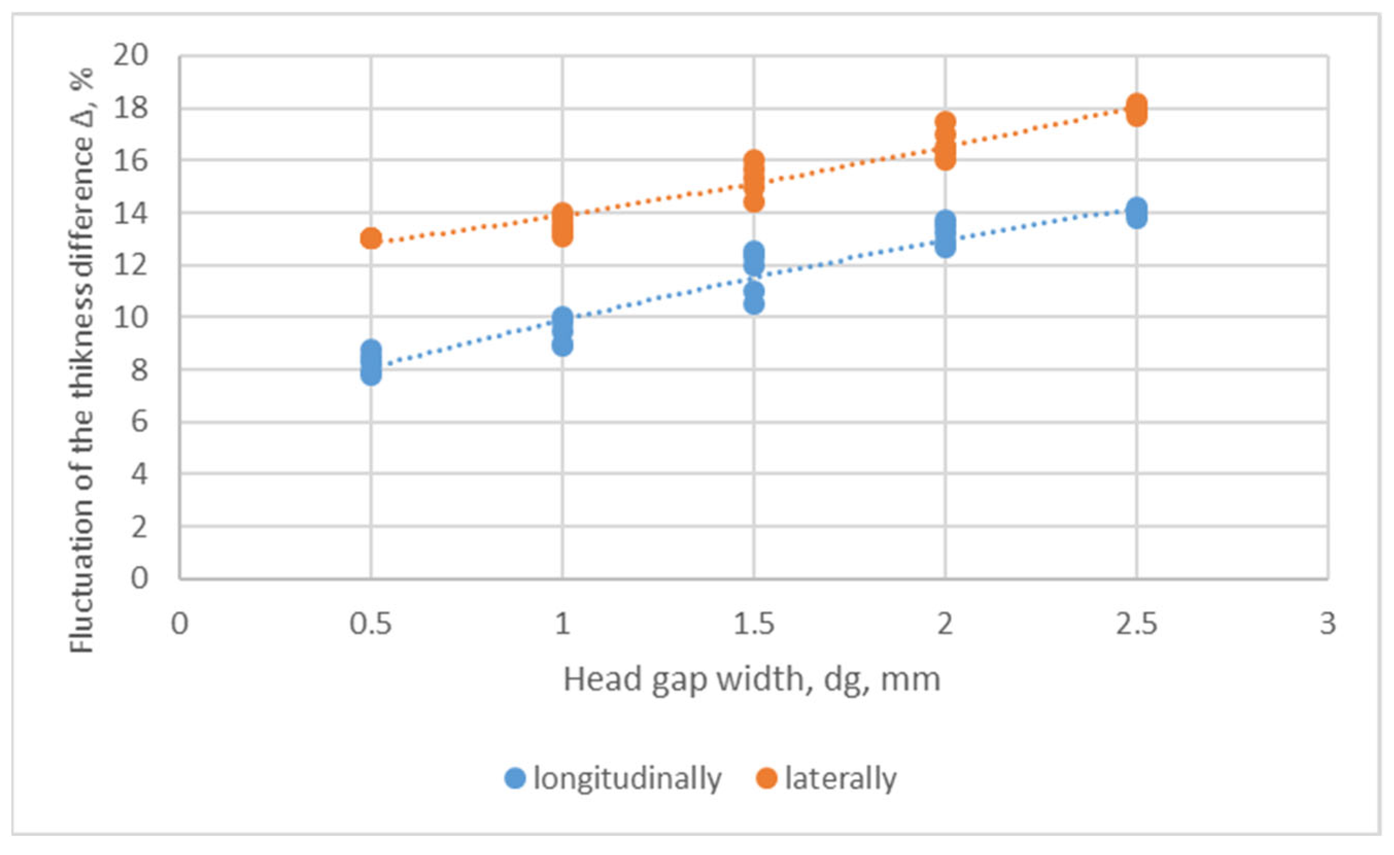
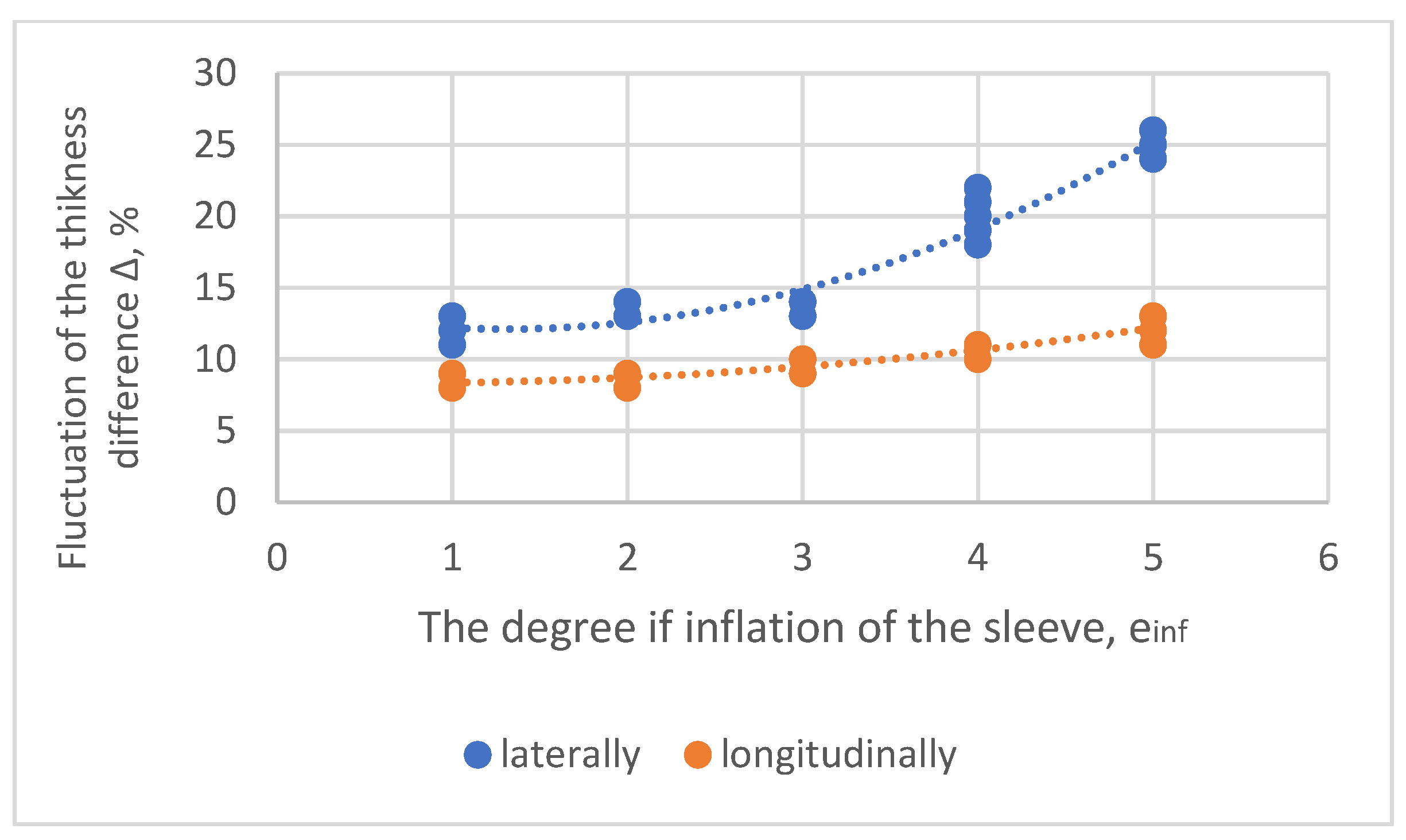
Furthermore, it was found that an essential characteristic of the quality of the film is its thickness variation. There is no universal dependence of the influence of certain technology parameters on the thickness variation because the uniformity of cooling, type of machine, quality of the slotted ring head, accuracy of the gap control, homogeneity of the melt, etc., have a significant effect. However, some general patterns can be distinguished.
Figure 19 and
Figure 20 show how the difference in the thickness D of polyethylene films changes, depending on the width of the hole in the head dg and degree of inflation of the sleeve e
inf. The following conclusions can be drawn from this figure:
As can be seen from the graphs, the orientation of the films has a great influence on the geometric stability at elevated temperatures. The higher the orientation (and strength), the greater the shrinkage of the films. This property can be useful for the specially prepared shrink films used to package various items.


 ,
, 


