Author Contributions
Conceptualization, H.G., M.Ž. and D.Š.; methodology, H.G. and M.Ž.; software, H.G. and M.Ž.; validation, D.Š. and M.Ž.; formal analysis, M.Ž., H.G. and D.Š.; investigation, H.G., M.Ž. and N.V.; resources, D.Š. and N.V.; data curation, H.G. and M.Ž.; writing—original draft preparation, H.G. and M.Ž.; writing—review and editing, M.Ž. and D.Š.; visualization, H.G. and M.Ž.; supervision, D.Š.; funding acquisition, D.Š. All authors have read and agreed to the published version of the manuscript.
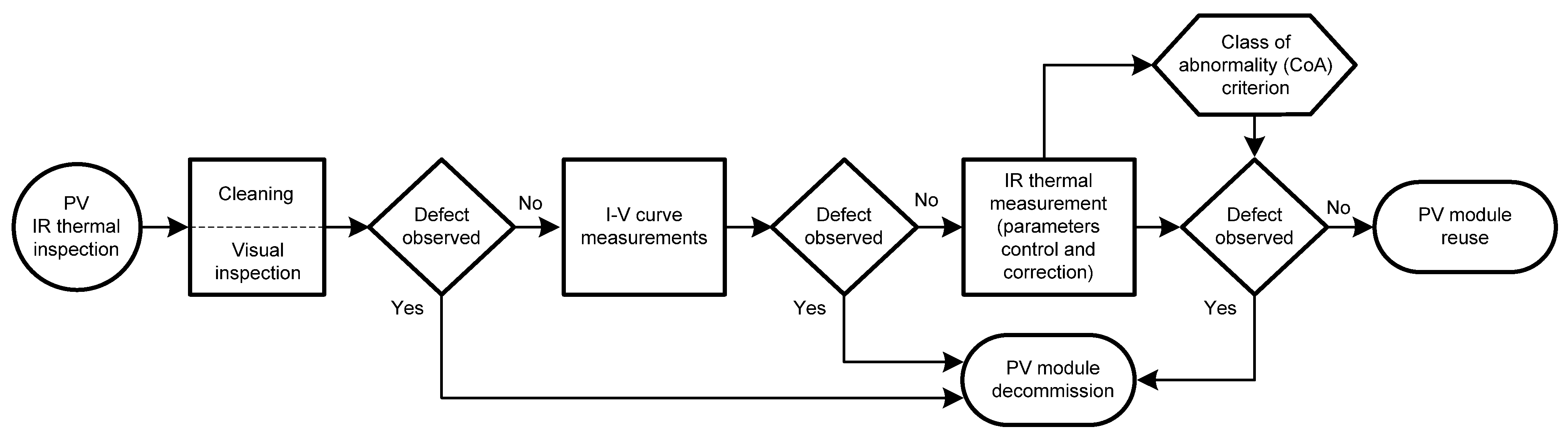
Figure 1.
Flow chart of the test procedures.
Figure 1.
Flow chart of the test procedures.
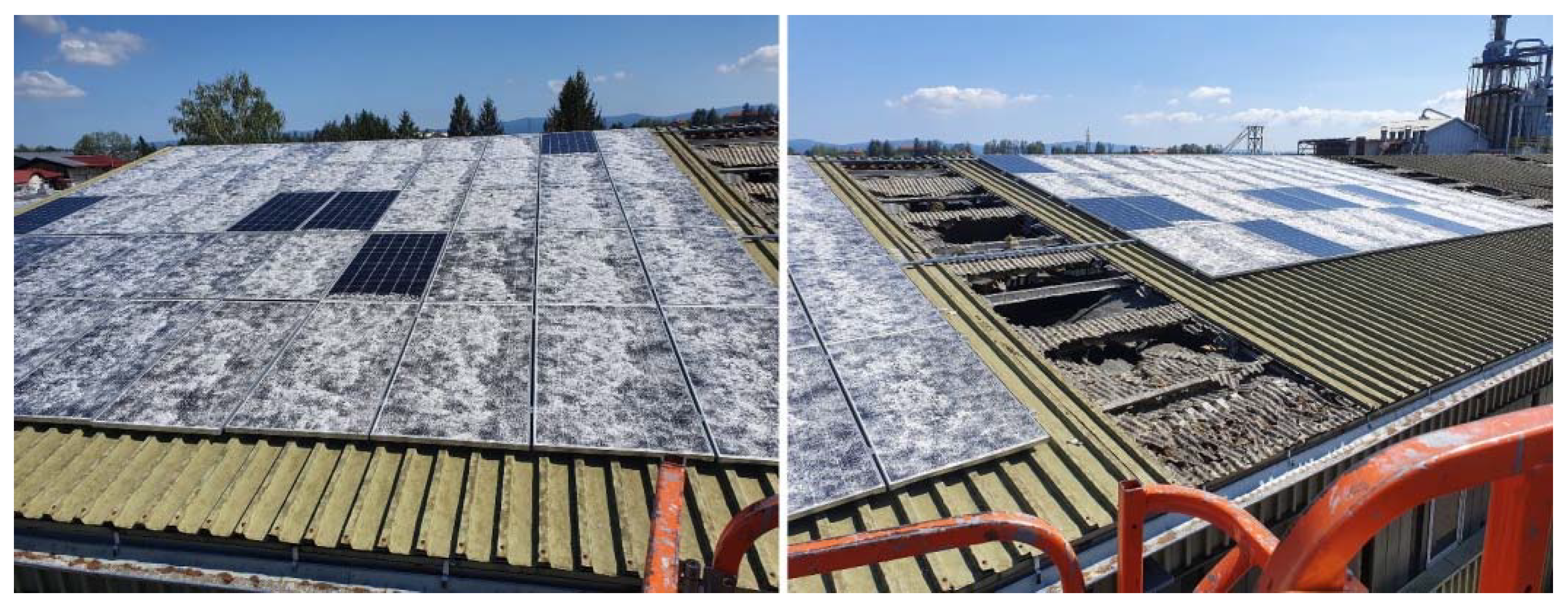
Figure 2.
Photographs of damaged PV arrays of the studied test site.
Figure 2.
Photographs of damaged PV arrays of the studied test site.
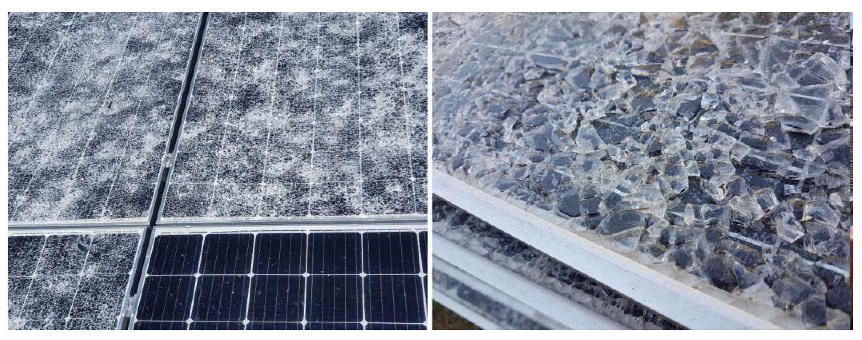
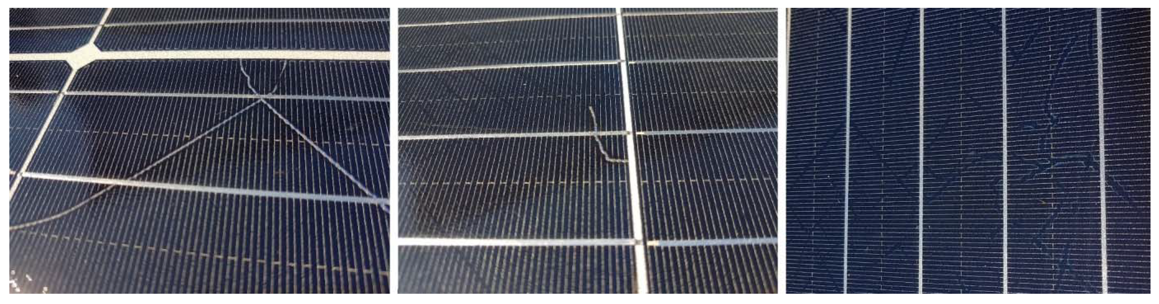
Figure 3.
Close-up on a part of a damaged PV array of the studied test site.
Figure 3.
Close-up on a part of a damaged PV array of the studied test site.
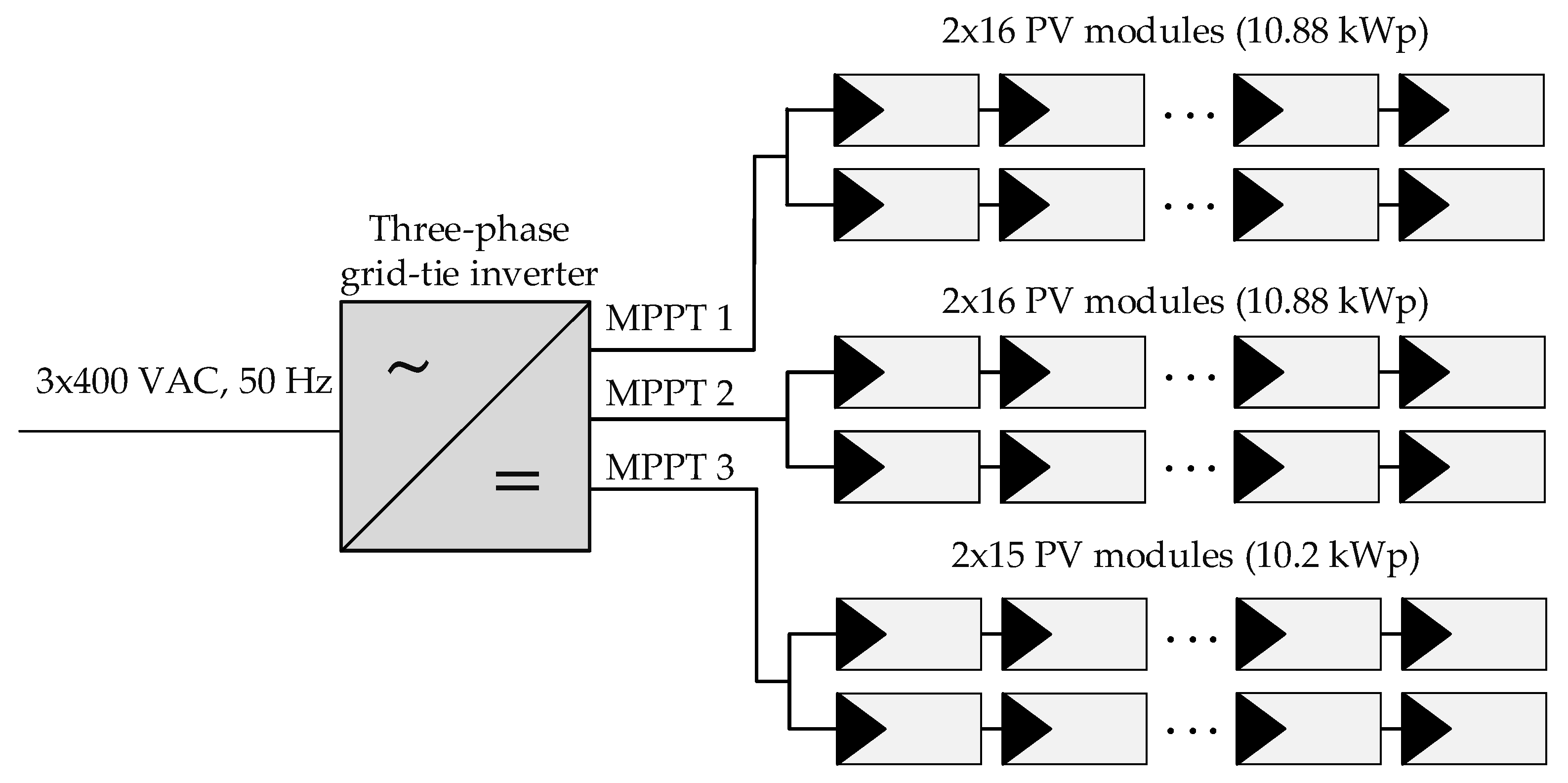
Figure 4.
The 30 kWp PV plant layout.
Figure 4.
The 30 kWp PV plant layout.
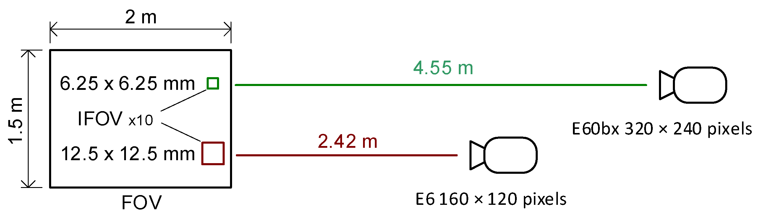
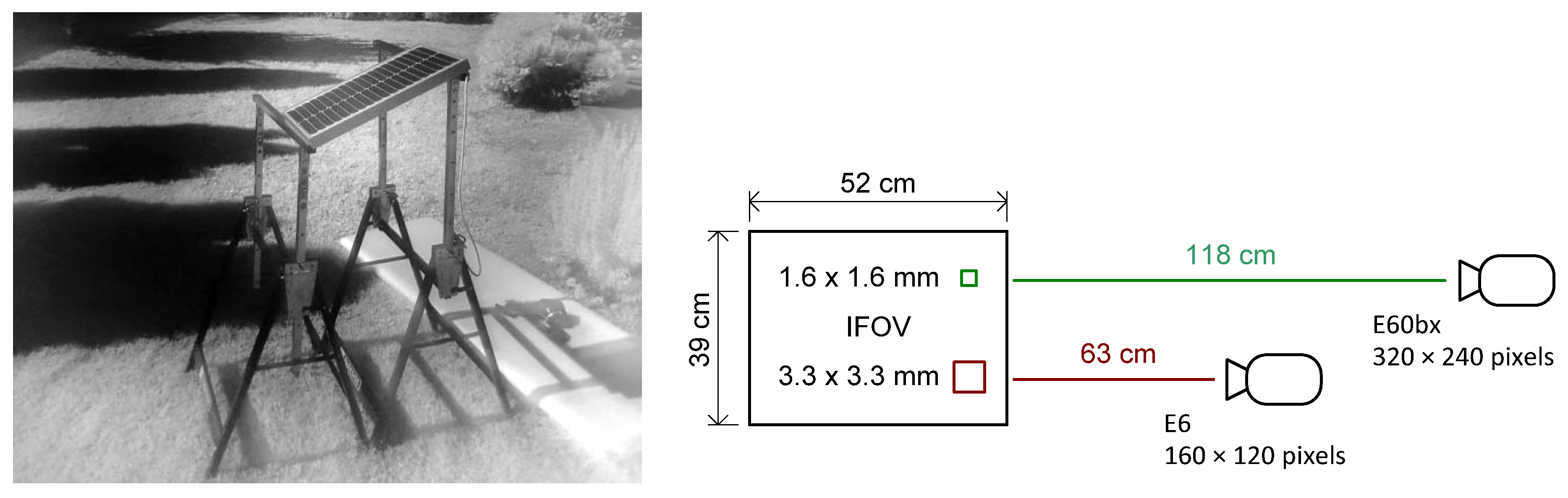
Figure 5.
FOV and IFOV of the available Flir E6 and Flir E60bx cameras.
Figure 5.
FOV and IFOV of the available Flir E6 and Flir E60bx cameras.
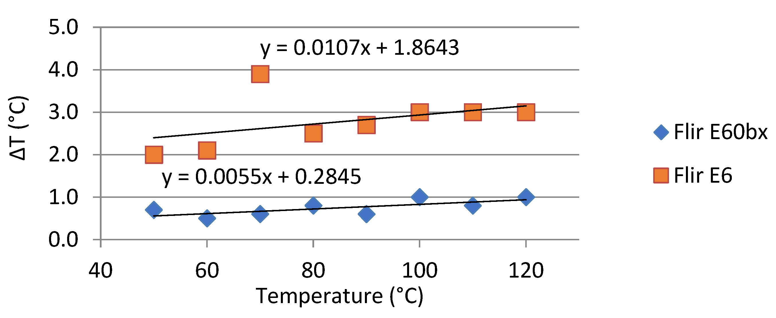
Figure 6.
Calibration results of the Flir E6 and Flir E60bx cameras.
Figure 6.
Calibration results of the Flir E6 and Flir E60bx cameras.
Figure 7.
Photograph of the pilot setup, taken at 720 nm.
Figure 7.
Photograph of the pilot setup, taken at 720 nm.
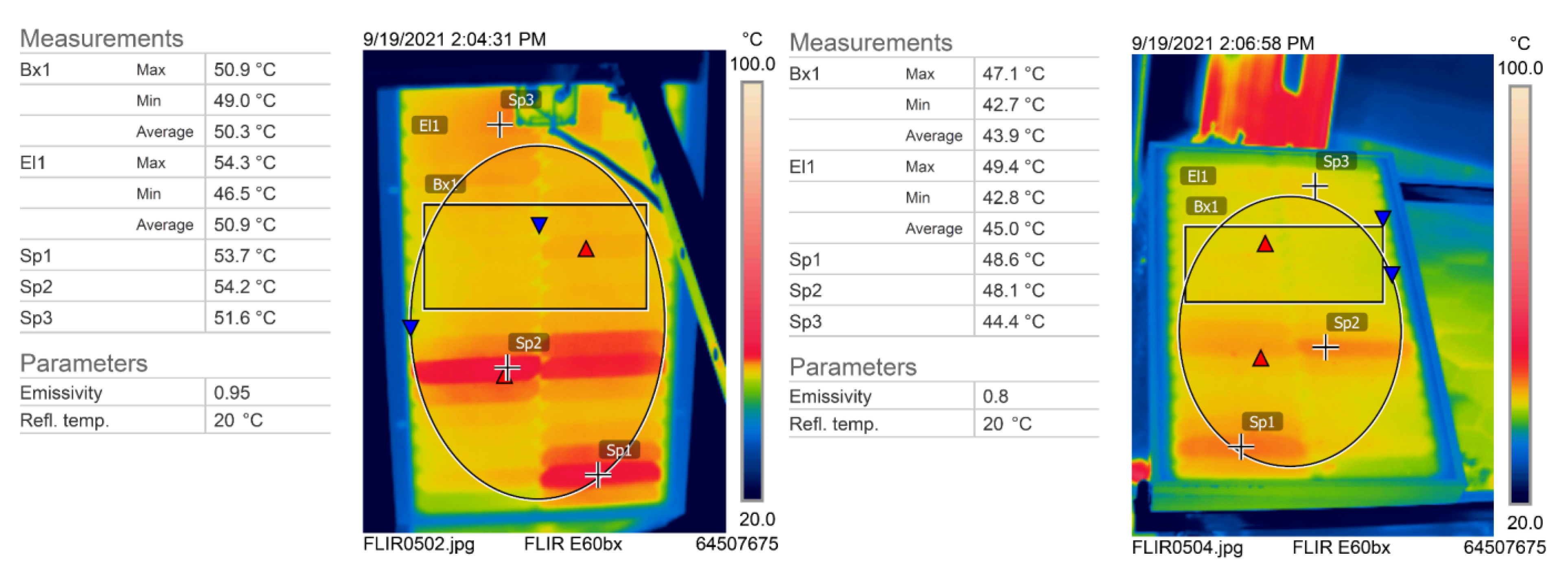
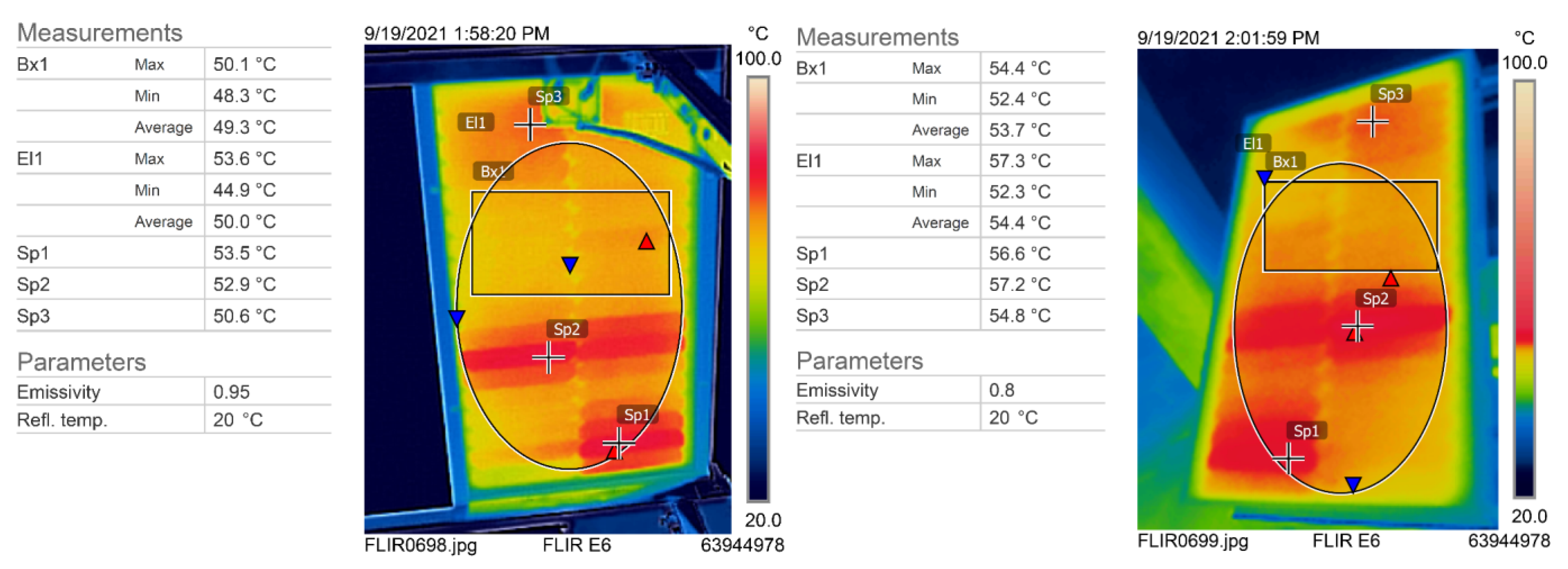
Figure 8.
Pilot module thermogram recorded by the FLIR E60bx camera: bottom side (left), top side (right).
Figure 8.
Pilot module thermogram recorded by the FLIR E60bx camera: bottom side (left), top side (right).
Figure 9.
Pilot module thermogram recorded with the FLIR E6 camera: bottom side (left), top side (right).
Figure 9.
Pilot module thermogram recorded with the FLIR E6 camera: bottom side (left), top side (right).
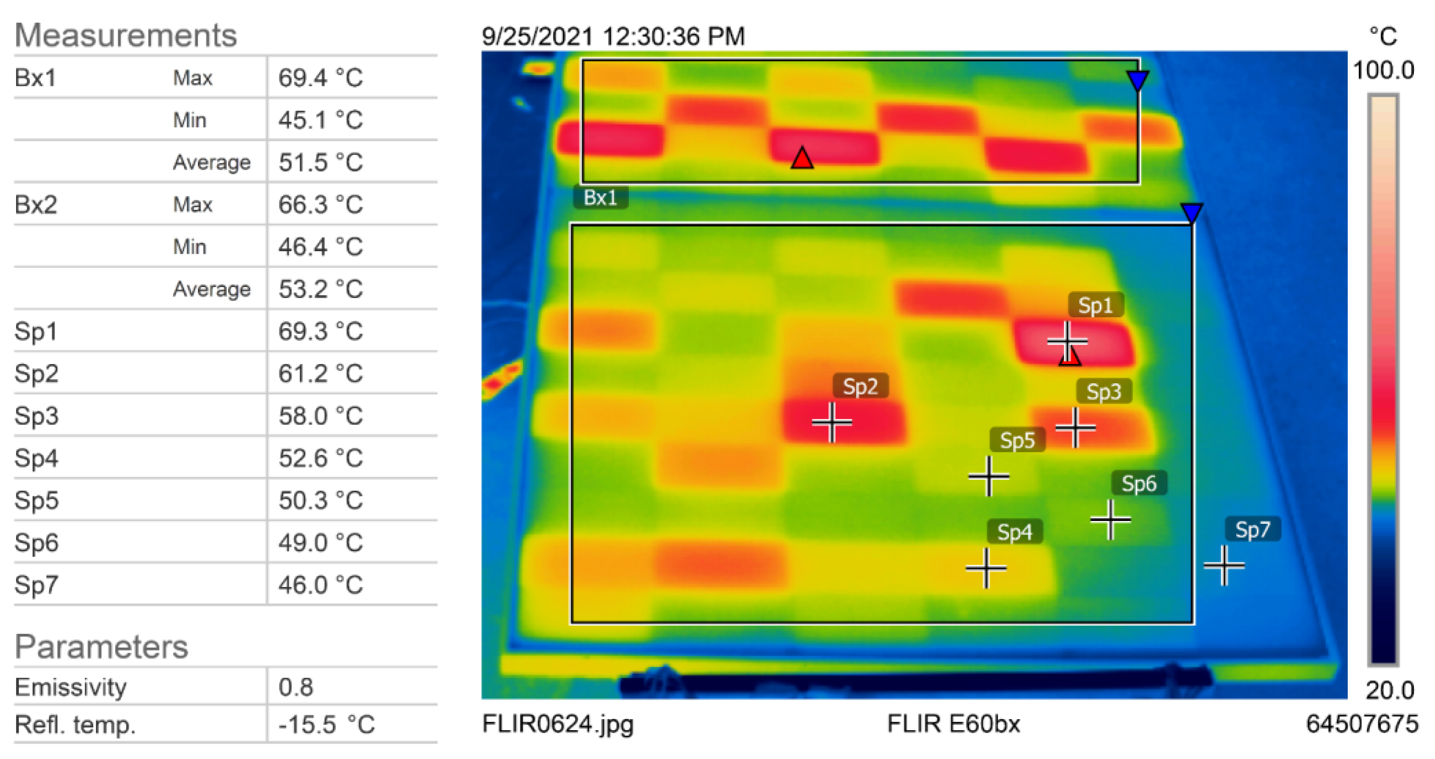
Figure 10.
Thermography analysis of the new module.
Figure 10.
Thermography analysis of the new module.
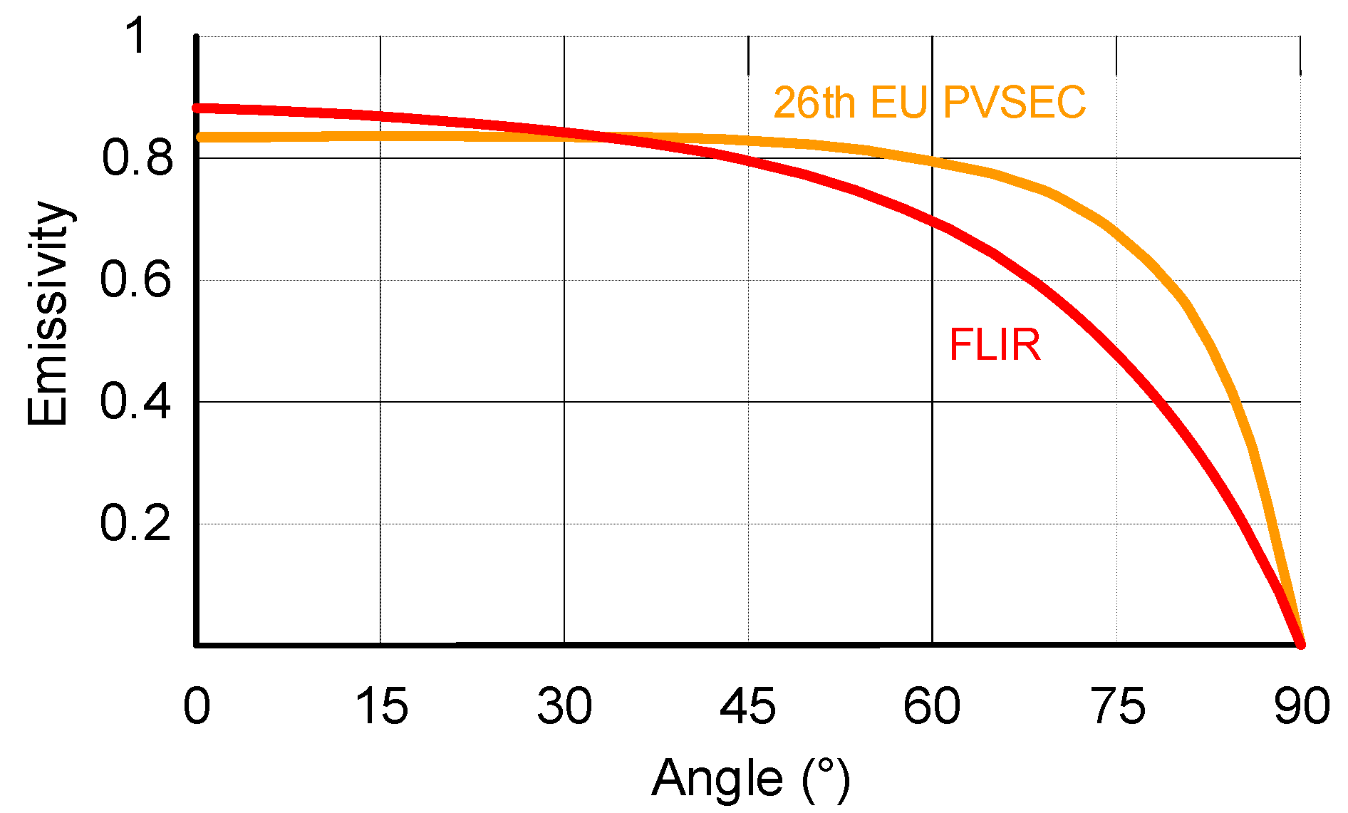
Figure 11.
Emissivity of glass as a function of reflection angle.
Figure 11.
Emissivity of glass as a function of reflection angle.
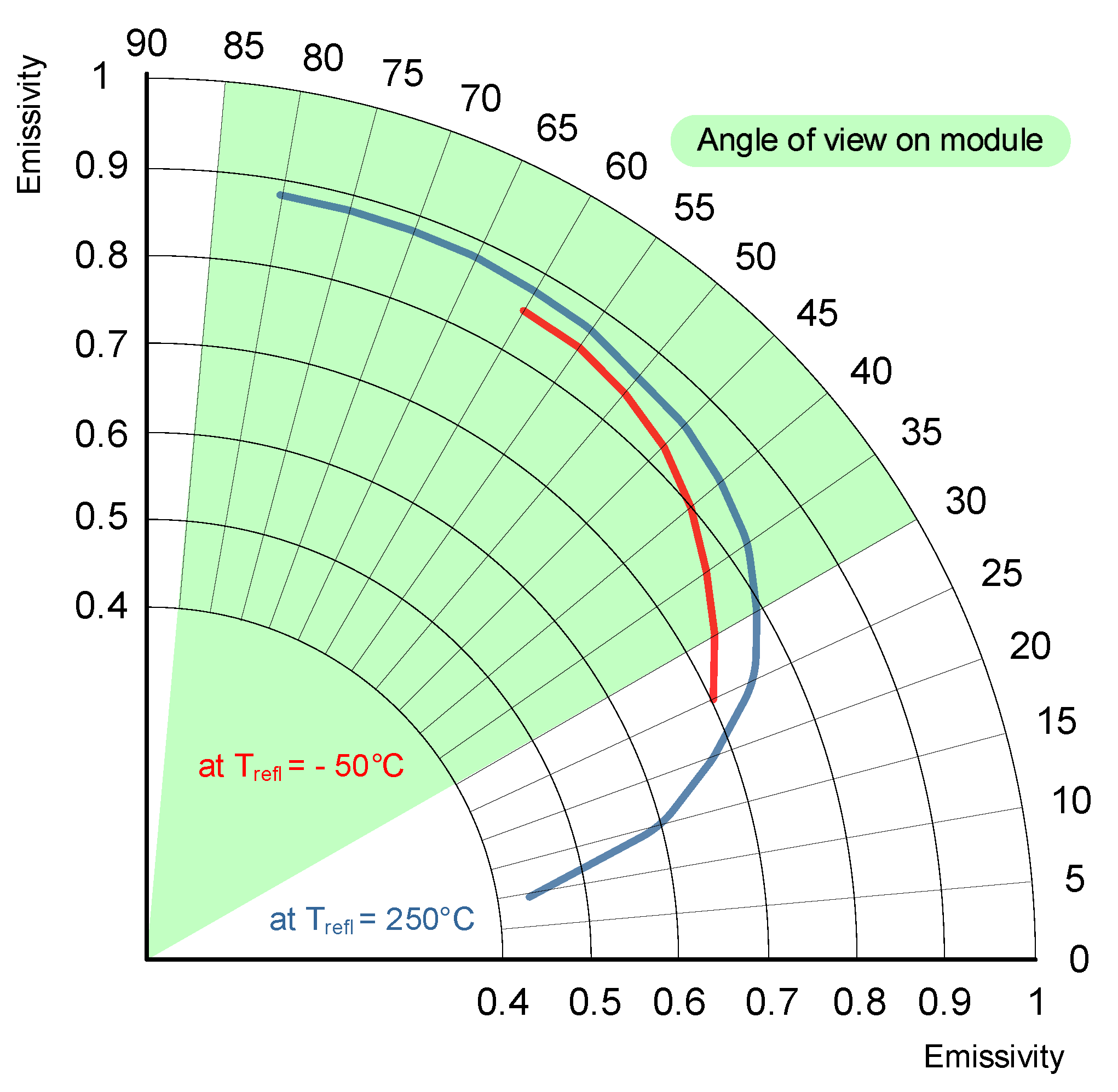
Figure 12.
Dependence of module emissivity on the shooting angle.
Figure 12.
Dependence of module emissivity on the shooting angle.
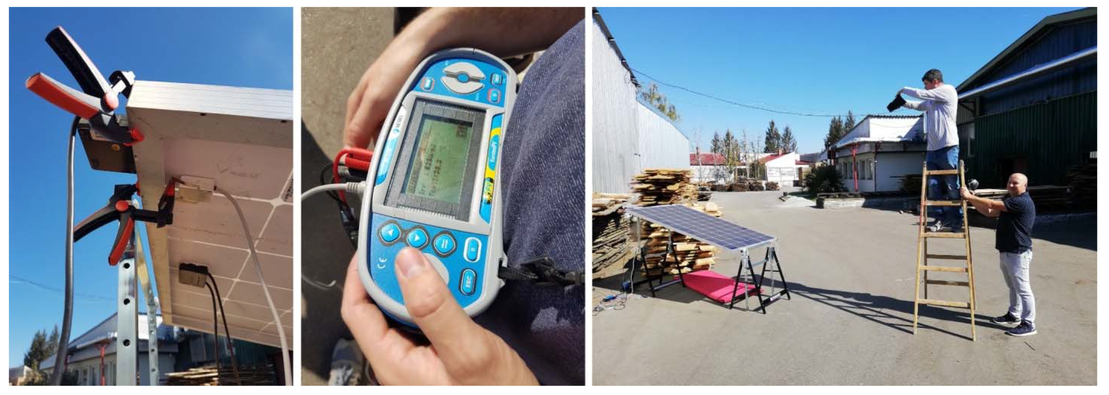
Figure 13.
Photo documentation of the measurement procedure.
Figure 13.
Photo documentation of the measurement procedure.
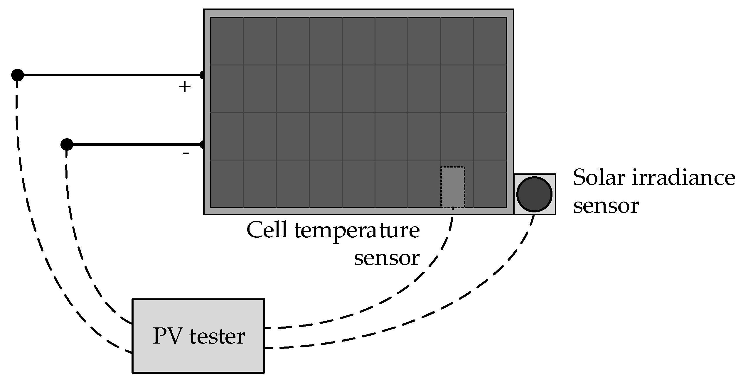
Figure 14.
PV module I-V curve measurement procedure with the PV tester.
Figure 14.
PV module I-V curve measurement procedure with the PV tester.
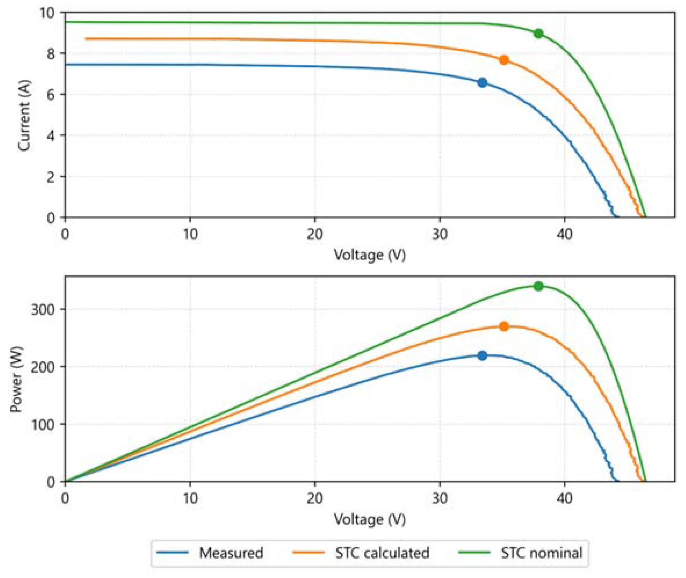
Figure 15.
I-V and P-V curves of the PV module 1 (washed).
Figure 15.
I-V and P-V curves of the PV module 1 (washed).
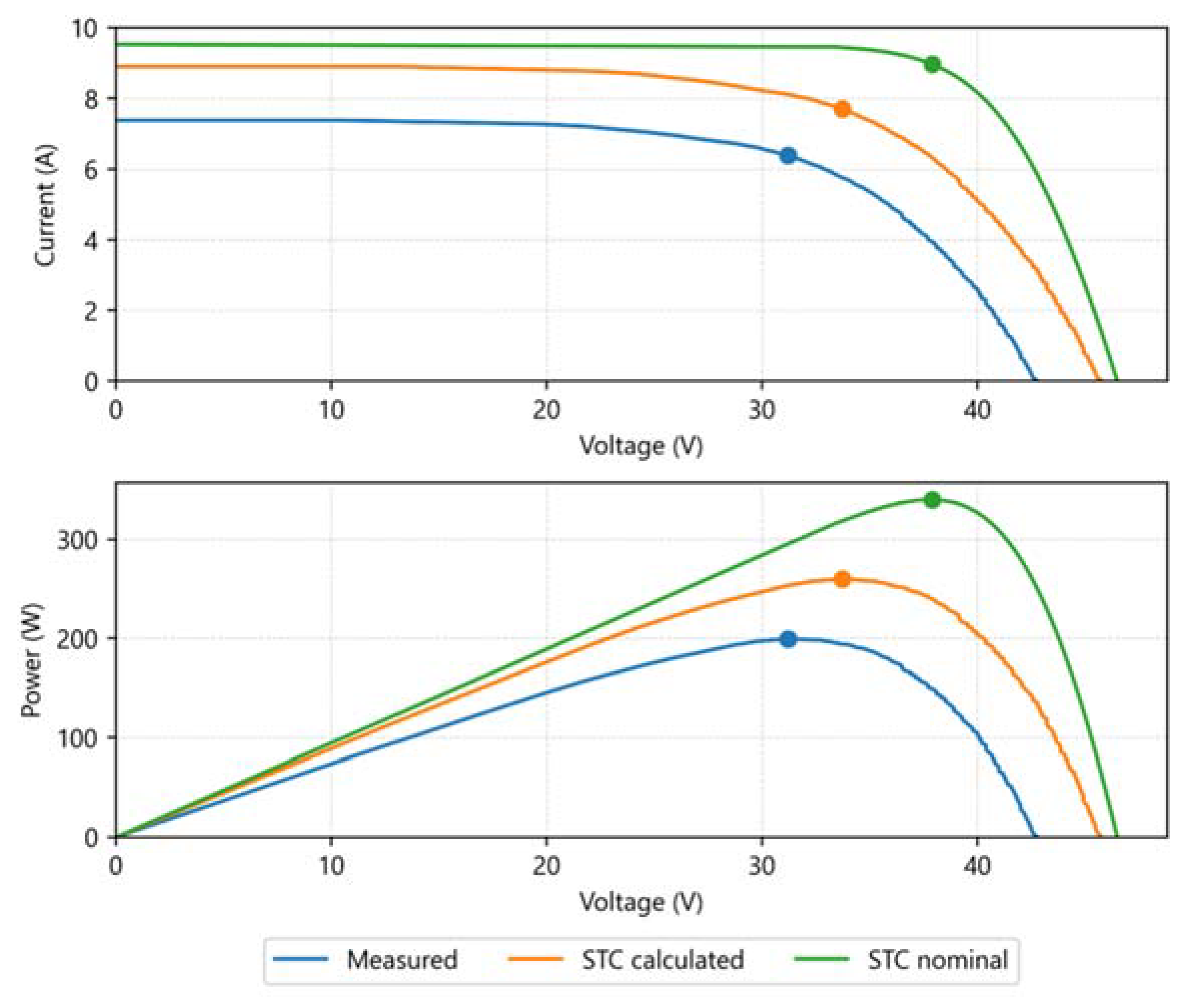
Figure 16.
I-V and P-V curves of the PV module 2 (washed).
Figure 16.
I-V and P-V curves of the PV module 2 (washed).
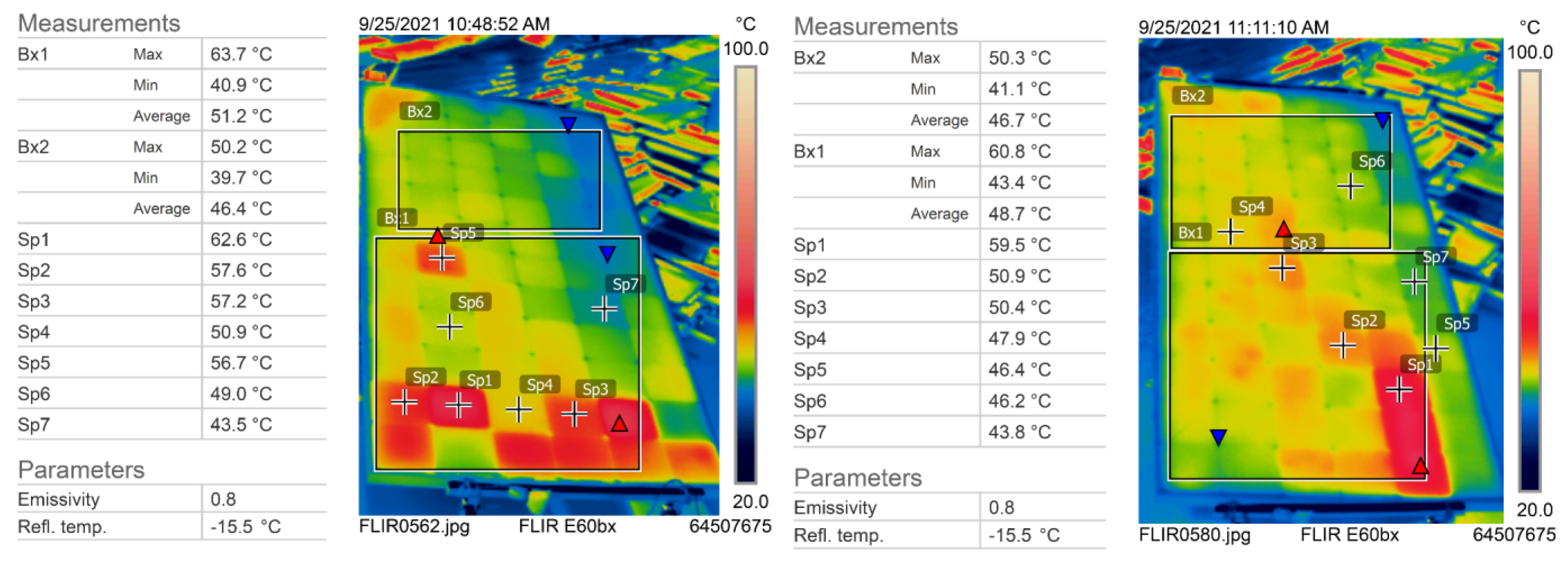
Figure 17.
Thermographic analysis of the PV module 1 before and after washing.
Figure 17.
Thermographic analysis of the PV module 1 before and after washing.
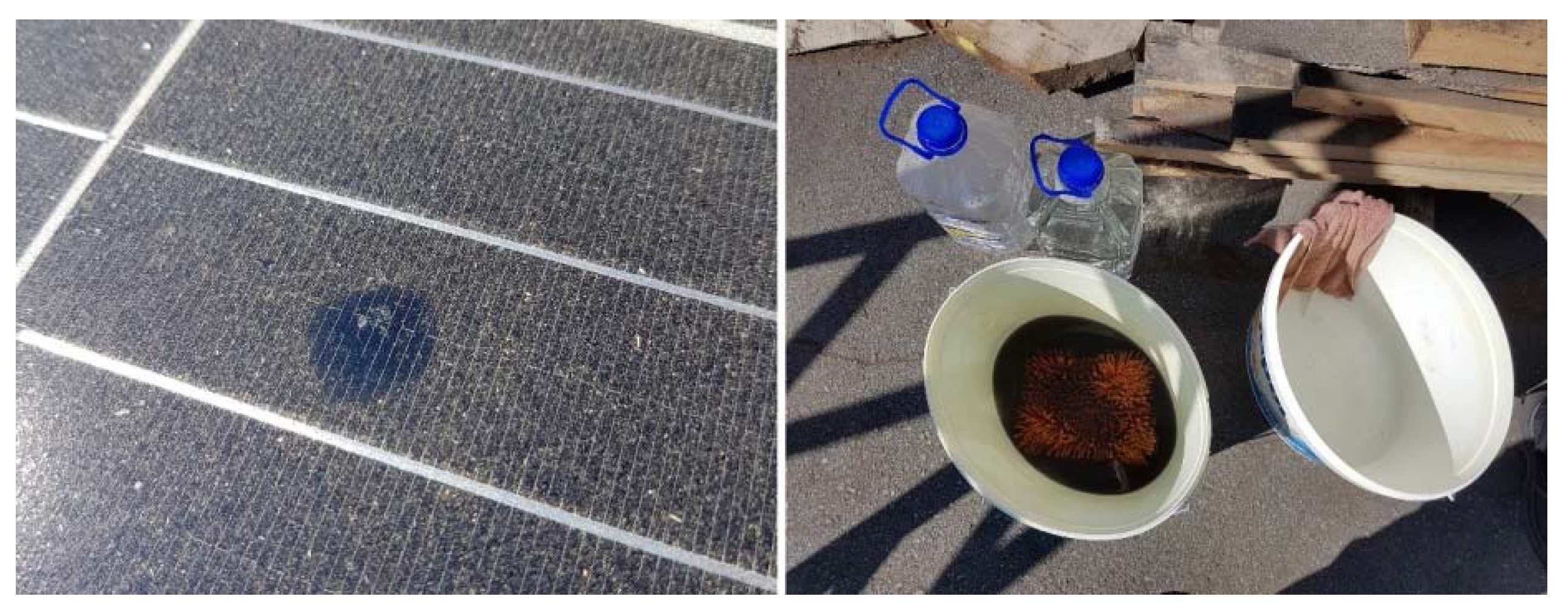
Figure 18.
Dusted PV module appearance and washing equipment used for cleaning.
Figure 18.
Dusted PV module appearance and washing equipment used for cleaning.
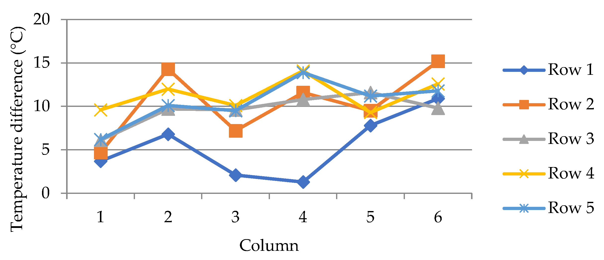
Figure 19.
Change in cell temperature of the first five rows of module.
Figure 19.
Change in cell temperature of the first five rows of module.
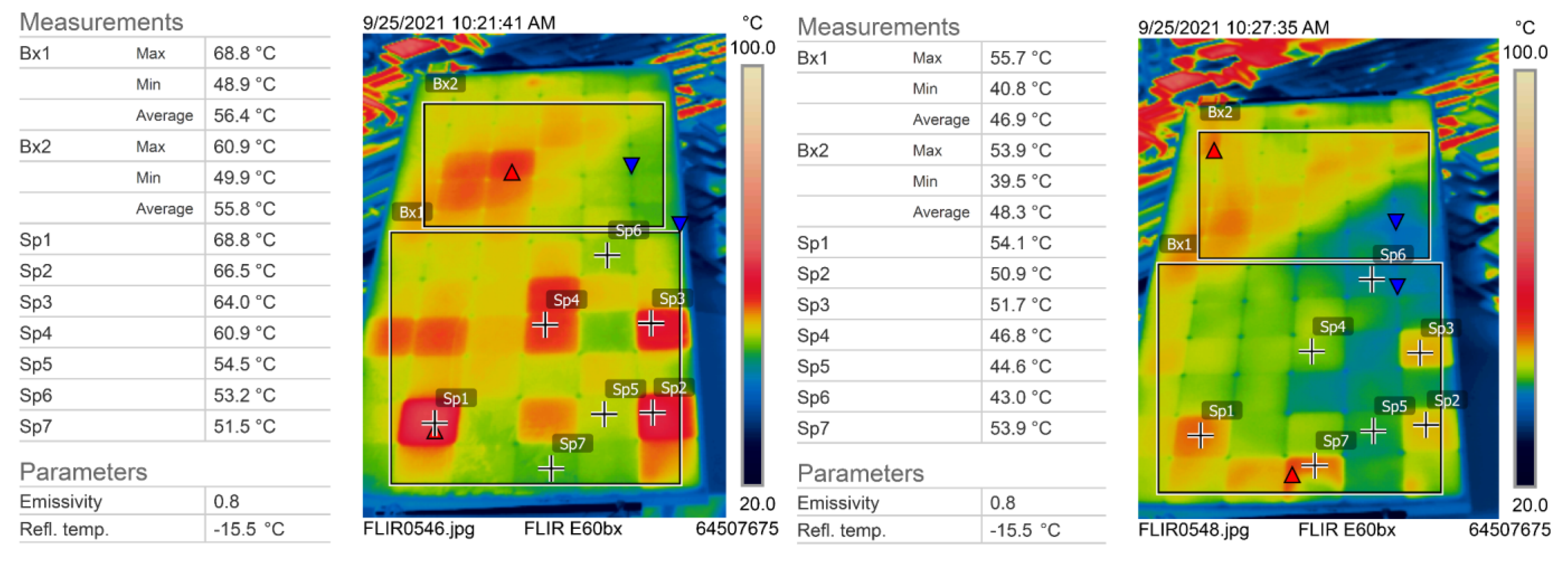
Figure 20.
Thermographic analysis of module number 2 (left) and number 3 (right).
Figure 20.
Thermographic analysis of module number 2 (left) and number 3 (right).
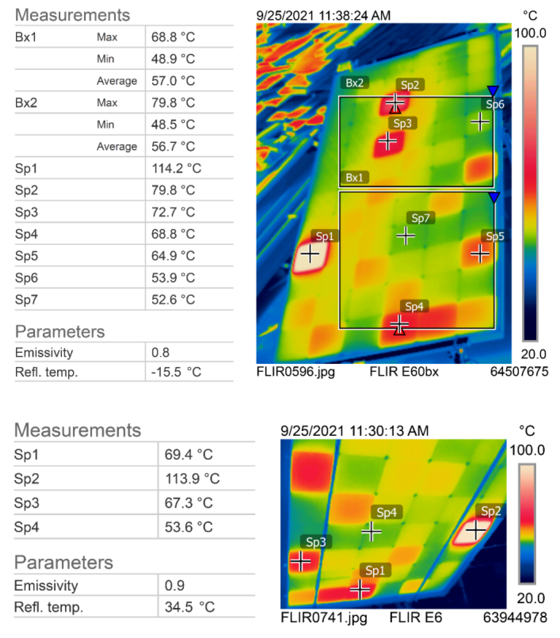
Figure 21.
Thermographic analysis of the frontside (up) and backside (down) of module number 4.
Figure 21.
Thermographic analysis of the frontside (up) and backside (down) of module number 4.
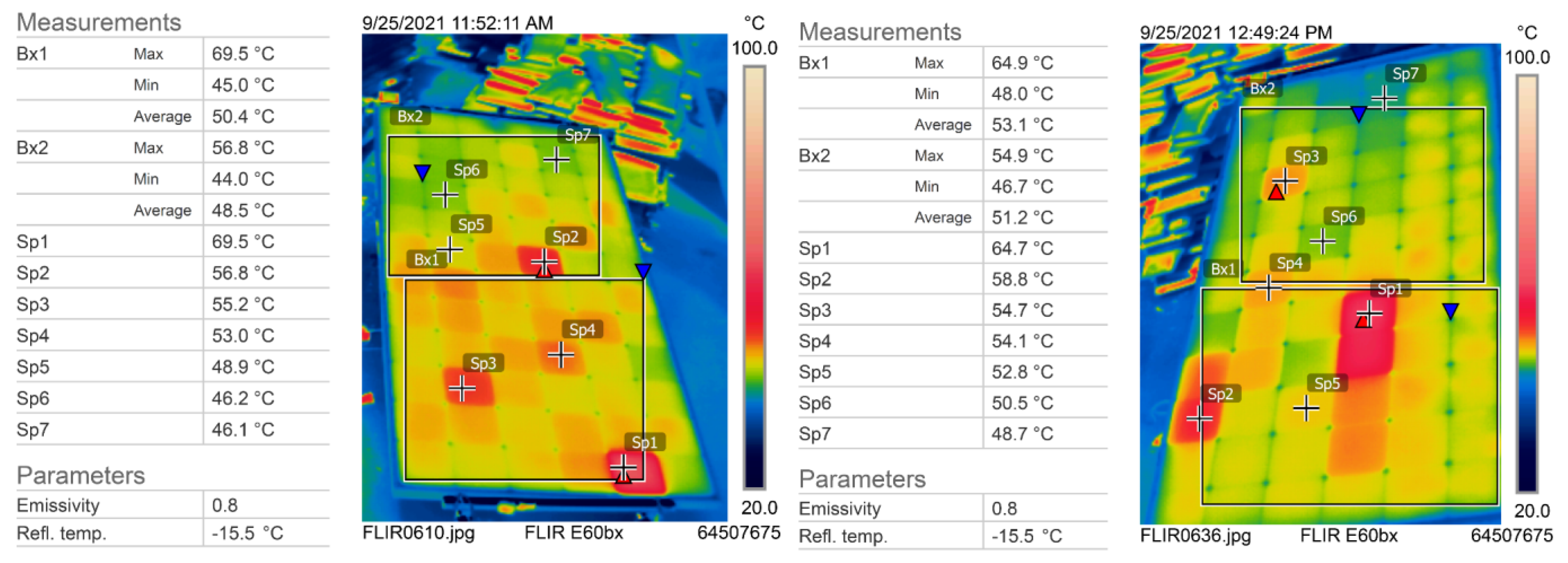
Figure 22.
Thermographic analysis of module number 5 (left) and module number 6 (right).
Figure 22.
Thermographic analysis of module number 5 (left) and module number 6 (right).
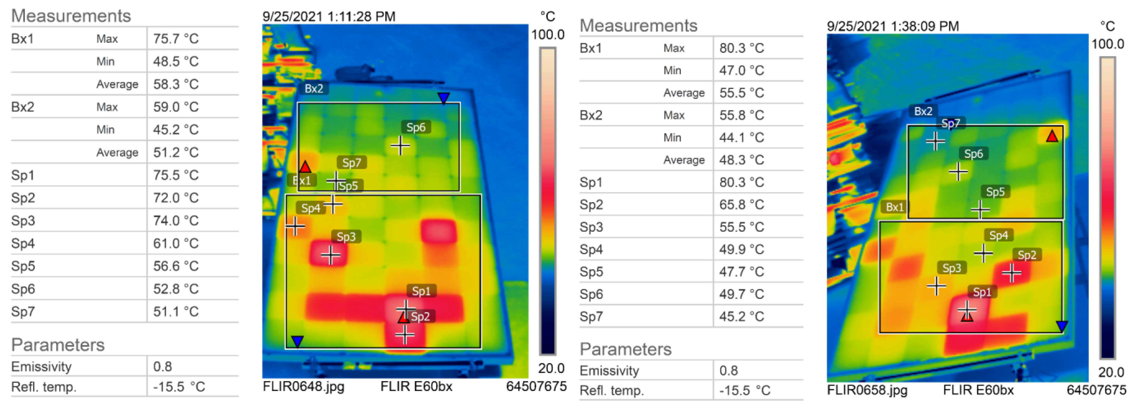
Figure 23.
Thermographic analysis of module number 7 (left) and module number 8 (right).
Figure 23.
Thermographic analysis of module number 7 (left) and module number 8 (right).
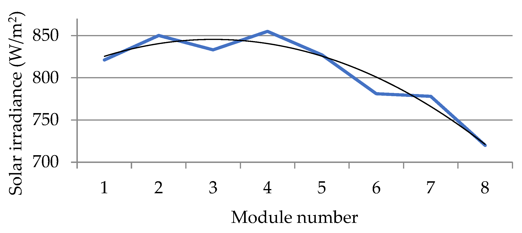
Figure 24.
Graphical representation of the solar irradiance over thermographic measurements on the modules.
Figure 24.
Graphical representation of the solar irradiance over thermographic measurements on the modules.
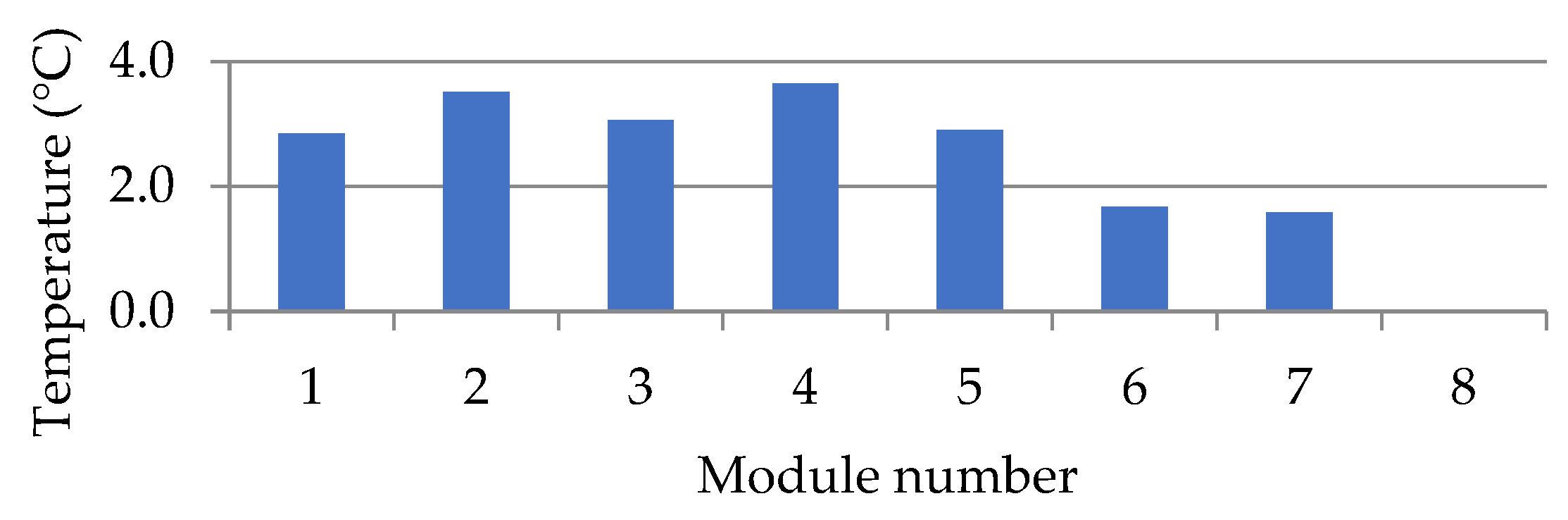
Figure 25.
Temperature correction values for equalization of the results due to the influence of different amounts of solar irradiance.
Figure 25.
Temperature correction values for equalization of the results due to the influence of different amounts of solar irradiance.
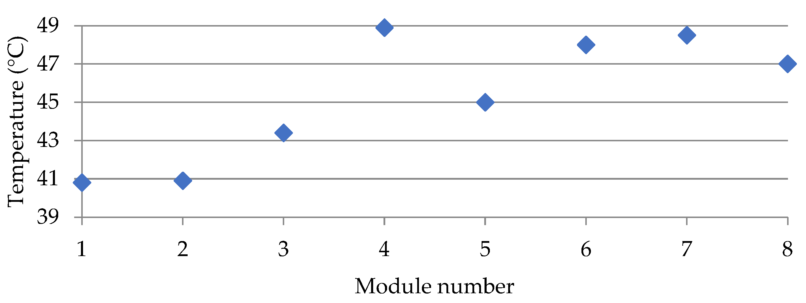
Figure 26.
Minimum temperature of modules during measurements.
Figure 26.
Minimum temperature of modules during measurements.
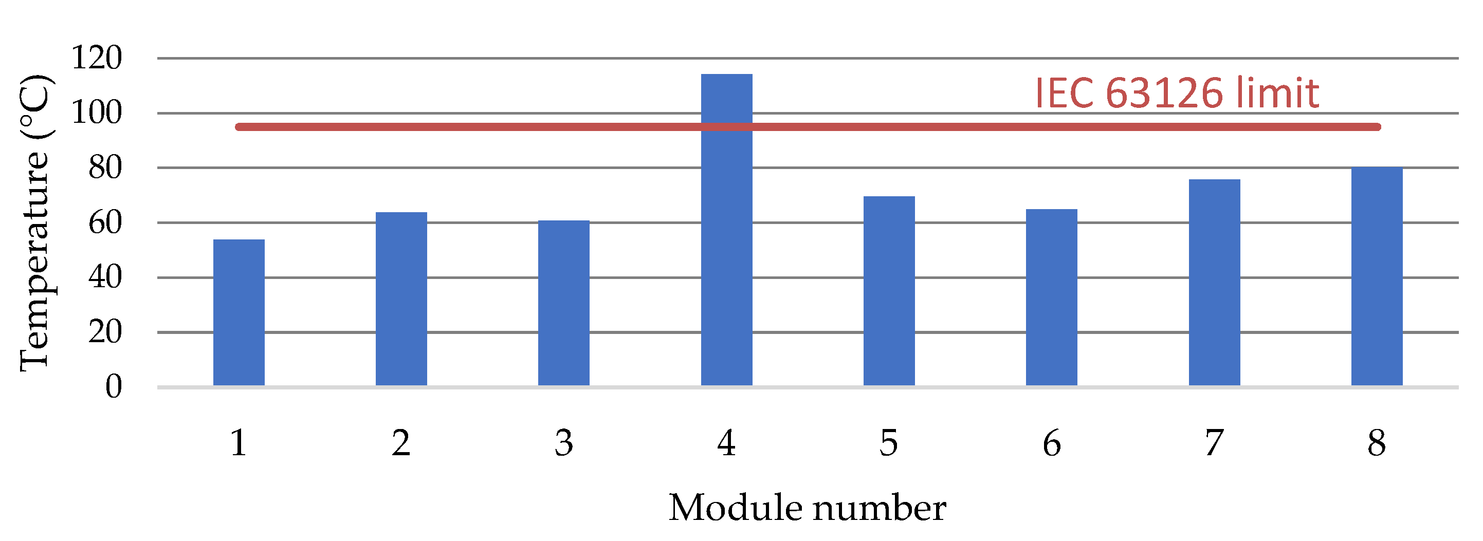
Figure 27.
Maximum temperature values of the module surface.
Figure 27.
Maximum temperature values of the module surface.
Figure 28.
Observed damage determined by visual inspection of the module.
Figure 28.
Observed damage determined by visual inspection of the module.
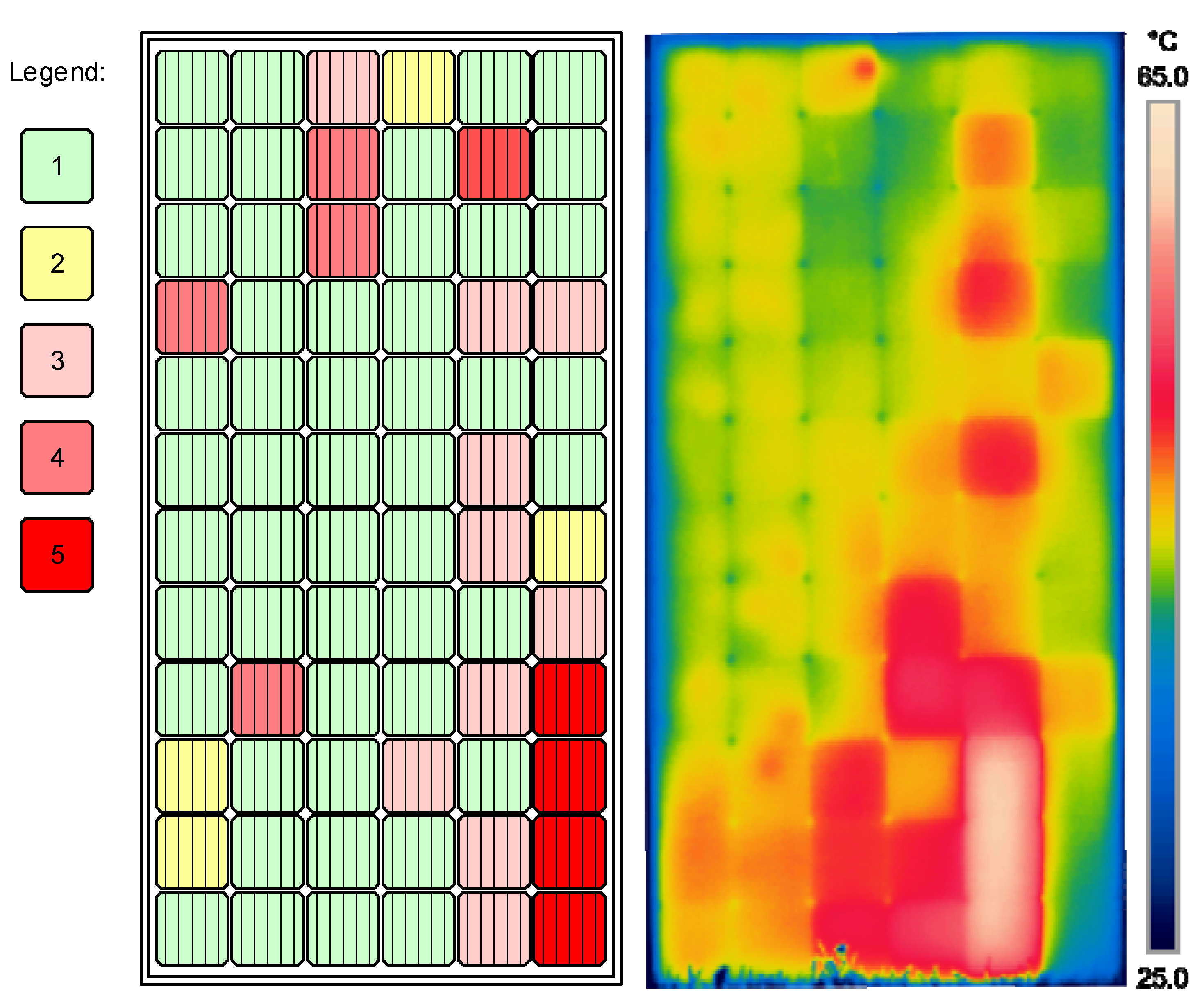
Figure 29.
Damage classification by visual inspection (left) and thermogram (right) of module number 3.
Figure 29.
Damage classification by visual inspection (left) and thermogram (right) of module number 3.
Table 1.
Technical characteristics of the original 340 Wp monocrystalline silicon PV modules.
Table 1.
Technical characteristics of the original 340 Wp monocrystalline silicon PV modules.
| Model | GSPV M6-340 | JAM60S10-345/MR |
|---|
| Cell number | 72 (6 × 12) | 120 (6 × 20) |
| Maximum static load, front side (ex. snow, wind) | 5400 Pa | 5400 Pa |
| Maximum static load, back side (ex. wind) | 2400 Pa | 2400 Pa |
| Glass | 3.2 mm tempered glass | n/a |
| Encapsulant type | Ethylene vinyl acetate | n/a |
| Nominal output power 1 | 340 Wp | 345 Wp |
| Cell efficiency 1 | 19.83% | 20.5 % |
| Open-circuit voltage 1 | 46.49 V | 41.76 V |
| MPP voltage 1 | 37.8 V | 34.99 V |
| Short-circuit current 1 | 9.53 A | 10.54 A |
| MPP current 1 | 8.99 A | 9.86 A |
| Current temperature coefficient | +0.06%/K | +0.044%/K |
| Voltage temperature coefficient | −0.32%/K | −0.272%/K |
| Power temperature coefficient | −0.45%/K | −0.354%/K |
| Dimensions | 1956 × 992 × 40 mm | 1689 × 996 × 35 mm |
Table 2.
Comparison of FLIR E60bx and E6 specifications.
Table 2.
Comparison of FLIR E60bx and E6 specifications.
| Camera | Flir E60bx | Flir E6 |
|---|
| IR resolution | 320 × 240 pixels | 160 × 120 pixels |
| Thermal sensitivity/NETD | <0.045 °C @ +30 °C/45 mK | <0.06 °C/<60 mK |
| Field of view (FOV) | 25° × 19° | 45° × 34° |
| Minimum focus distance | 0.4 m | 0.5 m |
| Spatial resolution (IFOV) | 1.36 mrad | 5.2 mrad |
| Spectral range | 7.5–13 μm | 7.5–13 μm |
| Object temperature range | –20 °C to +120 °C | –20 °C to +250 °C |
Accuracy
| ±2 °C or ±2% of reading, for ambient temperature 10 °C to 35 °C | ±2 °C or ±2% of reading, for ambient temperature 10 °C to 35 °C |
| Built-in digital camera | 3.1 Mpixel (2048 × 1536),
FOV 53° × 41° | 0.3 Mpix (640 × 480)
FOV 55° × 43° |
Table 3.
Comparison of the apparent temperature of the glass surface and the temperature of the plastic substrate of the module.
Table 3.
Comparison of the apparent temperature of the glass surface and the temperature of the plastic substrate of the module.
| | E60bx | E6 | E60bx-E6 |
|---|
| T (°C) | Backplate | Glass | Temperature Difference (ΔT) | Backplate | Glass | Temperature Difference (ΔT) | Backplate | Glass |
|---|
| max | 50.9 | 47.1 | 3.8 | 50.1 | 54.4 | −4.3 | 0.8 | −7.3 |
| min | 49.0 | 42.7 | 6.3 | 48.3 | 52.4 | −4.1 | 0.7 | −9.7 |
| Bx1 | 50.3 | 43.9 | 6.4 | 49.3 | 53.7 | −4.4 | 1.0 | −9.8 |
| max | 54.3 | 49.4 | 4.9 | 53.6 | 57.3 | −3.7 | 0.7 | −7.9 |
| min | 46.5 | 42.8 | 3.7 | 44.9 | 52.3 | −7.4 | 1.6 | −9.5 |
| El1 | 50.9 | 45.0 | 5.9 | 50.0 | 54.4 | −4.4 | 0.9 | −9.4 |
| S1 | 53.7 | 48.6 | 5.1 | 53.5 | 56.7 | −3.2 | 0.2 | −8.1 |
| S2 | 54.2 | 48.1 | 6.1 | 52.9 | 57.2 | −4.3 | 1.3 | −9.1 |
| S3 | 51.6 | 44.4 | 7.2 | 50.6 | 54.8 | −4.2 | 1.0 | −10.4 |
Table 4.
Temperature indicators of pilot PV module test.
Table 4.
Temperature indicators of pilot PV module test.
| Module temperature | 46.6 °C |
| Average cell temperature | 51.0 °C |
| Maximum cell temperature | 54.0 °C |
| Minimum cell temperature | 48.0 °C |
| Cell temperature difference | 6.0 °C |
| Module maximum temperature difference | 7.4 °C |
Table 5.
Distribution of the apparent temperature value of the new (reference) PV module.
Table 5.
Distribution of the apparent temperature value of the new (reference) PV module.
| | Column |
|---|
| 1 | 2 | 3 | 4 | 5 | 6 |
|---|
| Row | 1 | 41.9 | 42.7 | 42.4 | 42.4 | 42.4 | 41.4 |
| 2 | 43.4 | 43.5 | 43.5 | 43.2 | 43.5 | 42.6 |
| 3 | 43.5 | 43.4 | 43.4 | 43.6 | 43.4 | 43.4 |
| 4 | 44.2 | 43.4 | 42.6 | 44.4 | 44.4 | 43.4 |
| 5 | 47.3 | 44.7 | 50.0 | 44.0 | 44.2 | 43.1 |
| 6 | 45.6 | 47.0 | 46.4 | 45.2 | 43.6 | 45.5 |
| 7 | 51.3 | 45.7 | 49.7 | 45.7 | 46.3 | 43.9 |
| 8 | 46.7 | 54.7 | 47.1 | 55.5 | 48.4 | 53.8 |
| 9 | 61.0 | 49.6 | 62.1 | 48.0 | 58.5 | 46.1 |
| 10 | 46.7 | 46.6 | 46.7 | 46.2 | 48.2 | 46.6 |
| 11 | 48.7 | 48.9 | 48.9 | 48.4 | 47.2 | 46.2 |
| 12 | 50.9 | 49.8 | 50.7 | 49.8 | 51.9 | 46.8 |
| 13 | 50.2 | 51.1 | 50.1 | 58.8 | 54.1 | 47.2 |
| 14 | 56.2 | 49.6 | 53.6 | 49.6 | 68.9 | 47.2 |
| 15 | 49.9 | 50.6 | 56.4 | 50.1 | 51.1 | 47.0 |
| 16 | 54.1 | 53.0 | 60.9 | 50.7 | 57.9 | 47.2 |
| 17 | 49.3 | 55.5 | 49.9 | 50.5 | 49.1 | 47.0 |
| 18 | 49.6 | 50.2 | 49.3 | 49.2 | 49.3 | 46.3 |
| 19 | 54.6 | 57.1 | 51.9 | 52.8 | 47.9 | 46.0 |
| 20 | 52.1 | 48.8 | 49.7 | 48.4 | 47.3 | 44.8 |
Table 6.
Statistical data of the apparent temperature of the new module.
Table 6.
Statistical data of the apparent temperature of the new module.
| Module temperature | 41.0 °C |
| Average cell temperature | 48.6 °C |
| Maximum cell temperature | 68.9 °C |
| Minimum cell temperature | 41.4 °C |
| Cell temperature difference | 27.5 °C |
| Module maximum temperature difference | 27.9 °C |
Table 7.
Allocation in classes of abnormalities.
Table 7.
Allocation in classes of abnormalities.
| Class of Abnormality (CoA) | 1 (No Abnormalities—OK) | 2 (Thermal Abnormality—tA) | 3 (Safety Relevant Thermal Abnormality—dtA) |
|---|
| Recommendation for actions | No imminent action | Checking the cause and, if necessary, rectification in a reasonable period | Prompt interruption of operation, checking the cause and rectification in a reasonable period |
Table 8.
PV tester I-V curve measurement module technical characteristics.
Table 8.
PV tester I-V curve measurement module technical characteristics.
| Parameter | Measuring Range |
|---|
| DC voltage | 0–999 V |
| DC current | 0–15 A |
| DC power | 0–15,000 W |
| Solar irradiance | 0–1750 W/m2 |
| Cell temperature | −10–85 °C |
Table 9.
Environmental conditions at the moment of the I-V curve measurements.
Table 9.
Environmental conditions at the moment of the I-V curve measurements.
| PV Module No. | Solar Irradiance | PV Module Temperature |
|---|
| 1 | 821 W/m2 | 44.3 °C |
| 2 | 850 W/m2 | 37.3 °C |
Table 10.
PV module 2 (washed) I-V curve test results.
Table 10.
PV module 2 (washed) I-V curve test results.
| Parameter | Measured | STC Calculated | STC Nominal | Deviation |
|---|
| Open-circuit voltage | 42.80 V | 45.78 V | 46.50 V | −1.55% |
| Short-circuit current | 7.38 A | 8.90 A | 9.53 A | −6.61% |
| MPP voltage | 31.20 V | 33.72 V | 37.80 V | −10.79% |
| MPP current | 6.39 A | 7.71 A | 8.99 A | −14.24 |
| Fill factor | 63.12% | 63.81% | 76.68% | −12.87% |
| MPP power | 199.37 W | 259.9 W | 340 W | −23.56% |
Table 11.
PV module 1 (washed) I-V curve test results.
Table 11.
PV module 1 (washed) I-V curve test results.
| Parameter | Measured | STC Calculated | STC Nominal | Deviation |
|---|
| Open-circuit voltage | 44.30 V | 46.36 V | 46.50 V | −0.30% |
| Short-circuit current | 7.45 A | 8.71 A | 9.53 A | −8.60% |
| MPP voltage | 33.40 V | 35.13 V | 37.80 V | −7.06% |
| MPP current | 6.57 A | 7.68 A | 8.99 A | −14.57% |
| Fill factor | 66.49% | 66.82% | 76.68% | −9.86% |
| MPP power | 219. 44 W | 269.84 W | 340 W | −20.64% |
Table 12.
Solar irradiance and module temperature at the time of the measurement.
Table 12.
Solar irradiance and module temperature at the time of the measurement.
| Module | 1 | 2 | 3 | 4 | 5 | 6 | 7 | 8 |
|---|
| W/m2 | 825 | 850 | 833 | 855 | 827 | 781 | 778 | 720 |
| T (°C) | 38.3 | 37.3 | 34.8 | 41.8 | 45.3 | 39.3 | 40.3 | 41.3 |
Table 13.
Numerical data comparison of the thermographic analysis.
Table 13.
Numerical data comparison of the thermographic analysis.
| Module Number | 1 | 2 | 3 | 4 | 5 | 6 | 7 | 8 | Average |
|---|
| Minimum temperature [°C] | 40.8 | 40.9 | 43.4 | 48.9 | 45.0 | 48.0 | 48.5 | 47.0 | 45.3 |
| Maximum temperature [°C] | 55.7 | 63.7 | 60.8 | 69.8 | 69.5 | 64.9 | 75.7 | 66.0 | 65.8 |
| Difference [°C] | 14.9 | 22.8 | 17.4 | 20.9 | 24.5 | 16.9 | 27.2 | 19.0 | 20.5 |
| Percentage difference [%] | 36.52 | 55.75 | 40.09 | 42.74 | 54.44 | 35.21 | 56.08 | 40.43 | 45.16 |
| Measurement time [h] | 10:27 | 10:48 | 11:11 | 11:38 | 11:52 | 12:49 | 13:11 | 13:38 | |


