Abstract
Nowadays, hydraulic excavators are an indispensable part of the construction industry; however, conventional hydraulic excavators consume a great deal of fossil fuel and release a large amount of pollution emissions into the environment. This causes many unwanted costs, therefore, effective solutions are required to solve the above-mentioned problems. In this paper, a new independent metering system is proposed to improve energy-saving and reduce costs of a conventional system. In detail, a directional valve is used to control movement and three electro-hydraulic poppet valves are integrated to adjust the flow rate at the inlet and outlet ports of the boom cylinder. In addition, a control strategy based on the coordination between the speed of the pump and the opening area of the spool valve is designed to improve the performance of the system. Specifically, the valves are controlled based on the strategy that the meter-in valve is opened fully to reduce throttling losses and that the meter-out valve is controlled to reduce leakage. The speed of the pump is adjusted according to the feedback position signal. To demonstrate the effectiveness of the new configuration, a real test bench of the boom system was built under laboratory conditions. From the experimental results, the new independent metering valve system not only works with a high tracking precision, but it also reduces energy consumption. Compared with a conventional independent metering system, the fuel economy of the proposed structure can achieve a reduction of approximately 6.5%.
1. Introduction
Hydraulic systems are usually applied to construction machinery and are widely used in industry, such as for excavation, construction, and agriculture systems. Due to their high power-to-size ratio and robustness, hydraulic systems are considered to be the perfect alternative to electrical actuators that require high power. Among these, hydraulic excavators are the most generally used [1,2,3]; however, conventional excavators consume a great deal of fossil fuel, which are gradually being depleted. Moreover, the emissions from conventional excavators emit harmful gases into the environment, which cause problems related to air pollution and global warming [4]. Hence, reducing energy consumption is presently an urgent issue for excavators [5,6,7,8,9,10,11,12].
Regarding energy consumption problems, a conventional excavator is controlled by electro-hydraulically directional spool valves, in which four-way proportional directional control valves are the most popular. However, these directional valves cause a high energy loss of approximately 30% through many factors, such as high-pressure margin, throttling loss, and load differential. In addition, the leakage and friction in the pumps and pipelines are also elements that motive energy loss in conventional excavators [13,14,15,16], leading to increasing costs during system operation. Hence, to achieve the desired performance in terms of cost- and energy-saving, an independent metering valve system (IMV) has been developed [17,18,19,20].
A conventional independent metering valve (CIMV) configuration uses four proportional valves (2/2-way-proportional valve) or an electro-hydraulic poppet valve (EHPV) and a check valve. In detail, two valves are connected to the inlet and the other two valves are located at the outlet of the cylinder. A check valve is placed on the tank return line (as shown in Figure 1). The valves are independently controlled according to different working modes, which represent flexible operations and energy-consumption optimization in the system. In addition, a regeneration mode in the CIMV system operates without a flow from the pump. Thus, the energy consumption of the CIMV system is lower than that of the conventional excavator, which has been proven by numerous research projects and patents [21,22,23,24,25,26]. However, controlling four proportional valves is not simple when they depend on a pressure difference between the inlet and outlet of the valves, which leads to poor performance in valve control. To overcome this problem, Tabor developed a mathematical model of a hydraulic system using four independent metering valves with an optimal valve coefficient ratio. The experiment results indicated that the velocity errors of the valves could be reduced [27]. Nevertheless, using an equivalent valve coefficient equation is a complicated approach because it causes difficulties in terms of programming and control. Moreover, another significant disadvantage of this system is that the regenerative and pumped flows are combined directly, resulting in a difficult conservation of regenerative energy. Using a different approach, Choi proposed a valve conductance method, which was computed using the desired flow and pressure difference across the valve. After that, it is combined with the characteristic curves of EHPV to exactly determine the control valve signal [28]. This approach ensures that the cylinder operates at its design speed in the experimental environment; in reality, however, valves always leak due to pressure changes during operation. Therefore, closed-loop control methods to compensate for leakage are widely used for controlling proportional valves [29,30,31,32].
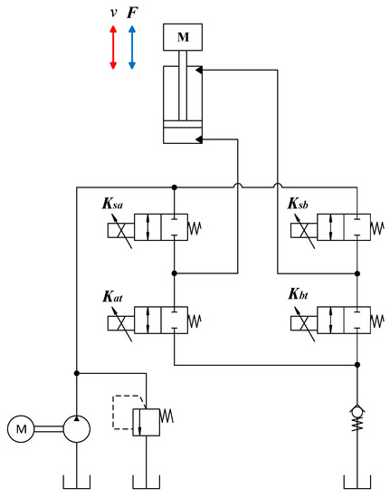
Figure 1.
The conventional independent metering valve system.
The CIMV system has great benefits in terms of energy-savings for hydraulic excavators and provides more flexibility in designing a control strategy, but using four EHPV circuits to control one actuator is an expensive approach. In recent years, some studies have focused on reducing the number of proportional valves and simplifying the control process of the system, as well as on developing new control strategies. Different strategies using pump/valve coordinate controls with two 4/3-way proportional directional valves for the IMV system, one for meter-in control and another for the meter-out control have been developed [33,34,35,36]. These studies take advantage of combining the pump control into the IMV system to smoothen system operation and save energy. Although the number of proportional valves is decreased, the use of proportional directional valves is still an expensive solution compared to EHPV though their functions are almost the same. In another study, a new configuration of a single metering edge was presented [13], where only one proportional valve (2/2-way-proportional valve) was used with a function of a meter-out valve. Moreover, the combined control algorithm for the meter-out valve and pump was developed with improved energy-savings and auxiliary functions, such as anti-flow overload and overload protection. Hence, this system can achieve low operational costs and an energy-consumption reduction. However, the control method of this system is highly complex with many levels of control for the pump and valves; this could cause instability and difficulty for the operator.
Considering the high cost of the IMV system, Ahamad et al. proposed a new IMV (NIMV) circuit that replaced the expensive proportional directional valve with a cheaper directional valve [37]. This study explained the working principle of the NIMV system under the different load conditions. Moreover, an equivalent valve coefficient equation was developed for this system. Based on the simulation results by the AMESim software, the energy savings of this system were higher than those of the CIMV system by 16.43% in the high-side regeneration extension mode and 63.63% in the low-side regeneration retraction mode. However, the equivalent valve coefficient equation is still complex and difficult to exactly control the flow rate through the valve. Simulation results are not sufficiently qualified to accurately evaluate the effectiveness of the NIMV system. Intensive experiments are required to have a more accurate view.
Based on the above reasons, in this paper, a coordinated pump–valve control strategy is proposed to improve energy-saving and displacement tracking precision. In detail, the velocity feed-forward and position feedback signals were used to control the valves. In addition, the pump speed command was calculated from the tracking error through a proportional integral derivative (PID) controller. To prove the effectiveness of the new IMV system with the proposed control strategy, a real test bench was built based on the proposed hydraulic circuit under laboratory conditions. Then, the proposed control strategy was verified in real-time. The experiment results of each metering mode were compared with equivalent modes using the CIMV system. The result shows that the NIMV can save energy by approximately 4% in the power extension mode, by 22% in the power retraction mode and by 6.5% in the high side regeneration extension mode. Moreover, the displacement tracking precision of the proposed IMV is higher than that of the CIMV.
2. New Independent Metering Configuration
To overcome the shortcomings of the CIMV circuit, a new NIMV configuration is shown in Figure 2a, in which three EHPVs (Ksa, Ksb, Kbt) and one directional valve (Kd) are logically linked together to control the cylinder. In this configuration, the NIMV can reduce the number of EHPVs, but still guarantees the same working modes as the CIMV configuration. Moreover, the NIMV does not have check valves for pressure maintenance in the low side regenerative modes, thus the power loss in these operating modes is minimized. The NIMV system has five metering modes, like the CIMV system; however, only four metering modes are used in this study. The load force in this study has the same direction as gravity. The CIMV system has a low side regeneration extension mode (LSRE) that requires the load force be in a different direction from gravity; therefore, the LSRE mode is neglected in this research. The four modes of the NIMV are shown in Figure 2b and the EHPV operation in each mode is shown in Table 1.
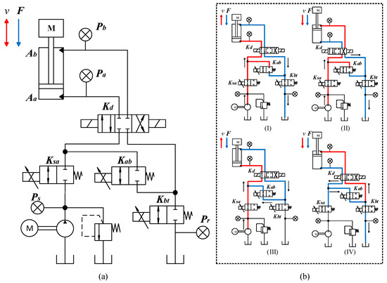
Figure 2.
(a) Configuration of an actuator using the new IMV circuit. (b) Four metering modes of the NIMV; (I) PE mode; (II) PR mode; (III) HSRE mode; (IV) LSRR mode.

Table 1.
Valve operation in each mode.
The power extension mode (PE) is described in Figure 2(b-I). In the PE mode, the bore chamber of the cylinder is supplied with the flow rate from the pump through the Ksa valve. The oil from the rod chamber goes to the tank through the Kbt valve. Directional valve Kd changes the position of the spool to adjust the direction of the flow to the cylinder. With the PE mode, the directional valve operates at the left position. Like the PE mode, the power retraction mode (PR) has the same working valve as the PE mode (shown in Figure 2(b-II)). The cylinder retracts when directional Kd valve operates at the right position, and the oil from the pump goes into the rod chamber through the Ksa valve. The oil from the bore chamber returns to the tank through the Kbt valve.
Operations of the high side regeneration extension mode (HSRE) is described in Figure 2(b-III). Different from the PE mode, the HSRE drives the cylinder with a high velocity. In these modes, returning oil from the rod chamber through the Kab valve combines with the supplied oil from the pump through the Ksa valve, and goes into the bore chamber. Therefore, a lager flow is supplied to the cylinder in the HSRE mode than in the PE mode, resulting in higher speeds during operation.
The low-side regeneration retraction mode (LSRR in Figure 2(b-IV)) allows the boom cylinder to move without using the flow rate from the pump. In the LSRR mode, the cylinder retracts under the effect of load and the gravitational force. The output flow rate from the bore chamber is reused through the Kab valve and pumped into the rod chamber during piston retraction. The excess flow rate due to differences in chamber volumes goes to the tank through the Kbt valve.
3. Control System Design
In this study, the NIMV system is applied to a boom test bench. The cylinder is assembled vertically with a fixed load. Thus, the potential of the regeneration mode can be effectively studied in practice. The working principle and the control strategy of the system are shown in Figure 3. To save energy and improve control performance, the coordinated control between the speed of the pump and opened area of valve is used. The pump has the role of ensuring that the required flow rate is supplied to the cylinder with a suitable amount of oil to reduce the energy consumption of the system. However, the operating speed of the motor is often very high, leading to large errors during operation. This makes it difficult for the pump to precisely control the desired position of the cylinder. Therefore, the valve that has the function of controlling the flow rate between the pump and the boom cylinder can ensure a better tracking performance of the cylinder. In the proposed control strategy, the meter-in valve is fully opened, and meter-out valve is controlled to combine the velocity feed-forward and position feedback (VFPB) [35,36]. In addition, the speed of the pump is controlled based on the position feedback control (PBC).
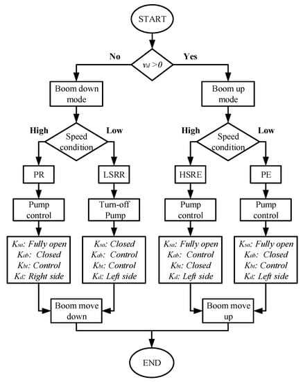
Figure 3.
NIMV control strategy for the boom system.
3.1. Valve Control
To reduce the throttle loss of the valve, the meter-in valve is opened to maximum and the meter-out valve is controlled using the VFPB method (shown in Figure 4). The maximum opened area of the meter-in valve decreases the throttling losses more compared to the meter-out valve [13]. The control valve signal, (K = sa, ab or bt), is combined with the velocity feed-forward control signal, , and the position feedback control signal, Upd, as given by Equation (1):
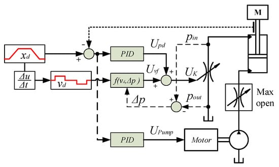
Figure 4.
Working principle of valve and pump control.
The velocity feed-forward control signal, , is obtained, as given by Equation (2):
where is the design velocity, is piston chamber area (x = a or b follow the mode operation), qN is flow rate through the EHPV under rated pressure difference , and is the pressure difference between the inlet and outlet of the EHPV.
Moreover, position feedback control signal with a proportional integral derivative (PID) controller is added to improve operation accuracy, as follows:
where is the design position and is the actual position of the cylinder.
3.2. Pump Control
During the moving up and down processes of the boom cylinder, the pump is controlled with the PBC method (shown in Figure 4). The speed of the motor is controlled by the signal that is obtained by the position of the feedback control, . With the PBC control for the pump, a suitable flow rate is provided for the cylinder chambers to ensure the stable operation of the cylinder. By combining the PBC and VFPB control, the position of the cylinder can achieve a good tracking performance. In addition, the energy consumption at the pump is also minimized. The is produced by a PID-controller, as given by Equation (4):
During the experiment, to reduce energy consumption and protect the pump, we recommend the following two operational strategies: (1) maintain the pressure Ps before starting to operate the valves; (2) turn off the pump when the cylinder extends to its maximum.
3.3. Energy Consumption
The energy consumption of the IMV system can be calculated by the energy consumption of the electric motor that drives the pump of the system. The energy consumption is calculated based on the feedback value of a speed sensor and a torque sensor installed in the system and is given as Equation (5):
where E is the energy consumption and and ω are the torque and angular velocity of the electric motor, respectively.
The energy consumption is used to evaluate the energy savings of the NIMV system and compared with the CIMV system in each case using Equation (6).
where is the energy savings, is the energy consumption of CIMV system, and ENMV is the energy consumption of NIMV system.
4. Experiments and Results
The hydraulic boom excavator system was built to evaluate the effectiveness of the NIMV system and was also compared with the CIMV system. The NIMV (circuit 7) and CIMV (circuit 6) were designed in parallel, and had the same connection with hydraulic cylinder 10 (placed on vertical) and pump 3, as shown in Figure 5. The transition of two controllers between two circuits was performed via a switch that was connected with three 4/2 directional valves (one valve for pump outlet 5, two valves for inlet 8, and outlet 9 of the cylinder). The EHPVs of the system were solenoid proportional valve SP10-24 from HydraForce. The control signal range for the EHPV was from 0 to 10 V, the signal was converted from 0 to 24 V via the amplifier and was then transferred to the EHPV. The diameter of the piston was 40 mm, the rod diameter was 20 mm with a stroke length of 500 mm, and the cylinder was affected by a fixed load of 100 kg. The linear sensor, TLH-0500, was added to measure the position of the cylinder, and a pressure sensor was added to measure the pressure value of the valve, cylinder, and pump outlet. The relief valve was set at 100 bar to guarantee the safety of the system during operation. The experiment parameters are listed in Table 2.
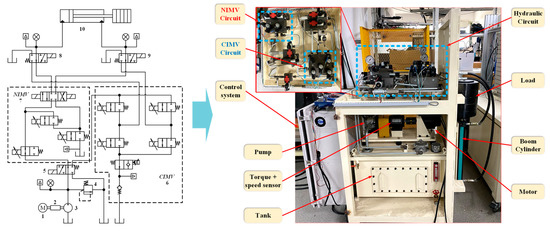
Figure 5.
The test bench of the hydraulic excavator boom system.

Table 2.
Experimental parameters for boom–excavator model.
4.1. Verification with Mode Control
From the working principle of the metering modes and the control strategy, two test cases for the boom system were conducted based on two main evaluation criteria: the working performance and energy-saving potential. The first case includes the experimental results from the NIMV system with four metering modes over one cycle to evaluate the proposed system’s performance. Meanwhile, the second test case was a comparison of energy-saving between the NIMV system and the CIMV system based on the same working conditions to prove the effectiveness of the proposed system.
The NIMV system’s experimental results are depicted in Figure 6, and show the working parameters of each mode, including the EHPV control signal, system pressure, and cylinder displacement. The PE mode begins from 1 to 9 s with a target velocity of 62.5 mm/s (the target velocity can be obtained by the derivative of the target position). In the initial state from 0 to 1 s, all valves are closed, only the pump runs to maintain the Ps pressure to protect the pump from returned pressure at the cylinder (in some cases, the initial position of the cylinder is not zero, so the system still maintains the Pa pressure before the pump opens). Under the coordinated control of the PBC and the VFPB, the actual displacement of the cylinder is stability controlled and reaches the target trajectory. The Ksa valve is fully open while the signal control of the Kbt valve increases quickly from 0 to 10 V at 2.5 s and drops gradually after that. The pump must deliver the necessary flow for the cylinder to move in the required trajectory when the PE mode is activated. Thus, the position feedback in the VFPB method increases the valve control signal, enabling the valve to open faster. Therefore, the loss at the valve is minimal, helping the cylinder reach the target speed faster. The cylinder moves to its maximum stroke length after 9 s, at that point the pump and all valves are closed to save energy and the position of the cylinder is maintained.
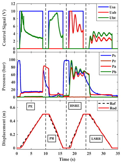
Figure 6.
The NIMV experimental results. (K = sa, ab or bt): control signal of Ksa, Kab, and Kbt valves. Ps: pressure at pump outlet; Pa, Pb: pressure at bore and rod chamber of cylinder, Pr: pressure at tank.
From 10 to 17 s, the PR mode is used for the cylinder to retract at a high speed (100 mm/s) because this mode is affected by both flow rate in the pump and the gravitational potential energy. Therefore, the Kbt valve plays a major role in adjusting the speed of the cylinder. However, a high speed can cause damage to the dampers and endanger the operator. In addition, when the cylinder moves down at a high speed, the flow rate from the pump goes to the rod chamber, which cannot keep up with the speed of the cylinder. Because the valve and pump are opened at the same time and the cylinder moves down as soon as the valve opens, the pump cannot provide the correct flow rate to the cylinder at that time; thus, the cylinder will draw oil from the pump. This is also the reason why pressure Ps is zero when the valve is open (shown in Figure 6). After that, the flow rate from the pump increases gradually and responds to the speed of the cylinder, so that the Ps pressure increases gradually until the position is zero.
After the PR mode ends, the pump is turned on to maintain pressure Ps before starting the HSRE mode. In the HSRE mode, the cylinder moves at the target velocity at 100 mm/s from 18 to 25 s. The response time of the cylinder in this mode is slower than in the PE mode, because when the valve opens, the oil is supplied into both cylinder chambers. It then takes a long time to create a thrust difference between the bore chamber and rod chamber. Moreover, the lifting load pressure of this mode is higher than that of the PE mode because the oil circulates in a closed circuit, which causes a high pressure in the system. This pressure is higher than the setting pressure on the relief valve, leading to loss of flow in the system. Hence, it causes a higher energy consumption than in the PE mode (energy consumption of the PE and HSRE modes is shown in Figure 7 in Section 4.2).
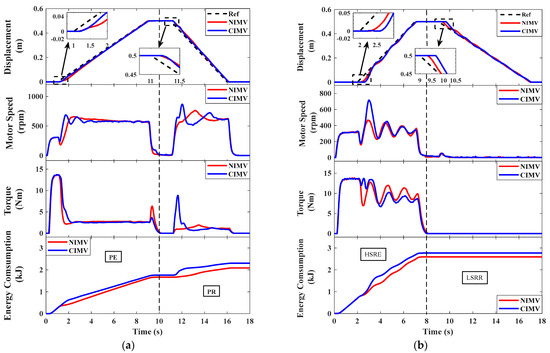
Figure 7.
Comparison of the operation between the NIMV and CIMV systems in both cycles. (a) Cycle 1; (b) Cycle 2.
The final model used in this experiment is the LSRR mode, from 24 to 35 s. In this regeneration mode, only the valve is controlled while the pump is turned off. However, the difference between the VFPB method and this mode, and the other 3 modes, is that the Kbt and Kab valves are controlled together. In this case, the Kbt valve has the function of a check valve, which helps the flow rate from the bore chamber go into the rod chamber. If the Kbt valve is opened fully, the oil from the bore chamber will flow directly into the tank. Therefore, if the required oil for the rod chamber is insufficient, it risks the creation of air bubbles in the oil when the rod chamber draws oil. In addition, the cylinder speed is controlled by the Kab valve; hence, the cylinder moves down stably and follows the design trajectory.
4.2. Comparison with CIMV
We conducted an experiment to compare the energy consumption of the NIMV system to that of the CIMV system in order to assess its effectiveness. Two cycles were chosen, with Cycle 1 including two modes: PE and PR (see Figure 7a) and the other including the HSRE and LSRR modes (see Figure 7b). The energy consumption and energy savings of each mode are recorded and shown in Table 3.

Table 3.
The energy consumption of the experiment model.
Figure 7a describes the energy consumption between the NIMV and CIMV in cycle 1. The energy consumption of the NIMV was lower than that of the CIMV, i.e., the energy-saving on the PE mode was 4% and that of PR was 22%. The reason is that the returned oil to the tank of the CIMV system needed to maintain a higher pressure than the setting pressure in the check valve. This leads to more energy being required from the pump. Therefore, from 1 to 2 s, the speed and torque of the CIMV system were higher because during this time the pump needed to supply a greater flow rate to reduce the delay response of the cylinder. Similarly, from 11 to 12 s in the PR mode, the cylinder moved down unimpeded in the NIMV system (does not have a check valve), so the torque from the motor was very low. Thus, this system has better energy savings than the CIMV system. However, with more used energy, the CIMV system can achieve a better tracking performance in the early stage. The comparison is evaluated based on the displacement tracking error, as shown in Figure 8a. Although the displacement error of the NIMV is higher in the early stage (from 1 to 5.5 s), it is closer to the target position after that (similar to the PR mode).
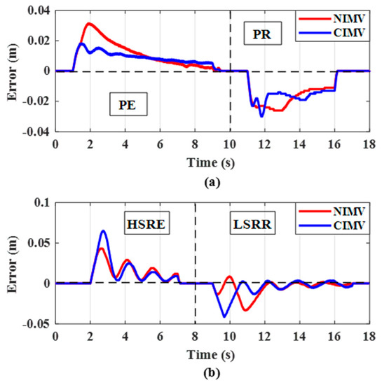
Figure 8.
Comparison of the displacement errors in the NIMV and CIMV systems. (a) Cycle 1; (b) Cycle 2.
The results of Cycle 2 are displayed in Figure 7b, with the LSRR mode consuming nearly no energy on both systems. The energy is consumed mainly in the HSRE mode, which is better in the NIMV system because, in this mode, losses mainly occur at the EHPV. In the NIMV system, the oil from the pump flows through the Ksa valve combining with the returned oil from the rod chamber and flows to the bore chamber. In contrast, in the CIMV system, the oil from the pump combines with the returned oil from the rod chamber and flows through the Ksa valve after that. Therefore, losses at the Ksa valve of the CIMV system are higher than those of the NIMV system. In addition, in the LSRR mode, the check valve of the CIMV system causes the delayed response time of the cylinder, thus it takes a long time to move the cylinder in the starting cycle. From the cylinder displacement results, Figure 7b shows that the cylinder in the NIMV system has a better tracking performance and a faster response time. In addition, the displacement tracking error from the NIMV system is lower than that of the CIMV system, as shown in Figure 8b. Therefore, this proves that the proposed system, not only focuses on minimizing the factors that cause losses in the IMV system, but also achieves a good working performance.
5. Conclusions
In this paper, a new IMV configuration that could regenerate gravitational potential energy was developed for a boom system. The proposed structure included three EHPVs and one directional valve that could ensure similar working modes as the CIMV system. In addition, a control strategy was developed based on the velocity feed-forward and position feedback method to improve the stability and safety of the proposed system. A real test bench, based on laboratory conditions, was built to evaluate the effectiveness of the NIMV system in detail. Then, the NIMV system was compared with the CIMV system in terms of the working performance and energy-saving potential. The results showed that the NIMV system outperformed the CIMV system in terms of the following characteristics:
- The energy savings of the NIMV system was higher than the CIMV system by approximately 4% in the PE mode, 22% in the PR mode and 6.5% in the HSRE mode. The proposed system removed the use of a check valve, which is the main factor that caused energy loss in the CIMV system. Moreover, the throttling loss was reduced by the valves, which were logically connected, and are shown in the HSRE mode.
- In the proposed configuration, the cost of the system was significantly reduced by reducing one EHPV and a check valve, while ensuring the stability of the IMV system.
- Both systems applied a simple controller and achieved a high tracking performance. However, by eliminating the factors that cause losses in the system, the NIMV system could work with a higher precision and stability. Especially, the displacement tracking error of the cylinder in the NIVM system was about 0.043 m in the HSRE mode and about 0.034 m in the LSRR mode, while in the CIMV system it was around 0.065 m and 0.04 m, respectively.
However, the test bench still exhibits some limitations. First, these studies only focused on the boom system, so the LSRR mode was omitted in the experiments. Second, the PE and HSRE modes were differentiated based on two factors, the velocity and load force. However, the load force in this test bench was a fixed value. Thus, the switching mode must be designed based on the speed to determine the mode of operation.
Generally, a NIMV, with its proper logic control, has a strong ability to be applied in practical applications. In future research, we will improve the proposed configuration, apply mode switching for the system, and integrate the NIMV system into a real excavator. With the energy-saving potential and a good working performance, the proposed NIMV will be a trending research direction in the future.
Author Contributions
K.-K.A. was the supervisor providing funding and administrating the project, and he reviewed and edited the manuscript. T.-H.N. carried out the investigation, methodology, analysis, and validation and wrote the original manuscript. T.-C.D. checked the manuscript and supported the model for research. All authors have read and agreed to the published version of the manuscript.
Funding
This research was supported by Basic Science Program through the National Research Foundation of Korea (NRF) funded by the Ministry of Science and ICT, South Korea (NRF 2020R1A2B5B03001480) and this work was supported by "Regional Innovation Strategy (RIS)" through the National Research Foundation of Korea(NRF) funded by the Ministry of Education(MOE) (2021RIS-003).
Institutional Review Board Statement
Not applicable.
Informed Consent Statement
Not applicable.
Data Availability Statement
Thank you very much. We have understood and agreed to the policies of MDPI.
Conflicts of Interest
The authors declare no conflict of interest.
References
- Jud, D.; Kerscher, S.; Wermelinger, M.; Jelavic, E.; Egli, P.; Leemann, P.; Hottiger, G.; Hutter, M. HEAP—The autonomous walking excavator. Autom. Constr. 2021, 129, 103783. [Google Scholar] [CrossRef]
- Tyni, P. Development of an Earthmoving Machinery Autonomous Excavator Development Platform. In Proceedings of the 36th International Symposium on Automation and Robotics in Construction (ISARC), Banff, AB, Canada, 21–24 May 2019. [Google Scholar]
- Shen, W.; Jiang, J.; Su, X.; Reza Karimi, H. Control strategy analysis of the hydraulic hybrid excavator. J. Frankl. Inst. 2015, 352, 541–561. [Google Scholar] [CrossRef]
- Vukovic, M.; Leifeld, R.; Murrenhoff, H. Reducing Fuel Consumption in Hydraulic Excavators—A Comprehensive Analysis. Energies 2017, 10, 687. [Google Scholar] [CrossRef] [Green Version]
- Yoon, J.I.; Truong, D.Q.; Ahn, K.K. A generation step for an electric excavator with a control strategy and verifications of energy consumption. Int. J. Precis. Eng. Manuf. 2013, 14, 755–766. [Google Scholar] [CrossRef]
- Do, T.C.; Dang, T.D.; Dinh, T.Q.; Ahn, K.K. Developments in energy regeneration technologies for hydraulic excavators: A review. Renew. Sustain. Energy Rev. 2021, 145, 111076. [Google Scholar] [CrossRef]
- Wang, T.; Wang, Q.; Lin, T. Improvement of boom control performance for hybrid hydraulic excavator with potential energy recovery. Autom. Constr. 2013, 30, 161–169. [Google Scholar] [CrossRef]
- Yu, Y.-X.; Ahn, K.K. Energy Regeneration and Reuse of Excavator Swing System with Hydraulic Accumulator. Int. J. Precis. Eng. Manuf.-Green Technol. 2020, 7, 859–873. [Google Scholar] [CrossRef]
- Yu, Y.-X.; Ahn, K.K. Improvement of Energy Regeneration for Hydraulic Excavator Swing System. Int. J. Precis. Eng. Manuf. -Green Technol. 2020, 7, 53–67. [Google Scholar] [CrossRef]
- Mirzaliev, S. A Review of Energy Saving Techniques in Mobile Hydraulic Machines. Preprints 2018, 2018100193. [Google Scholar] [CrossRef]
- Lin, T.; Chen, Q.; Ren, H.; Huang, W.; Chen, Q.; Fu, S. Review of boom potential energy regeneration technology for hydraulic construction machinery. Renew. Sustain. Energy Rev. 2017, 79, 358–371. [Google Scholar] [CrossRef]
- Liu, J.; Jiao, Z.; Xian, F.; Liu, W. Energy recovery and utilization system of excavator boom based on flow regeneration and balance theory. J. Braz. Soc. Mech. Sci. Eng. 2019, 42, 35. [Google Scholar] [CrossRef]
- Ding, R.; Zhang, J.; Xu, B. Advanced Energy Management of a Novel Independent Metering Meter-Out Control System: A Case Study of an Excavator. IEEE Access 2018, 6, 45782–45795. [Google Scholar] [CrossRef]
- Do, T.C.; Nguyen, D.G.; Dang, T.D.; Ahn, K.K. A Boom Energy Regeneration System of Hybrid Hydraulic Excavator Using Energy Conversion Components. Actuators 2021, 10, 1. [Google Scholar] [CrossRef]
- Yu, Y.; Do, T.C.; Park, Y.; Ahn, K.K. Energy saving of hybrid hydraulic excavator with innovative powertrain. Energy Convers. Manag. 2021, 244, 114447. [Google Scholar] [CrossRef]
- Ge, L.; Quan, L.; Li, Y.; Zhang, X.; Yang, J. A novel hydraulic excavator boom driving system with high efficiency and potential energy regeneration capability. Energy Convers. Manag. 2018, 166, 308–317. [Google Scholar] [CrossRef]
- Nguyen Thanh, H.; Do Tri, C.; Ahn Kyoung, K. Independent Metering Valve: A Review of Advances in Hydraulic Machinery. J. Drive Control 2020, 17, 54–71. [Google Scholar]
- Abuowda, K.; Okhotnikov, I.; Noroozi, S.; Godfrey, P.; Dupac, M. A review of electrohydraulic independent metering technology. ISA Trans. 2020, 98, 364–381. [Google Scholar] [CrossRef]
- Weber, J. Independent metering systems. Int. J. Hydromechatronics 2018, 1, 91. [Google Scholar] [CrossRef]
- Liu, K.; Gao, Y.; Tu, Z.; Lin, P. Energy-saving analysis of the independent metering system with pressure compensation for excavator’s manipulator. J. Syst. Control Eng. 2016, 230, 905–920. [Google Scholar] [CrossRef]
- Shenouda, A.; Book, W. Energy Saving Analysis Using a Four-Valve Independent Metering Configuration Controlling a Hydraulic Cylinder. In SAE Technical Paper; SAE International: Warrendale, PA, USA, 2005. [Google Scholar]
- Liu, K.; Gao, Y.; Tu, Z. Energy saving potential of load sensing system with hydro-mechanical pressure compensation and independent metering. Int. J. Fluid Power 2016, 17, 173–186. [Google Scholar] [CrossRef]
- Lyu, L.; Chen, Z.; Yao, B. Development of Pump and Valves Combined Hydraulic System for Both High Tracking Precision and High Energy Efficiency. IEEE Trans. Ind. Electron. 2019, 66, 7189–7198. [Google Scholar] [CrossRef]
- Lyu, L.; Chen, Z.; Yao, B. Energy Saving Motion Control of Independent Metering Valves and Pump Combined Hydraulic System. IEEE/ASME Trans. Mechatron. 2019, 24, 1909–1920. [Google Scholar] [CrossRef]
- Abuowda, K.; Noroozi, S.; Dupac, M.; Godfrey, P. Algorithm Design for the Novel Mechatronics Electro-Hydraulic Driving System: Micro-Independent Metering. In Proceedings of the 2019 IEEE International Conference on Mechatronics (ICM), Ilmenau, Germany, 18–20 March 2019; Volume 1, pp. 7–12. [Google Scholar]
- Abuowda, K.; Dupac, M.; Noroozi, S.; Godfrey, P. Mathematical-based control method and performance analysis of a novel hydromechatronics driving system micro-independent metering. Math. Methods Appl. Sci. 2020. [Google Scholar] [CrossRef]
- Tabor, K.A. Optimal Velocity Control and Cavitation Prevention of a Hydraulic Actuator Using Four Valve Independent Metering. In SAE Technical Paper; SAE International: Warrendale, PA, USA, 2005. [Google Scholar]
- Choi, K.; Seo, J.; Nam, Y.; Kim, K.U. Energy-saving in excavators with application of independent metering valve. J. Mech. Sci. Technol. 2015, 29, 387–395. [Google Scholar] [CrossRef]
- Ding, R.; Xu, B.; Zhang, J.; Cheng, M. Self-tuning pressure-feedback control by pole placement for vibration reduction of excavator with independent metering fluid power system. Mech. Syst. Signal Process. 2017, 92, 86–106. [Google Scholar] [CrossRef]
- Lyu, L.; Chen, Z.; Yao, B. High Precision Energy Saving Motion Control of Hydraulic Cylinder Based on Integration of Valves and Pump. In Proceedings of the BATH/ASME 2018 Symposium on Fluid Power and Motion Control, Bath, UK, 12–14 September 2018; 2018; p. V001T01A019. [Google Scholar]
- Helian, B.; Chen, Z.; Yao, B. Precision Motion Control of a Servomotor-Pump Direct-Drive Electrohydraulic System With a Nonlinear Pump Flow Mapping. IEEE Trans. Ind. Electron. 2020, 67, 8638–8648. [Google Scholar] [CrossRef]
- Ding, R.; Cheng, M.; Zheng, S.; Xu, B. Sensor-Fault-Tolerant Operation for the Independent Metering Control System. IEEE/ASME Trans. Mechatron. 2020, 26, 2558–2569. [Google Scholar] [CrossRef]
- Xu, B.; Ding, R.; Zhang, J.; Cheng, M.; Sun, T. Pump/valves coordinate control of the independent metering system for mobile machinery. Autom. Constr. 2015, 57, 98–111. [Google Scholar] [CrossRef]
- Ding, R.; Xu, B.; Zhang, J.; Cheng, M. Bumpless mode switch of independent metering fluid power system for mobile machinery. Autom. Constr. 2016, 68, 52–64. [Google Scholar] [CrossRef]
- Shi, J.; Quan, L.; Zhang, X.; Xiong, X. Electro-hydraulic velocity and position control based on independent metering valve control in mobile construction equipment. Autom. Constr. 2018, 94, 73–84. [Google Scholar] [CrossRef]
- Zhang, X.; Qiao, S.; Quan, L.; Ge, L. Velocity and Position Hybrid Control for Excavator Boom Based on Independent Metering System. IEEE Access 2019, 7, 71999–72011. [Google Scholar] [CrossRef]
- Ahamad, M.; Dinh, Q.-T.; Nahian, S.A.; Ahn, K.-K. Development of a New Generation of Independent Metering Valve Circuit for Hydraulic Boom Cylinder Control. Int. J. Autom. Technol. 2015, 9, 143–152. [Google Scholar] [CrossRef]
Publisher’s Note: MDPI stays neutral with regard to jurisdictional claims in published maps and institutional affiliations. |
© 2022 by the authors. Licensee MDPI, Basel, Switzerland. This article is an open access article distributed under the terms and conditions of the Creative Commons Attribution (CC BY) license (https://creativecommons.org/licenses/by/4.0/).