
Design of a Damping Controller Using a Metaheuristic Algorithm for Angle Stability Improvement of an MIB System

 and
and 
Abstract
:1. Introduction
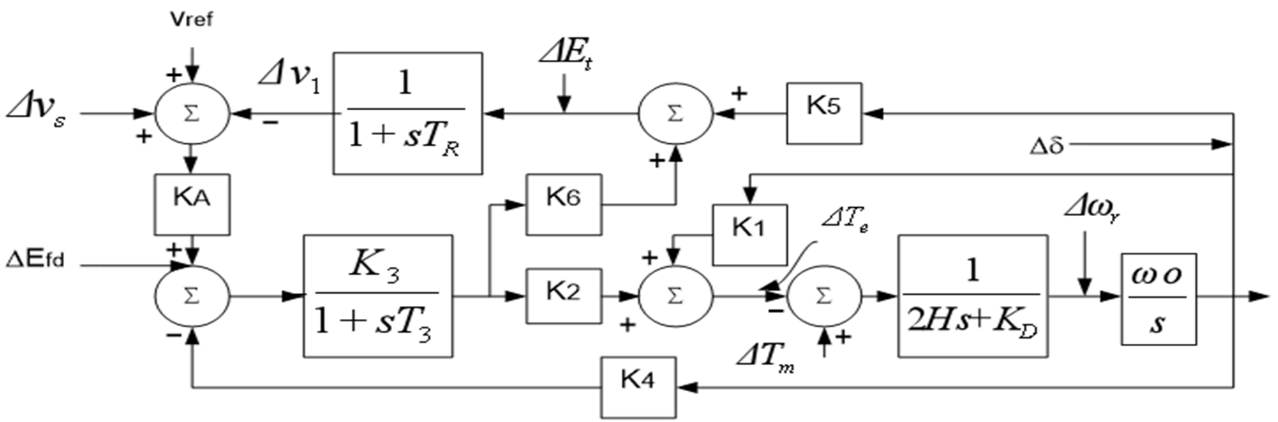
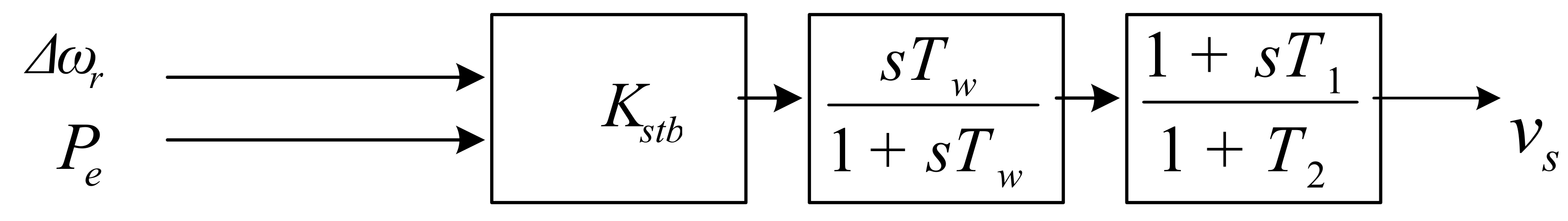
2. Modelling of SMIB with AVR and PSS Damping Controllers
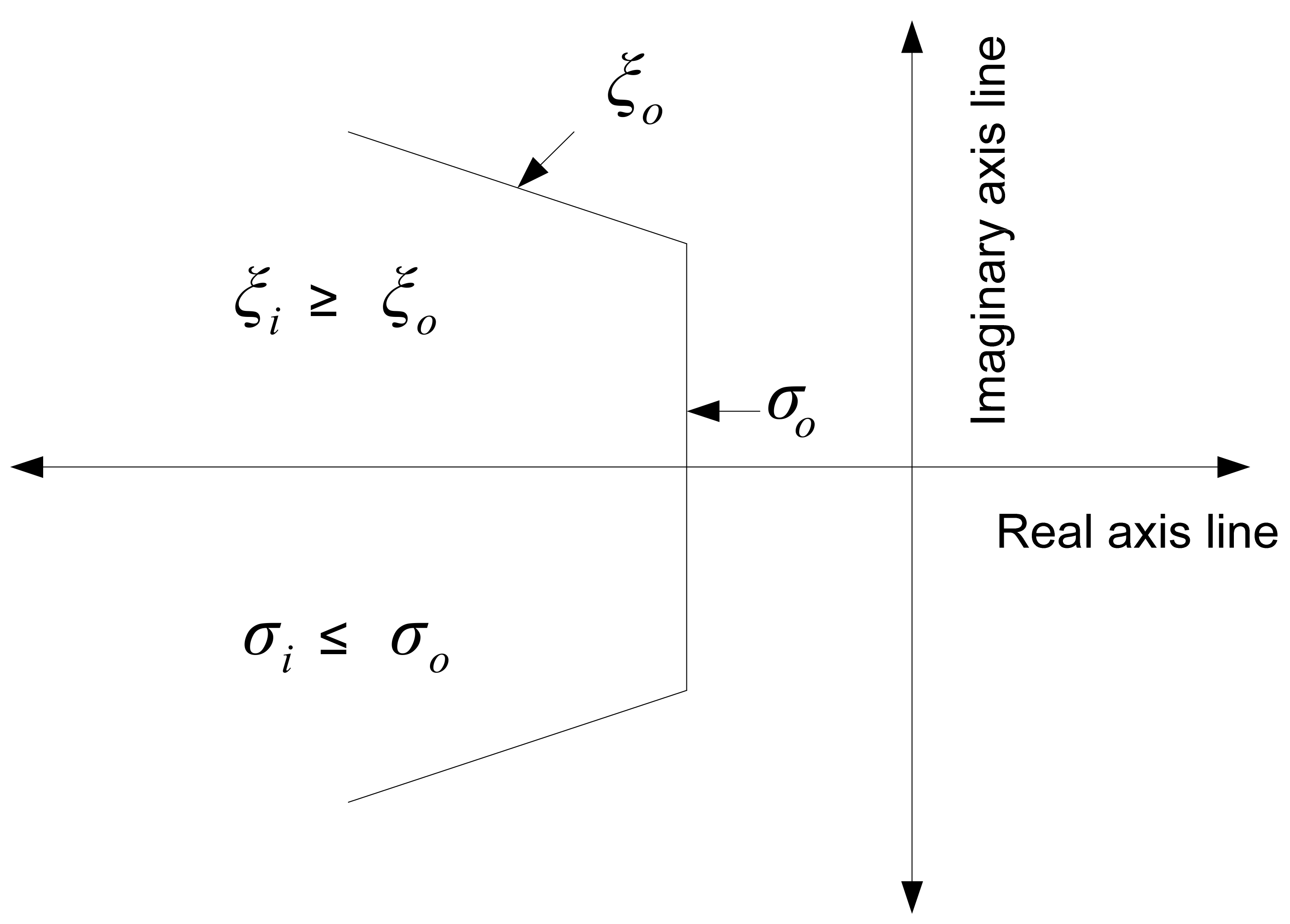
3. Objective Function to Tune the PSS Parameters
- , min ≤ ≤ , max,
- , min ≤ ≤ , max,
- , min ≤ ≤ , max.
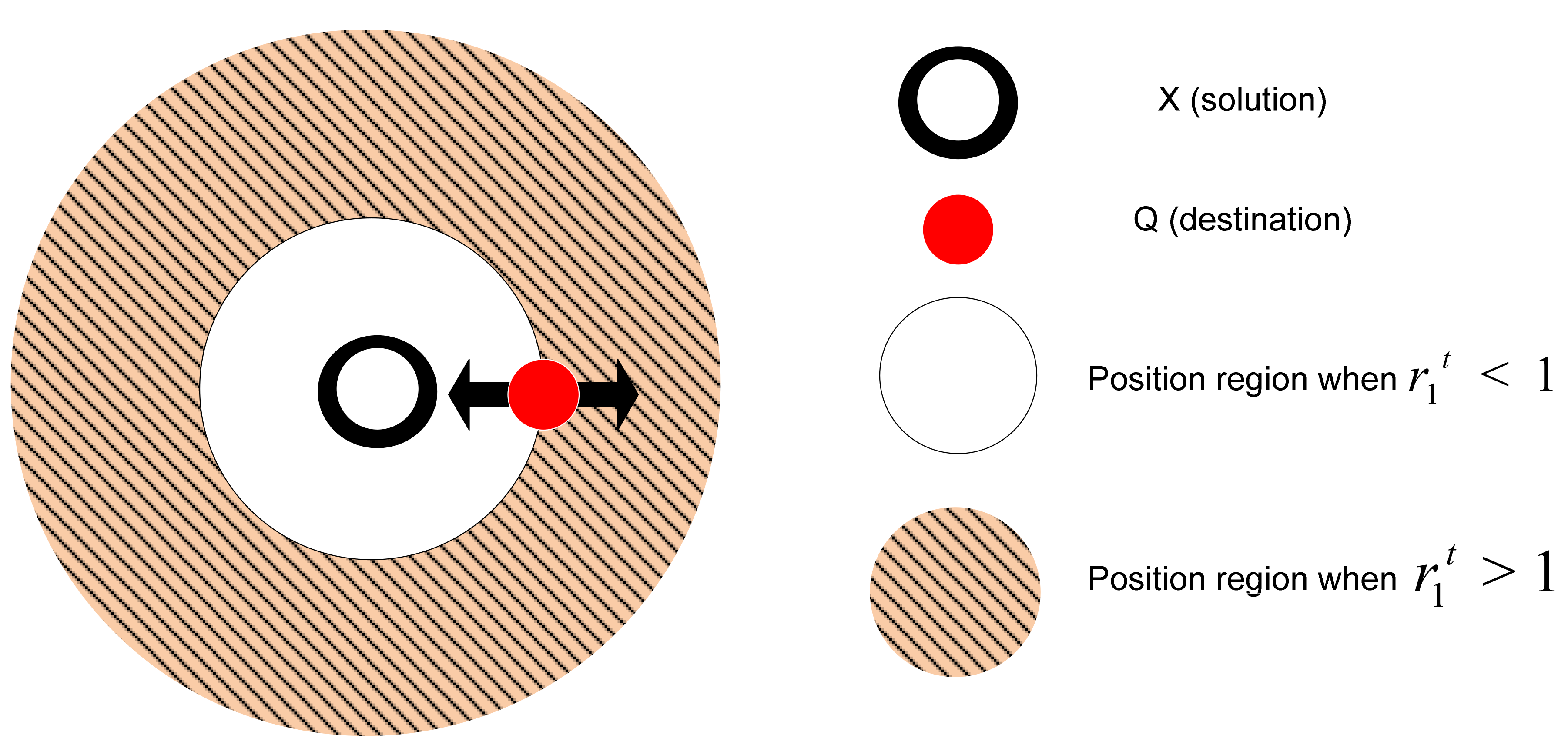
4. SCA
5. Moth Flame Optimisation (MFO) Algorithm
6. Evolutionary Programming Algorithm
7. Advantages of SCA over MFO and EP
8. Results and Discussion

| Modules | Parameters |
|---|---|
| Generator | H = 3.50, = 1.0 < 36°, ′ = 0.30, = 0.0030, = 1.810, = 1.760, = 8, = 0.84910, = 0.84910. |
| Power line | = 0.650, = 0.160, = 0.0 |
| AVR with PSS-LL controller | = 0.020, = 1.40, = 200.0 |
9. Conclusions
Author Contributions
Funding
Institutional Review Board Statement
Informed Consent Statement
Data Availability Statement
Conflicts of Interest
References
- Kundur, P. Power System Stability and Control, 3rd ed.; McGraw-Hill Education: New York, NY, USA, 1994; pp. 17–817. [Google Scholar]
- Mchowski, J.; Bialek, J.W.; Bumby, J.R. Power System Dynamics: Stability and Control, 2nd ed.; John Wiley & Sons Ltd.: Chichester, UK, 1997; pp. 169–261. [Google Scholar]
- Anderson, P.M.; Fouad, A.A. Power System Control and Stability, 2nd ed.; Wiley-IEEE Press: Danvers, MA, USA, 2002; pp. 13–148. [Google Scholar]
- Hannan, M.A.; Islam, N.N.; Mohamed, A.; Lipu, M.S.H.; Ker, P.J.; Rashid, M.M.; Shareef, H. Artificial Intelligent Based Damping Controller Optimization for the Multi-Machine Power System: A Review. IEEE Access 2018, 6, 39574–39594. [Google Scholar] [CrossRef]
- Kamari, N.A.M.; Musirin, I.; Ibrahim, A.A. Swarm Intelligence Approach for Angle Stability Improvement of PSS and SVC-Based SMIB. J. Electr. Eng. Technol. 2020, 15, 1001–1014. [Google Scholar] [CrossRef]
- Wang, B.; Sun, K. Formulation and Characterization of Power System Electromechanical Oscillations. IEEE Trans. Power Syst. 2016, 31, 5082–5093. [Google Scholar] [CrossRef]
- Kumar, A. Power System Stabilizers Design for Multimachine Power System Using Local Measurements. IEEE Trans. Power Syst. 2016, 31, 2163–2171. [Google Scholar] [CrossRef]
- Jalayer, R.; Ooi, B.-T. Co-Ordinated PSS Tuning of Large Power Systems by Combing Transfer Function-Eigenfunction Analysis (TFEA), Optimization, and Eigenvalue Sensitivity. IEEE Trans. Power Syst. 2014, 29, 2672–2680. [Google Scholar] [CrossRef]
- Bian, X.Y.; Geng, Y.; Lo, K.L.; Fu, Y.; Zahou, Q.B. Coordination of PSSs and SVC Damping Controller to Improve Probabilistic Small-Signal Stability of Power System with Wind Farm Integration. IEEE Trans. Power Syst. 2016, 31, 2371–2382. [Google Scholar] [CrossRef] [Green Version]
- Guesmi, T.; Alshammari, B.M.; Almalaq, Y.; Alateeq, A.; Alqunun, K. New Coordinated Tuning of SVC and PSSs in Multimachine Power System Using Coyote Optimization Algorithm. Sustainability 2021, 13, 3131. [Google Scholar] [CrossRef]
- Li, C.; Deng, J.; Zhang, X.-P. Coordinated Design and Application of Robust Damping Controllers for Shunt FACTS Devices to Enhance Small-single Stability of Large-scale Power Systems. J. Power Energy Syst. 2017, 3, 399–407. [Google Scholar]
- Jiang, S.; Gole, A.M.; Annakkage, U.D.; Jacobson, D.A. Damping Performance Analysis of IPFC and UPFC Controllers using Validated Small-Single Models. IEEE Trans. Power Deliv. 2011, 26, 446–454. [Google Scholar] [CrossRef]
- Parastvand, H.; Bass, O.; Masoum, M.A.S.; Chapman, A.; Lachowicz, L. Cyber-Security Constrained Placement of FACTS Devices in Power Networks from a Novel Topological Perspective. IEEE Access 2020, 8, 108201–108215. [Google Scholar] [CrossRef]
- Zhou, L.; Swain, A.; Ukil, A. Reinforcement Learning Controllers for Enhancement of Low Voltage Ride Through Capability in Hybrid Power Systems. IEEE Trans. Ind. Inform. 2020, 16, 5023–5031. [Google Scholar] [CrossRef]
- Guangzheng, Y.; Lin, T.; Zhang, J.; Tian, Y.; Yang, X. Coordination of PSS and FACTS Damping Controllers to Improve Small Signal Stability of Large-Scale Power System. J. Power Energy Syst. 2019, 5, 507–514. [Google Scholar]
- Zuo, J.; Li, Y.; Shi, D.; Duan, X. Simultaneous Robust Coordinated Damping Control of Power System Stabilizers (PSSs), Static Var Compensator (SVC) and Doubly-Fed Induction Generator Power Oscillation Dampers (DFIG PODs) in Multimachine Power Systems. Energies 2017, 10, 565. [Google Scholar] [CrossRef] [Green Version]
- Baek, S.-M.; Park, J.-W. Nonlinear Parameter Optimization of FACTS Controller via Real-Time Digital Simulator. IEEE Trans. Ind. Appl. 2013, 49, 2271–2278. [Google Scholar] [CrossRef]
- Al-Ismail, F.S.; Hassan, M.A.; Abido, M.A. RTDS Implementation of STATCOM-Based Power System Stabilizers. Can. J. Electr. Comput. Eng. 2014, 37, 48–56. [Google Scholar] [CrossRef]
- Pandey, R.K.; Gupta, D.K. Integrated Multi-stage LQR Power Oscillation Damping FACTS Controller. JPES 2018, 4, 83–92. [Google Scholar] [CrossRef]
- Jiang, P.; Fan, Z.; Feng, S.; Wu, X.; Cai, H.; Xie, Z. Mitigation of power forced oscillations based on unified power flow controller. J. Mod. Power Syst. Clean Energy 2019, 7, 99–112. [Google Scholar] [CrossRef] [Green Version]
- Quan, W.; Su, Q. Improved Adaptive Backstepping Approach on STATCOM Controller of Nonlinear Power System. IEEE Access 2019, 7, 139109–139117. [Google Scholar] [CrossRef]
- Asgharian, A.; Tavakoli, S.A. A Systematic Approach to Performance Weights Selection in Design of Robust H PSS using Genetic Algorithms. IEEE Trans. Energy Convers. 1996, 11, 111–117. [Google Scholar] [CrossRef]
- Kahouli, A.; Guesmi, T.; Abdallah, H.H.; Quali, A. A Genetic Algorithm PSS and AVR Controller for Electrical Power System Stability. In Proceedings of the 6th International Multi-Conference on Systems, Signals and Devices, Djerba, Tunisia, 23–26 March 2009. [Google Scholar]
- Hassan, L.H.; Moghavvemi, M.; Almurib, H.A.F.; Muttaqi, K.M. A Coordinated Design of PSSs and UPFC-based Stabilizer using Genetic Algorithm. IEEE Trans. Ind. Appl. 2014, 50, 2957–2966. [Google Scholar] [CrossRef]
- Gupta, N.; Agarwal, T. Design of Optimal Power System Stabilizer using GA and PSO: A Comparative Study. In Proceedings of the IEEE International Conference on Recent Advances and Innovations in Engineering, Jaipur, India, 23–25 December 2016. [Google Scholar]
- Verdejo, H.; Pino, V.; Kliemann, W.; Becker, C.; Delpiano, J. Implementation of Particle Swarm Optimization (PSO) Algorithm for Tuning of Power System Stabilizers in Multimachine Electric Power Systems. Energies 2020, 13, 2093. [Google Scholar] [CrossRef] [Green Version]
- Dasu, B.; Kumar, M.S.; Rao, R.S. Design of robust modified power system stabilizer for dynamic stability improvement using Particle Swarm Optimization technique. Ain Shams Eng. J. 2019, 10, 769–783. [Google Scholar] [CrossRef]
- Islam, N.N.; Hannan, M.A.; Shareef, H.; Mohamed, A. Power System Stabilizer Design using BAT Optimization algorithm in Multimachine Power System. In Proceedings of the IEEE Student Conference on Research and Development, Putrajaya, Malaysia, 16–17 December 2013. [Google Scholar]
- Mehta, P.; Bhatt, P.; Pandya, V. Optimized coordinated control of frequency and voltage for distributed generating system using Cuckoo Search Algorithm. Ain Shams Eng. J. 2018, 9, 1855–1864. [Google Scholar] [CrossRef]
- Sheshnarayan; Verma, B.; Padhy, P.K. Design PID Controller based PSS using Cuckoo Search Optimization Technique. In Proceedings of the 4th International Conference on Recent Trend on Electronics, Information, Communication & Technology, Bengaluru, India, 17–18 May 2019. [Google Scholar]
- Chaib, L.; Choucha, A.; Arif, S. Optimal design and tuning of novel fractional order PID power system stabilizer using a new metaheuristic Bat algorithm. Ain Shams Eng. J. 2017, 8, 113–125. [Google Scholar] [CrossRef] [Green Version]
- Islam, N.N.; Hannan, M.A.; Shareef, H.; Mohamed, A. SVC Damping Controller Design Based on Firefly Optimization Algorithm in Multi Machine Power System. In Proceedings of the IEEE Conference on Clean Energy and Technology, Langkawi, Malaysia, 18–20 November 2013. [Google Scholar]
- Verdejo, H.; Torres, R.; Pino, V.; Kliemann, W.; Becker, C.; Delpiano, J. Tuning of Controllers in Power Systems Using a Heuristic-Stochastic Approach. Energies 2019, 12, 2325. [Google Scholar] [CrossRef] [Green Version]
- Khawaja, A.W.; Kamari, N.A.M.; Zainuri, M.A.A.M. Design of a Damping Controller Using the SCA Optimization Technique for the Improvement of Small Signal Stability of a Single Machine Connected to an Infinite Bus System. Energies 2021, 14, 2996. [Google Scholar] [CrossRef]
- Kamari, N.A.M.; Musirin, I.; Hamid, Z.A.; Rahim, M.N.A. EP-Based Optimisation for Estimating Synchronising and Damping Torque Coefficients. Aust. J. Basic Appl. Sci. 2010, 4, 3741–3754. [Google Scholar]
- Mirjalili, S. SCA: A Sine Cosine Algorithm for Solving optimization problems. Knowl.-Based Syst. 2016, 96, 120–133. [Google Scholar] [CrossRef]
- Mirjalili, S. Moth-flame optimization algorithm: A novel nature-inspired heuristic paradigm. Knowl.-Based Syst. 2015, 89, 228–249. [Google Scholar] [CrossRef]


| SCA Pseudocode |
|---|
| Initialise the population for i = 1:size(X,1) Objective values(1,i) = fobj(X(i,:)); if i == 1 Destination position = X(i,:); Destination fitness = Objective values(1,i); elseif Objective values(1,i) < Destination fitness Destination position = X(i,:); Destination fitness = Objective values(1,i); end if All objective values(1,i) = Objective values(1,i); end for whilst iteration maximum iterations do r1 = a − t*((a)/max_iteration) calculate the number using Equation () for i = 1 to n do for j = 1 to n do r2 = 2 * pi * rand() r3 = 2 * (rand()) r4 = rand() Update r2, r3 and r4 for Equation () if r4 < 0.5 % Equatoin () X(i,j) = X(i,j) + (r1 * sin(r2) * abs(r3 * Destination position(j) − X(i,j))); else % Equation () X(i,j) = X(i,j) + (r1 * cos(r2) * abs(r3 * Destination position(j) − X(i,j))); if Objective values(1,i) < Destination fitness Destination position = X(i,:); Destination fitness = Objective values(1,i); end if end if end for end for Convergence curve(t) = Destination fitness; if mod(t,50) == 0 display([‘At iteration’, num2str(t), ‘the optimum is’, num2str(Destination fitness)]); end show the best amongst solutions end whilst |
| MFO Algorithm Pseudocode |
|---|
| Randomly initialise the population for the moth flame by moth position Ni for i = 1 to n do calculate fitness function fi end for whilst iteration maximum iterations do reform the location of Ni calculate the number of flames using Equation () weigh up fi, the fitness function fi if iteration == 1 next F = rank(N) and OF = rank(ON) else F= rank(Nt − 1, Nt) and OF = rank(ONt − 1, ONt) end if for i = 1 to n do for j = 1 to n do reform the values of t and r determine the value of G using Equation () update N(i,j) to its moth using Equation () end for end for end whilst show the best amongst solutions P |
| Evolutionary Programming Algorithm Pseudocode |
|---|
| Initialise the population for i = 1 to n do //parents/// for j = 1 to K populations do describe (i) and J((i)) end for ///offspring/// for j = 1 to N populations do (i) = α × ( − ) × Calculate (i) end for merge both offspring and parents sort x(i) in descending arrangement of J(x(i)) pick best one-half x(i) value, the same as brand-new (i) if | − | < then end if i = i + 1 end for |
| Loading Conditions | Active Power, P (p. u) | Reactive Power, Q (p. u) |
|---|---|---|
| 1 | P = 0.9 | Q = 0.2 |
| 2 | P = 0.9 | Q = 0.3 |
| 3 | P = 0.9 | Q = 0.4 |
| 4 | P = 0.5 | Q = 0.5 |
| 5 | P = 0.2 | Q = 0.7 |
| Optimisation Techniques | Parameters Range | Optimised PSS Parameter Range Limit |
|---|---|---|
| SCA | = 2 to 0, = 0 to 2π, = 0 to 2, = 0 to 1 | = 0.001, = 0.2 = 0.001, = 0.1 = 9, = 200 |
| MFO | d = 0.00025, t = −1 to 1 | |
| EP | β = 0.1 |
| Loading Condition 1 | ||||
|---|---|---|---|---|
| Methods | PSS−SCA | PSS-MFO | PSS-EP | PSS-U |
| PSS optimised parameters | = 0.03224 = 0.00179 = 31.75167 | = 0.03739 = 0.0050 = 31.52837 | = 0.06511 = 0.00142 = 35.44624 | = 0.1 = 0.04 = 9 |
| Objective function | 0.7420 | 0.7240 | 0.6770 | 0.1267 |
| Number of iterations | 46 | 103 | 19 | NA |
| Loading Condition 2 | ||||
|---|---|---|---|---|
| Methods | PSS-SCA | PSS-MFO | PSS-EP | PSS-U |
| PSS optimised parameters | = 0.02499 = 0.00150 = 32.96348 | = 0.02888 = 0.00413 = 32.83729 | = 0.06651 = 0.00152 = 37.41522 | = 0.1 = 0.04 = 9 |
| Objective function | 0.7340 | 0.7227 | 0.6609 | 0.1209 |
| Number of iterations | 44 | 96 | 23 | NA |
| Loading Condition 3 | ||||
|---|---|---|---|---|
| Methods | PSS-SCA | PSS-MFO | PSS-EP | PSS-U |
| PSS optimised parameters | = 0.01780 = 0.001403 = 33.9990 | = 0.02630 = 0.01103 = 33.27788 | = 0.06711 = 0.00154 = 38.34156 | = 0.1 = 0.04 = 9 |
| Objective function | 0.7300 | 0.7121 | 0.6337 | 0.1145 |
| Number of iterations | 34 | 102 | 23 | NA |
| Loading Condition 4 | ||||
|---|---|---|---|---|
| Methods | PSS-SCA | PSS-MFO | PSS-EP | PSS-U |
| PSS optimised parameters | = 0.04316 = 0.05061 = 53.25110 | = 0.05327 = 0.06027 = 54.32393 | = 0.04259 = 0.04422 = 49.64898 | = 0.1 = 0.04 = 9 |
| Objective function | 0.7559 | 0.7407 | 0.6764 | 0.1144 |
| Number of iterations | 42 | 94 | 20 | NA |
| Loading Condition 5 | ||||
|---|---|---|---|---|
| Methods | PSS-SCA | PSS-MFO | PSS-EP | PSS-U |
| PSS optimised parameters | = 0.02396 = 0.04134 = 140.61181 | = 0.03471 = 0.04984 = 147.61060 | = 0.02888 = 0.04339 = 154.93417 | = 0.1 = 0.04 = 9 |
| Objective function | 0.8299 | 0.7839 | 0.6384 | 0.0641 |
| Number of iterations | 38 | 99 | 13 | NA |
Publisher’s Note: MDPI stays neutral with regard to jurisdictional claims in published maps and institutional affiliations. |
© 2022 by the authors. Licensee MDPI, Basel, Switzerland. This article is an open access article distributed under the terms and conditions of the Creative Commons Attribution (CC BY) license (https://creativecommons.org/licenses/by/4.0/).
Share and Cite
Khawaja, A.W.; Kamari, N.A.M.; Zainuri, M.A.A.M. Design of a Damping Controller Using a Metaheuristic Algorithm for Angle Stability Improvement of an MIB System. Appl. Sci. 2022, 12, 589. https://doi.org/10.3390/app12020589
Khawaja AW, Kamari NAM, Zainuri MAAM. Design of a Damping Controller Using a Metaheuristic Algorithm for Angle Stability Improvement of an MIB System. Applied Sciences. 2022; 12(2):589. https://doi.org/10.3390/app12020589
Chicago/Turabian StyleKhawaja, Abdul Waheed, Nor Azwan Mohamed Kamari, and Muhammad Ammirrul Atiqi Mohd Zainuri. 2022. "Design of a Damping Controller Using a Metaheuristic Algorithm for Angle Stability Improvement of an MIB System" Applied Sciences 12, no. 2: 589. https://doi.org/10.3390/app12020589
APA StyleKhawaja, A. W., Kamari, N. A. M., & Zainuri, M. A. A. M. (2022). Design of a Damping Controller Using a Metaheuristic Algorithm for Angle Stability Improvement of an MIB System. Applied Sciences, 12(2), 589. https://doi.org/10.3390/app12020589