Abstract
The hypervelocity impact of space debris causes damage or destruction to spacecraft. The continuous damage caused by space debris creates greater requirements for protective materials. Wave-impedance gradient-protection material is a new type of space-debris-protection material with high kinetic-energy dissipation. However, the relationship between the distribution characteristics of the impedance layer and the protective performance is still unclear. This study provides guidance for the design of high-performance wave-impedance gradient materials by establishing the quantitative relationship between impedance-layer distribution characteristics and protective performance. Based on the one-dimensional shock-wave theory, this paper analyzes the propagation process of shock waves in wave-impedance gradient materials, establishes a transmission model of shock waves with changes in impedance layers, and quantitatively studies the influence of the change in wave impedance on the impact pressure, internal-energy conversion, and projectile- breaking characteristics by means of a numerical simulation. The results show that, when the surface and back of the wave-impedance gradient material are titanium alloy and nylon, respectively, the total transmission coefficient increases from 0.206 to a maximum of 0.339 with the continuous change in the gradient. The reduction amplitude of the shock wave with time under the three working conditions is Ti-Al-Mg-Ny > Ti-Al-Ny > Ti-Ny. The relationship of the transformed internal energy is Ti Al-Mg-Ny > Ti-Al-Ny > Ti-Ny, and the projectile breaking area is Ti-Al-Mg-Ny > Ti-Al-Ny > Ti-Ny. The analysis shows that the continuous change in wave impedance is beneficial to reduce the attenuation of the amplitude of the shock wave in the hypervelocity projectile, to keep the stress amplitude of the shock wave at a higher level, and to improve the internal-energy conversion and impact-breaking degree of the projectile, thereby enhancing the protection performance of the wave-impedance gradient material.
1. Introduction
The average relative velocity of spacecraft and space-debris collision is 10 km/s, which belongs to the category of hypervelocity impact. Once the impact occurs, the spacecraft surface is damaged or destroyed, causing the failure of components, subsystems, and even the entire spacecraft [1,2,3]. On 22 January 2013, the Ball Lens In The Space (BLITS) satellite experienced a collision with a small untracked particle in orbit, which led to the failure of this small spherically shaped satellite [4]. On 23 May 2013, the NEE-01 Pegaso satellite of Ecuador was destroyed by a collision with debris from a Russian rocket. On 23 August 2016, the solar array of ESA’s Sentinel-1a was impacted by a 1-centimeter piece of space debris, which led to power loss and an abnormal positioning [5]. In recent years, with the increasing frequency of human space activities and increasing space debris, space-debris protection has become an important part of spacecraft design [6,7,8].
In order to improve the survivability of spacecraft in harsh space-debris environments, since the 1980s, NASA, ESA, JAXA, and China have carried out a large number of hypervelocity-impact experiments based on the traditional Whipple protection structure, and developed a variety of high-performance protection structures. The selected materials are mainly high-strength aluminum alloy plate, aluminum mesh, foam aluminum, honeycomb plate, Nextel ceramic cloth, Kevlar fiber cloth, etc. [9,10,11,12,13,14]. Meanwhile, the characteristics of hypervelocity impact have been investigated by many researchers [15,16,17,18,19]. However, the process of hypervelocity impact is extremely complex, involving dynamic mechanical responses and the dynamic breaking of materials under extremely high pressure, as well as the mixing and transformation of solid, liquid, and gas. Generally, the ideal protective material should have good projectile-breaking ability and lower protective-structure quality, reduce the ability of debris to penetrate the rear wall, create a large diffusion angle for debris clouds, and reduce the splashing of debris [20]. Good projectile-breaking ability requires that the projectile target has higher impact pressure at the moment of impact. The debris produced by the protective material should have a reduced ability to penetrate the rear wall. This requires an easier transformation from the solid state to the liquid and gas state under impact conditions. The lower quality of the protective structure requires that the protective material has excellent comprehensive protection performance under the same surface density. The diffusion angle of the debris cloud is not only closely related to the physical characteristics of the protective material itself, but also to the proper thickness-to-diameter ratio of the projectile. In reality, it is difficult for a single material to meet all the above requirements at the same time.
In view of this situation, Gong Zizheng and others proposed the idea of wave-impedance gradient protection, and verified its excellent protection characteristics through experiments [21,22,23,24]. The greatest advantage of wave-impedance gradient material over ordinary homogeneous material is that it can achieve the targeted adjustment of the impact process of the projectile and the shield during hypervelocity impact, optimize the impact-wave-action process of the projectile and the shield, and improve the protection performance of the shield material while maintaining the area density. However, there is a lack of quantitative descriptions of the wave-impedance distribution characteristics and the laws of shock-wave propagation, projectile fragmentation, and internal energy transformation under hypervelocity impact.
In this paper, aiming at the shock-wave transmission problem under the impact conditions of wave-impedance gradient materials, a shock-wave-transmission model is established. Combined with the numerical simulation method, the effects of projectile impacts on hypervelocity-impact-wave-impedance gradient materials is studied, and the law governing the impact of continuous changes in wave impedance on impact pressure, internal-energy conversion, and projectile-breaking characteristics is quantitatively studied.
2. Theoretical Analysis of Shock-Wave Propagation
2.1. Problem Description
To maximize the impact pressure at the moment of the impact of the projectile target and to reduce the ability of debris to damage the rear wall of the protective structure, the incident surface of the projectile should be made of a high-wave-impedance material, and the rear wall of the structure should be made of a low-wave-impedance material. There are wave impedance changes between different of wave-impedance gradient materials, resulting in the reflection and transmission of the shock wave at the interface. As shown in Figure 1, it is assumed that the wave impedance of the first material is , marked as . The wave impedance of the second material is , recorded as .The intensity of the right-traveling wave incident on the first medium on the left side is . The intensity of the reflected left-traveling wave is , and the intensity of the right-traveling wave transmitted to the second medium is . According to the momentum-conservation condition on the wave front, the stresses obtained by the particle after the incident wave and the reflected wave, respectively are:
where F and T are the reflection and projection coefficients respectively.
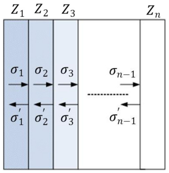
Figure 1.
Reflection and transmission of shock wave in the wave-impedance gradient material.
According to Equations (1) to (4), it can be seen that the wave-impedance matching condition of the wave-impedance gradient material interface directly determines the size and properties of the stress wave.
2.2. Analysis Model of Shock-Wave Propagation
For wave-impedance gradient materials with the same structure, the shock wave generated by the impact point is simplified as a one-dimensional stress wave, and only its propagation in the thickness direction of the target plate is considered, as shown in Figure 1. Within a time interval when the stress wave is transmitted from the generation end to the distal end, the stress in the distal layer can be obtained according to the reflection coefficient and transmission coefficient . From Equation (1) to (2), the following can be deduced:
where ; , , , , are the incident wave intensities at the interface of each layer; are the reflected wave intensities at the interface of each layer; and and are the inter-layer projection coefficient and the reflection coefficient, respectively. Iterate Equation (5) to obtain:
Let be the total transmission coefficient when the incident shock wave passes through the wave-impedance gradient-attenuation region.
The wave impedance and the total gradient attenuation of the surface material of the wave-impedance gradient material are kept constant as , and , respectively. For the wave-impedance gradient material with N layers, it can be assumed that the wave impedance of each layer of material changes as follows:
The wave impedance of the i-th layer material is:
When the wave-impedance gradient material is two layers:
When the wave-impedance gradient material is three layers:
When the wave-impedance gradient material is four layers:
When the wave-impedance gradient material is layers:
Assuming that the surface material of the wave-impedance gradient material is titanium alloy and the back material is nylon, the constant and are determined. The total transmission coefficient of Ti-Ny is 0.206, that of Ti-Al-Ny is 0.236, and that of Ti-Al-Mg-Ny is 0.273. With the increase in the number of layers , the total transmission coefficient approaches the maximum value of 0.339, as shown in Figure 2.
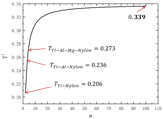
Figure 2.
Variation trend of total transmission coefficient with gradient layer.
Therefore, the continuous change in wave impedance is better than the step change at reducing the attenuation amplitude of the stress and maintaining the stress at a higher level. The stress amplitude has a positive relationship with the impact breaking, melting, and gasification of the projectile, which is conducive to the further improvement of the protection performance of the wave-impedance gradient material.
3. Numerical-Simulation Study
3.1. Validation of Numerical Simulation
Experimental research is the most direct and effective method to solve the problem. However, due to the limitations of the experimental conditions, the data available from the hypervelocity impact experiment are limited. In order to better analyze and obtain its laws, numerical simulation has become a necessary means. In recent years, meshless methods have been developed rapidly, among which the SPH algorithm is typical and has been widely used in the numerical simulation of hypervelocity collisions [25,26,27,28,29,30].
In this paper, the AUTODYN dynamic simulation program was used. In order to expand the variation range of the simulated wave-impedance gradient as fully as possible, titanium alloy, aluminum alloy, magnesium alloy, and nylon were selected as the commonly used engineering-protection materials for the numerical simulation. A 2D model was used for the model verification, and the calculation speed and accuracy were considered. The particle size was 0.1 mm.
Tillotson equation of state was used in the modeling of Al and Ti, where A, a, and b were the fitting constants, B and e0 were the adjustment parameters, and α and β were the material constants. The Steinberg Guinan constitutive model was used, where Y0, Ymax, b, h, β, G0, and Tm were the material parameters. The state equation of Puff was used for the Mg material, where A1, A2, and A3 were the material parameters, and the Von Mises constitutive model was used. The shock-state equation was selected for the nylon material, and the Von Mises constitutive model was also adopted. The parameters of the material model are shown in Table 1, Table 2 and Table 3.

Table 1.
Parameters of Tillotson state equation for titanium and aluminum.

Table 2.
Parameters of Steinberg Guinan model for titanium and aluminum.

Table 3.
Parameters of Puff state equation for magnesium.
During numerical simulations, the selection of the algorithm, material model, and parameters greatly affect the accuracy of the results. Therefore, the correctness of the numerical simulation method should be verified according to the experimental results [31,32].
Figure 3 shows the comparison of the numerical-simulation results and experimental photographs under the same working conditions. The deviation between the numerical simulation results and the experimental results of the debris-cloud-head-extension-distance gradient material was about 3.2%. The deviation between the numerical-simulation results and the experimental results was about 4.9%. The above comparison shows that the selected calculation model and parameters are reasonable.
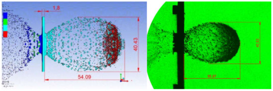
Figure 3.
Comparison of numerical-simulation results and experimental results for protective structures under the same working conditions (5 km/s, 20 μs time).
3.2. Characteristics of Shock Pressure and Internal Energy Transformation under Different Wave-Impedance Distributions
The previous theoretical analysis showed that the continuous change in wave impedance is conducive to reducing the attenuation amplitude of the stress and maintaining the stress at a higher level. However, it is difficult to achieve the continuous change in material wave impedance in both the simulation and the material preparation. The continuous change in wave impedance can only be simulated by increasing the number of material layers with different wave-impedance gradients. In the simulation study of working conditions 1–4, four materials with different wave-impedance characteristics were selected to ensure that the number of material layers was continuously increased under the condition that the total area density of the protective screen was the same, so as to simulate the continuous change in wave impedance and analyze the impact of this change on the hypervelocity-impact response of the projectile. Compared with working condition 1, working condition 5 reduced the nylon material and changed the back material into magnesium alloy, thus reducing the total gradient-attenuation value of the material, which was used to analyze the impact of the total gradient attenuation value on the protection performance. Compared with condition 5, condition 6 reduced the titanium alloy, which was used to analyze the influence of the surface-material-wave-impedance on the protection performance.
The same projectile-impact parameters and protective-screen-area density were adopted for the simulation calculation conditions. The calculation-model parameters are shown in Table 4. The calculation model of calculation conditions 1–4 is shown in Figure 4. In order to obtain the shock-wave pressure at the center of the projectile, gauce points were added to the simulation model, as shown in Figure 4a, so as to record the change in the shock-wave amplitude in the projectile.

Table 4.
Calculation-model parameters.
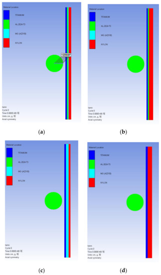
Figure 4.
Calculation model for working conditions 1–4: (a) Ti-Al-Mg-Ny protective screen; (b) Ti-Al-Ny protective screen; (c) Ti-Mg-Ny protective screen; (d) Ti-Ny protective screen.
Figure 5 shows the impact-wave-amplitude changes at different positions in the projectile under the impact of four calculation models at 5 km/s. It can be seen from the figure that the shock wave of the projectile started at the contact surface of the projectile target, and the amplitude gradually attenuated with the increase in the propagation distance.
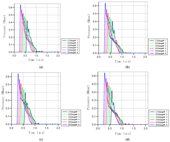
Figure 5.
Shock-wave amplitudes at different positions in the projectile: (a) Ti-Al-Mg-Ny protective screen; (b) Ti-Al-Ny protective screen; (c) Ti-Mg-Ny protective screen; (d) Ti-Ny protective screen.
In order to accurately compare the impact of the continuous gradient change on the shock-wave amplitude, Figure 6 shows the corresponding projectile shock waves of the Ti-Ny, Ti-Al-Ny, and Ti-Al-Mg-Ny shielding materials at the impact speed of 5 km/s. It can be seen that the initial pressure of the shock wave corresponding to the three materials was essentially the same, because the surface material impacted by the projectile target was titanium alloy. The shock-wave amplitude of the three materials decreased with the increase in time, and the decreasing amplitude was Ti-Ny > Ti-Al-Ny > Ti-Al-Mg-Ny, which indicated that the attenuation amplitude of the shock wave in the projectile decreased obviously with the continuous change in the wave impedance, which was consistent with the theoretical analysis.
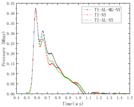
Figure 6.
The change in the projectile-shock-wave amplitude corresponding to the three protective screen materials.
In the process of the hypervelocity impact, part of the kinetic energy of the projectile is converted into the kinetic energy of the debris cloud, and the other part is converted into the internal energy of the material. The internal-energy-conversion ability of the protective-screen material is an important criterion for judging the performance of the protective material. The higher the internal-energy conversion, the better the protective performance. Therefore, the analysis of the internal-energy-conversion characteristics during the interaction between the projectile and the wave-impedance gradient material can be used to effectively judge whether the continuous change in the wave impedance is conducive to improvements in the protection ability; it can also be used to examine the influence of the surface-material wave impedance and the total gradient attenuation value on the protection performance, so as to guide the design of the wave-impedance gradient material. Table 5 shows the corresponding converted internal energy of the five shielding materials, Ti-Ny, Ti-Al-Ny, Ti-Al-Mg-Ny, Ti-Al-Mg, and Al-Mg, under different impact speeds.

Table 5.
Corresponding internal-energy conversion of five protective-screen materials at different impact speeds.
From the results shown in Figure 7, it can be found that under the same impact velocity, the converted internal energy Ti-Al-Mg-Ny > Ti-Al-Ny > Ti-Ny; that, with the continuous change in the wave-impedance gradient, the internal-energy conversion showed a gradually increasing trend. This shows that under the same impact conditions, the continuous change in the wave-impedance gradient of a wave-impedance material with the same surface density can effectively improve the internal-energy conversion during the impact process, thereby effectively reducing the velocity of the debris cloud and reducing the ability of the debris cloud to damage the rear wall. In working condition 4, the internal-energy conversion of the Ti-Al-Mg material was smaller than that of Ti-Al-Mg-Ny, Ti-Al-Ny, and Ti-Ny, which indicated that the increase in the total gradient-attenuation value is conducive to the conversion of kinetic energy to internal energy during hypervelocity impact. Working condition 5 further reduced the wave impedance of the surface materials and the gradient attenuation of the total wave impedance, resulting in the reduced conversion of internal energy. This proves that it is important to comprehensively consider the wave impedance of surface materials and the gradient-attenuation value of total wave impedance when the total area density of materials is fixed in the design process of wave-impedance gradient materials.
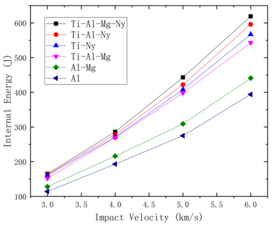
Figure 7.
Internal-energy transformation under different impact conditions.
3.3. Fragmentation Characteristics of Projectilse with Different Wave-Impedance Distributions
The breaking characteristics of projectiles vary under different wave-impedance distributions compared with aluminum alloy. The wave-impedance gradient material changes the shock-wave characteristics of the projectile target. This not only increases the conversion rate of the initial kinetic energy to the internal energy, but also changes the breaking characteristics of the projectile and enhances the space-diffusion ability of the debris. The spatial diffusion of kinetic energy is mainly determined by the fragmentation degree of the projectile during the action of the projectile target. In this part, the numerical simulation method is mainly used to study the impact of the projectile on different wave-impedance gradient materials.
Three kinds of wave-impedance gradient materials, Ti-Al-Mg-Ny, Ti-Al-Ny, and Ti-Ny, which have the same surface density as 1.5-milimeter thick aluminum alloy, were selected for the numerical calculation. In order to prevent the influence of the lateral sparse wave on the impact pulse in the central region of the projectile, a one-dimensional strain-collision model was established to observe the impact of the impedance gradient on the spallation breaking in one dimension. The projectile material was aluminum alloy, the projectile’s thickness was 6 mm, the maximum tensile-stress failure criterion was adopted, the maximum tensile stress that could be withstood was 2.0 GPa, and the impact speed was selected as 3.0 km/s~6.0 km/s. The calculation-model parameters are shown in Table 6.

Table 6.
Calculation-model parameters.
In order to better analyze the fragmentation of the projectile under different impact speeds, the SPH particle size of the projectile was taken as 0.1 mm, as was the SPH particle size of the protective screen. In order to accurately obtain the maximum spallation breaking area of the projectile, observation points were set at the center of the model with intervals of 0.1 mm. The typical calculation-model parameters are shown in Figure 8.
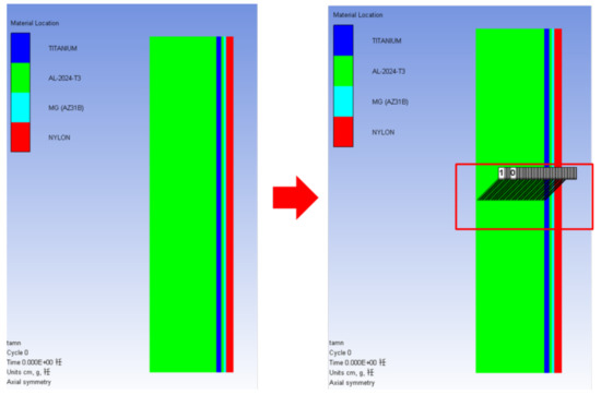
Figure 8.
One-dimensional strain-collision model.
The judgment of spallation breaking can be performed by analyzing the pressure-time-history curve of the typical observation points. A positive value in the time-history curve indicates that the material bears the compressive stress, and a negative value indicates that the material bears the tensile stress. When the tensile stress is greater than the set spallation-breaking strength, the material undergoes spallation breaking, as shown in Figure 9.
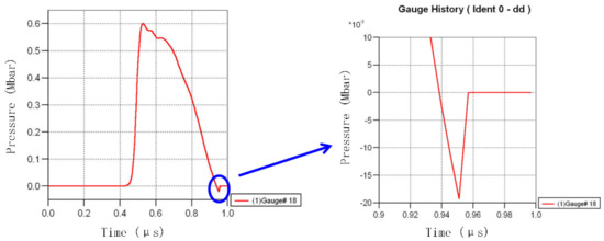
Figure 9.
Pressure−time−history curve of observation point at spalling position.
The typical numerical calculation results of the projectile’s impact on three kinds of wave-impedance gradient materials are shown in Figure 10. The statistics of the spallation fracture areas of the projectile’s impact on three kinds of wave-impedance gradient materials under the speed conditions of 3 km/s, 4 km/s, 5 km/s, and 6 km/s are shown in Table 7.
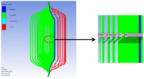
Figure 10.
Calculation results of one-dimensional strain collision of aluminum alloy material (left) and Al/Mg gradient material (right).

Table 7.
Calculation results of one-dimensional strain-collision-spalling region of aluminum alloy materials and Al/Mg gradient materials.
It can be seen from Figure 11 that the fragmentation area of the projectile corresponding to the three materials increased with the increase in the impact speed, because the higher the speed, the greater the shock-wave strength and the greater the fragmentation of the projectile. At the same speed, the fragmentation area of the projectile was Ti-Al-Mg-Ny > Ti-Al-Ny > Ti-Ny. It can be seen that the continuous change in the gradient obviously increased the tensile fragmentation area of the projectile, which was conducive to the diffusion of the projectile fragments, thus improving the spatial-diffusion ability of the kinetic energy.
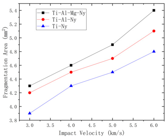
Figure 11.
The fragmentation area of the projectile under different impact parameters.
4. Conclusions
In this paper, a theoretical analysis and numerical simulation methods were used to study the hypervelocity impact of a projectile on a wave-impedance gradient material, establish an analysis model of shock-wave propagation, and quantitatively study the impact law of the wave-impedance gradient change and continuous change in impact pressure, internal-energy conversion, and projectile-breaking characteristics. The main conclusions are as follows:
- (1)
- By analyzing the propagation characteristics of shock waves in wave-impedance gradient materials, the total-transmission-coefficient model of the incident shock waves passing through the wave-impedance-gradient-attenuation region was established. According to the model, when the surface material of the wave-impedance gradient material is titanium alloy and the back material is nylon, the total transmission coefficient increases from 0.206 to the maximum value of 0.339 with the continuous change in the gradient. It was directly proven that the continuous change in the wave impedance is better than the step change at reducing the attenuation of the amplitude of the shock wave in the projectile, keeping the stress amplitude of the shock wave at a higher level, improving the impact-breaking, melting, and gasification degree of the projectile, and, thus, enhancing the protective performance of the wave-impedance gradient material.
- (2)
- Titanium alloy, aluminum alloy, magnesium alloy, and nylon were selected to establish the numerical-simulation model. The numerical-simulation analysis showed that the decreasing amplitude of the shock wave with time was Ti-Ny > Ti-Al-Ny > Ti-Al-Mg-Ny, the transformed internal energy was Ti-Al-Mg-Ny > Ti-Al-Ny > Ti-Ny, and the projectile-breaking area was Ti-Al-Mg-Ny > Ti-Al-Ny > Ti-Ny.
- (3)
- Through the numerical simulation, it was proven that the continuous change in the wave-impedance gradient can effectively reduce the attenuation of the shock-wave amplitude, reduce the kinetic energy of the debris cloud, and increase the fragmentation degree of the projectile, so as to improve the conversion and spatial-diffusion ability of the projectile’s kinetic energy and effectively improve the protective ability of the material.
Through this study, the design principles of wave-impedance gradient materials were clarified. In the future, more hypervelocity-impact experiments are needed to further verify the hypervelocity-impact characteristics and protective performances of these materials. In addition, the shield design of different surface-density wave-impedance gradient materials could be carried out to meet the protection requirements of different types of spacecraft.
Author Contributions
Conceptualization, Z.Y. and Z.G.; methodology, W.L.; formal analysis, Z.Y.; investigation, Q.W.; resources, Z.Y.; writing—original draft preparation, Z.Y.; writing—review and editing, L.Y.; project administration, Y.M. All authors have read and agreed to the published version of the manuscript.
Funding
This work was supported by the State Key Basic Research Program of China (Grant No. 61xxxx02), and National Space Technology Pre research Project (No. D02xx08).
Institutional Review Board Statement
Not applicable.
Informed Consent Statement
Not applicable.
Data Availability Statement
Not applicable.
Conflicts of Interest
The authors declare no conflict of interest.
References
- Wu, Q.; Zhang, Q.M.; Long, R.R.; Gong, Z.Z. Experimental Study on Ultra-high Speed Impact Protection Performance of Active Whipple Structure. Explos. Impact 2021, 41, 021406. [Google Scholar]
- Schonberg, W.P.; Tullos, R.J. Spacecraft wall design for increased protection against penetration by orbital debris impacts. AIAA J. 1990, 29, 2207–2214. [Google Scholar] [CrossRef]
- Tang, E.L.; Zhao, L.L.; Han, Y.F.; Chen, C.; Chang, M. Research on the electromagnetic propa-gating characteristics of hypervelocity impact on the target with aperture and different potential conditions. Aerosp. Sci. Technol. 2020, 107, 106274. [Google Scholar] [CrossRef]
- Li, T.; Chen, L. Historical-orbital-data-based method for monitoring the operational status of satellites in low Earth orbit. Acta Astronaut. 2018, 151, 88–94. [Google Scholar] [CrossRef]
- Krag, H.; Serrano, M.; Braun, V.; Kuchynka, P.; Catania, M.; Siminski, J.; Schimmerohn, M.; Marc, X.; Kuijper, D.; Shurmer, I.; et al. A 1 cm space debris impact onto the sentinel-1a solar array. Acta Astronaut. 2017, 137, 434–443. [Google Scholar] [CrossRef]
- Christiansen, E.L. Handbook for Designing MMOD Protection: NASA JSC-64399; NASA: Washington, DC, USA, 2009.
- Gong, Z.Z.; Zhao, Q.Y.; Li, M. The Frontier Problem and Prospect of Space Debris Protection Research. Space Debris Res. 2019, 19, 2–13. [Google Scholar]
- Cherniaev, A.; Telichev, I. Sacrificial bumpers with high-impedance ceramic coating for orbital debris shielding:a preliminary experimental and numerical study. Int. J. Impact Eng. 2018, 119, 45–56. [Google Scholar] [CrossRef]
- Destefanis, R.; Schaefer, F.; Lambert, M.; Faraud, M. Selecting enhanced space debris shields for manned spacecraft. Int. J. Impact Eng. 2006, 33, 219–230. [Google Scholar] [CrossRef]
- Cour-Palais, B.G.; Crews, J.L. A multi-shock concept for spacecraft shielding. Int. J. Impact Eng. 1990, 10, 135–146. [Google Scholar] [CrossRef]
- Christiansen, E.L.; Kerr, J.H.; De La Fuente, H.M.; Schneider, W.C. Flexible and deployable meteoroid/debris shielding for spacecraft. Int. J. Impact Eng. 1999, 23, 125–136. [Google Scholar] [CrossRef]
- Wu, Q.; Zhang, Q.M.; Long, R.R. Potential space debris shield structure using impact-initiated energetic materials composed of polytetrafluoroethylene and aluminum. Appl. Phys. Lett. 2016, 108, 101903. [Google Scholar] [CrossRef]
- Ren, S.Y.; Zhang, Q.M.; Wu, Q.; Long, R.R.; Gong, L.F.; Lu, Y.Y. A reactive material double-bumper shield for centimeter sized projectile. Int. J. Impact Eng. 2021, 158, 104028. [Google Scholar] [CrossRef]
- Ren, S.Y.; Zhang, Q.M.; Gao, F.; Wu, Q.; Liang, H.Z.; Liu, W.J. Impact resistance mechanism of reactive material bumper for spacecraft Whipple shield: Experiments and numerical simulations. Aerosp. Sci. Technol. 2022, 126, 107646. [Google Scholar] [CrossRef]
- Wang, Y.; Zhang, T.; He, Y.; Ye, J.; Zhang, H.; Fan, X. Analysis of Damage of Typical Composite/Metal Connecting Structure in Aircraft under the Influences of High-Velocity Fragments. Appl. Sci. 2022, 12, 9268. [Google Scholar] [CrossRef]
- Fowler, K.; Teixeira-Dias, F. Hybrid Shielding for Hypervelocity Impact of Orbital Debris on Unmanned Spacecraft. Appl. Sci. 2022, 12, 7071. [Google Scholar] [CrossRef]
- Zhao, B.; Zhao, J.; Cui, C.; Duan, Y. Hydrodynamic Ram Effect Caused by Debris Hypervelocity Impact on Satellite Tank. Appl. Sci. 2019, 9, 4200. [Google Scholar] [CrossRef]
- Lu, Y.; Zhang, Q.; Xue, Y.; Shang, C.; Liu, W.; Ren, S.; Long, R. Hypervelocity Impact Cratering on Semi-Infinite Concrete Targets of Projectiles with Different Length to Diameter Ratios. Appl. Sci. 2020, 10, 3910. [Google Scholar] [CrossRef]
- Zhao, B.; Zhao, J.; Cui, C.; Wang, Y. Shock Initiation of a Satellite Tank under Debris Hypervelocity Impact. Appl. Sci. 2019, 9, 3957. [Google Scholar] [CrossRef]
- Christiansen, E.L. Meteoroid/Debris Shielding: TP-2003-210788; NASA: Washington, DC, USA, 2003.
- Wen, K.; Chen, X.W.; Di, D.N. Modeling on the shock wave in spheres hypervelocity impact on flat plates. Def. Technol. 2019, 15, 457–466. [Google Scholar] [CrossRef]
- Hou, M.Q.; Gong, Z.Z.; Xu, K.B.; Zheng, J.-D.; Cao, Y.; Niu, J.-C. Experimental study on Hypervelocity impact characteristics of thin plate with density gradient. Acta Phys. Sin. 2014, 63, 024701. [Google Scholar]
- Zhang, P.L.; Song, G.M.; Gong, Z.Z.; Tian, D.B.; Wu, Q.; Cao, Y.; Li, Y.; Li, M. Impact characteristics of Whipple structure reinforced with Al/Mg wave impedance gradient material. Explos. Shock Waves 2019, 39, 8. [Google Scholar]
- Zhang, P.L.; Gong, Z.Z.; Tian, D.B.; Song, G.; Wu, Q.; Cao, Y.; Xu, K.; Li, M. Comparison of shielding performance of Al/Mg impedance-graded-material-enhanced and aluminum Whipple shields—ScienceDirect. Int. J. Impact Eng. 2019, 126, 101–108. [Google Scholar] [CrossRef]
- Liu, G.R.; Liu, M.B. Smoothed Particle Hydrodynamics: A Meshfree Particle Method; World Scientific: Singapore, 2003. [Google Scholar]
- Bashurov, V.V.; Bebenin, G.V.; Ioilev, A.G. Numerical simulation of rod particles hypervelocity impact effectiveness at various attack angles. Int. J. Impact Eng. 1997, 20, 79–88. [Google Scholar] [CrossRef]
- Hu, K.; Schonberg, W.P. Ballistic limit curves for non-spherical projectiles impacting dual-wall spacecraft systems. Int. J. Impact Eng. 2003, 29, 345–355. [Google Scholar] [CrossRef]
- Wang, Q.T.; Wu, K.G.; Li, B.H.; Chen, Z.Y. Fragmentation properties of spherical projectiles impacting at hypervelocity. J. Vib. Shock 2014, 33, 46–50. [Google Scholar]
- Wang, Q.T.; Wu, K.G.; Chen, Z.Y. Fracture effect of Thin plate structure under ultra-high speed Forward Impact of long cylindrical Rod. J. Vib. Shock 2017, 36, 7. [Google Scholar]
- Zhang, C.B.; Di, D.N.; Chen, X.W.; Wen, K. Characteristics structure analysis on debris cloud in the hypervelocity impact of disk projectile on thin plate. Def. Technol. 2019, 16, 299–307. [Google Scholar] [CrossRef]
- Wu, Q.; Zhang, Q.M.; Long, R.R.; Gong, Z.Z. Numerical simulation of the impact characteristics of protective structures with energetic active materials at ultra-high speed. J. Vib. Shock 2021, 40, 202–210. [Google Scholar]
- Song, M.M.; Wu, Q.; Gong, Z.Z.; Zhang, P.L.; Cao, Y. Research on the characteristics of debris cloud protected by wave impedance gradient under ultra-high speed impact. Explos. Shock Waves 2021, 41, 021405. [Google Scholar]
Publisher’s Note: MDPI stays neutral with regard to jurisdictional claims in published maps and institutional affiliations. |
© 2022 by the authors. Licensee MDPI, Basel, Switzerland. This article is an open access article distributed under the terms and conditions of the Creative Commons Attribution (CC BY) license (https://creativecommons.org/licenses/by/4.0/).