Article

Design and Simulation of a Solar Tracking System for PV

by
Fatima Zohra Baouche
1,*,
Bilal Abderezzak
1,*,
Abdennour Ladmi
2,
Karim Arbaoui
2,
George Suciu
3,
Traian Candin Mihaltan
4,
Maria Simona Raboaca
5,6,7,*,
Sebastian Valeriu Hudișteanu
8,* and
Florin Emilian Țurcanu
8,*
1
Laboratoire de l’Énergie et des Systèmes Intelligent (LESI), University of Khemis Miliana, Road of Theniet el Had, Khemis Miliana 44225, Algeria
2
Department of Technology, Faculty of Sciences and Technology, University of Khemis Miliana, Road of Theniet el Had, Khemis Miliana 44225, Algeria
3
R&D Department Beia Consult International Bucharest, 041386 Bucharest, Romania
4
Faculty of Building Services, Technical University of Cluj-Napoca, 400114 Cluj-Napoca, Romania
5
National Research and Development Institute for Cryogenic and Isotopic Technologies—ICSI Rm. Vâlcea, Uz-inei Street, No. 4, P.O. Box 7 Râureni, 240050 Rm. Vâlcea, Romania
6
Faculty of Electrical Engineering and Computer Science, Ștefan cel Mare University, 720229 Suceava, Romania
7
Doctoral School, University Politehnica of Bucharest, Splaiul Independentei Street, No. 313, 060042 Bucharest, Romania
8
Faculty of Civil Engineering and Building Services, Gheorghe Asachi Technical University of Iasi, 700050 Iași, Romania
*
Authors to whom correspondence should be addressed.
Appl. Sci. 2022, 12(19), 9682; https://doi.org/10.3390/app12199682
Submission received: 23 August 2022 / Revised: 21 September 2022 / Accepted: 23 September 2022 / Published: 27 September 2022
(This article belongs to the Special Issue Urban Sustainability and Resilience of the Built Environments)

Abstract

:
After installing a solar panel system, the orientation problem arises because of the sun’s position variation relative to a collection point throughout the day. It is, therefore, necessary to change the position of the photovoltaic panels to follow the sun and capture the maximum incident beam. This work describes our methodology for the simulation and the design of a solar tracker system using the advantages that the orientation and efficiency of the PV panel offer due to the latitude and the number of hours of sunshine in the testing area. This proposed methodology is experimentally validated through the implementation of a single-axis solar tracker at a specific location (36.261° latitude), which allowed the incorporation of a high-availability tracking mechanism, low precision, and low cost. Based on the results, the feasibility of this type of solar tracker for latitudes close to 36° was demonstrated, as this tracking system costs less than traditional commercial systems. Furthermore, this system increased the collection efficiency compared to a fixed device. Our results provide an excellent platform for engineering technology researchers and students to study the design theory of a sun-tracking solar system.

1. Introduction

Much scientific research has been carried out, not only in the field of solar energy conversion in general but also in a very specific sector of the latter, which is none other than photovoltaic technology. In this case, the design, optimization, and realization of systems based on this technology are current issues since they can lead to better exploitation of solar energy if they are correctly done. One of the paths taken is increasing the solar radiation captured since maximum efficiency is achieved when the incident light is perpendicular to the cells of the photovoltaic panels: this is the concept of “solar tracking”. Therefore, the energy efficiency of these systems depends on the climate conditions of solar radiation, ambient temperature, and wind speed, the matching of the system with the load, and the appropriate placement of the solar panels. Most solar panels are used in a stationary position and therefore do not consistently output the maximum amount of power they can produce.
To obtain the maximum efficiency from photovoltaics panels, it was necessary to study the problem of PV orientation, which requires using a solar tracker connected to the photovoltaic system. A solar tracker will track the sun throughout the day and adjust the angle of the solar panel so that the sun is normal, typical to the solar panels at all times. There are two ways to maximize the useful energy rate: by optimizing the conversion and degree of absorption and increasing the incident radiation rate by employing mechanical steering systems. In this context, in our project, we decided to realize such a system, which is commonly called a “solar tracker”.
A solar tracker is a photovoltaic installation placed on a supporting structure composed of a motor. It makes it possible to direct the solar panels throughout the day toward the sun to capture the maximum sunshine. Therefore, solar trackers can be classified into two main categories depending on the type of control and the sensitivity of the sensors or the positioning system they incorporate [1,2,3]. They can also be distinguished by two tracking techniques: The MPPT (maximum power point tracking) method which is based on an algorithm to find the maximum power curve of the photovoltaic panel, or the sun tracking system, which is based on the orientation of solar panels throughout the day to better exploit the photovoltaic cells [4,5].
Much research was conducted to improve and increase the production of electrical energy through the transformation of solar energy. Among this research, we can cite the work of Robert H. Dold and F. R. Rubio et al. [6]. In 2007, they described a 2-axis solar tracker capable of withstanding extreme weather conditions, which tracks the elevation and azimuth movement. In 2008, J.Rizk [6] indicated the potential advantages of a simple solar tracking system using a stepper motor and light sensor. A solar tracking system was designed, implemented, and experimentally tested with fairly conclusive results. Hossein Mousazadeh, in 2009 [6], discussed the different sun tracking systems’ advantages and disadvantages. The most effective sun tracking device was found in the form of polar and azimuth/elevation axes. In 2010, Nader Barsoum [6] reported that his research has proven that the single-axis sun tracking system can increase the energy output by about 20%, while the dual-axis tracking system can increase the output by 40%. In 2012, L. Kancevica [6] noted that thanks to the sun tracking device, the solar radiation continuously hit perpendicular to the collector of the flat plate, which finally produced 1.4 times more thermal energy on average compared to the collector stationary of the same size. In 2013, Mostefa Ghassoul [6] described constructing and testing a cost-effective, innovative sun tracking system to extract maximum solar energy. The latter was designed to be driven by a PIC 18F452 microcontroller. The system was based on two mechanisms: the first is the search mechanism (PILOT), which locates the position of the sun and the second mechanism (intelligent PANELS) aligns with the PILOT only if the maximum possible energy could be extracted.
Thereby, the research results from the article [7,8,9,10,11] confirm that the orientation of solar panels can increase the efficiency of the conversion system by 20% up to 50%, which significantly increases electricity production. In [11], there was a study of a three-phase inverter representing an essential part of the photovoltaic systems, which allowed us to take an idea on the conditioning and the simulation of the motor used in our realized prototype. Afterward, many research works have studied the optimization and design of the sun tracking method to maximize the exposure of cells to sunlight by keeping the solar module’s active surface perpendicular to the solar radiation. In 2018, the authors of the article [12] presented a comprehensive examination of the solar tracking system’s potential in solar energy applications. Their explanation helps to give an overview of drive system design parameters, construction, types, and techniques covering different applications of use. They explained the two main types of solar tracking systems: the single-axis solar tracking system and the dual-axis solar tracking system. Their paper shows that in recent research studies, 42.57% of the studies have discussed and presented single-axis tracking systems, while 41.58% of these studies reported on dual-axis tracking systems. As well as in the solar tracking techniques, azimuth and elevation tracking reached 16.67% utilization, horizontal tracking 16.67%, azimuth tracking 10%, polar tracking 16.67%, and utilization 4.44%. This encouraged us to continue to improve the modeling results of the different blocks of our methodology and improve the other blocks’ modeling results [13].
Several electronic systems for the control and piloting of bi-axial solar trackers of photovoltaic power plants were developed and tested by [14,15,16]. As in our case, the tracking is managed by a PC software application with a user-friendly graphical interface. The software’s design is designed to calculate the circadian orbit of the sun and consequently to move the solar panels to keep the panel surface always perpendicular to the solar rays, thus improving the efficiency of energy production. For example, a new photovoltaic (PV) sun tracker design methodology has been explained and relied on by [14], who used the advantages that the orientation and efficiency of the PV panel offer due to the latitude of the installation zone. They experimentally validated the proposed design methodology and proposed a design methodology via the implementation of a solar tracker with dual axes at a specific location (27.5° latitude). Their method enables the incorporation of a high-availability, low-accuracy, and low-cost tracking mechanism. From their results, we can conclude that this system increases the collection efficiency by 24% with respect to a fixed device. Based on an orientation efficiency chart, the proposed methodology can be applied to control our solar tracker system.
The scientific content of [16] allowed us to get a general idea of the most commonly used solar tracking systems, and we identified the systems that provide benefits such as higher efficiency, higher tracking accuracy, easy installation, and cost-effectiveness. Their study reveals that double axis ST in the form of polar-axis and azimuth/elevation featuring the solar movement models and the dynamic closed-loop feedback control is the most effective and generally gives more than a 40% improvement in energy return compared to fixed PV panels. Moreover, they showed that large systems significantly reduce costs and save on materials. The energy consumed by the moving fixtures is mostly low (2–5% of the collected energy), but this could be higher if no optimization is performed. That is why we have optimized all power-saving hardware and software settings from the early stages of system development to avoid waste of material and over-consumption of power by tracking units.
Another study by [17] presents an overview of the advancements realized in the world of solar tracking systems. They emphasized the performance analysis of dual-axis solar tracking systems equipped with different designs and techniques that have evolved in recent years. Some conclusions drawn in their paper are stated below: the dual-axis solar tracking systems are generally more efficient than their single-axis and fixed counterparts. These systems also demand maintenance due to the presence of rotating components. Furthermore, these systems contain more complex design and control mechanisms. The solar system’s performance depends on many physical factors and so does the choice of use of tracking.
In this paper, we present the steps of designing and implementing the prototype of a single-axis solar tracker that we designed and built at our university. The design of the single-axis solar tracker has been made by several researchers, as mentioned in the previous summary of the literature. But still, some shortcomings must be avoided to improve the system, especially concerning the geographical parameters of each installation area. Our project was put into reality following the need of our university for this system to be used in the various premises containing PV panels. This necessity forced us to start collecting knowledge in circuit theory, power electronics, microcontrollers, machine electricity, and solar energy to design and simulate the system. The Matlab/Simulink simulation provided an excellent platform to explore different designs for the sun-tracking solar energy system. After testing and verification using simulations, a prototype system was built in the laboratory using our hardware and programs. The university’s weather station collects parameters and real-time data on the installation area. Given the high number of models created and the mathematical calculations performed, we present only a part of the scientific result obtained in this paper. Our complete prototype of the single-axis solar tracker is characterized by the fact that it contains in the control circuit a control device assembled and programmed by us in the laboratory to allow the pivoting of the photovoltaic panel and force it to follow the sun’s curve. Thus, we have developed our mathematical models allowing translating of the behavior of the components constituting the prototype, such as the model of the direct current motor block (servomotor); the model of the quantity of effective radiation; the model of the sun, and the model of the photovoltaic panel.
In particular, our work aims to optimize an existing, designed by us, fully-hardware setup by completely replacing the classic electronic board with the designed software to communicate, using a serial port, with Arduino electronic boards for tracker motors driving. The models were developed using MATLAB/Simulink to track a photovoltaic module and achieve optimal operational efficiency. The multi-controller is programmed to detect sunlight by LDR and operate two actuators to position the solar panel where it can receive maximum sunlight.

2. Methodology

This paper collects some results of research work, part of which is carried out as part of a research project, “PRFU: University Training Research Project”, with the participation of [18]. The simulation of our models was carried out using the software “MATLAB-SIMULINK”, which allowed us to create a library of specialized simulation blocks. The annual meteorological data was collected through the meteorological station installed at the University of Khemis Miliana. The prototype allowed tracking the movement of the sun in real-time.
To maximize actual PV production in the field, solar trackers must meet several dimensions during the different phases of the PV project life: design, installation, operation, and maintenance. The challenges are many and diverse, ranging from the lay of the land to the need for local content, local workforce skills, weather conditions, and budget constraints. The efficient performance of a solar tracker requires comprehensive realizations.
Our work is based on a new idea by designing an automatic microcontroller-based solar tracker with a hybrid algorithm comprising both active and chronological algorithms for locating the sun’s position. This hybrid algorithm combines both mathematical models and sensors to determine the precise sun’s position and thereby harness optimal solar energy for all weather conditions.
Experimental results show that the hybrid solar tracking algorithm can yield higher solar power than traditional active and chronological algorithms. The solar tracking process is fully automated, maximizing the collection and management of solar energy for the solar system.
The proposed solar tracker has light-dependent resistors (LDRs), an Arduino microcontroller connected with Wi-Fi, a servo motor, a current sensor, and a solar panel with a supporting metallic servo bracket. This electromechanical system consists of one driver with a servo motor for rotating in east and west directions. The solar panel produces a voltage proportional to the sunlight intensity, while the LDRs determine the system misalignment and send signals to the microcontroller, which in turn automatically adjusts the motors to correct the solar panel position.
Active and chronological algorithms are employed in solar tracking. The active algorithm is a closed-loop tracking mechanism based on the control principle with feedback. A light sensor, which detects sun brightness, acts as the input to the system controller. The acquired values are then analyzed by the microcontroller, which controls the motor motion to orientate the solar panel towards the sun. While the active solar tracker produces high tracking accuracy during clear and sunny days, its performance may degrade when the weather is cloudy or when the light sensor is sheltered. Conversely, the chronological algorithm controls the solar panel movement by identifying the sun’s path using sun tracking mathematical models. The microcontroller calculates the sun’s position and directs the motor to move the solar panel towards the sun at preset time intervals.
In summary, with a large-scale implementation, the proposed hybrid solar tracker can harness optimal solar energy for all weather conditions, thereby considerably cutting electricity costs for public and private organizations.
To evaluate the performance of active, chronological, and hybrid algorithms for solar tracking, experiments were conducted. The solar tracker prototype must be in an open field where it can receive sunlight throughout the day. Voltage measurements were taken from the morning at 4 a.m. to the evening at 8 p.m. at every 60-min interval. Readings from the traditional fixed-mount solar panel were also recorded to determine the baseline voltage. Subsequently, an analysis was performed to determine the energy generated, consumed, and gained by the hybrid solar tracker.

2.1. Assumptions

Our research on the tracking system showed us that, in reality, they are from the same capacity compared to a static configuration and will produce more energy at any point in time, but at what cost? When talking about the price, we have to do a test for 10 years of operation. Thus, we must add the cost of the land into the calculations without forgetting to consider the electricity price, which increases every year, and the state degradation of the PV panels, which degrade every year. Therefore, we must consider the average output per kW installed and the maintenance price for the tracking system every year. Finally, we must calculate the cost per watt supplied and installed for the static system and tracker system. Moreover, that question can be asked in reverse. How much does the by-watt price have to drop before the static system becomes more viable than the tracker system?
When comparing to ascertain what is the best system, static versus tracking, many assumptions need to be made in addition to the reality of actual energy production and how it matches with site loads, etc. Our scientific research confirms that many assumptions are common between the static system and the tracker system, but some are not. Based on the assumptions made, we can say that the tracker system is more economically feasible.
Compared to fixed panels, the advantage of mobile panels is that the sun moves continuously during the day, while a PV panel is fixed in its position, thus losing a considerable amount of energy that might be available. When a photovoltaic panel is fixed in relation to the ground and oriented towards the south, its energy yield is not constant during the day. At the start and end of the day, the poor radiation angle of the panel reduces the efficiency of electricity production [11,12,13,14,15,16,19].

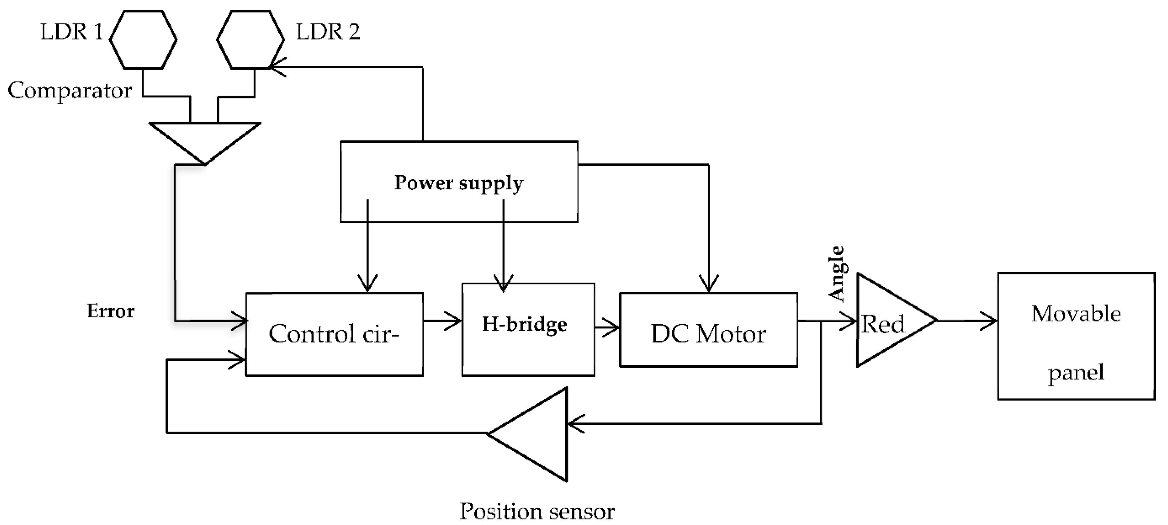
2.2. Block Diagram of a Single-Axis Tracker

The prototype of the tracker that we have realized consists of an electromechanical structure to support the solar panel and direct it in the direction of the perpendicular radiation of the sun on an axis of two East-West directions.
The tracking system essentially consists of two parts: The control or command part (the physical quantities and the solar radiation follow the sun and position the turret optimally) and the operative part (elevation). The control or programming units are used to process the position information of the sun to transmit it to the actuators to track the sun, as well as to detect operating anomalies and perform equipment safety operations. It also performs other functions, such as the control of the system’s mechanical movements by limiting the rotation angles from (0° to 180° on the horizontal) and the panel’s orientation at the end of the day towards the starting position of the system.
The role of the operating or electronic block is to ensure that the solar radiation is always perpendicular to the panel. It, therefore, relies on systems allowing the reception of orders sent by the calculator, their conversion into electrical signals, their transmission to the articulated mechanical system, and the activation of the motor. As shown in the block diagram in Figure 1, when the tracking system steers the solar panels by rotating them in the direction of the sun and maintaining an ideal angle based on two light-dependent resistors (LDR) and a motor, the electrical power per square meter is maximized [20].
The two LDRs are used in our work to capture the light in East-West directions. Each LDR will supply the controller an analog signal depending on the lighting through the voltage divider Vout, given by Equation (1), with an R1 resistance LDR and R2 resistance standard. The controller changes the motor direction [21,22,23,24,25].
V o u t = R 2 R 1 + R 2 V c c                                
The principle is to notice that the light received by the two LDR photoresistors is identical as soon as the sensor is oriented in the axis of the light. Therefore, we measured the light received by each photoresistor by measuring the voltage at their terminals. This measurement is carried out by connecting the ports pin1 to 2 of the card. The program then compares these voltages ordering the servo motor to rotate in the direction of the photoresistor(s) that receives the least light. We used a resistor of 1 kΩ to measure the voltage change between the photoresistor and a resistor of 1 kΩ (voltage divider) placed on the control unit (Arduino card).
Our MATLAB modeling requires describing the models of the different design blocks [18]: The model of the D.C. motor (servo motor) with a P.I.D. controller (proportional integral derivative), the model of the chopper to vary the voltage, the model of the radiation quantity falling on the solar panel, the model of the sun and the model of the photovoltaic panel.

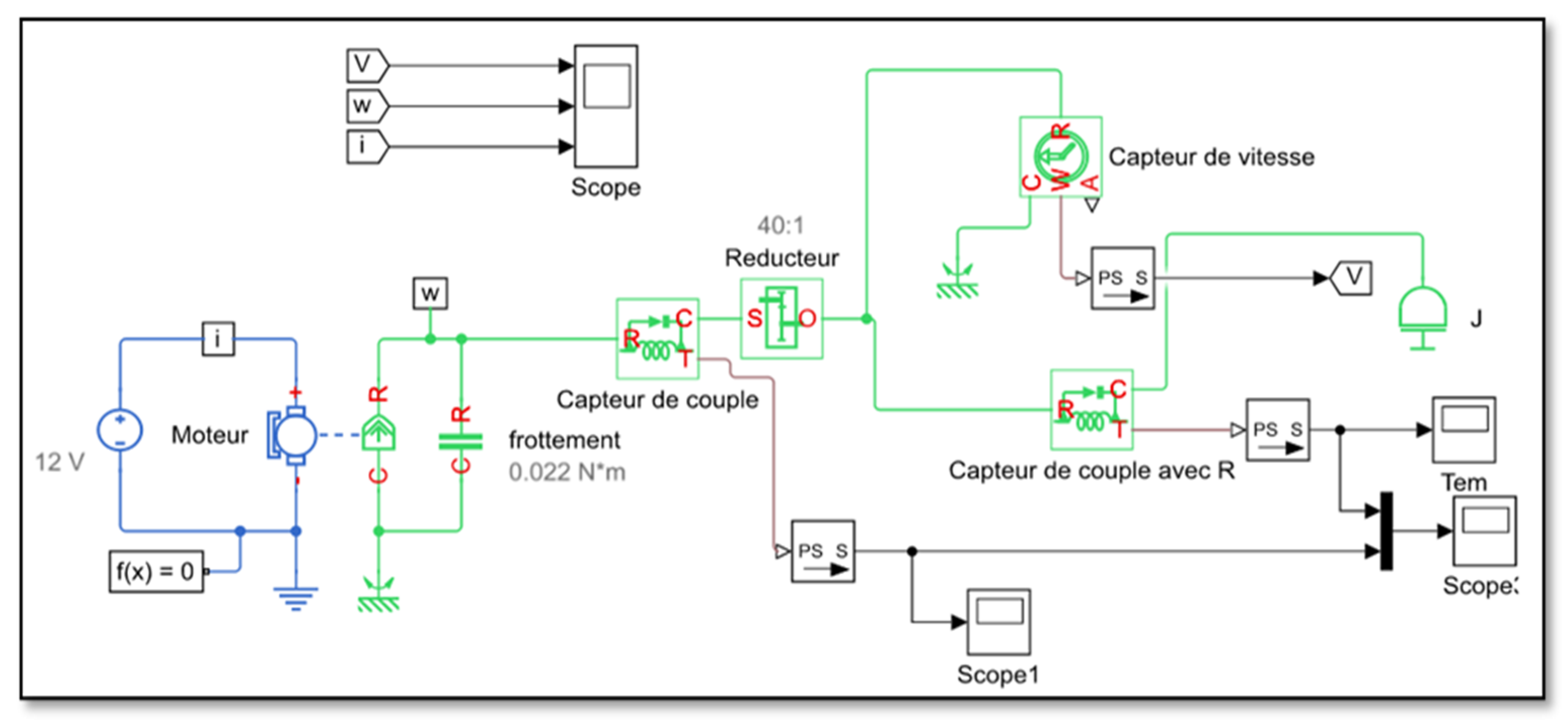
2.3. D.C. Motor Block Controlled by a Chopper

To create the model of the D.C. motor (servomotor), we took into account its 04 constituents and their characteristics which are: A direct current electric motor with rotation in two directions, a reduction gear train actuating the rudder of the out axe, an electronic circuit of the motor control, and a potentiometer.
The creation of our models of the physical system of the engine in the Simulink environment was made using the simulator SimScape (physical systems simulation), which constitutes an effective method for developing the mathematical model of our physical system by creating a multi-domain diagram based on physical connections.
A DC chopper or DC-to-DC converter is the most efficient method as it involves only a one-stage conversion. A fixed D.C. voltage U coming from a power supply is converted into an adjustable D.C. voltage V by a control signal Ucom with a variable duty cycle. The chopper’s role in the solar tracker system is to vary the rotational speed of the D.C. motors. The equivalent model of a motor contains a resistance (Rm), an inductance (Lm), and an electromotive force (E). In addition, the protection elements such as freewheeling diodes are necessarily added [26,27,28]. The steps below are taken into consideration while creating the model of the D.C. motor [29].
-
Variation of the speed for a motor by the P.W.M. (pulse width modulation) command.
-
Voltage reversible chopper.
-
The average value of the supply voltage.
-
Direction inversion control.
The advantage of a P.I.D. regulator is its dynamic performance, adjustment precision, and stability. The elements of this regulator are a combination of P (proportional), I (integral), and D (derivative) actions chosen according to the type of application. For example, our prototype used it to monitor the motor’s position [30].

2.4. Effective Radiation Quantity on the Solar Panel and Calculation of Solar Irradiance

To simulate solar radiation from a different angle than the photovoltaic panel, a simple program was written to obtain the practical relationship between the sun and the falling radiation. Figure 2a shows the equivalent Simulink block diagram that was used to simulate the angle between the sunlight and the photovoltaic panel based on Equation (2) [31,32]. The fixed panel is always parallel to the ground at 45° c.d. 0° for sunrise and 180° for sunset. At sunrise, the sun’s angle starts at 0°, and at sunset, it is at 180 °C. To follow the change in the amount of radiation and temperature that falls on the ground during the day, we have created a model that simulates the evolution of the angle of the sun with time using the real data downloaded from the site PV system. Figure 2b represents the Simulink block diagram used.
G e f = G ( ( θ s θ p ) + 180 180 )                                
where Gef is the effective radiation, G is the solar radiation, θs is the sun angle, and θp is the panel angle.

3. Design and Implementation

Our prototype of the solar tracker was made by starting with schematizing its general configuration. As we explained previously, it consists of three large blocks: the electronic control block, which contains the relay module provided by the Arduino card; the mechanical movement block; and the power supply and electrical power block. In the photovoltaic panel design, it was replaced by a wooden frame of size 40 × 27 cm.

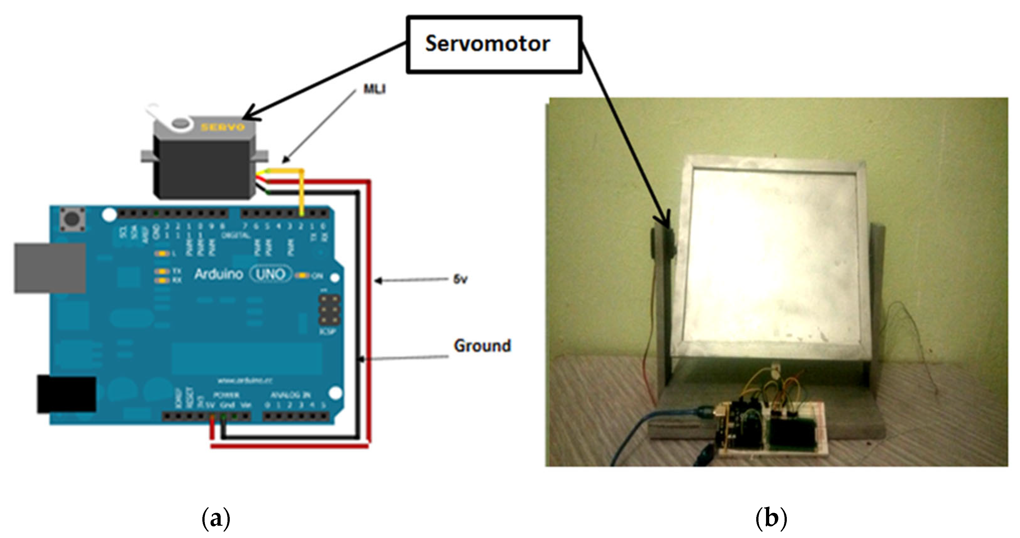
3.1. Electronic Control

This part mainly includes components and electrical circuits to control our solar tracker system. The latter can be defined as a microprocessor-type information processing unit to which internal peripherals have been added, allowing the assembly to be carried out without the need for external components [21]. An Arduino board is a brand that covers hardware-free boards on which there is a microcontroller. Their free license allowed us to program microcontrollers that exist in the different cards as we wanted to analyze and produce electrical signals that can be used for different tasks, including the control and management of electronic processes and instruments [21]. Microcontrollers have reduced performance but are small in size and consume little power. Although the Arduino card was chosen because of its open-source architecture and the ease of connecting to the computer with a simple USB cable. This cable provides both the card power supply and serial communication [33,34,35]. The Arduino card is programmed via a software interface in pseudo-C language. Once the program has been written, it is sent to the card, which can then operate independently (without connection to the computer). To display the numerical or textual information produced by the Arduino card, we connected it to a computer on the one hand and to a liquid crystal display (LCD) on the other hand to be able to operate autonomously away from the computer. In our prototype, we used a display compatible with the Hitachi HD44780 driver.

3.2. Servomotor

Figure 3a shows the mechanical structure of the servomotor. Therefore, Figure 3b shows how we connected the servomotor to the Arduino card. Table 1 collects the characteristic parameters of the servomotor we used in our assembly.
To give us a clear idea of the hardware part, it was preferable to use the ISIS program to simulate the block diagram shown in Figure 4. The signal detected at the output of the Arduino card is visualized using the ISIS program, which is used afterward as the servo motor control signal (P.W.M.).

4. Results and Discussion

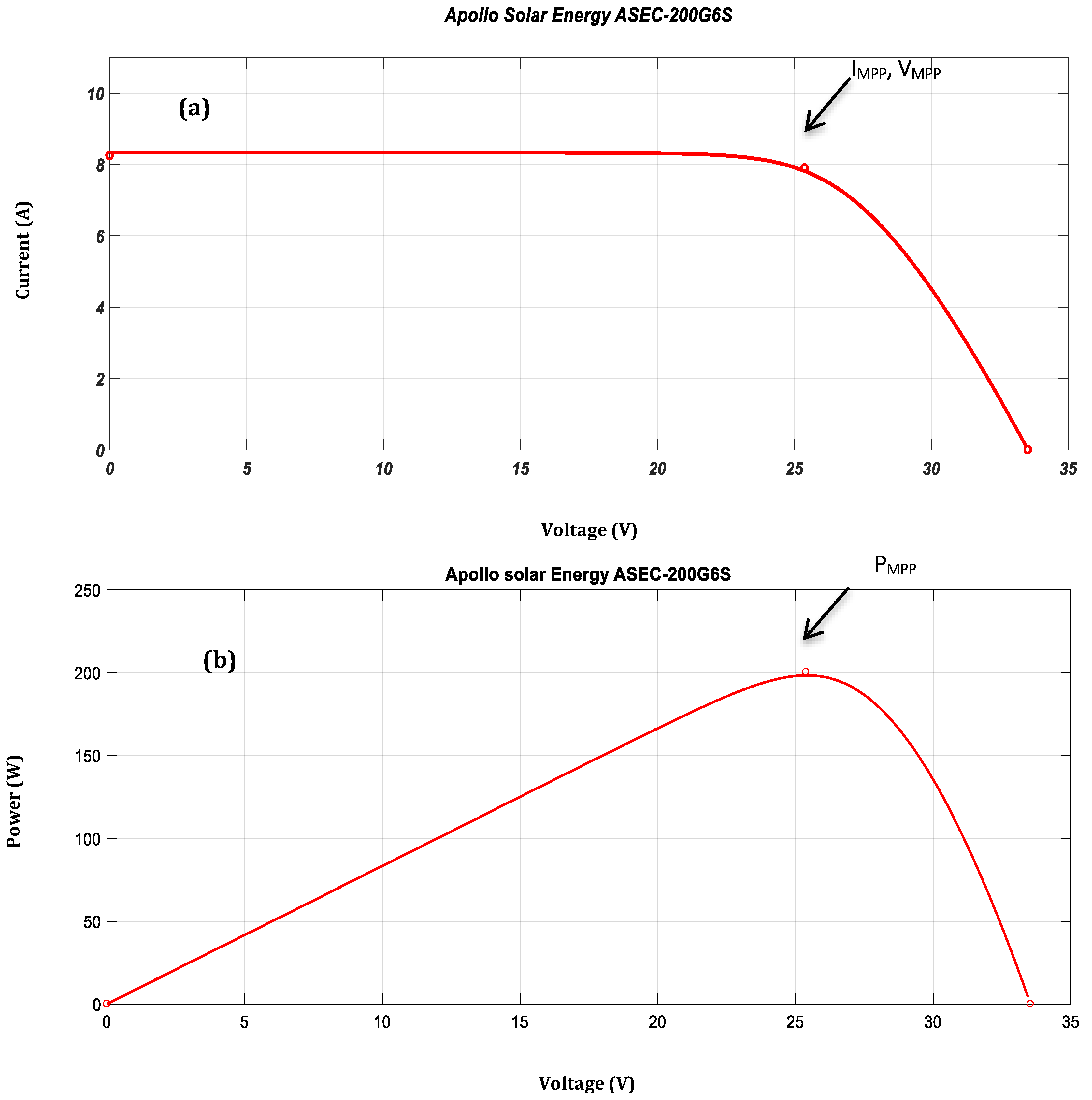
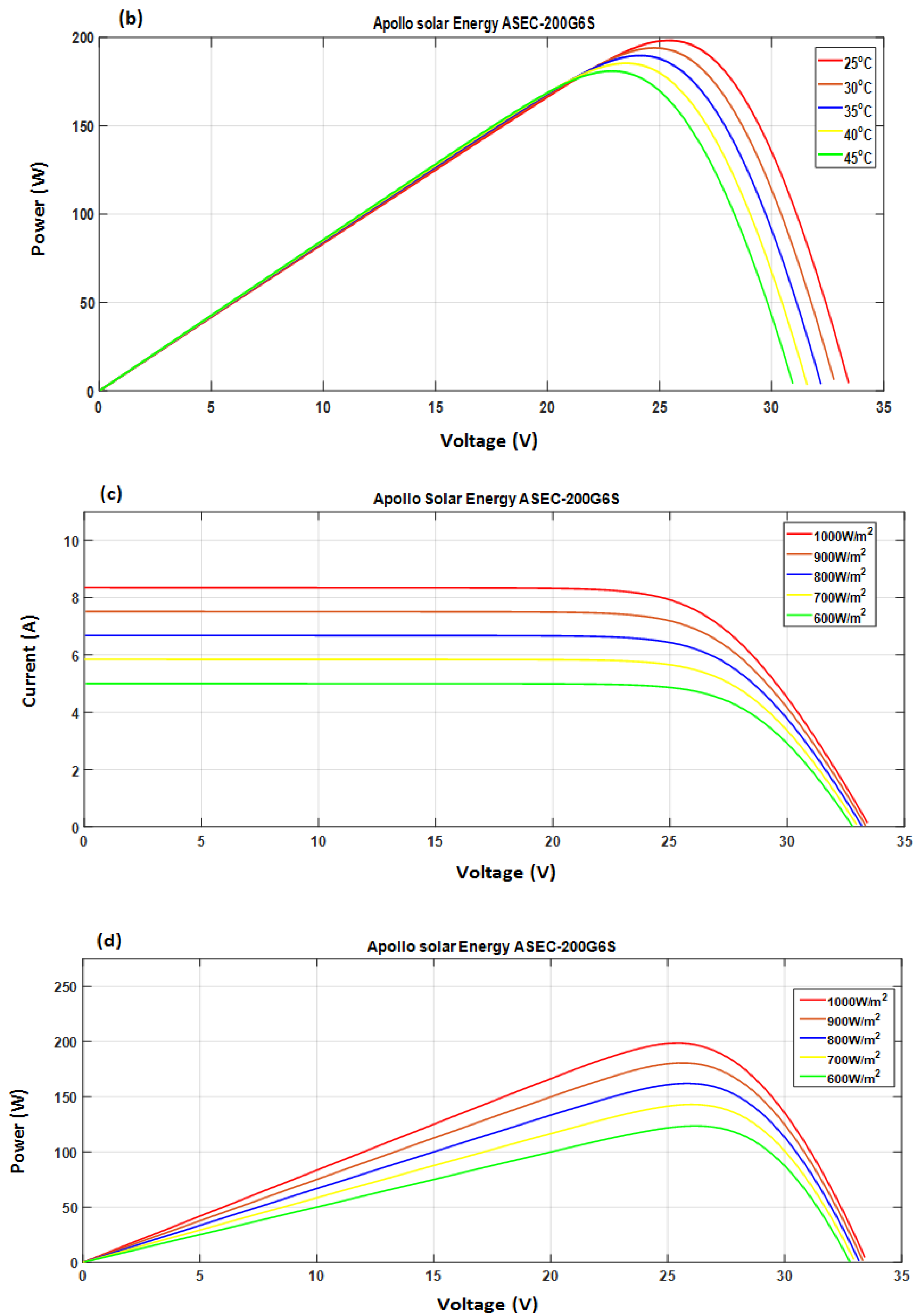
4.1. Modeling of a PV Panel

Figure 5 shows the MATLAB-SIMULINK block diagram of the PV panel [18] used in our protocol system.
For the modeling of the PV panel block, we chose the Apollo SOLAR ENERGY ASEC-200G6S module available in the Simulink-Matlab library. This module is made up of 54 monocrystalline silicon cells with a maximum power of 200 W. Table 2 contains the parameters that characterize the module under standard conditions (level of solar radiation: G = 1000 W/m2, cell temperature: 25 °C, AM = 1.5).
Current-voltage (I-V) curve and power-voltage curve (P-V) of the PV module (T = 25 °C, G = 1000 W/m2):
Current-voltage curve (I-V) and power-voltage curve (P-V) of the PV module (T = 25 °C, G = 1000 W/m2) exhibit a nonlinear relationship with the temperature and irradiance. However, on this characteristic curve (Figure 6a,b), there is a unique point where the entire system can work with maximum efficiency. This point is called the maximum power point M.P.P. It requires calculations, tracking, and control techniques to ensure the PV system is operating at this unique point to achieve the most incredible power harvest. Tracking of the maximum power point (MPPT) is a way to extract the maximum energy from the photovoltaic panels at different irradiance levels. Figure 6 shows the characteristic I-V and P-V of the PV module for a temperature T = 25 °C and a solar radiation G = 1000 W/m2. We found the short circuit current or the maximum current at zero voltage ISC = 8.24 A and the open circuit voltage or the maximum voltage at zero current VOC = 33.53 V. This result explains the 54 cells that make up the photovoltaic panel. The power delivered by the PV panels depends on the operating point of the generator. The max point represents the maximum power delivered by the generator (PMPP = IMPP*VMPP, where, VMPP s to the voltage to the maximum power supplied by PMPP, and the IMPP corresponds to the current to the maximum power supplied PMPP).
Influence of temperature and Irradiance on I-V and P-V characteristics:
The temperature is a very important parameter in the operation of a PV module because of the temperature sensitivity of the electrical properties of the semiconductor. The characteristic I-V and P-V of a PV module according to the temperature under constant solar radiation (1000 W/m2) is represented in Figure 7a,b. We note that this characteristic I-V varies only slightly when the temperature varies, which means that the temperature has an effect over a long period of operation. It shows that the short-circuit current (I.S.C.) increases slightly with the temperature. It is thus observed that the influence of the temperature on (I.S.C.) and the maximum power current can be negligible and that the maximum power (PMPP) of the PV module undergoes a decrease when the temperature increases.
Figure 7c,d shows the I-V and P-V characteristics of the PV module for different irradiance levels by fixing the temperature value at 25 °C. We noticed that the I-V characteristics undergo a change with the irradiance and that the short-circuit current (I.S.C.) was directly proportional to the incident light intensity according to Equation (3). On the other hand, the increase in illumination causes a slight increase in the open-circuit voltage (V.O.C.). We deduced that the cell could provide an almost correct voltage, even in low light. This implies that the optimal power of the cell (Pmax) is practically proportional to the illumination, and the maximum power points are at approximately the same voltage.
I_SCI_ph = α (T) × G × S
where G is the solar radiation in W/m2, S is the surface of the cell in m2, α(T) is a coefficient depending weakly on the temperature; it is expressed in A/W (in our case α = 0.136/°K). Therefore, we can conclude that the shift of the I-V curves toward the increasing values allows the module to produce greater electrical power. This explains that solar irradiations lead to an increase in power corresponding to the maximum power points (PMPP).
The influence of temperature is smaller compared to that of solar irradiance, but it is no longer negligible on the I-V characteristic of a PV module. For a change in the temperature value, we can see that the voltage variation changes much more than that of the current, which varies very slightly.

4.2. Command of the Servomotor for Position-Controlled by P.W.M.

The block diagram used in modeling the D.C. motor is shown in Figure 8. For our simulation, we have represented the equation system of a D.C. motor in this block diagram. The input parameters are the supply voltage (Ua) and the resistive torque (Cr). The accessible output parameters are the motor current (ia), the motor torque (Ce), and the rotation speed (Wm) by calculating the motor angle θ through integrating of the Wm.
To facilitate the creation of our servo motor models in the Simulink environment, we used SimScape (physical systems simulation), which is an effective method for developing the mathematical model of the physical system by creating a multi-domain diagram based on physical connections. In addition, SimScape products allowed us to vary the system design without determining and implementing system-level equations. Figure 9 shows the block diagram we used in the SimScape simulation.
Figure 10 shows the simulation results of our servomotor, taking as input the set point (90°) and using the gains of the following P.I.D. controller: Kp = 100, Ki = 1, and Kd = 0 to drive the motor at the desired angle. The step response given in Figure 10 shows that the servomotor reaches its reference position at the angle of 90° for a response time that is less than 1 s. We have chosen a 12 v D.C. motor for our design. The parameters and the simulation results of this motor and the chopper, such as the temporal variation of the speed, current, and torque, the voltage at the chopper output, and the step response of a position-controlled servomotor, will be published soon in another article.

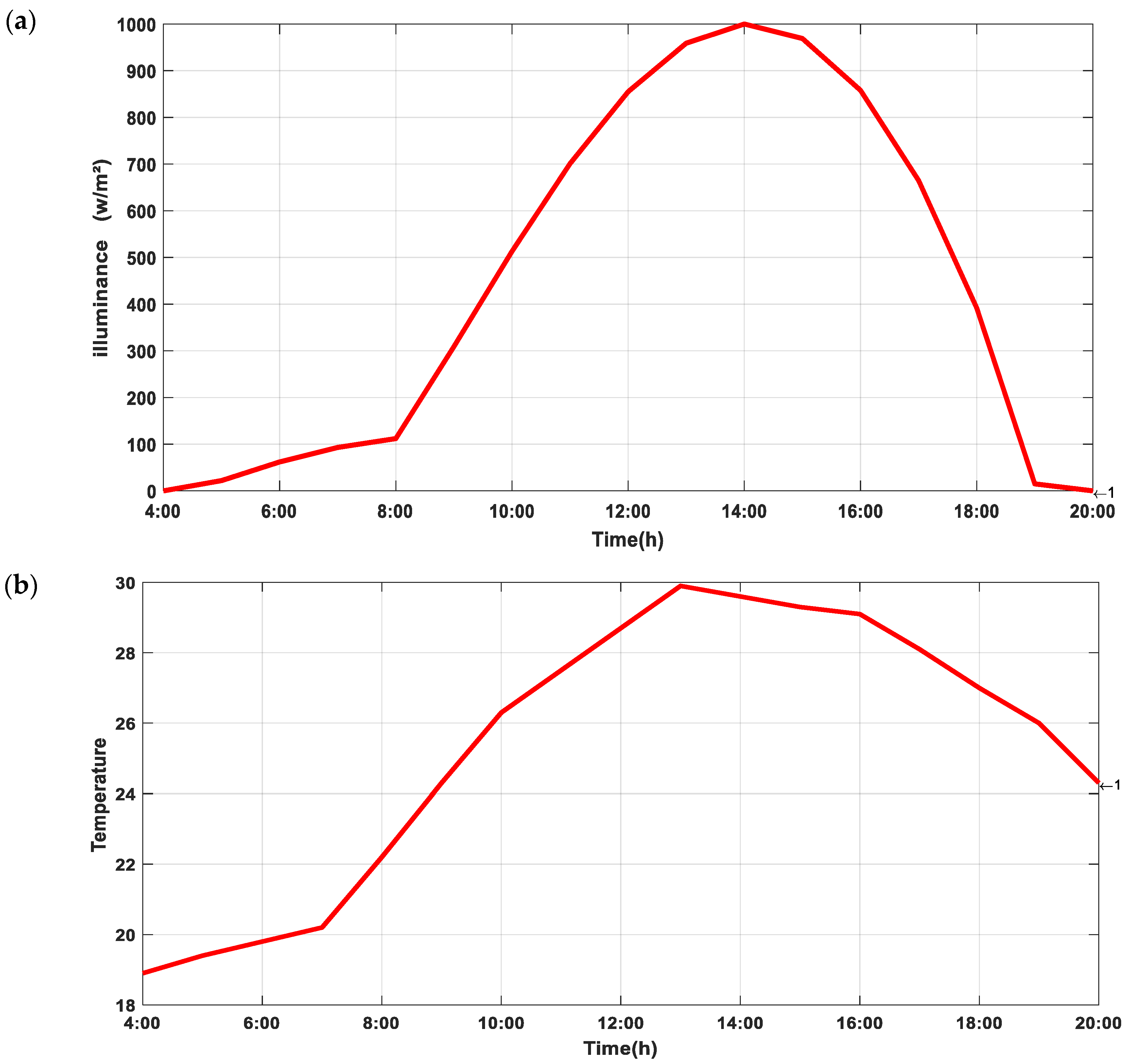
4.3. Simulation of the Sun

Single-axis solar tracker systems rotate on an axis to track the sun, facing east in the morning and west in the afternoon. This type of follower needs seasonal tilt angle adjustment.
The meteorological parameters such as temperature and sunshine of the city of Khemis Miliana were extracted using a PV-system site in real-time and the data of the meteorological station from the university.
The temporal variation of different sun parameters like sun radiation, temperature, and sun angle θ are shown in Figure 11a,b and Figure 12. The simulation was carried out for 16 h from 4:00 a.m. to 8:00 p.m. in May. Where the value of the irradiance used in the study area during the days of the simulation was:
-
Equal to 0 from 00:45 a.m. to 4:45 a.m. and from 8:45 p.m. to 11:45 p.m.;
-
Starts increasing by 11 and 1030 from 5:45 a.m. to 13:45 p.m., then decreases from 1030 to 8 from 2:45 p.m. to 7:45 p.m.
As long as the light reappears each morning at sunrise and the temperature rises and begins to disappear at sunset, there is a variation in irradiance during the day, regardless of the season. It can be seen that the irradiance reaches its maximum value at 2:00 p.m. and decreases at sunset when it is colder than during the day. Global irradiation corresponds to the solar energy received in one day; this irradiation is linked to irradiance. It is noted that the temperature and the irradiance vary during the year gradually; they increase from winter until summer and decrease from summer until winter. This is explained by the height of the sun, which varies according to the seasons: the sun is higher at noon in a summer sky than in a winter sky.
The position of the sun is given by the zenith angle (γs) and the azimuth (αs). The zenith angle is the angle between the local vertical and the line that connects the observer to the sun. The sun’s azimuth is the deviation of the sun’s position from the south. The zenith and azimuth depend on the local time of day (t), the day of the year (d), and the latitude (λ) of the observer (h) [4]. Figure 12 shows that the sun’s angle is equal to 90° almost at noon, so the tracker is perpendicular. At 180° at 8:00 p.m., the tracker is at a horizontal position and returns to its starting position.

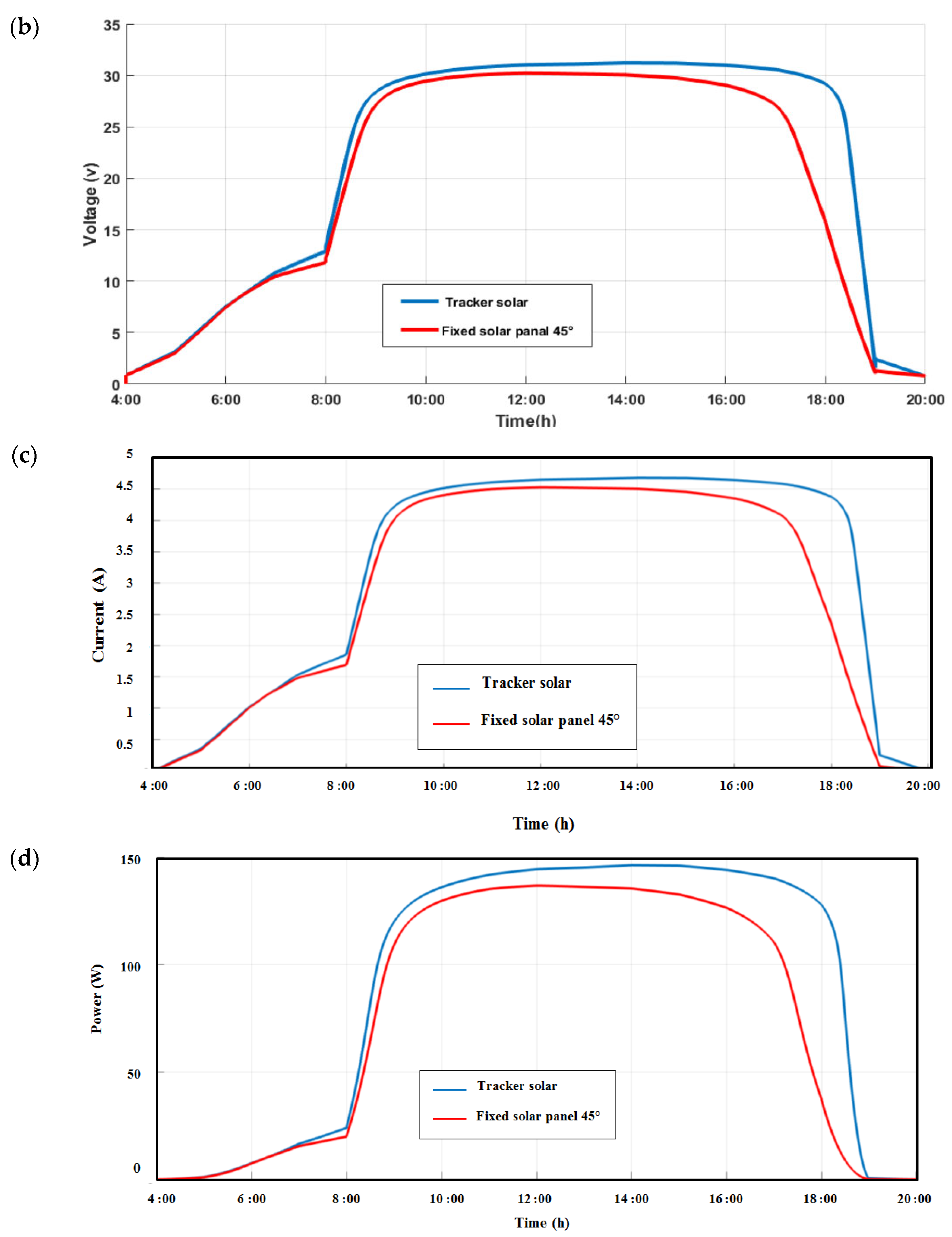
4.4. Tests of the Tracker

After receiving a quantity of light using a lamp, the prototype tracker starts tracking the solar radiation (Figure 13a). Figure 13b shows that the tracker is in the perpendicular position (90° almost at noon).
To validate our results, we performed two tests on the prototype of the single-axis solar tracker: the photovoltaic module connected to the prototype of the tracker and checking if it is in its fixed position. Figure 14a,b show the variation of the motor angle (Tracker angle) with respect to the sun angle for the two tests. It can be seen that the solar tracker reaches its reference position (sun angle) in a time of response of less than a second.
Several studies have analyzed the efficiency of energy production using single-axis trackers compared to fixed panels [35,36,37,38]. BAHRAMI et al. [37] determined that the increase in solar production of a PV plant with single-axis trackers compared to a fixed-panel system is around 17.22–31.23% [39,40,41]. That fluctuation in energy production can be reduced depending on the tracker distribution in the PV plant [42,43,44].
To validate our design, we compared the motor angle and the sun angle over an entire day if the panel is fixed and if the panel is attached to our prototype single-axis tracker. As the sun begins to shine at 5:00 a.m., our system records data until sunset. Figure 15 shows that the solar tracker device maximizes the sun’s irradiance by keeping the solar module’s active surface vertical at the sun’s angle. From noon until sunset, we find that the fixed panel loses a large amount of solar radiation during the day.
Figure 16a–d show the values variation of illuminance, voltage, current, and power of a PV module for two cases (with and without the tracker), which are compared for the period spanning from sunrise to sunset. When the curves are examined between 8:00 a.m. and 11:00 a.m., the voltage, current, and power values are a little close for the two cases. On the other hand, in the afternoon, between 12:00 p.m. and 7:00 a.m., we observed a large difference in the quantity of the voltage, current, and power produced. We concluded that a fixed panel’s energy loss was recorded from noon until sunset.

5. Conclusions

The question of sizing and of optimizing the efficiency of the PV solar panel is always a crucial step during their installation. Photovoltaic tracker systems represent an important area in which a significant amount of research has been carried out. However, the field itself is so vast that there is always room for innovation or improvement. This has prompted us to study this field, enabling the development of PV tracking systems to increase the efficiency of PV modules and, therefore, higher electrical energy production. We have optimized the production of a photovoltaic solar system by using a solar tracker system that we designed on our own. The various elements of our solar tracker were exposed, and we noticed that the part devoted to the control and the electronic command of the maneuvers of this system was the most important. Thanks to the choice of the Arduino board, and the control program that we developed, we could design a complete prototype system by our own configuration, which showed better sensitivity in tracking the trajectory of the sun. The use of an LDR system has enabled us to find a completely autonomous solution that is easy to set up and brings an interesting energy gain, especially during the less sunny hours of the day. The test of the instantaneous energy production through the PV panel that we used showed that following the sun would benefit the future photovoltaic installations that our sun tracking system will support. We can conclude that the photovoltaic tracker systems with appropriate control systems can be considered an important factor in increasing the electrical power by 22 to 56%, compared to the fixed photovoltaic system. This research field is developing very fast; hence, many types of research are ongoing, such as artificial neural networks and fuzzy logic. These tools are used in all fields where fuzzy logic controllers are used for tracking the maximum power point in a photovoltaic system [45].
Currently, cascade control algorithms are used for high-concentration photovoltaics, capable of achieving a sun tracking error of one minute. Scientists and researchers are working on optimizing energy extraction. In doing so, an approach based on deep learning, low-cost open hardware, and computer vision has been developed to reduce the limitations regarding costs and operational issues [46]. Despite many developments, this area still faces some hurdles. Therefore, more work regarding operational efficiency, cost-effectiveness, and feasibility is required. In future perspectives, we plan to develop our tracking system using these new techniques, starting by implementing a manual mode to the automatic control system, as well as a remote access mode and control of PV production of this system.

Author Contributions

Conceptualization, F.Z.B.; Data curation, B.A. and F.Z.B.; Investigation, A.L., T.C.M. and S.V.H.; Project administration, G.S.; Resources, K.A.; Supervision, M.S.R.; Writing—original draft, F.E.Ț. and F.Z.B. All authors have read and agreed to the published version of the manuscript.

Funding

This work was supported by a grant from the Romanian Ministry of Education and Research, CCCDI-UEFISCDI, project number PN-III-P2-2.1-PED-2019-1294, within PNCDI III. 598. This paper was partially supported by the UEFISCDI Romania and MCI through BEIA projects, 599 AISTOR, FinSESco, CREATE, Hydro3D, EREMI, SOLID-B5G, NGI-UAV-AGRO, U-GARDEN and 600 by the European Union’s Horizon 2020 research and innovation program under grant agreements No. 601 872172 (TESTBED2) and No. 777996 (SealedGRID). This work is supported by Ministry of Research, Innovation, Digitization from Romania by the National Plan of R & D, Project PN 19 11, Subprogram 1.1. Institutional performance-Projects to finance excellence in RDI, Contract No. 19PFE/30.12.2021 and a grant of the National Center for Hydrogen and Fuel Cells (CNHPC)—Installations and Special Objectives of National Interest (IOSIN).

Institutional Review Board Statement

Romanian Ministry of Education and Research, CCCDI-UEFISCDI, project number PN-III-P2-2.1-PED-2019-1294.

Acknowledgments

This research was partially technically supported by the research laboratory of the University of Khemis Miliana. The authors thank Meriem Saber, a researcher at the “renewable energy development center”, for her help in this research.

Conflicts of Interest

The authors declare no conflict of interest.

References

  1. Hua, Z.; Ma, C.; Lian, J.; Pang, X.; Yang, W. Optimal capacity allocation of multiple solar trackers and storage capacity for utility-scale photovoltaic plants considering output characteristics and complementary demand. Appl. Energy 2019, 238, 721–733. [Google Scholar] [CrossRef]
  2. Gómez-Uceda, F.J.; Moreno-Garcia, I.M.; Jiménez-Martínez, J.M.; López-Luque, R.; Fernández-Ahumada, L.M. Analysis of the Influence of Terrain Orientation on the Design of PV Facilities with Single-Axis Trackers. Appl. Sci. 2020, 10, 8531. [Google Scholar] [CrossRef]
  3. Chong, K.; Wong, C. General Formula for on-axis sun-tracking system and its application in improving tracking accuracy of solar collector. Sol. Energy 2009, 83, 298–305. [Google Scholar] [CrossRef]
  4. Ferroudji, F. Conception et Optimisation en Dynamique Forcée D’un Nouveau Prototype de Système de Suiveur Solaire à Deux axes. Ph.D. Thesis, University of Batna, Batna, Algeria, 2015. [Google Scholar]
  5. Abu-Khadera, M.; Badranb, O.; Abdallah, S. Evaluating multi-axes sun-tracking system at different modes of operation in Jordan. Renew. Sustain. Energy Rev. 2008, 12, 864–873. [Google Scholar] [CrossRef]
  6. Available online: http://shodh.inflibnet.ac.in/bitstream/123456789/4251/3/03_liteature%20review.pdf (accessed on 22 August 2022).
  7. Alexandru, C.; Pozna, C. Different tracking strategies for optimizing the energetic efficiency of a photovoltaic system. In Proceedings of the 2008 IEEE International Conference on Automation, Quality and Testing, Robotics, Cluj-Napoca, Romania, 22–25 May 2008; Volume 3, pp. 434–439. [Google Scholar]
  8. Natarajan, S.K.; Thampi, V.; Shaw, R.; Kumar, V.S.; Nandu, R.S.; Jayan, V.; Rajagopalan, N.; Kandasamy, R.K. Experimental analysis of a two axis tracking system for solar parabolic dish collector. Int. J. Energy Res. 2019, 43, 1012–1018. [Google Scholar] [CrossRef]
  9. AL-Rousan, N.; Mat Isa, N.A.; Mat Desa, M.K. Correlation analysis and MLP/CMLP for optimum variables to predict orientation and tilt angles in intelligent solar tracking systems. Int. J. Energy Res. 2021, 45, 453–477. [Google Scholar] [CrossRef]
  10. Farrar-Foley, N.; Rongione, N.A.; Wu, H.; Lavine, A.S.; Hu, Y. Total solar spectrum energy converter with integrated photovoltaics, thermoelectrics, and thermal energy storage: System modeling and design. Int. J. Energy Res. 2021, 46, 5731–5744. [Google Scholar] [CrossRef]
  11. El Moubarak Bouzid, A.; Mohammed, A. Dimensionnement D’un Système Photovoltaïque Pour L’alimentation D’une Ferme Étude de L’onduleur Triphasé Lié à Cette Application. Engineer Thesis, University of Oran, Es Senia, Algeria, 2008. [Google Scholar]
  12. Hafez, A.Z.; Yousef, A.M.; Harag, N.M. Solar tracking systems: Technologies and trackers drive types. A review. Renew. Sustain. Energy Rev. 2018, 91, 754–782. [Google Scholar] [CrossRef]
  13. Merlaud, A.; De Mazière, M.; Hermans, C.; Cornet, A. Equations for Solar Tracking. Sensors 2012, 12, 4074–4090. [Google Scholar] [CrossRef]
  14. Ruelas, J.; Muñoz, F.; Lucero, B.; Palomares, J. PV Tracking Design Methodology Based on an Orientation Efficiency Chart. Appl. Sci. 2019, 9, 894. [Google Scholar] [CrossRef] [Green Version]
  15. Visconti, P.; Costantini, P.; Orlando, C.; Lay-Ekuakille, A.; Cavalera, G. Software solution implemented on hardware system to manage and drive multiple bi-axial solar trackers by PC in photovoltaic solar plants. Measurement 2015, 76, 80–92. [Google Scholar] [CrossRef]
  16. Nsengiyumva, W.; Chen, S.G.; Hu, L.; Chen, X. Recent advancements and challenges in Solar Tracking Systems (S.T.S.): A review. Renew. Sustain. Energy Rev. 2018, 81, 250–279. [Google Scholar] [CrossRef]
  17. Awasthi, A.; Shukla, A.K.; Manohar S.R., M.; Dondariya, C.; Shukla, K.N.; Porwal, D.; Richhariya, G. Review on sun tracking technology in solar PV system. Energy Rep. 2020, 6, 392–405. [Google Scholar] [CrossRef]
  18. Ladmi, A.; Arbaoui, K. Modélisation et Optimisation des Performances D’un Suiveur Solaire. Master’s Thesis, Faculty of Sciences and Technology, University of Khemis Miliana, Khemis Miliana, Algeria, 2019. [Google Scholar]
  19. Hariri, N.G.; AlMutawa, M.A.; Osman, I.S.; AlMadani, I.K.; Almahdi, A.M.; Ali, S. Experimental Investigation of Azimuth- and Sensor-Based Control Strategies for a PV Solar Tracking Application. Appl. Sci. 2022, 12, 4758. [Google Scholar] [CrossRef]
  20. Alici, H.; Esenboga, B.; Oktem, I.; Demirdelen, T.; Tumay, M. Chapter 7: Designing and performance analysis of solar tracker system: A case st udy of Çukurova region. In Design, Analysis, and Applications of Renewable Energy Systems Advances in Nonlinear Dynamics and Chaos (ANDC); Academic Press: New York, NY, USA, 2021; pp. 165–184. [Google Scholar]
  21. Balabel, A.; Mahfouz, A.; Salem, F. Design and performance of Solar Tracking Photo-Voltaic system; Research and education. Int. J. Control Autom. Syst. 2013, 1, 49–55. [Google Scholar]
  22. Etude, K.I. Conception et Réalisation d’un Suiveur de Soleil. Master’s Thesis, University of Abou-Bekr Belkaid Tlemcen-Algeria, Chetouane, Algeria, 2018. [Google Scholar]
  23. Chin, C.S.; Babu, A.; McBride, W. Design, modeling and testing of a standalone single axis active solar tracker using MATLAB/Simulink. Renew. Energy 2011, 36, 3075–3090. [Google Scholar] [CrossRef]
  24. Mousazadeh, H.; Keyhani, A.; Javadi, A.; Mobli, H.; Abrinia, K.; Sharifi, A. A review of principle and sun-tracking methods for maximizing solar systems output. Renew. Sustain. Energy Rev. 2009, 13, 1800–1818. [Google Scholar] [CrossRef]
  25. Afarulrazi, B.A.; Utomo, W.M.; Liew, K.L.; Zarafi, M. Solar tracker robot using microcontroller. In Proceedings of the 2011 International Conference on Business, Engineering and Industrial Applications, Kuala Lumpur, Malaysia, 5–7 June 2011; pp. 47–50. [Google Scholar]
  26. Nuwayhid, R.Y.; Mrad, F.; Abu-Said, R. The realization of a simple solar tracking concentrator for university research applications. Renew. Energy 2001, 24, 207–222. [Google Scholar] [CrossRef]
  27. Le Moteur à Courant Continu: Principe, Astuces-Pratiques. 2015. Available online: https://www.astuces-pratiques.fr/electronique/le-moteur-a-courant-continu-principe (accessed on 22 August 2022).
  28. Eric, G. Le Servomoteur. 2011. Available online: http://ericaeromodelisme974.unblog.fr/2011/06/04/le-servomoteur (accessed on 22 August 2022).
  29. Rabeh, M.B.; Ayoub, D. Conception et Réalisation d’un Suiveur Solaire Bi-axial à Bas De capteurs de lumière. Master’s Thesis, University of Kasdi Merbah Ouargla, Ouargla, Algeria, 2016. [Google Scholar]
  30. Electrical Guide 360. D.C. Chopper or DC-to-DC Converter: Working & Its Function; Power Electronics: Valencia, Spain, 2021. [Google Scholar]
  31. Solar Angles & Tracking Systems. Photovoltaic Efficiency: Lesson 1, Fundamentals Article; Free STEM Curriculum for K-12. Available online: https://www.TeachEngineering.org (accessed on 22 August 2022).
  32. Telidjane, M. Modélisation des Panneaux Photovoltaïques et Adaptation de la Cyclostationarité pour le Diagnostic. Ph.D. Thesis, University of Lyon, Lyon, France, 13 July 2017. [Google Scholar]
  33. Marwan; Anshar, M. Controller Design for Solar Tracking System. In Proceedings of the International Conferences on Information System and Technology (CONRIST 2019), Yogyakarta, Indonesia, 5–6 December 2019; pp. 72–77. [Google Scholar] [CrossRef]
  34. Engr, F. How to Make a Solar Tracker Using Arduino, Arduino Solar Tracker System Its Circuit and Programming; Electronic Clinic: Wan Chai, Hong Kong, 2019. [Google Scholar]
  35. Aqib, M. Sun Tracking Solar Panel Using Arduino. Microcontroller-Projects. 2017. Available online: https://Circuitdigest.com (accessed on 22 August 2022).
  36. Necir, A.; Bouchaala, A.D.J. Conception et Réalisation d’un Suiveur du Soleil Commandé par une Carte Arduino. Master’s Thesis, University of El-Oued, El Oued, Algeria, 2018. [Google Scholar]
  37. Koussa, M.; Cheknane, A.; Hadji, S.; Haddadi, M.; Noureddine, S. Measured and modelled improvement in solar energy yield from flat plate photovoltaic systems utilizing different tracking systems and under a range of environmental conditions. Appl. Energy 2011, 88, 1756–1771. [Google Scholar] [CrossRef]
  38. Bahrami, A.; Okoye, C.O.; Atikol, U. The effect of latitude on the performance of di erent solar trackers in Europe and Africa. Appl. Energy 2016, 177, 896–906. [Google Scholar] [CrossRef]
  39. Abdallah, S.; Nijmeh, S. Two axes sun tracking system with PLC control. Energy Convers. Manag. 2004, 45, 1931–1939. [Google Scholar] [CrossRef]
  40. Antonanzas, J.; Urraca, R.; Martinez-de-Pison, F.J.; Antonanzas, F. Optimal solar tracking strategy to increase irradiance in the plane of array under cloudy conditions: A study across Europe. Sol. Energy 2018, 163, 122–130. [Google Scholar] [CrossRef]
  41. Batayneh, W.; Bataineh, A.; Soliman, I.; Hafees, S. Investigation of a single-axis discrete solar tracking system for reduced actuations and maximum energy collection. Autom. Constr. 2019, 98, 102–109. [Google Scholar] [CrossRef]
  42. Manoel Henriques de Sa, C.; Chigueru, T. npTrack: A n-Position Single Axis Solar Tracker Model for Optimized Energy Collection. Energies 2021, 14, 925. [Google Scholar]
  43. Seme, S.; Stumberger, B.; Hadziselimovic, M.; Sredensek, K. Solar Photovoltaic Tracking Systems for Electricity Generation: A Review. Energies 2020, 13, 4224. [Google Scholar] [CrossRef]
  44. Kuttybay, N.; Saymbetov, A.; Mekhilef, S.; Nurgaliyev, M.; Tukymbekov, D.; Dosymbetova, G.; Meiirkhanov, A.; Svanbayev, Y. Optimized Single-Axis Schedule Solar Tracker in Different Weather Conditions. Energies 2020, 13, 5226. [Google Scholar] [CrossRef]
  45. Farajdadian, S.; Hosseini, S.M.H. Conception d’un contrôleur flou optimal pour obtenir une puissance maximale dans un système de production d’énergie solaire. Solar Energy 2019, 182, 161–178. [Google Scholar] [CrossRef]
  46. Onyeka Okoye, C.; Bahrami, A.; Atikol, U. Evaluating the solar resource potential on different tracking surfaces in Nigeria. Renew. Sustain. Energy Rev. 2018, 81 Pt 1, 1569–1581. [Google Scholar] [CrossRef]
Figure 1. Block diagram of a single-axis tracker.
Applsci 12 09682 g001
Figure 2. Block diagram of (a) effective radiation quantity; (b) modeling of the sun.
Applsci 12 09682 g002
Figure 3. (a) Servo motor electrical diagram; (b) Position of the servo motor compared with the Arduino card.
Applsci 12 09682 g003
Figure 4. Block diagram used during simulation by ISIS.
Applsci 12 09682 g004
Figure 5. MATLAB-SIMULINK block diagram of a PV panel.
Applsci 12 09682 g005
Figure 6. Characteristic curves of the PV module: (a) Current-voltage I-V curve, (b) Power-voltage curve P-V.
Applsci 12 09682 g006
Figure 7. Influence of the variation in the temperature value on (a) characteristic I-V; (b) characteristic P-V. Influence of variation in the irradiance value on (c) characteristic I-V; (d) characteristic P-V.
Applsci 12 09682 g007aApplsci 12 09682 g007b
Figure 8. Simulink block model of the servomotor.
Applsci 12 09682 g008
Figure 9. Block model of a voltage-fed motor using SimScape’s Simulink.
Applsci 12 09682 g009
Figure 10. Step responses of a position-control servo motor.
Applsci 12 09682 g010
Figure 11. (a) Temporal variation of irradiance during a day. (b) Temporal variation of temperature during a day.
Applsci 12 09682 g011
Figure 12. Temporal variation of the sun angle during a day.
Applsci 12 09682 g012
Figure 13. Tests of the tracker position: (a) start position of the solar tracker realized to start tracking of the light. (b) Perpendicular position (90°) of the solar tracker.
Applsci 12 09682 g013
Figure 14. Variation of the motor angle with respect to the sun’s angle: (a) for test 1. (b): for test 2.
Applsci 12 09682 g014
Figure 15. Comparison between sun angle and sun tracker angle.
Applsci 12 09682 g015
Figure 16. Values of (a) solar radiation, (b) voltage, (c) current, and (d) power produced by a PV panel bound with a solar tracker compared to a fixed PV panel.
Applsci 12 09682 g016aApplsci 12 09682 g016b
Table 1. Characteristic parameters of the servomotor used in the construction of the prototype of the single-axis tracker.
Parameters/CharacteristicsValues
Weight14.6 g
Torque2.5 kg.cm (4.8 v) 2.8 kg.cm (6.0 v)
Operating speedOperating: 0.11 s/60 degree (4.8 v) 0.09 s/60 degree (6.0 v)
Size22.5 × 12.2 × 35 mm
Table 2. Characteristics of the APOLLO SOLAR ENERGY ASEC-200G6S module.
Parameters/CharacteristicsValues
Maximum power   P mpp [ W ] 200
Voltage of the maximum power   V mpp [ V ] 25.38
Current of the maximum power   I mpp   [ A ] 7.89
Open-circuit voltage     V .O.C.   [ V ] 33.53
Short-circuit current     I SC [ A ] 8.24
Temperature   Coefficient     K i ( I SC )   [%/K]0.136
Temperature   Coefficient     K i ( V OC )   [%/K]−0.37101
Temperature   Coefficient     K i ( P mpp )   [%/K]−0.47
Length x width x height [mm]1660 × 990 × 50
Number of cells54
Cell size [mm]156 × 156
Cell materialMonocrystalline Si stalling
Publisher’s Note: MDPI stays neutral with regard to jurisdictional claims in published maps and institutional affiliations.

