Abstract
This paper quickly calculated the design variables to satisfy the strength and stability conditions, the dominant design verification conditions of the composite wing structure, through a genetic algorithm. It developed a variable stiffness stacking optimization process applicable to aircraft wing structure design. We proposed a laminate parameter-based optimization strategy that considers the stiffness characteristics of the two-dimensional elements used as design variables. Compared with the optimization results obtained using continuous stiffness optimization as an optimization process function of laminate sequences with genetic algorithms, we obtained a reasonable stiffness distribution while complying with critical guidelines related to individual composite layup designs. The results of the stiffness optimization design were implemented as a finite element model, and the results were verified through NASTRAN. We demonstrated the functionality of the stiffness optimization process by obtaining results satisfying the set response conditions, i.e., strength and stability, in many design areas of the wing.
1. Introduction
Worldwide, unmanned aerial vehicles are drawing significant attention in the military/private sector to carry out reconnaissance, tracking, surveillance, communication broadcasting, and attacks. Until now, missions have been achieved mainly by human-crewed aircraft, but the same mission can be achieved, or more dangerous missions can be performed through unmanned aerial vehicles. In addition, unmanned aerial vehicles have the advantage of being more economical than human-crewed aircraft. In order to increase economic efficiency and practicality in aircraft design, the mass of the aircraft plays a decisive role. Composite materials are essential for mass reduction and have excellent material properties. Composite material has excellent stiffness and a significantly lower density than the weight generated compared to the metal material. In addition, the orthogonal rigidity properties of a single composite layer may be selectively applied, and the rigidity may be adjusted to react better to load transfer. As design, analysis, and manufacturing technologies develop, the frequency of applying composite materials to structures that deliver aircraft loads rapidly increases.
In a related study, Mamalis et al. [1] presented the energy absorption capacity of composite materials and studied more practical aspects of collision characteristics. Koohi et al. [2] developed a modified 1-D structural dynamics model for the aeroelasticity analysis of composite wings subjected to large deformations and performed deformation behavior. Vasiliev et al. [3] proposed an actual method for interpretation after combining anisotropic beams with composite beams with controlled characteristics. Farsadi et al. [4] studied the effects of the fiber and torsion angles of CAS lamination composition on nonlinear aeroelasticity margins and marginal behavior. Jiang et al. [5] studied the aerodynamic properties of synthetic laminated trapezoidal panels considering the compressibility of supersonic airflow and shock waves and developed an effective finite element method. Gu et al. [6] analyzed the simplified finite element model of a composite wing box and the analysis method for the dimensional determination of structural members. Lee et al. [7] studied methods and procedures for the structural design of improved unmanned air vehicles to improve long-term flight and applied them to the entire wings of composite materials for room temperature curing. Kim et al. [8] performed a static aeroelasticity analysis capable of calculating the air force for the deformed shape of a composite wing. Han et al. [9] performed load analysis on the wings of the composite material SUNMIK aircraft under development. Zhao et al. [10] proposed a two-stage optimization in which the system is adjusted according to structural deformation for composite wings, and the layout meets the constraints at the subsystem level. Mastroddi et al. [11] developed an MDO approach based on integrated modeling to perform optimization using shape variables and standard structure design variables. Haddapour et al. [12] optimized composite material wings using a linear horizontal change in the fiber direction resulting from a variable strength structure. Jing et al. [13] suggested high efficiency and the possibility of a large-scale composite material structure design by improving the variables handled separately and the constraints imposed in each step and expanding them from individual panels to the entire structure. Chintapali et al. [14] optimized composite wings’ reinforced panel structure design that met the constraints by using lamination thickness and various stringer spacing. However, while optimizing, research was conducted for a more efficient approach due to increased design time and cost due to computational complexity and many design variables. Wan et al. [15] studied wing optimization using an electron/sensitivity-based mixing algorithm to minimize the structural load of wings using blade lamination thickness as a design variable. Kameyama et al. [16] studied the effect of laminated shape on the vibration and dispersion characteristics of composite wings using genetic algorithms. Seesta et al. [17] studied the effect of wing box design optimization problems on optimal design using a guide-based design methodology and a genetic algorithm. Fan et al. [18] optimized the stacking order of composite material structures using ply-drops based on genetic algorithms to increase the efficiency between symmetrical and balanced structures and lower the structure weight. Kim et al. [19] applied genetic algorithm techniques and branching methods to minimize the wing deformation energy and improve the wing’s structural safety under wind gusts. Kang et al. [20] conducted movement analysis of a composite material structure, which gets compressive load and optimized design with minimum load and breaking strength using a finite element program and parallelization genetic algorithms. Yoon et al. [21] performed an optimization design between multiple fields at the primary stage, applied genetic algorithms to optimization, and used gradient methods to non-planar shapes to compare and analyze efficiency. Lim et al. [22] performed optimization to find an accurate solution to the aircraft’s performance and structure and designed using PBLI, a genetic algorithm. Cho et al. [23] investigated various stacked structures that were insufficient in existing optimization techniques by applying genetic algorithms to rigid and weight optimization designs. Kim et al. [24] demonstrated that the improvement of genetic algorithms and the optimization of applying genetic algorithms to aerodynamic forms of 2-D/3-D wings are similar to traditional design methods. Mahfoud et al. [25] presented a genetic algorithm for adjusting optimal PID parameters in DTC to control DFIM using objective functions such as integral square error, integral time absolute error (ITAE), and integral absolute error. Sitek et al. [26] proposed a formal model of constraints and questions about extended vehicle routing problems for drones, including a dynamic selection of drone take-off points, two-way delivery (delivery and pickup), various types of delivery, delivery allocation to drones, drone allocation to vehicles, and optimal drone number selection. Junqueira et al. [27] described a simulation optimization methodology that combines simulation, genetic algorithms, and new solution representations to design an integrated plan for container relocation in a port yard and a storage plan problem to unload ships through the port. Finally, Chen et al. [28] used genetic algorithms and discrete particle cluster optimization algorithms to manage the complexity of the problem, calculate feasible and quasi-optimal trajectories for mobile sensors, and determine the demand for movement between nodes. Cheng et al. [29] described parametric modeling and design sensitivity analyses performed on hat stiffener elements for single- and multiple-hat-stiffened panels using parametrically defined scripting finite element analysis (FEA) models and an idealized analytical solution. Schlothauer et al. [30] optimized a UAV wing structure that carries more than 100 times its weight and was developed and tested to validate the design approach and demonstrate load carrying ability and manufacturing quality. Sohst et al. [31] conducted non-linear aeroelastic analyses using multi-fidelity tools to assess whether geometric non-linearities affected the optimized designs. The wing structure of the reconnaissance UAV is a thin and long shape, as it increases the duration of flying time. To maximize the efficiency of mission performance, the duration of flight in the mission area should be much longer than that of manned aircraft. Reducing drag and improving productivity should also be considered a shape suitable for surveillance reconnaissance and long-term flight. However, all shapes must be applied, and the fabrication process of the structure requires considerable manufacturing know-how, and it is difficult to ensure the reliability of the structure. In addition, interference between the outer skin and the inner structure should be overcome, and a detailed optimal stacking design is required for each wing part.
This paper uses genetic algorithms to consider the characteristics of thin and high aspect ratio wing structures and to achieve mass optimization. It provides a framework for a method for finding optimal stiffness or laminate sequence distribution. Through genetic algorithms, design variables are calculated to quickly satisfy the dominant design conditions of composite wing structures and strength and stability conditions through variable lamination. The stiffness change should be performed directly when changing the fiber angle or thickness within the part. In addition, it intends to develop a numerical analysis that can be concerned with responses to static strength and stability in the design of the UAV wings and is an optimization framework of variable stiffness. Finally, the stiffness optimization design results obtained through genetic algorithms are implemented as finite element models, and the results of finite element analysis are verified to satisfy the design constraints using NASTRAN, a commercial structural analysis program.
2. Theory for UAV’s Wing Structure Optimization
2.1. Principle of Genetic Algorithm
Genetic algorithms apply the laws of the natural world in which individuals with solid viability evolve into superior offspring by adapting to the natural world based on genetics and the principle of biological evolution. Conventional optimization methods use derivatives and methods of sequentially searching for objective functions in limited space and constraints or selecting a starting point to start the search. Therefore, although it was effective in a narrow area, there is a limit to exerting outstanding performance in a wide area. The genetic algorithm can solve the optimization problem because it does not use the objective function’s differential concept and performs probability and directional searches.
As shown in Figure 1, the genetic algorithm has a population composed of an array of binary numbers and performs optimization through the evolution process of selection, crossover, and mutation in the order of biological evolution. As the object evolves into the next generation, it transmits highly compatible genetic characteristics to the next generation. Crossover is the exchange of information by exchanging some of the information from the selected chromosomes with each other. Through this process, chromosomes are allowed to come close to the objective function by stochastic selection. In addition, a rapid convergence speed can reduce the time of analysis. Finally, mutations are the process of obtaining information that cannot be obtained through selection and crossover, which improves the convergence of high conformity. This is because the mutation process at random probabilities performs typical exploratory effects. Moreover, intersecting and mutant operators increase the group’s diversity to satisfy the optimization objective function, resulting in classic optimization and differentiation.
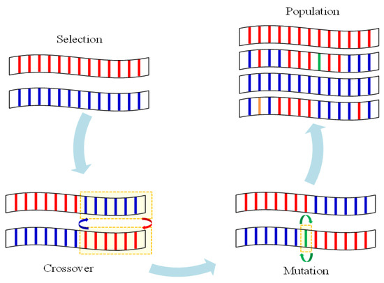
Figure 1.
General operation of the genetic algorithm.
2.2. Operator of Genetic Algorithm
The general genetic algorithm contains three operators: selection, crossover, and mutation. The selection operator selects chromosomes from the object group for reproduction, as shown in Figure 2. The chromosomes selected are based on their suitability, and higher suitability results in a large group of fit individuals, and a lower fit gives them a long evolutionary time. Furthermore, the selection aims to reproduce objects close to the fitted values, so the fitted values should be selected following the change and balance. Finally, the crossover operator produces two offspring by exchanging some of the before and after arrays of random locations in the selected chromosome.
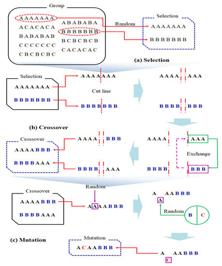
Figure 2.
Selection, crossover, and mutation.
2.3. Optimization Procedure Using a Genetic Algorithm
2.3.1. Stacking Sequence for the Composite Structure
To better understand the concept of describing the stacking sequence using the stacking sequence table, the concept of guide-based mixing should first be described. In variable stiffness designs, there is generally an appropriate number of panels constituting a certain rigidity and stacking order accordingly. The process of dropping or adding layers between adjacent panels is called mixing and is described in Figure 3. In the case of internal and external mixing, ply drops are allowed in sequential order from outside to inside or vice versa. Another type of mixing can be found in Figure 3b. Panels I to II are composed of generalized mixing of all plies from thin to thick layers continuously, and panels II to III are composed of thick lamination and simple mixing. Two mixing types can be combined with a guided approach. In this paper, we show the stacking of a single fly, which may contain at least the thickest panel, according to consideration, and the mixing of Figure 3a can be effectively explained using guidance. Following the instructions of each panel, the stacking order is described by defining the fiber angle in the guide, with information about the number of ply drops per panel.
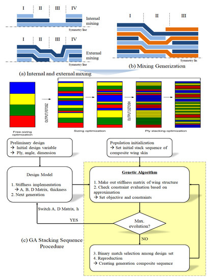
Figure 3.
Schematic overview of a GA stacking sequence optimization in combination with approximations.
The general genetic algorithm contains three operators: selection, crossover, and mutation. The selection operator selects chromosomes from the object group for reproduction, as shown in Figure 4c. The chromosomes selected are based on their suitability, and higher suitability results in a large group of fit individuals, and a lower fit gives them a long evolutionary time. The selection aims to reproduce objects close to the fitted values, so the fitted values should be selected following change and balance. The crossover operator produces two offspring by exchanging some of the before and after arrays of random locations in the selected chromosome. For the optimization of composite material structures, the genetic algorithm was implemented by FORTRAN, and the developed optimization code allowed the user to set design variables, limiting functions, and initial values and consisted of three main components. First, data files that set inputs, such as design variables, limiting functions, repeatability, initial values to perform optimization, and design opti-mization tools developed to solve various optimization problems, are available for linear and nonlinear optimization problems, regardless of the constraints or not. Second, factors within the range of design variables are randomly selected, and the upper factors that best match the objective function are selected and converged through generation. Because we randomly screen the stacking angles, we can find the overall minimum of the optimization problem. Lamination thickness optimization is performed to obtain a minimized mass satisfying global and regional limiting conditions. The convergence speed is also fast and performs similarly to the most preferred optimization algorithm. The genetic algorithm program code was implemented using FORTRAN, and an optimization analysis was performed. In genetic algorithms, mass is defined for minimization, and applying the same load case and stiffness optimization code applies the same constraints for deformation and buckling. Figure 3 and Figure 4 show the overall optimization process. First, primary stiffness conditions should be met using genetic algorithms. The optimized framework then maximizes the stiffness function by changing the stacking angle. The factors within the scope of the design variables were selected at random, and the top factors that best matched the objective function were selected and converged over the generation. The random selection of stacking angles allowed us to find the overall minimum of optimization problems. Finally, stacked thickness optimization was carried out to obtain a minimized mass that satisfies the limiting condition. Figure 4 shows the variable group exchange location criteria, and the ply is replaced based on the front of the chromosomes of the two stacks, the primary operator intersecting the two stacking chromosomes in the variable group, and the partial exchange of the stacking layers between the crossover points. Then, the crossover is exchanged exclusively within the variable group. Moreover, providing an opportunity to escape from optimal with mutant operators reverses a portion of the chromosome with tiny probabilities.
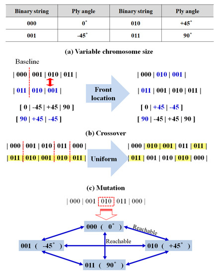
Figure 4.
Progress of genetic algorithm of binary code according to composite material stacking and angle (chromosome, cross-over, mutation).
2.3.2. Stacking Initialization and Replication
Genetic algorithms were sequentially performed to perform optimization, as shown in Figure 5. Initialization in composite material lamination begins by generating a minimum number of laminations. Then, any executable ply angle at which any position in the stack from the adjacent ply matches the design conditions can be selected. The angles were randomly selected and added to the stacking sequence. The same ply was added to the corresponding symmetric position in the next step, creating a different column in the stacking sequence. Crossover of the stacking sequence consists of choosing the same stack, and the stacking sequence selects the same number from two types and exchanges this subtype. A stack order mutation was randomly selected from a group of angles allowed at that location to form a ±θ change within the stack order, and crossover in the stack was randomly selected and exchanged between two identical stack groups in two shapes. The mutation was replaced by a randomly generated number between the minimum and maximum stack numbers. The selection of genotypes for replication begins with dividing populations into feasible and non-realizable designs. Genotype selection for reproduction after recombining was classified into a single population, including non-executable designs. Two of the genotypes were randomly selected and placed in a new group. There are three categories of deployed groups: viable genotypes, one possible genotype, and one not possible genotype. It was performed as necessary for total population generation, with many cross-operations generated by randomly selecting two contributing factors from newly placed groups. Eventually, a mutation according to the specified percentage was performed to complete the creation of a new entity.
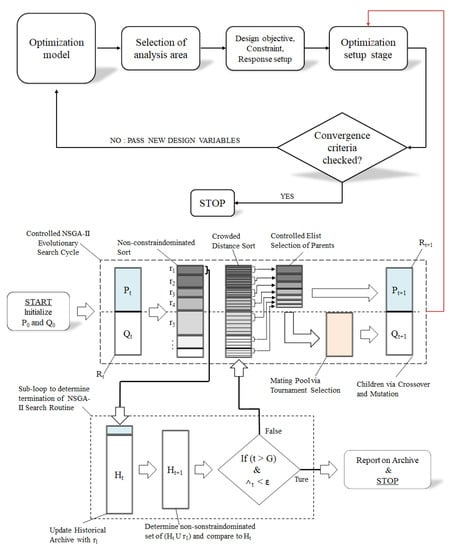
Figure 5.
Process of operating a genetic algorithm for a composite wing structure [32].
3. Design Setting of Optimum Design in UAV Main Wing Skin
For the battlefield to expand, reconnaissance UAVs also need to expand their mission radius and structural design to increase the flying time of drones. The time to stay in the mission area is much longer than crewed aircraft and can maximize the efficiency of the flight. Figure 6 shows the shape of UAV with a large wing structure applied in this paper. The application of a fixed, high aspect ratio of main-wing, considering the design weight and drag-reduction effects, and suitable features for surveillance and long-term construction should also be considered to reduce drag and improve production. The wing structure was applied with integral composites and cold bonding, preventing interference problems between the cladding and interior structures, and the optimum laminate design for each part was applied.
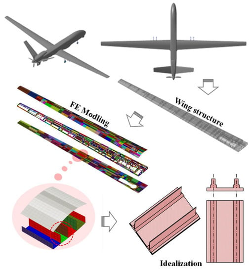
Figure 6.
Structure configuration and optimization area of UAV slender wing.
3.1. Idealization of UAV Wing Structure
The optimum design was carried out on reinforced composite laminates using genetic algorithms. The optimum design aims to find the reinforcement’s size and location to minimize weight, the skin and reinforcement stacks, and the number of stacks and stacks of the stiffener with a quasi-isotropic layer in a skin of a constant size. The stiffener performs the optimum design for the I-type case, and the stiffener and skin are laminated to be shaped and then glued or co-shaped. Figure 6 and Figure 7 show the overall shape, load, and boundary conditions. To determine the buckling load, the location and size of the reinforcement were arranged, as shown in Table 1, and the size of the stiffener was calculated for both the skin and reinforcement. Table 2 shows the properties and strength of the material applied to the blade type structure and skin shape, which are optimized objects. The material’s properties are the input value of the optimization analysis, and the strength value is used as a reference value for comparing the optimal design results.
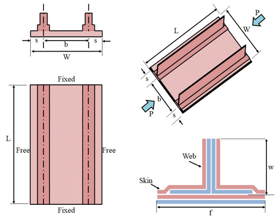
Figure 7.
The geometry of the blade stiffened the panel.

Table 1.
Geometry information and blade-type stiffener shape dimensions.

Table 2.
Composite material properties, wing skin material.
3.2. Factor and Design Variables for the Genetic Algorithm
The more constraints there are, the smaller the generation can find an optimization value. In this paper, only the constraints for the first failure mode and the buckling failure mode were used, and optimization was carried out based on the values used in the actual work. Positive margin of safety (M.S.) values used in actual work are generally determined by the experience of development projects or engineers, and it is recommended to set the minimum safety rate within the range of 0 < M.S. < 0.5. If the minimum safety rate is 0.5 or more, it becomes too conservative, which does not mean much of the structural optimization work. As shown in Equation (1), the Tsai-wu breakage theory used in the initial breakage mode showed the interaction of flat stress on the right side, and the failure index on the left side determines that breakage occurs if it is equal to or greater than 1. In this paper, the convergence value was set to 0.8.
where .
In the buckling failure mode, the safety rate was calculated using the interaction between the compression load and the shear load to verify the structural safety of the wing skin. In this paper, the convergence value was set to 0.05. In Equation (2), Nx,cr, Nxy,cr of the compression buckling critical load of the simple support structure is as follows:
Here, a and b are the shape dimensions, D11, D12, D22, and D66 are the reduced stiffness D matrix, and n and m are 1, 2, or 3.
The values of the factors used in this optimum design issue are shown in Table 3. The main design variables for performing the optimization analysis of the reinforced composite laminate are the number of laminations and the lamination angle. Only 0°, −45°, +45°, and 90° were used for the stacking angles, and the values of the genetic algorithm factors used in this optimization design problem are shown in Table 3. Because the proportion of appropriate evolution depends on the goodness-of-fit variance within the population, the size of the population was initially important, and 100 were selected as sufficient to produce the optimal string. Interbreeding typically involves an exchange between 0.5 ≤ p ≤ 0.8 probabilities, and within that range, the probability of interbreeding is 0.8, and mutations are the only source of evolution, using the probability of a mutation of 0.5 so that the population is not fixed at a particular location. Generation refers to the process of repetitive processes, such as selection, hybridization, and mutation, and generally, it is common to repeat generations of 50 to 500 or more, and here, it is 300 generations. This study was set based on general criteria because, when implementing genetic algorithms, various parameters cannot be optimized at once, and there are many things to discuss with various approaches and variables.

Table 3.
Parameters of the genetic algorithm and laminating guidelines.
The design guidelines for optimizing composite material stacking are as follows. The maximum number of laminated plies was set at least 6 to 40 sheets, and each ply thickness was 0.19 mm. A maximum of 10 drops between the lamination and lamination were proposed, and a maximum of 2 consecutive laminations were proposed. The fiber angle consisted of an interval of 45°, the outer ply was ±45°, and the maximum angle between adjacent stacks was 90°.
3.3. Convergence of Crossover Operator
Setting different conditions at intersections in hybridization operators impacts constraints’ convergence because they can produce more diverse objects. To confirm that convergence was improved over the initial hybridization operators according to the modified conditions of the cross operators, we compared the cross operators with the results of Picek et al. [33], comparing them under various conditions. Although the optimization program to which the genetic algorithm used in this paper was different, f(x) = −418.9829 was applied when the minimum value x = 420.968 was used in the range of [−500, 500] using the functional expression (4) of the same conditions used in Picek et al. [33].
By applying the same conditions, the results in Figure 8 show that the convergence of the hybridization operator in a form similar to those of Picek’s results was confirmed. After resetting the conditions, the convergence was better than that of the initial hybridization operator.
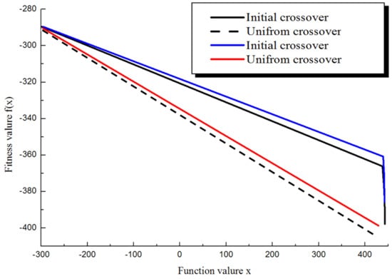
Figure 8.
Comparison of fitness values for crossover [33].
3.4. Idealization of UAV Wing Structure Objective
The goal of the optimum design applied was to find the design point minimizing the structural load by setting the buckling load as the design variable. First, the limitation condition on load was not applied to the design point in which the buckling load was lower than the design buckling point and increased the buckling load. Moreover, if the buckling load was higher than the designed buckling load, the load should be minimized to make no difference in weight but designed to increase the buckling load. The objective function was defined so that the overall directionality was dominated by the weight factor, but about 10% of the total directionality impacted the buckling load.
4. Optimum Design of UAV Wing Skin
Optimum Design Results by Genetic Algorithm
The initial stacking angle and the number of stacks applied to the idealized UAV wing cover were arbitrary, and the stacking angles were 0°, −45°, +45°, and 90°. The stacking angle was [04/−454/+454/904]s, and the thickness was measured to be 6.08 mm, and the weight was 0.30 kg. The design framework implements the stacking angle and number, designs variables defined on the composite wing’s outer shell, and performs calculations with genetic algorithms. The framework through the genetic algorithm was illustrated by calculating a combination of optimized lamination angles while converging constraints over 300 generations. The results in Figure 9 were obtained. The number of stacks applied to the initial wing outer skin was 32 sheets, consisting of [04/−454/+454/904]s at a rate of 25% of the laminating angle, and the ratio of the initial laminating number was 36%, −45° was 27%, and 90° was 18%, [06/−454/+453/903]s.
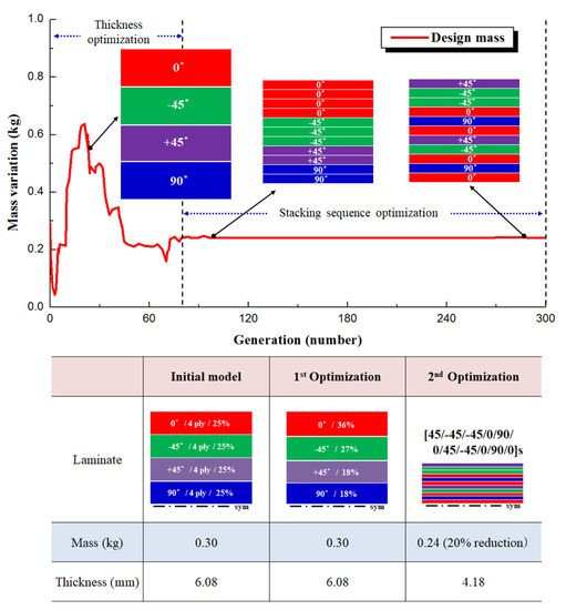
Figure 9.
Optimization results by lamination and weight variation.
Secondary optimization proceeded with optimization of the stacked number and the stacking angle as a result of primary optimization, the stacking angle was rearranged from 32 to 22 sheets, and the stacking angle was rearranged to [+45/−45/−45/−45/0/0/0/0/0]s, reducing the thickness and weight to 0.24 kg. From the initial shape to the secondary optimization, the number of stacked layers and the stacking angle were optimized, and the weight was reduced to about 20%.
Moreover, Figure 10 shows the mass optimization response according to generation and can be divided into two areas based on 30,000 evolutions. From 1 to 30,000 evolutions, the number of stacks changed significantly to find the optimal thickness, resulting in a width of significant changes in thickness and weight, while finding the optimal lamination angle ratio. When the design variable and the objective function begin to converge without changing from approximately generation 80, little weight change occurs, and the ratio of the optimal stacking water to the stacking angle is obtained. After that, the optimal stacking order was found by mixing the same stacking water and stacking angle up to 375 generations.
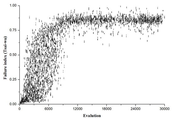
Figure 10.
Optimization result, failure index (Tsai-wu).
As the population progresses, Figure 10 shows the process of converging to the failure index, one of the design variables. Since it was in the process of finding the optimal thickness within the area of approximately 80 generations, the change in the number of stacks and the ratio of the stacking angle changed significantly, so the values were widely distributed in areas lower than the convergence value. As 80 generations passed, the number of stacked products with a certain thickness and stacking angle ratio was found, and the stacking order was optimized within the failure index convergence value area up to 30,000 entities. As a result, the outer shell of the unmanned aerial vehicle wing was optimized according to the design variables and objective functions to realize a weight reduction of about 20% and was designed in an optimal stacked structure. All restrictions were also satisfied. As shown in Figure 11, there were many substantial difficulties in comparing the convergence of genetic algorithms with other numerical algorithms. Because many variables exist due to the setting of various operators used in genetic algorithms, it cannot be determined which genetic algorithm is most promising. Therefore, it was compared to the convergence of design variables accordingly through optimization algorithms of the response surface methodology algorithm (RSM) and kriging algorithm other than the genetic algorithm. The response surface method is one of the statistical methods for modeling and analyzing the relationship between multiple variables and response variables, and is an approach to designing an experiment appropriately to determine the optimum of multiple variables. Kriging is an approach that calculates the average value of an already known function and predicts the value of the function at the point of interest.
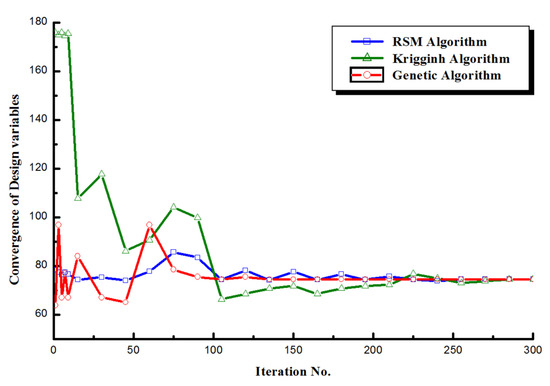
Figure 11.
Comparison results of algorithms.
Figure 11 compares the convergence of genetic algorithms, reaction surface methods, and kriging. Compared to other algorithms, the reaction surface method has a significantly smaller range of changes in convergence and converges approximately 250 times as the optimization process proceeds within a constant convergence. Kriging has the most extensive range of initial convergence changes, and after 100 times, optimization proceeded within an inevitable convergence and converged from 270 times. Genetic algorithms have a lower initial convergence than croaking, occur within a higher range than reaction surface methods, and converge at 80 iterations, which are relatively fewer cycles than other optimization algorithms. The reasons why genetic algorithms can have faster convergence conditions are as follows. Compared to the RSM algorithm and Kriging algorithm, there were no restrictions on design variables, limitations, repeatability, and initial input values. It is possible to randomly select factors within the range of design variables and to select higher factors that best match the objective function and converge through generations. The results of each optimization algorithm may be different depending on constraints, but as a result of approaching the current design variable condition, it was verified that the genetic algorithm converged relatively faster than the other optimization algorithms.
5. Verification of Optimum Design through Local and Global Analysis
In order to verify the optimal design results calculated by the genetic algorithm, structural analysis was performed by applying the stacked ply and stacking angle calculated by the framework using the genetic algorithm. Figure 12 shows the composition of finite element modeling; 650 shell elements and 1951 nodes were applied to the web; [+45/−452/+452/902]s were applied to the outer skin, and [+45/−45/−45/−45/0/90/0/+45/−45/0/90/0]s were calculated through genetic algorithms. The boundary condition was that both ends of the outer shell were held as fixed ends, and the side was set as free ends. Finally, the load was analyzed through NASTRAN by applying a compression load on both sides of the outer shell and applying one of the flight conditions.
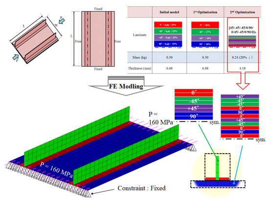
Figure 12.
Finite element modeling of the blade-stiffened panel.
5.1. Verification of Optimum Design through Static Analysis
In this section, the design verification of the reinforced composite laminates was performed through static strength analysis. For static strength, the damage index was determined based on the Tsai-wu failure index in Figure 13, which was a constraint condition. For an outer shell made of anisotropic material, it was necessary to determine whether to yield concerning the stress and the direction of the member.
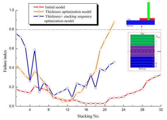
Figure 13.
Failure index results according to laminate sequence.
Figure 13 compares the Tsai-wu failure index values according to stacking order. In the case of the initial model, it existed at a position lower than the convergence value, and when only thickness optimization was performed while the optimization proceeds, the value exists at a position higher than the convergence value, so there was a broken ply. When the thickness and stacking order are optimized, it can be seen that a value close to the convergence value exists and satisfies the constraint of the 0.8 failure index. Figure 14 visually expresses the results of the failure index and shows the maximum failure index value for each model. Figure 15 compares whether the allowable stresses of compression and tension are satisfied. In the case of the initial model, the stress generated in the optimization model generated a stress value lower than the allowable stress, and as the optimization progressed, the stress value received by the envelope gradually increased. Therefore, it can be confirmed that a stress value occurred. Each stress distribution is confirmed in Figure 16 and Figure 17. Although there was a difference in the stress values, the overall stress distribution of the composite laminate had a similar shape.
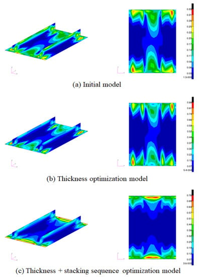
Figure 14.
Comparison of each model’s failure index results.
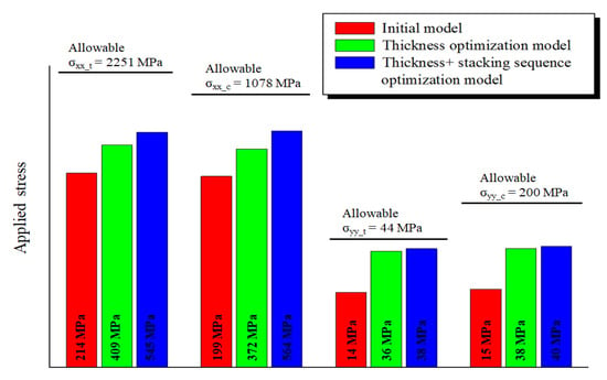
Figure 15.
Comparison of each model’s applied stress results.
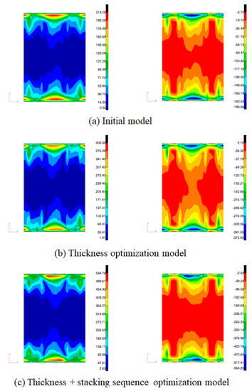
Figure 16.
Comparison of stress σxx results (left: tension, right: compression).
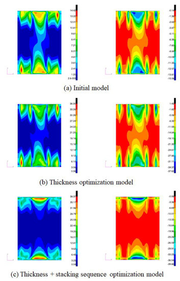
Figure 17.
Comparison of stress σxy results (left: tension, right: compression).
5.2. Verification of Optimum Design through Stability Analysis
To verify the structural stability of the wing, buckling analysis was performed using a finite element average internal load. Due to optimization, the outer skin was applied to the plate thinner, resulting in overall or local buckling more easily. Table 4 summarizes the eigenvalues and margins from the first to the fourth mode for each model as the results of the buckling analysis of the skin applying the optimal design. It can be seen that the initial buckling value of the initial model is 1.016 eigenvalue, and the minimum margin is 0.02. As the optimization proceeded, in the case of a model with only thickness optimization, the eigenvalue was 1.022, the minimum margin was 0.02, and it was confirmed that it did not converge to the minimum margin of 0.05, which is the constraint. This is because it can be seen that the minimum margin is 0.05, which converges to the minimum margin of 0.05, which is the buckling design requirement. Figure 18 visualizes and compares the primary mode results in the envelopes of each shape model. Figure 18 compares the buckling results of the outer shell in primary mode with the initial and optimization models. Figure 18a shows the shape of buckling by twisting outward from the area under compression load due to the thick outer skin, and Figure 18b shows the shape of buckling in the entire outer skin, not in some areas.

Table 4.
Comparison results of each model’s stability analysis.
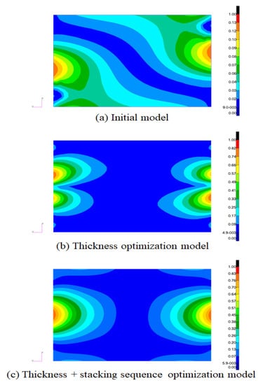
Figure 18.
Comparison of Buckling results, 1st Mode.
6. Conclusions
In this paper, the following conclusions were obtained using genetic algorithms to achieve weight optimization by carrying out the optimal stiffness design for numerous design areas of slender and long-wing structures. First, the design variables were calculated to quickly meet the prevailing design conditions, strength, and stability conditions of composite wing structures with variable stacking. As a result, the variable stiffness of the composite stacking optimization procedure was developed in the design of UAV wing structures. Furthermore, the stacking sequence of the proposed optimization process by applying genetic algorithms was able to obtain a reasonable distribution of stiffness while complying with the critical guidelines related to individual laminated ply designs.
The stiffness optimization process of the proposed composite wing structure was applied to the UAV wings. It was implemented as a partial model and validated through NASTRAN. The function of the stiffness optimization process was demonstrated by entering the response conditions set in many design areas of the wing structure, i.e., satisfying static strength and stability.
Author Contributions
Formal analysis, J.-H.J.; Investigation, J.-H.J.; Project administration, S.-H.A.; Software, J.-H.J.; Writing—original draft, J.-H.J.; Writing—review & editing, S.-H.A. All authors have read and agreed to the published version of the manuscript.
Funding
This research was funded by Shinhan University Research Fund, grant number [2021-0007].
Institutional Review Board Statement
Not applicable.
Informed Consent Statement
Not applicable.
Data Availability Statement
Not applicable.
Acknowledgments
This work was supported by the Shinhan University Research Fund, 2021.
Conflicts of Interest
The authors declare that there is no conflict of interest.
References
- Mamalis, A.; Manolakos, M.; Demosthenous, D.; Ioannidis, M.; Carruthers, J. Crashworthy capability of composite material structures. Compos. Struct. 1997, 37, 109–134. [Google Scholar] [CrossRef]
- Koohi, R.; Hossein, H. Nonlinear aeroelastic analysis of a composite wing by finite element method. Compos. Struct. 2014, 113, 118–126. [Google Scholar] [CrossRef]
- Vasiliev, V. Chapter 9—Thin-Walled Composite Beams. In Advanced Mechanics of Composite Materials and Structures, 4th ed.; Elsevier: Amsterdam, The Netherlands, 2018; pp. 591–685. [Google Scholar]
- Touraj, M.; Kayran, A. Geometrically nonlinear aeroelastic behavior of pretwisted composite wings modeled as thin walled beams. J. Fluids Struct. 2018, 83, 259–292. [Google Scholar] [CrossRef]
- Jiang, G.; Li, F. Aerothermoelastic analysis of composite laminated trapezoidal panels in supersonic airflow. Compos. Struct. 2018, 200, 313–327. [Google Scholar] [CrossRef]
- Gu, K.-N. Structural Analysis of Simplified Composite Wing Box. Korean Soc. Aeronaut. Space Sci. 1999, 27, 156–164. [Google Scholar]
- Lee, J.-J. Modified Design of Wing Structure for Long-endurance UAV. Korea Aerosp. Res. Institude Aerosp. Space Technol. 2002, 1, 179–185. [Google Scholar]
- Ln, L.; Kim, S.H.; Hong, C.S. Static Aeroelastic Analysis of Composite Wing. Korean Soc. Aeronaut. Space Sci. 1990, 18, 69–80. [Google Scholar]
- Han, C.-H.; Kim, E.-T.; Ahn, S.-M.; Kim, J.-W. Load Analysis of a Composite Canard Aircraft. Korea Aerosp. Res. Inst. 2002, 1, 8–27. [Google Scholar]
- Zhao, Q.; Ding, Y.; Jin, H. A Layout Optimization Method of Composite Wing Structures Based on Carrying Efficiency Criterion. Chin. J. Aeronaut. 2011, 24, 425–433. [Google Scholar] [CrossRef]
- Mastroddi, F.; Tozzi, M.; Capannolo, V. On the use of geometry design variables in the MDO analysis of wing structures with aeroelastic constraints on stability and response. Aerosp. Sci. Technol. 2011, 15, 196–206. [Google Scholar] [CrossRef]
- Haddadpour, H.; Zamani, Z. Curvilinear fiber optimization tools for aeroelastic design of composite wings. J. Fluids Struct. 2012, 33, 180–190. [Google Scholar] [CrossRef]
- Jing, Z.; Sun, Q.; Silberschmidt, V.V. A framework for design and optimization of tapered composite structures. Part I: From individual panel to global blending structure. Compos. Struct. 2016, 154, 106–128. [Google Scholar] [CrossRef]
- Chintapalli, S.; Elsayed, M.; Sedaghati, R.; Abdo, M. The development of a preliminary structural design optimization method of an aircraft wing-box skin-stringer panels. Aerosp. Sci. Technol. 2010, 14, 188–198. [Google Scholar] [CrossRef]
- Wan, Z.Q.; Hong, Y.; Liu, D.G.; Chao, Y. Aeroelastic Analysis and Optimization of High-aspect-ratio Composite Forward-swept Wings. Chin. J. Aeronaut. 2005, 18, 317–325. [Google Scholar] [CrossRef]
- Kameyama, M.; Fukunaga, H. Optimum design of composite plate wings for aeroelastic characteristics using lamination parameters. Comput. Struct. 2007, 85, 213–224. [Google Scholar] [CrossRef]
- Seresta, O.; Gürdal, Z.; Adams, D.; Watson, L. Optimal design of composite wing structures with blended laminates. Compos. Part B Eng. 2007, 38, 469–480. [Google Scholar] [CrossRef]
- Fan, H.-T.; Wang, H.; Chen, X.-H. An optimization method for composite structures with ply-drops. Compos. Struct. 2016, 136, 650–661. [Google Scholar] [CrossRef]
- Kim, T.-U.; Lee, S.-W.; Shin, J.-Y.; Han, I.-H. Layup Design of a Composite Wing under Gust Loading. Korea Aerosp. Res. Inst. 2006, 5, 7–11. [Google Scholar]
- Kim, J.-H.; Kim, C.-K.; Han, C.-S. Optimal Design of Composite Plate and Stiffened Panel Using Genetic Algorithm with Parallel Computing. Korean Soc. Aeronaut. Space Sci. 2002, 2002, 236–239. [Google Scholar]
- Yang, S.-H.; Ahn, J.-K.; Lee, D.-H. Multidisciplinary Optimal Design of a Transport Wing Configuration. Korean Soc. Aeronaut. Space Sci. 1999, 27, 128–138. [Google Scholar]
- Im, J.U.; Gwon, J.H. Transonic Wing Planform Design Using Multidisciplinary Optimization. J. Korean Soc. Aeronaut. Space Sci. 2002, 30, 20–27. [Google Scholar]
- Cho, S.-S.; Joo, W.-S.; Jang, D.-Y. A Study on the Optimal Design of Laminated Composites using Genetic Algorithm. Korean Soc. Precis. Eng. 1996, 1996, 729–737. [Google Scholar]
- Kim, S.W.; Kwon, J.H. Study of Aerodynamic Design Optimization Using Genetic Algorithm. Korean Soc. Comput. Fluids Eng. 2001, 6, 10–18. [Google Scholar]
- Mahfoud, S.; Derouich, A.; Ouanjli, N.E.; Mossa, M.A.; Motahhir, S.; Mahfoud, M.E.; Al-Sumaiti, A.S. Comparative Study between Cost Functions of Genetic Algorithm Used in Direct Torque Control of a Doubly Fed Induction Motor. Appl. Sci. 2022, 12, 8717. [Google Scholar] [CrossRef]
- Sitek, P.; Wikarek, J.; Jagodziński, M. A Proactive Approach to Extended Vehicle Routing Problem with Drones (Evrpd). Appl. Sci. 2022, 12, 8255. [Google Scholar] [CrossRef]
- Junqueira, C.; de Azevedo, A.T.; Ohishi, T. Solving the Integrated Multi-Port Stowage Planning and Container Relocation Problems with a Genetic Algorithm and Simulation. Appl. Sci. 2022, 12, 8191. [Google Scholar] [CrossRef]
- Chen, H.W.; Liang, C.K. Genetic Algorithm Versus Discrete Particle Swarm Optimization Algorithm for Energy-Efficient Moving Object Coverage Using Mobile Sensors. Appl. Sci. 2022, 12, 3340. [Google Scholar] [CrossRef]
- Cheng, J.B.; Li, X.; Mier, R.; Pun, A.; Joshi, S.; Nutt, S. Parametric Modeling, Higher Order Fea and Experimental Investigation of Hat-Stiffened Composite Panels. Compos. Struct. 2015, 128, 207–220. [Google Scholar] [CrossRef]
- Schlothauer, A.; Fasel, U.; Keidel, D.; Ermanni, P. High Load Carrying Structures Made from Folded Composite Materials. Compos. Struct. 2020, 250, 112612. [Google Scholar] [CrossRef]
- Sohst, M.; do Vale, J.L.; Afonso, F.; Suleman, A. Optimization and Comparison of Strut-Braced and High Aspect Ratio Wing Aircraft Configurations Including Flutter Analysis with Geometric Non-Linearities. Aerosp. Sci. Technol. 2022, 124, 107531. [Google Scholar] [CrossRef]
- Jiang, R.; Ci, S.; Liu, D.; Cheng, X.; Pan, Z. A Hybrid Multi-Objective Optimization Method Based on NSGA-II Algorithm and Entropy Weighted TOPSIS for Lightweight Design of Dump Truck Carriage. Machines 2021, 9, 156. [Google Scholar] [CrossRef]
- Picek, S.; Golub, M. Comparison of a Crossover Operator in Binary-coded Genetic Algorithms. Wseas Trans. Comput. 2010, 9, 1064–1073. [Google Scholar]
Publisher’s Note: MDPI stays neutral with regard to jurisdictional claims in published maps and institutional affiliations. |
© 2022 by the authors. Licensee MDPI, Basel, Switzerland. This article is an open access article distributed under the terms and conditions of the Creative Commons Attribution (CC BY) license (https://creativecommons.org/licenses/by/4.0/).