Article

Optimal Kinematic Task Position Determination—Application and Experimental Verification for the UR-5 Manipulator

by
Charalampos Valsamos
1,*,
Kanstantsin Miatliuk
2,*,
Adam Wolniakowski
3,
Vassilis Moulianitis
1 and
Nikos Aspragathos
4
1
Department of Product and Systems Design Engineering, University of the Aegean, Konstantinoupoleos 1, 84100 Ermoupolis, Greece
2
Department of Robotics and Mechatronics, Bialystok University of Technology, 15-351 Bialystok, Poland
3
Department of Automation and Robotics, Bialystok University of Technology, 15-351 Bialystok, Poland
4
Department of Mechanical Engineering and Aeronautics, University of Patras, 26500 Patras, Greece
*
Authors to whom correspondence should be addressed.
Appl. Sci. 2022, 12(18), 9352; https://doi.org/10.3390/app12189352
Submission received: 5 July 2022 / Revised: 26 August 2022 / Accepted: 1 September 2022 / Published: 18 September 2022

Abstract

:
A method for determining the optimal position of a robotic task within a manipulator’s workspace considering the minimum singularity free paths in joint space in order to achieve a high kinematic performance is presented. The selected performance criterion was the minimization of the joint velocities during task execution under a given end effector velocity. The proposed method is applied to place kinematic tasks for a UR-5 manipulator. Joint speed measurements are compared for the optimal and the “bad” task positions and the results show that at the optimal position, lower joint speeds are exerted during task execution.

1. Introduction

In robotic applications, it is crucial to reduce the overall operational cost and increase productivity, which usually results in the need to reduce the necessary cycle time of robotic tasks. Particular attention must be paid to the optimization of the robot end effector motion considering various criteria such as minimum execution time and/or energy consumption, smoothness, as well as robot constraints such as maximum joint velocity and acceleration, accuracy, workspace constraints such as obstacles and/or process constraints such as time window or end effector velocity and acceleration limits.
Among the most common methods to optimize robotic operations is the placement of the task to be executed at an optimal location with respect to the robot’s base or vice versa. In most cases, the proposed methods comprise three key aspects: (a) the introduction of a performance measure, (b) an optimization method and (c) an optimal search method.
Performance measures are at the core of such optimization methods. Their use allows for the quantification of different aspects of the manipulator’s operation targeted to be optimized. A wide range of different kinematic indices, either local, task based or global have been proposed in the relevant literature. Local indices are configuration dependent, i.e., dependent on the current posture of the manipulator at a given point. Task-based indices are usually formed by the algebraic manipulation of local indices along the given kinematic task, as such being dependent on the manipulator’s configurations during task execution. Global indices are configuration independent, since they represent the overall measure of a performance aspect across the whole manipulator’s workspace.
Among the well-established indices in the relevant literature is Yoshikawa’s manipulability index [1], providing a measure of the manipulator’s ability to move in any given direction from a given configuration. However, it presents a number of inherit limitations, such as scale, order and dimensional dependency as well as the fact that in its general form is an unbounded index. Moreover, it does not take into account the direction of motion, since it examines all possible directions of motion from a given configuration. However, various improvements have been proposed to overcome its limitations [2]. Other well-established indices include the Minimum Singular Value [3] and the Jacobian condition number [4]. The first examines the “most difficult” direction of motion of the end effector, providing a concise means to determine the manipulator’s posture distance from a singularity as well as a measure of the upper bound of the velocity the manipulator may move in all directions. The latter examines both the “most difficult” and the “easiest” motion directions from a given posture, providing a concise measure of accuracy of the transmission of joint speeds to end effector velocity. Similar indices of the latter are the Local Condition Number and the Reciprocal Local Condition Number [2]. However, these indices retain the limitations of the manipulability index, due to being dependent on the manipulator’s Jacobian. In the case of the determination of the effectiveness of the transmission of joint speeds to the end effector velocity, Dubey and Luh proposed the Manipulator Velocity Ratio (MVR) [5]. The measure examines the transmission in a given direction of motion of the end effector, providing a more concise view of the manipulator’s ability to move in a specific direction. Moreover, it also provides a measure of the required values of the latter in order to achieve a specified end effector velocity. A thorough and comprehensive review of performance indices may be found in [2].
Optimal kinematic task placement methods utilize some of the above-mentioned indices depending on the manipulator’s performance aspect considered for optimization to formulate the optimization problem’s mathematical expression, i.e., the problem’s objective function. The formulated problem is then solved utilizing an optimal search method. Some of the most recent and characteristic examples from the relevant literature are the following.
As already stated, the chosen index is the cornerstone of any proposed optimal task placement problem. In the case of kinematic tasks, such as those addressed in this work, a kinematic index is used.
A local kinematic index provides quantifiable information of a selected aspect of the manipulator at a given point within the manipulator’s workspace. For example, Nguyen et al. in [6] used Yoshikawa’s manipulability index as the index for their proposed method of optimal task placement within the workspace of a surgical robot.
One example of a task based kinematic index was the Approximation of the Minimum Manipulator Velocity Ratio (AMMVR) presented in [7]. The index is formed by calculating the value of the Manipulator Velocity Ratio (MVR) [5] at several end effector frames along a 3D curve representing a trajectory to be followed by the robot’s tool frame and selecting their minimum value as the task-based index value. The “approximation” description was used because the local index value (MVR) was calculated at a given number of frames along the trajectory.
In a similar fashion, Baizid et al. [8] proposed a task-based index consisting of the minimum time required by the end effector of a manipulator to move between two task points within its workspace. The index was formed locally as the maximum value of the time required to traverse from one point to another. The index was then transformed to a task-based index by selecting the minimum value of all the local index valued determined for the given task. Liu and Cavunsoglu in [9] used a task-based index based on the manipulability index to determine the optimal placement of a patient for the optimal execution of a robotic minimal evasive surgery task. The task-based index resulted from the integration of the local index value versus time along the required task trajectory divided by the total task execution time.
The problem of determining the optimal task placement may be reversed to the problem of determining the optimal robot base placement when the task(s) location(s) is(are) given. In such cases, usually a global kinematic index is proposed, in order to determine the overall best position for the robot’s placement, such as the reachability measure proposed in [10]. The index was a measure of the reachability of different tasks in a given workspace that the manipulator must be able to reach. Dharmawan et al. on the other hand utilized a task-based index for the determination of the optimal location of a manipulator’s base for a given kinematic task [11]. Their index was the sum of the mean manipulability index throughout the possible robot base locations.
In some cases, multi-criteria indices may be presented for providing a measurable function for the determination of the optimal location of the robot’s base. Doan and Lin in [12] presented such an index formed by four criteria, all of which were expressed as a function of the robot’s kinematic and structural properties and constraints. The first one depicted the joint’s limitations, the second one was the possibility of the robot reaching a singular configuration, the third one depicted the possibility for the requirement of collision avoidance and the fourth was defined as the ratio of the distance between the robot’s base frame origin to the commanded target frame of the end effector by the theoretically reachable range from the origin of the robot’s base frame. Four weighting factors were introduced for each of the criteria and the index was defined either as the sole value of the fourth criterion or the maximum value of the other three criteria.
In the context of the proposed methods, it can be said that the approaches used are similar. An objective function is formed using the introduced or selected local, task based or global kinematic index and the objective function is then subject to minimization [8] or maximization [6,7,9,10,11,12]. In all cases, the manipulator kinematics were at the core of the determination of the optimization process.
Due to the complexity of the problem, the search method is usually based on soft AI techniques such as Genetic Algorithms [6,7,8,10]. However, most of these proposed methods are applied offline and the results presented by the authors are based on simulations rather than experimental verification. From the presented works, only [12] is verified using a physical system. As such, these results represent the upper limit of the ones expected from the physical system. One such simplification is that when kinematic tasks are simulated, the dynamics of a manipulator are either not considered or simplified to a degree that their influence is negligible.
The present work presents a method for the optimal placement of a kinematic robotic task inside the workspace of a manipulator. The presented approach presents similarities to previous work by the authors such as [7]; however, its novelty is based on two respective points. Firstly, the optimal location of a kinematic task within the workspace takes into consideration the minimum singularity free paths that the manipulator’s end effector may utilize in its motion between different task points in the respective sequence that describes the task. This was not considered previously, and singularity avoidance was assumed on the basis of the index value at the considered task points. As such, there was no guarantee that the manipulator would not reach a singular posture during its motion between consecutive points. The consideration of the minimum singularity free paths allows for the derivation of a solution ensuring the execution of the task under the certainty that during the end effector motion the manipulator will not reach any singular configuration. This consideration was first presented in [12]; however, in a global fashion. In this paper, the avoidance of singular postures during the end effector motion is conducted in a task-based fashion.
Moreover, the simulation results for the optimal task placement are experimentally verified in order to provide an insight on the validity of the computational results of the proposed method, i.e., the execution of a kinematic task under constant increases kinematic performance.
The main aim of the method presented is to allow the designer to derive the optimal location of a kinematic task within the robot’s workspace, so as the required joint speeds for the generation of the required end effector velocity will be minimized. As a process is proposed to develop task-based kinematic indices base on well-established local indices, such as the Manipulator Velocity Ratio [5,7]. In order to achieve the prescribed aims, the methodology presented aims for the maximization of the minimum value of the developed task-based kinematic performance indices. Given the computational results from the application of the proposed method, a physical experimental workcell is setup and the examined tasks are executed. Two types of robotic tasks are considered—a pick and place and a path-following task. The experimental workcell setup utilizes a UR-5 serial manipulator [13]. Additionally, in order to determine the validity of the method both the optimal results as well as the results for a considered “bad” task placement location are utilized for the experiments, and in both cases end effector velocity and joint speeds along with the required time for task execution are measured. The experimental results for both the “bad” and “best” task placements are evaluated in contrast to examine the validity of the proposed method.

2. The Proposed Approach

Generally, in kinematic robotic tasks, the end effector of a robot is required to reach a number of task points or to follow a given path with its end effector, presenting a prescribed orientation of the end effector local frame. These points may present task points where an action is executed or present intermediate task points along a curve/path to be followed by the robot’s tool in a specific sequence, while the end effector exhibits smooth motion along the path under prescribed acceleration and velocity requirements.
As such, a means to achieve an increased kinematic performance during task execution, commonly utilized, is the placement of the kinematic task to an optimal location within the robot’s workspace [7]. In the case of the method presented, kinematic tasks are described as collections of task points that the end effector must visit and move along under given orientations.
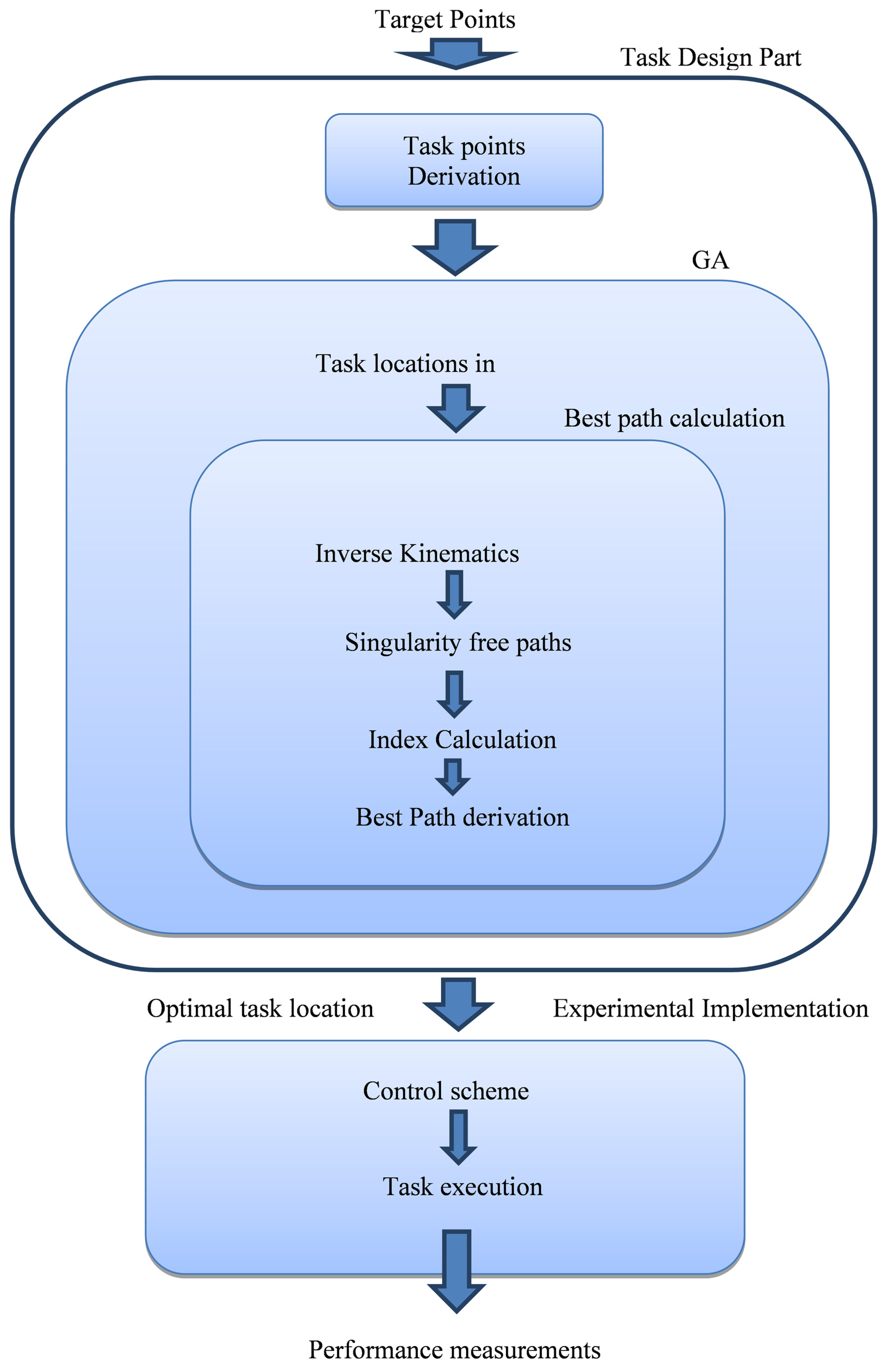
The presented methodology may be segmented to two parts that are interconnected: a part that enables the work cell’s layout design and a part where the experimental process takes place. The whole process is presented in Figure 1.
(1)
Layout Design
During this initial stage, the derivation of the kinematic tasks optimal location is computationally derived, having as an input the collection of the task points that compose the task. As such, a Local Coordinate System (LCS) is considered to be placed to the initial task point to be visited, which depicts the orientation and location of the end effector at it. All other task points are therefore referenced to the LCS. Therefore, the inputs for this stage are the position and orientation of the local coordinate systems, relative to the LCS, and the sequence with which they are to visited by the end effector during the execution of the task.
In order to the better interpolate the motion between the task points, intermediate points are initially determined between each consecutive task points pair. The designer is allowed to set the number of intermediate points to be placed as per task requirements.
Another process in the computational part involves the determination of the best possible paths between consecutive task frames. Therefore, a task-based kinematic performance index is developed so as to allow the quantification of the required kinematic performance aspect to be optimized during the execution of the task. The process is repeated for each pair of consecutive task frame and is listed as follows:
  • Initially, the possible configurations (postures) of the manipulator at each task and intermediate frame are determined by the solution of the inverse kinematics problem.
  • The possible singularity free paths with respect to the end effector’s motion between task frames are determined in the manipulator’s configuration space.
  • The task based index value is evaluated for the derived singular free paths.
  • Based on the index value along the path the best path is determined.
Finally, a Genetic Algorithm is employed to conduct the search for the optimal location of the kinematic task. At the end of the search process the optimal location of the kinematic task is determined.
(2)
Experimental Implementation
The experimental implementation inputs are the determined optimal position and orientation of the LCS with respect to the BCS (Base Coordinate System of the Robot), the referencing of the task frames to the LCS and the sequence with which the end effector approaches the task frames. These are used to setup the task execution to the robotic workcell that will undertake the task execution.

2.1. Formulation of the Optimal Task Placement Problem

Formally, the kinematic task can be considered as one where the end effector of the robot is to reach k task frames under a required orientation requirement at each one with given orientation. The task frames respective location to each other are also given. A graphical representation of this consideration is illustrated in Figure 2. In Figure 2, the manipulator is placed at an arbitrary posture, and the kinematic task is represented by the collection of the respective task points presented. At each task frame the required orientation of the end effector’s frame is also depicted. As such, the task frame may be considered as as {Pi}, i = 2, …., k. In Figure 2, the main coordinate systems required are that of the manipulator’s base (BCS) denoted as {B}, that of the end effector tool (TCS) denoted as {T} and that of the initial task frame of the kinematic task (to which all other task frames are referred to) (LCS) denoted as {L}. Therefore, for each task frame, it stands that:
Applsci 12 09352 i001
where LRi is the 3 × 3 matrix representing the orientation of the ith frame coordinate system relative to {L} and Lpi is the 3 × 1 vector providing the location of the ith frame with respect to {L}. As such, it is possible to determine the overall task location with respect to the robot base {B}, as:
Applsci 12 09352 i002
Considering this definition, the optimal task placement problem is transformed to the problem of the optimal placement of {L} relative to {B}.
The task frames can be utilized to determine k segments linear of motion that depicts the path to be followed by the end effector. Here, the selected kinematic performance aspect to be optimized is defined to be the transmission of the joint speeds to end effector velocity. Given that, the selected local kinematic performance index utilized for the task-based performance index is the Manipulator Velocity Ratio (MVR) [5].
In order to determine the value of the index, the direction of motion of the end effector must be known. However, since a linear motion is considered to take place between frames in the cartesian space, it is quite simple to derive it for each path segment and, as such, for each segment, the index can be determined as:
r vi , j B p L , θ _ = 1 / u vi T J vi , j B p L , θ _ J vi , j B p L , θ _ T 1 u vi ,    i = 1 , , k , j = 1 , , 8 ,
where j is the index for the corresponding inverse kinematic solution for the ith frame. Vector uvi is the unit vector depicting the direction of motion for the given segment, J(vi,j) is the manipulator’s Jacobian evaluated at the ith frame with the jth configuration and r(vi,j) is the MVR evaluated at the ith frame and jth configuration. However, the different solutions of the inverse kinematics to the ith and (i + 1)th frames provide a significant number of different motion paths between them in the manipulator’s joint space. Therefore, the selection of the best path is required and this selection is based on the determination of the shortest singular free path.
Figure 2. UR-5 manipulator and the base {B}, end effector {T}, local {L} coordinate systems, and task frames {Pi}.
Applsci 12 09352 g002

2.1.1. Shortest Singular Free Paths in the Configuration Space

As presented in [14], no-generic geometries divide the space of 3R geometries into disjoint sets which have homogeneous topological properties. As such, given the maximum four solutions at a given point frame in the workspace of a 3R geometry, provided by the solution of the inverse kinematics problem, four disjoint sets can be produced. Therefore, in the case of non-cuspidal manipulators, the singularity locus separates the inverse kinematic solutions, forcing the manipulator to transverse singular points during the altering of its posture along the motion between task frames. The disjoint sets and their correspondence determination depend on the manipulator’s Jacobian matrix determinant |J|. In previous work, it was shown that this value is independent to the value of the first joint variable [15].
Here, the UR-5 robot is a 6 D.o.F manipulator and, as such, presents a maximum of eight postures at a given frame as resulting by the solution of the inverse kinematics problem. It is possible to derive the determinant of the Jacobian matrix of the UR-5:
J = L 2 L 3 sin q 5 2 d 5 cos q 2 + 2 q 3 + q 4 L 2 sin q 2 + q 3 d 5 cos q 2 + q 4 + L 3 sin q 2 + L 2 sin q 2 q 3 L 3 sin q 2 + 2 q 3
In order to determine the singularity locus for the UR-5 robot, the equation considered is |J| = 0. This results in the following solutions:
E 1 = 0 , where E 1 = sin q 5
q 3 = k π ,   k = 0 , 1 , 2 , ,
E 2 = 0 ,   where   E 2 = d 5 cos q 2 + 2 q 3 + q 4 L 2 sin q 2 + q 3 d 5 cos q 2 + q 4 + L 3 sin q 2 + L 2 sin q 2 q 3 L 3 sin q 2 + 2 q 3
For the UR-5 robot’s eight aspects defined by [q2 q3 q4 q5] in the configuration space, there are eight solutions of the inverse kinematics problem included in each. The Jacobian matrix determinant sign, however, is preserved for each aspect. Given the above combinations, a total number of 64 available paths in the configuration space are present for the motion of the end effector between two given frames. These combinations stem from the possible configurations of each of the 6 joints of the manipulator as determined by the solution of its inverse kinematics. By the shortest path, the direct motion between two frames in the configuration space is considered. However, only eight of these paths allow the motion of the robot from the first to the second frame to proceed while not meeting a singularity point in the configuration space.
The determination of the singular free paths process is conducted utilizing the data in Table 1. There, the sign of the Jacobian matrix determinant is evaluated at each frame and allocated to the corresponded aspect. Therefore, singular free paths are those that the sign of the determinant is preserved for both frames or in the case the frames configurations are existent in the same aspect.

2.1.2. Optimal Task Position Determination

The optimization process aims at improving the overall transmission of the joint speeds utilized, to achieve given end effector velocities.
The objective function is therefore defined as the maximum minimum overall value of the MVR in the k points of the 8 paths:
R v B p L , θ _ = max j min i r vi , j B p L , θ _ 0 ,           if      J vi , j = 0 , i = 1 , , k ,       j = 1 , , 8 ,
where Rv is the objective function.
Therefore, it is possible to derive the solution to the considered problem as:
B p L , θ _ = arg max R v B p L , θ _ ,
As such, the method’s outputs are the orientation and position of {L} with respect to {B}. Since the required end effector postures for each of the task frames with respect to {L} are a priori given, deriving them requires a simple calculation of the respective transformation.

2.2. Derivation of the Optimal Solution to the Considered Problem

In the previous parts of the layout process described, the intermediate path segments along the motion between task frames were determined, and the task-based kinematic performance index was structured. Given these, the objective function of the considered problem was defined. In order to conduct the search for the optimal solution, a Genetic Algorithm is deployed.
In order to utilize the GA, the variables of the optimization problem must be appropriately represented. Here, a chromosome consisting of six digits of real numbers is utilized. These six digits correspond to the position of {L} with respect to {B} as [x,y,z] coordinates and the Z-Y-Z Euler angles of {L} with respect to {B}. As such, the six digit chromosome is presented as:
x y z p o s i t i o n θ z θ y φ z o r i e n t a t i o n ,
The value ranges for the chromosome’s genes were: x, y, z ∈ [0.1, 0.5] (in meters) and φz = θy = 0, θz∈ [−π/2, π/2].
With respect to the GA operators utilized:
  • Reproduction was conducted in an elitist manner, ensuring the survival of the best individuals in the next generations (60% of the population).
  • Crossover was conducted using a one-point crossover method. The parents pairs were arbitrarily selected and the cut point was also arbitrarily defined. Here, the population selected corresponded to the 20% of the total population.
  • Mutation was conducted in a single point manner. A random digit was selected and reset to an arbitrary value. Again 20% of the population was selected to undergo mutation.
Given the objective function defined in Equation (8), the fitness function of the GA can be defined as:
fitness = 1 R v B p L , θ _ ,
Additionally, it is subject to minimization. Two conditions of search process termination were included, i.e., a maximum allowed generations number and a maximum number of iterations where there was no change in the fitness function value. The first was set to 100 generations and the second to 10 generations. A population of 40 individuals was utilized in each generation.
The outputs of the design part are the optimal location and orientation of all the task frames relative to {B}. These are the inputs to the experimental implementation (Figure 1). The outputs of the experimental implementation are the manipulator’s joint velocities during task execution.

3. Application of the Proposed Method

The proposed methodology was applied to two different tasks, i.e., a pick and place task, and a trajectory following task. The experimental setup utilized an UR-5 6 D.o.F. robot. In order to validate results, for each type of task, two different task locations were derived: the optimal one and a “bad” location for reasons of comparison. The considered “bad” location was derived by hard-stopping the Genetic Algorithm after a first feasible solution to the optimization problem was determined. This ensured that placing the asks in the “bad” location derived would allow for their execution since workspace constraints of the manipulator were not reached (i.e., task points located outside of the manipulator’s workspace or at singular configurations).

3.1. Case Study Robotic Tasks

Two robotic tasks are considered for the application of the presented method. A pick and place task and a path-following task.

3.1.1. Pick and Place Task

The pick and place task is defined as one where the robot will have to pick up different types of pegs placed on a base in its workspace and place them on a similar base at some distance. The pegs are different in shape, one being cylindrical and the other one being cuboid (Figure 3a,b). Each base has two holes of according shape and dimensions for the insertion of each peg, (Figure 3).
The {L} for the considered task is placed at the geometrical center of the top face of the pick up base (Figure 3). On each of the two pegs, a grasping frame was placed describing the end effector position and orientation in grasping the object.
The placement base was placed at the distance of 50 mm from the center of the {L} (pick up position) and the “place position” distance of 100 mm from “pick up position”, i.e., 50 mm from the center of {L}.
As such, regarding the cylindrical object, the following points were used for the task (presented in distances relative to the {L}).
  • Lp1: Hover point over cylindrical object pick up [−0.05,0,0.25]T,
  • Lp2: Grasping point of cylindrical object [−0.05,0,0.1]T,
  • Lp3: Hover point over cylindrical object placement [0.05,0,0.25]T, and
  • Lp4: placement point of cylindrical object [0.05,0,0.1]T.
Therefore, the task sequence was: Lp1, Lp2, Lp1, Lp3, Lp4, and Lp3. For the orthogonal part, the task point sequence was similar.

3.1.2. The Path-Following Task

A 2D Lissajous curve was considered as the path that the manipulator’s end effector had to follow in an analogous way with a prescribed end effector velocity. The trajectory was considered to lie on a xy plane at some given z-axis level. The curve equations are the following:
x t = x o + cos a A x cos ω x t sin a A y sin ω y t ,
y t = y o + sin a A x cos ω x t + cos a A y sin ω y t ,
z t = z o ,
where x0, y0, and z0 depict the coordinates of the center of the curve, Ax and Ay are the major and minor axis length, ωx and ωy are the angular frequencies (in radians), and α is the angle of the orientation of the curve.
To follow the trajectory for the manipulator tool frame, an interpolation process was conducted by placing intermediate task frames along the end effectors path, determined by the use of straight line segments from the starting point of each intermediate path segment. All intermediate points generated were referenced to {L}.

3.2. Determination of the Optimal Task Location Results

Using the proposed methodology, the location of the tasks were derived. For comparison, a respective “bad” task location was also derived for both tasks, by simply interrupting the optimal search at the first non-singular task placement.
For reference, the robot’s joint angles for the pick and place task (cylindrical object) (in rad) for the optimal placement are presented in Table 2 and for the «bad» placement in Table 3.
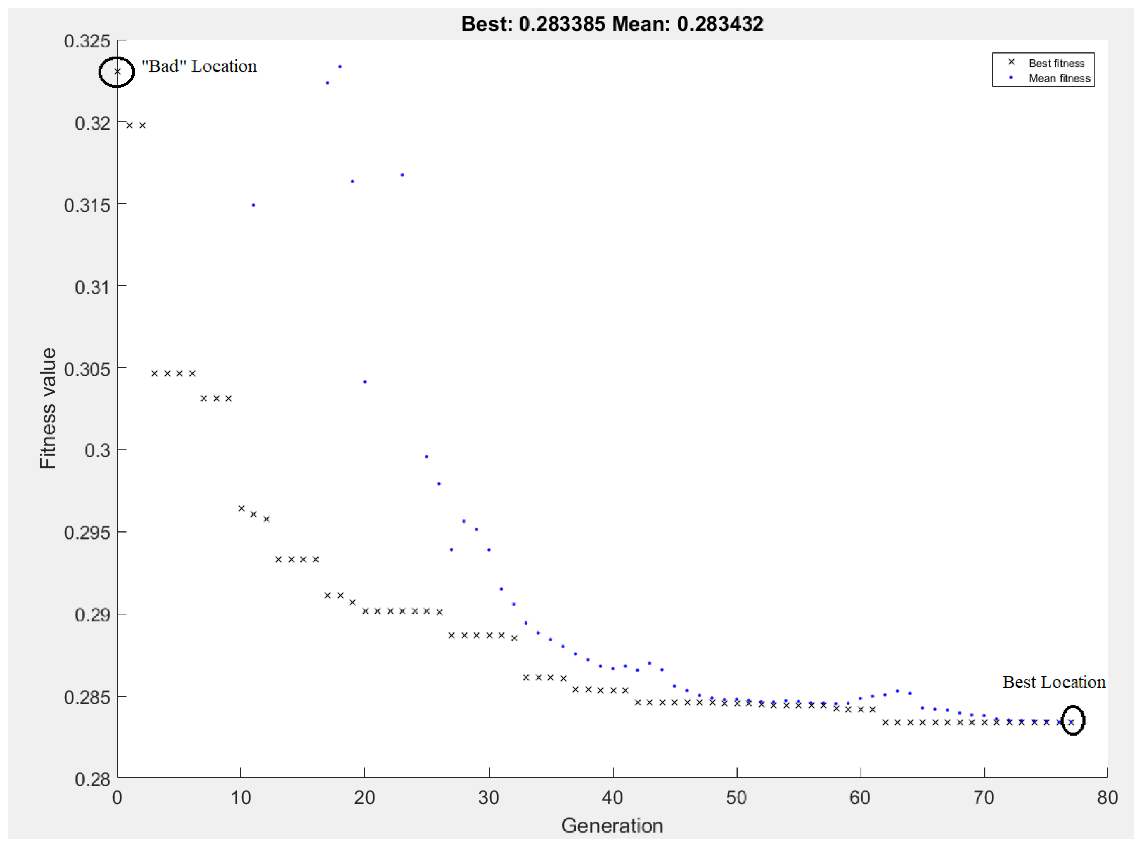
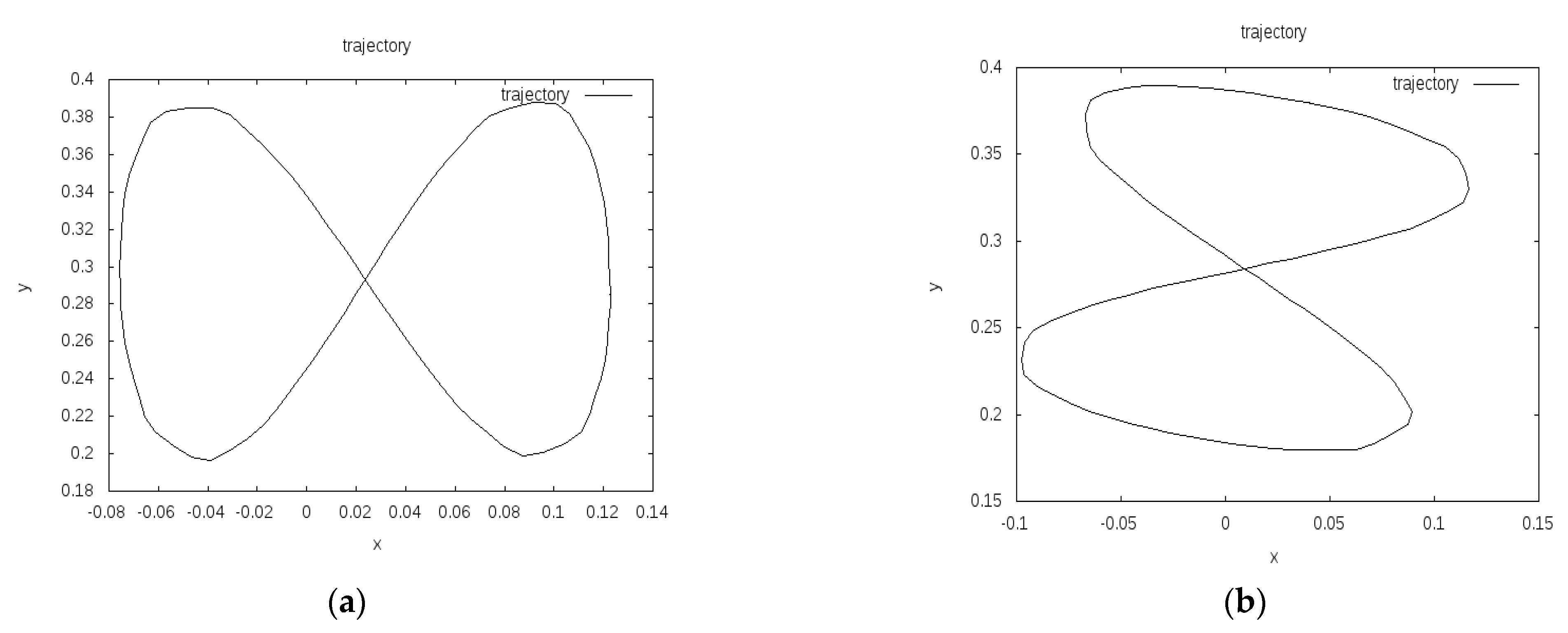
Accordingly, the best and bad locations for the path-following task are presented in Figure 4a,b, respectively. Given the fact a given end effector velocity would be utilized to execute the task, the total task execution time for both placements of the task was the same. Figure 5 presents the step by step process of the optimization process during the operation of the GA and the corresponding steps where the “bad” and best task locations were derived. As shown in Figure 5, the bad task location was determined utilizing the feasible solution of the GA derived at its first iteration, while the best task location was determined utilizing the optimal derived solution.
Moreover, a sensitivity analysis with respect to the task placement coordinates was conducted about the derived optimal task placement. The results are depicted in Figure 6, where Figure 6a presents the variance in the fitness function value with respect to a ±5% variation in the x-position of the task around the best location, (Figure 6b) the according fitness function value variation to a respective variation of the y position, (Figure 6c) the according fitness function value variation to a respective variation of the z position and (Figure 6d) the according fitness function value variation to a respective variation of the task orientation. As seen, the variation of the position aspects of the task induces a negligible variation to the fitness function value derived (less than 1%).
The effect that the number of intermediate points placed between consecutive task points has on the optimization process was also examined, with respect to the path-following task. Table 4 presents the optimization process duration and derived result with respect to the number of intermediate points inserted in each path segment. The task points set along the path and the population number were the same for all simulations. As seen, the increase in the number of points increases the required computational time, however the fitness function value is improved.

4. Experimental Setup

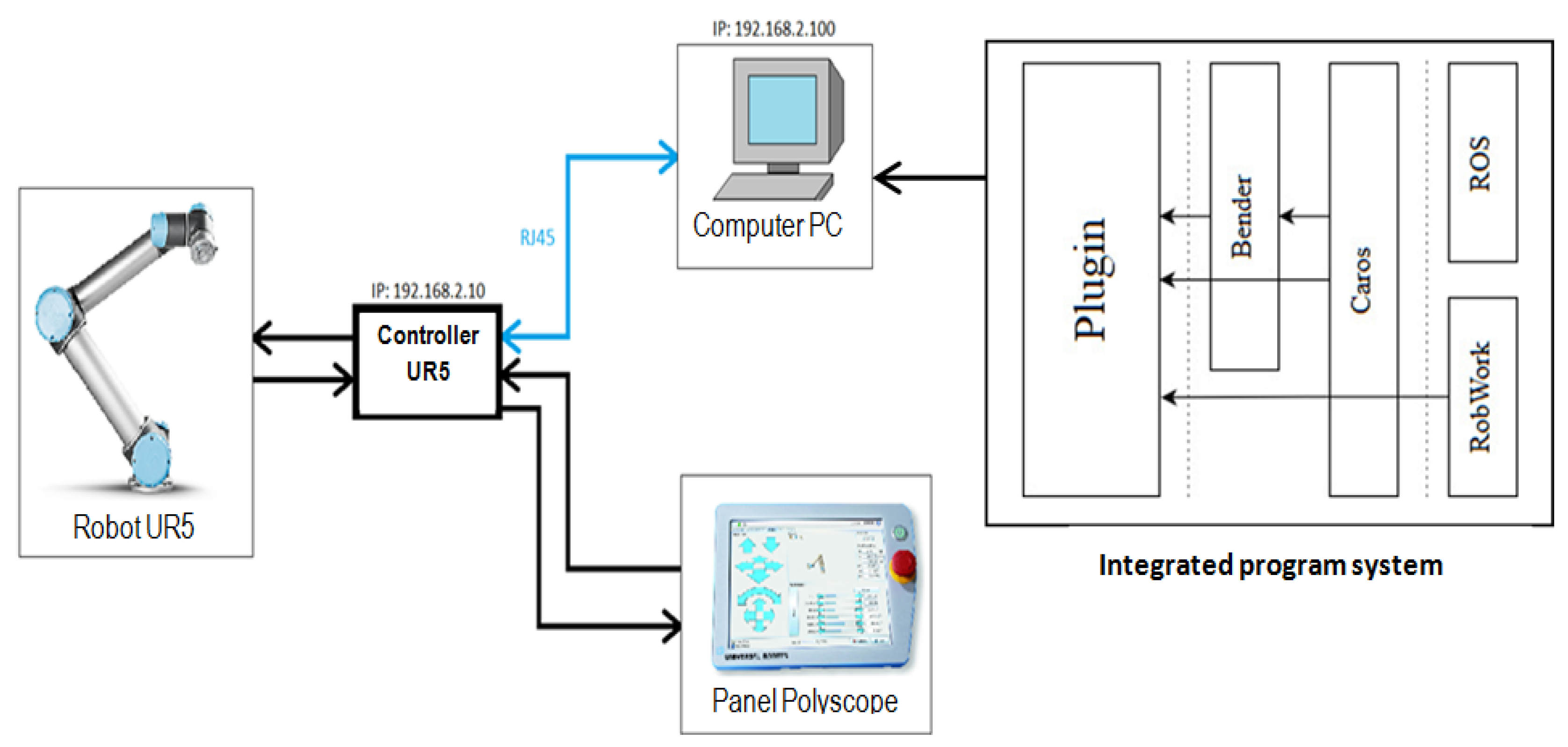
The task optimal location experiment was performed at the robotic stand of the Robotic Systems Lab., Bialystok University of Technology (BUT), Białystok, Poland. The setup consists of two UR robot arms equipped with Schunk EVG55 grippers which are mounted on an aluminum frame. The hardware control stack consists of RobWorkHardware drivers and CAROS ROS nodes. The user interface and visualization is implemented as a RobWorkStudio plugin (see Figure 7). The scheme of all the subsystems interactions of laboratory setup in a ‘pick-and-place’ process performed by UR-5 is presented in Figure 8. Here, the Plugin module belongs to application level of the integrated program system, Bender and Caros units belong to the hardware control level, and the RobWork and ROS units form the system level [16].
For the realization of the pick and place task, the built-in URScript [17] functions movep, movel and movej were used. The functions allow for linear robot movement in both the configuration and the Cartesian space as well as the control of the speed and velocity of the movements. For both pick and place tasks, the end effector velocity during task execution was set to be the same.
For the trajectory following task, the movement of the robot was controlled by accessing the servoj function with the target configuration updated with the rate of 125 Hz. The end effector velocity during task execution was constant. The URScript functions were accessed through the wrappers implemented in the Caros and the Bender packages. The control points of the trajectory were defined and visualized through the plugin interface (see Figure 7) based on the RobWork package [18]. The subsystems were coordinated through the use of ROS (see Figure 8).

4.1. Pick and Place Task

The actual ‘pick and place’ process was performed in laboratory environment after the placement of the two bases (pick up and placement base) to the workspace locations defined in the computational part both for the optimal and “bad” locations of the task. Schunk EVG55 gripper fingers were designed using the Parameterized Finger Optimization method utilizing the dynamic simulation [18] and were printed for the tested objects (see Figure 9a). The objects being picked are cylindrical (see Figure 9b) and prismatic pegs. Due to the robot placement in the workcell, {L} was rotated around the robot base, such that it was placed over the table and aligned to be parallel to it. It was assumed that since the robot workspace is axially symmetric, this should not influence the results. As such, {L} was rotated ~138 degrees around the robots base Z axis.

4.2. The Path-Following Task

To perform the path-following task in the laboratory environment, the end effector of the UR-5 manipulator had to follow a path inside its workspace, presenting the best possible kinematic performance. Following the results of the computational part, the physical part of the experiment was performed in BUT Robotic Systems laboratory. The aim of the physical experiment was to measure the UR-5 end effector and joint velocities as well as joints angular change during the trajectory following task execution for two cases, i.e., the task placed at the “optimal” and a “bad” locations. The end effector velocity was chosen to be 0.2 m/s, while the end effector acceleration was chosen to be 1 m/s2. The end effector was programmed to accelerate and move with the constant tool velocity in the Cartesian space. To ensure that the end effector does not stop at each of the intermediate points of the path, a blending parameter termed the radius was introduced with a value of 0.01 m.

5. Results

5.1. Point to Point Task

The results obtained in the laboratory part of the experiment show better kinematic performance of UR-5 manipulator for the case of ‘good’ ‘pick-and-place’ task placement in UR-5 manipulator workspace. Correspondent time for both ‘bad’ and ‘good’ task placement—3 trials each—for the cylindrical peg were as follows:
  • Cylindrical peg optimal location: 11.44 (2.44), 11.44 (2.44), 11.44 (2.44) sec.
  • Cylindrical peg “bad” location: 11.51 (2.51), 11.75 (2.75), 11.74 (2.74) sec.
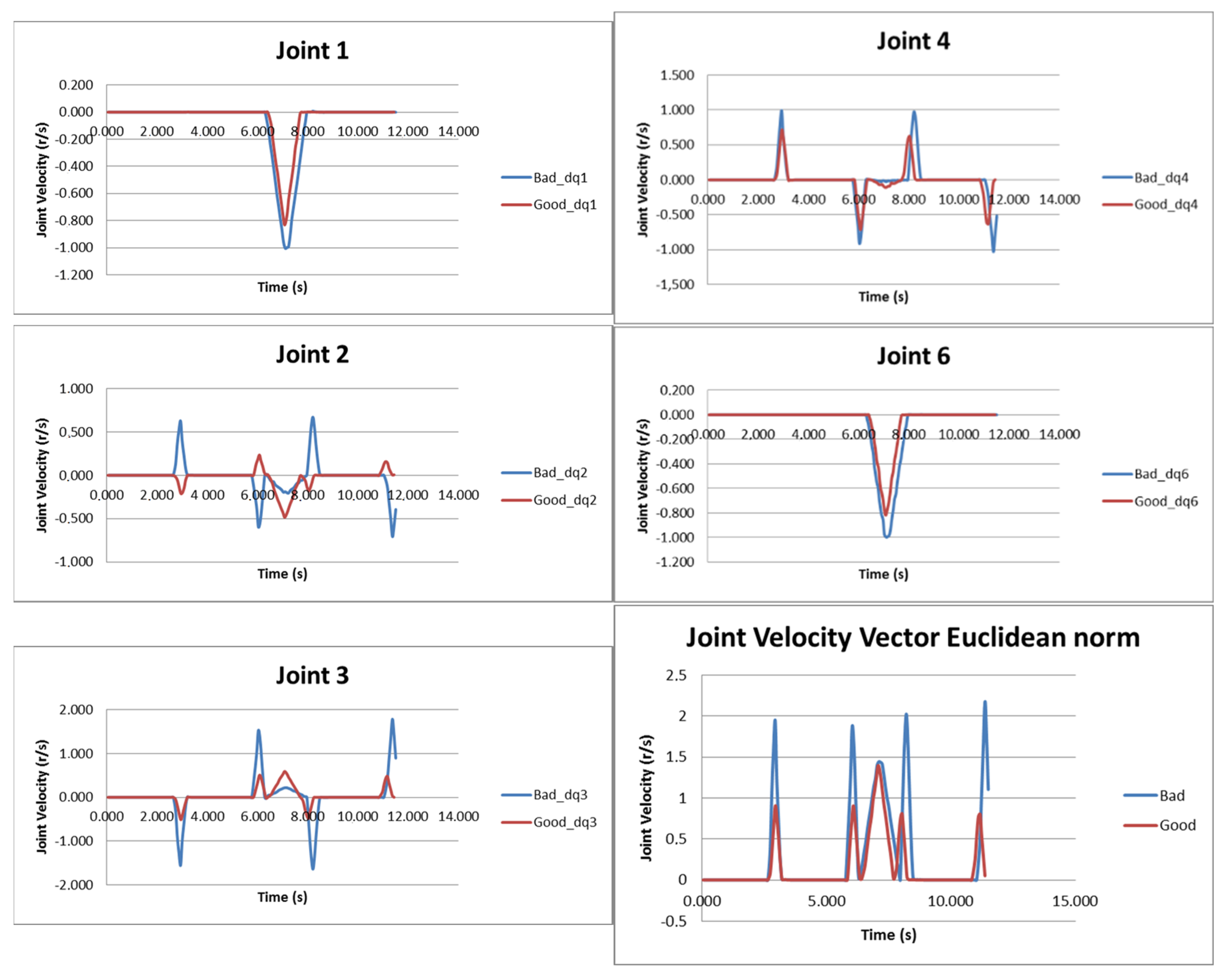
where the pure motion time without grasping and ungrasping time is in the brackets. The resulting graphs of the joint velocities for the first experiment as well as the corresponding Euclidean norm graph are presented in Figure 10 for the cylindrical peg. It should be noted that the graphs for the 5th joint velocity are omitted in both figures, since the 5th joint did not move during task execution.
As shown in Figure 10, the optimal task placement allowed the execution of the task by the manipulator with lower joint velocities (either individually or in terms of the total joint velocity Euclidean norm) while maintaining the same end effector velocities during task execution. This is more evident in the relative graphs for the third and fourth joint speeds where they are significantly reduced (76.5% and 40%, respectively) for the optimal task placement in comparison to the “bad” task placement. The other joint velocity graphs (first, second and sixth joint) present a smaller reduction in the joint velocity for the best task placement (20%, 37.5% and 20%, respectively). The overall joints velocity of the manipulator, as depicted in the graph for the Euclidean norm is significantly reduced for the whole time period of the task execution (28.6%).
5.2. The Path-Following Task

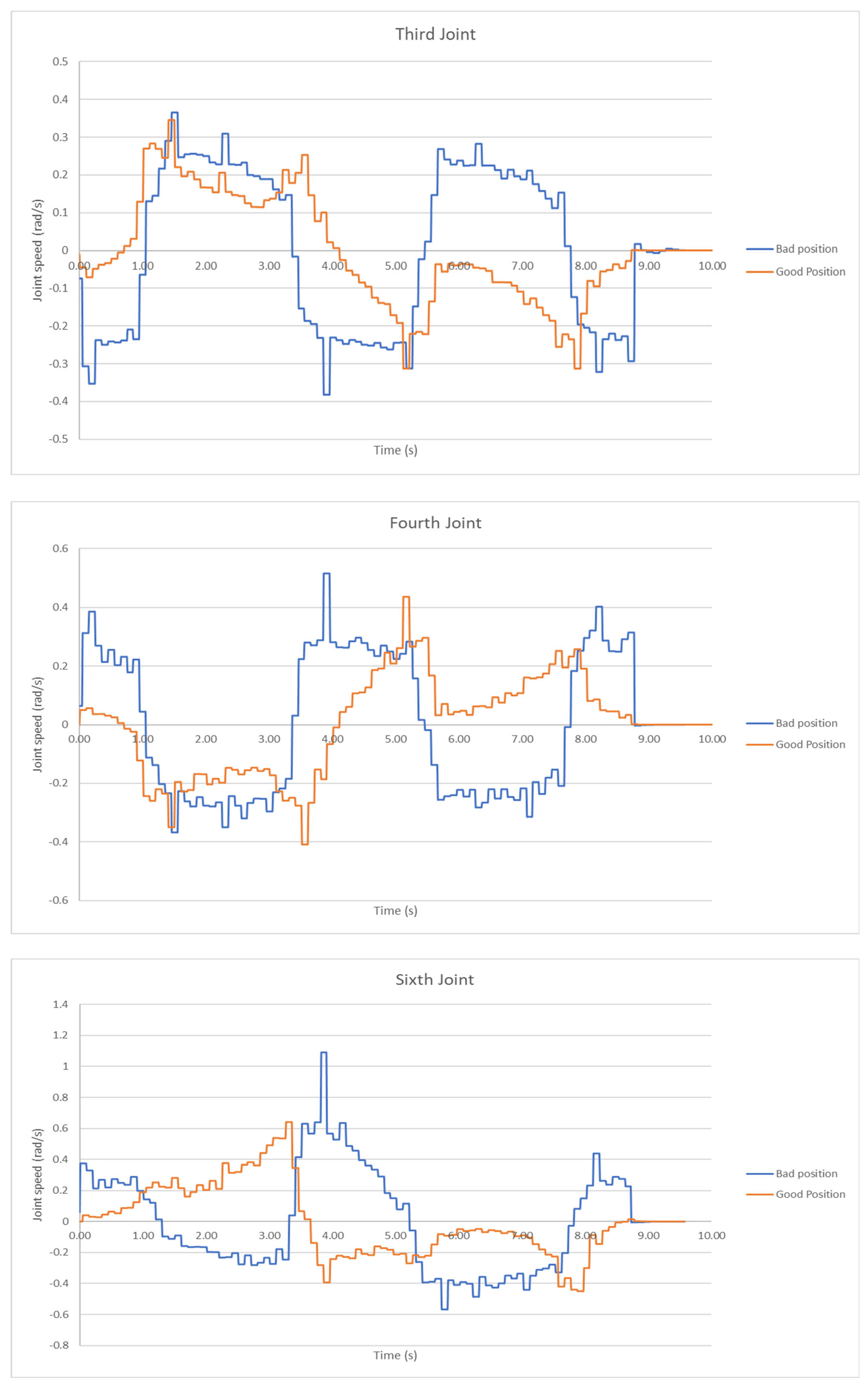
The resulting graph of the joint velocities for each of the manipulator’s joints as well as the Euclidean norm of the joint velocities are presented in Figure 11. The graphs for the fifth joint were omitted as this particular joint was not moved during the task execution.
It can be shown in the presented graphs of Figure 10 that the a joint velocities reduction during the trajectory execution in the case of the task’s optimal placement can be observed. The overall reduction in joint velocities is depicted in the relative graph for the Euclidean norm (Figure 10). Examination of these results allowed for the determination of a reduction of almost 42% with respect to the best over the “bad” task placement. In total, the task was completed in 10 s for both task locations, given the fact that the same end effector velocity was utilized for task execution.

6. Discussion

6.1. Point to Point Task

For both parts of the pick and place task, in the case of the “best” placement of the task, it was observed that lower joint velocities were required by the robot during execution, as opposed to the “bad” placement of the task. With respect to the definition of the MVR, and utilizing a given end effector velocity for task execution, the following conclusions may be derived:
(1)
When the task was placed at the “best” derived location, the robot required smaller joint velocities for all its joints to achieve the same end effector velocity as in the “bad” location. As such, it can be deducted that a most smooth and efficient transmission is evident with respect to joint speeds to end effector velocity. Increasing transmission effectiveness allows for a number of different gains, such as lower loads to the joint motors and reduced energy consumption.
(2)
An increase in the joint velocities at the optimal task location will result in a higher end effector speed and a subsequent reduction in task execution time. This advantage allows the designer to limit the task execution time.
(3)
The envisaged computational and theoretical results were in fact verified through the experimental results provided. As such, it can be deemed that the proposed methodology is valid and cand achieve the set goals. As such, it presents a significant design tool for the design of robotic workcells undertaking kinematic tasks, since the optimal task placement of the latter in the manipulator’s workspace increased the efficiency and kinematic performance of the of task execution by the former. Moreover, the use of the method allows the end user the freedom of choice between task execution under the minimum requirements with respect to joint motor loads and power usage and the utilization of higher joint speeds in order to limit the time required for task execution. Moreover, a balanced selection of the motion characteristics of the robot during tsk execution would allow the simultaneous existence of both gains, albeit to some degree.

6.2. The Path-Following Task

The main find after the examination of the experimental results for the path-following task is similar to that derived for the point-to-point task, i.e., by placing the task at an optimal or “best” location in the manipulator’s workspace allows for an enhancement of transmission efficiency of the joint speeds to end effector velocity, therefore allowing the robot to execute the task with the utilization of smaller joint speeds (third joint excepted).
For the given desired end effector velocity along the trajectory, the reduction in the utilized joint speeds was significant, in the same fashion as with the pick and place task.
In both cases of placement, the end effector prescribed the desired curve with the same defined velocity and orientation, as depicted by the same time span required to perform the task. However, at the best placement, the manipulator utilized lower joint speeds to achieve the desired velocity. As such, this provides two main effects.
Firstly, the designer is capable of significantly limiting the cycle task required for task execution, by increasing the desired end effector velocity. Given the fact that in the “bad” position, the joint speeds are closer to their limits with respect to the respective joint speeds utilized in the best position, there is an increased available range to be utilized in the latter, resulting in a higher end effector velocity.
Secondly, the transmission of the joint speeds in the best position is smoother, allowing for the better prescription of the path by the end effector.

7. Conclusions

A method for the optimal task placement of robotic kinematic tasks in the manipulator’s workspace was presented along with an experimental validation of the method’s results using the UR-5 robot.
The computational results from the presented method were verified by the respective experimental results that showed a significant reduction in joint velocities for the execution of all considered tasks under the same end effector velocity. The optimal placement of the task allows the end user to achieve a wide range of advantages and gains during task execution, where in one end they may choose to execute a given kinematic task with minimum energy requirements and minimum joint motor load, while on the other end they may significantly reduce the task execution time. However, the designer is also presented with the option to achieve both to some degree with a balanced joint speed selection.

Author Contributions

Conceptualization, C.V., A.W., K.M., V.M. and N.A.; methodology, C.V., V.M. and A.W.; software, A.W. and K.M.; validation, C.V, A.W., K.M. and V.M.; formal analysis, C.V., K.M. and A.W.; resources, V.M., K.M. and N.A.; data curation, C.V. and A.W.; writing—original draft preparation, C.V., A.W., K.M. and V.M.; writing—review and editing, C.V, K.M. and V.M.; visualization, C.V., K.M., A.W. and V.M.; supervision, K.M., V.M. and N.A.; project administration, V.M. and K.M.; funding acquisition, K.M. All authors have read and agreed to the published version of the manuscript.

Funding

This research was financially supported by General Secretariat for Research and Technology (GSRT) and the Hellenic Foundation for Research and Innovation (HFRI) (Code: 1184) and by the original research work WZ/WM-IIM/2/2022 funded by the Polish Ministry of Science and Higher Education.

Institutional Review Board Statement

Not applicable.

Informed Consent Statement

Not applicable.

Data Availability Statement

Not applicable.

Conflicts of Interest

The authors declare no conflict of interest.

References

  1. Yoshikawa, T. Manipulability of robotic mechanisms. Int. J. Robot. Res. 1985, 4, 3–9. [Google Scholar] [CrossRef]
  2. Patel, S.; Tarek, S. Manipulator performance measures-a comprehensive literature survey. J. Intell. Robot. Syst. 2015, 77, 547–570. [Google Scholar] [CrossRef]
  3. Asada, H. A geometric representation of manipulator dynamics and its application to arm design. J. Dyn. Syst. Meas. Control. Trans. ASME 1983, 105, 131–135. [Google Scholar] [CrossRef]
  4. Salisbury, J.K.; Craig, J.J. Articulated hands: Force control and kinematic issues. Int. J. Robot. Res. 1982, 1, 4–17. [Google Scholar] [CrossRef]
  5. Dubey, R.; Luh, J.S. Redundant Robot Control Using Task Based Performance Measures. J. Robot. Syst. 1988, 5, 409–432. [Google Scholar] [CrossRef]
  6. Nguyen, Q.C.; Kim, Y.; Kwon, H. Optimization of layout and path planning of surgical robotic system. Int. J. Control. Autom. Syst. 2017, 15, 375–384. [Google Scholar] [CrossRef]
  7. Nektarios, A.; Aspragathos, N.A. Optimal location of a general position and orientation end-effector’s path relative to manipulator’s base, considering velocity performance. Robot. Comput.-Integr. Manuf. 2010, 26, 162–173. [Google Scholar] [CrossRef]
  8. Baizid, K.; Yousnadj, A.; Meddahi, A.; Chellali, R.; Iqbal, J. Time scheduling and optimization of industrial robotized tasks based on genetic algorithms. Robot. Comput.-Integr. Manuf. 2015, 34, 140–150. [Google Scholar] [CrossRef]
  9. Liu, T.; Cavusoglu, M.C. Needle grasp and entry port selection for automatic execution of suturing tasks in robotic minimally invasive surgery. IEEE Trans. Autom. Sci. Eng. 2016, 13, 552–563. [Google Scholar] [CrossRef] [PubMed]
  10. Spensieri, D.; Carlson, J.S.; Bohlin, R.; Kressin, J.; Shi, J. Optimal robot placement for tasks execution. Procedia CIRP 2016, 44, 395–400. [Google Scholar] [CrossRef]
  11. Dharmawan, A.G.; Sedore, B.W.C.; Soh, G.S.; Foong, S.; Otto, K. Robot base placement and kinematic evaluation of 6R serial manipulators to achieve collision-free welding of large intersecting cylindrical pipes. In Proceedings of the ASME 2015 International Design Engineering Technical Conferences and Computers and Information in Engineering Conference, Boston, MA, USA, 2–5 August 2015; p. V05CT08A010. [Google Scholar]
  12. Doan, N.C.N.; Lin, W. Optimal robot placement with consideration of redundancy problem for wrist-partitioned 6R articulated robots. Robot. Comput.-Integr. Manuf. 2017, 48, 233–242. [Google Scholar] [CrossRef]
  13. Valsamos, C.; Wolniakowski, A.; Miatliuk, K.; Moulianitis, V.C. Minimization of joint velocities during the execution of a robotic task by 6 dof articulated manipulator. In Advances in Service and Industrial Robotics, Mechanisms and Machine Science; Springer: Cham, Switzerland, 2018; Volume 67, pp. 368–375. [Google Scholar]
  14. Burdick, J.W. A classification of 3R regional manipulator singularities and geometries. Mech. Mach. Theory 1995, 30, 71–89. [Google Scholar] [CrossRef]
  15. Staffetti, E.; Bruyninckx, H.; de Schutter, J. On the invariance of manipulability indices. In Advances in Robot Kinematics; Springer: Dordrecht, The Netherlands, 2022; pp. 57–66. [Google Scholar]
  16. URScript API Reference. Available online: http://www.sysaxes.com/manuels/scriptmanual_en_3.1.pdf (accessed on 1 December 2020).
  17. Ellekilde, L.-P.; Jorgensen, J.A. RobWork: A flexible toolbox for robotics research and education. In ROBOTIK, Proceedings of the 41st International Symposium on Robotics (ISR) and 2010 6th German Conference on Robotics, Munich, Germany, 7–9 June 2010; IEEE: New York, NY, USA, 2010; pp. 1–7. [Google Scholar]
  18. Wolniakowski, A.; Miatliuk, K.; Gosiewski, Z.; Bodenhagen, L.; Petersen, H.G.; Jørgensen, J.A.; Krüger, N. Task and Context Sensitive Gripper Design Learning Using Dynamic Grasp Simulation. J. Intell. Robot. Syst. 2018, 87, 15–42. [Google Scholar] [CrossRef] [Green Version]
Figure 1. Process of the proposed method realization.
Applsci 12 09352 g001
Figure 3. Side (a) and top (b) faces of pick up and placement bases.
Applsci 12 09352 g003
Figure 4. Best (a) and bad (b) placement of the path-following task, as determined by the GA.
Applsci 12 09352 g004
Figure 5. The optimization process, showing the improvement of fitness function step by step and the steps where the “bad” and best task locations for the path-following task were derived.
Applsci 12 09352 g005
Figure 6. Sensitivity analysis for the results of the best placement of the path-following task with respect to the considered variables: (a) x position, (b) y-position, (c) z-position, (d) orientation.
Applsci 12 09352 g006
Figure 7. The RobWorkStudio environment used to visualize the robotic setup and control the robot trajectory during the task execution. The plugin used for robot control is visible to the right. The task location frames are shown in the visualization.
Applsci 12 09352 g007
Figure 8. Subsystems interactions of laboratory setup in a ‘pick-and-place’ process performed by UR-5.
Applsci 12 09352 g008
Figure 9. (a) Schunk EVG55 gripper with fingers designed, and (b) base with cylindrical and prismatic holes and cylindrical peg.
Applsci 12 09352 g009
Figure 10. Joint velocities for the optimal and “bad” placement of the pick and place task for the cylindrical object.
Applsci 12 09352 g010
Figure 11. Joint velocities during the execution of the path-following task for the optimal and “bad” task placements for end effector velocity 0.2 m/s.
Applsci 12 09352 g011aApplsci 12 09352 g011bApplsci 12 09352 g011c
Table 1. Rules for determining the aspects for the UR-5 manipulator.
Aspect # s i g n E 1 s i g n sin q 3 s i g n E 2
1111
211−1
31−11
41−1−1
5−111
6−11−1
7−1−11
8−1−1−1
Table 2. Optimal location (joint variables values) for the pick and place task (cylindrical object).
qiBp1Bp2Bp3Bp4
θ13.75013.75013.39223.3922
θ2−1.2955−1.3424−1.3995−1.4364
θ30.97121.41911.10131.5315
θ4−1.2464−1.6475−1.2726−1.6659
θ5−1.5708−1.5708−1.5708−1.5708
θ60.18080.1808−0.1771−0.1771
Table 3. “Bad” location (joint variables values) for the pick and place task (cylindrical object).
qiBp1Bp2Bp3Bp4
θ13.67813.67813.19323.1932
θ2−1.1083−1.1888−1.4262−1.4614
θ30.70581.21551.13281.5599
θ41.97341.54421.86421.4724
θ51.57081.57081.57081.5708
θ6−2.6051−2.6051−3.0900−3.0900
Table 4. Effect of the number of intermediate points inserted along the path on the optimization process for the path-following task.
Number of Points Initially Set on the PathNumber of Intermediate Points Set per Path SegmentTotal Computatonal Time Required (s)Best Fitness Function Value DerivedAverage Number of Generations to Achieve Optimal SolutionPopulation Size Used
5043434.980.29528950
5064116.740.290310150
5085014.050.289412250
50107115.670.283413550
Publisher’s Note: MDPI stays neutral with regard to jurisdictional claims in published maps and institutional affiliations.