Review

Research Status and Development Trend of Underground Intelligent Load-Haul-Dump Vehicle—A Comprehensive Review

1
School of Mechanical & Electrical Engineering, Wuhan Institute of Technology, Wuhan 430205, China
2
School of Resource & Safety Engineering, Wuhan Institute of Technology, Wuhan 430205, China
*
Author to whom correspondence should be addressed.
Appl. Sci. 2022, 12(18), 9290; https://doi.org/10.3390/app12189290
Submission received: 25 July 2022 / Revised: 7 September 2022 / Accepted: 12 September 2022 / Published: 16 September 2022
(This article belongs to the Special Issue Perception, Navigation, and Control for Unmanned Aerial Vehicles)

Abstract

:
The underground intelligent load-haul-dump vehicle (LHD) is a product of the deep integration of traditional LHD with information network technology, automatic controlling and artificial intelligence technology. It gathers the functions of environmental perception, autonomous driving and fault diagnosis in one machine and exhibits higher safety and greater efficiency than traditional LHD. Hence, it is a particularly important piece of underground mining equipment for building green, safe and smart mines. Taking the studies about intelligent LHD collected by CNKI and WOS databases from 1980 to 2022 as a sample data source, employing Citespace visual analysis software for key feature extraction from the documents, statistical analysis was conducted to clarify the current research progress and the frontier topics of the intelligent LHD academia in the past 40 years, in relation to the future development trends. The development history and application status of underground intelligent LHD was expounded in this article, summarizing the research status at home and abroad from four aspects: ore heap perception and modeling technology, trajectory planning method of bucket shoveling, autonomous navigation technology, real-time monitoring and intelligent fault diagnosis technology. The demerits and merits of the technologies were reviewed as well, with future developing and researching trends of the underground intelligent LHD concluded.

1. Introduction

Mining is a very important global industry, which is the foundation for industrial development. With the increasing demand of ore raw materials from all over the world and the depletion of shallow mineral resources, following thereupon, the mining scale of underground ore increases greatly [1].
Load-haul-dump vehicle (LHD) is an important and necessary piece of mining equipment, which plays a key role in the transportation of underground ores. Traditional LHD vehicles usually complete ore shoveling, transporting and unloading through manual operation [2,3,4]. However, the following problems always exist [5,6,7,8]. First of all, the production environment is quite harsh. Possible accidents by the underground roadway collapse and the hostile interspace with dust, humidity and noise seriously threaten the health and safety of LHD operators. Second, there are high safety risks upon the driver. Due to underground tunnels normally being narrow and with poor illumination, it is easy for the drivers to experience fatigue while driving, causing accidents. Third, high energy is consumed with low operating efficiency. Since the work efficiency of the LHD mainly depends on the proficiency of the driver, the operating stability of the LHD is unable to be guaranteed. Hence, in order to possibly minimize those issues, how to control and automate the LHDs intelligently have become the main developing trends in this field [9]. In recent years, a large amount of effort has been made on intelligent mining equipment for underground mines, by experts from industry to academia, both overseas and domestically in China. Developed countries, such as Canada, Finland and Sweden, deployed research and application about intelligent and unmanned mining early at the beginning of the 21st century [10]. Various autonomous controlling systems of underground LHDs have been developed successfully and tested in large industrial mines with good results. In China, smart mines have also been constructed gradually with strong technical and financial support from national institutions [11].
Intelligent LHD is a machine system upgraded from traditional LHD by artificial intelligence technology [12], robotic technology [13], information-physics-network technology and image processing technology [14]. It is multi-functionally integrated by remote control, intelligent autonomous operation, intelligent perception and diagnosis, etc. The rapid development of intelligent LHD has really benefitted a lot from the improvements in high-precision positioning and navigation technology. Furthermore, the continuous development and maturity of artificial intelligence (AI) technology also makes significant contributions to it. The intelligent LHD can continue learning new skills to optimize its performance and think like human beings with AI technology [15]. Currently, machine learning (ML) technology has gained wide attention as one of the research directions for artificial intelligence [16,17,18], which has been popularly used in image, speech and other patterns for recognition. Through combining AI technology with automatic control technology, a more effective intelligent trajectory control algorithm has been developed. In addition, the accumulated running data from a real LHD is also conducive to fault prediction and diagnosis.
This article reviewed the research and development status for intelligent LHDs systematically. Four main research directions, such as mine pile perception and modeling technology, bucket loading trajectory planning, autonomous navigation technology and real-time monitoring and fault diagnosis technology, were reviewed in detail separately. The mechanism, characteristics and shortcomings of each technology were discussed as well; the development trend of underground intelligent LHD for the future was also pointed out.

2. The Literature Sources and Statistical Analysis

2.1. Data Source

The output English literature data were extracted from the Web of Science Core collection (WOSCC), while the Chinese data sample was obtained from China’s largest academic journal indexing platform—China National Knowledge Infrastructure (CNKI). Both searches were performed on 17 May 2022 and the detailed data retrieval strategies are shown in Table 1. The valid sample data obtained are: 127 international articles and 158 Chinese articles. It can be seen that the number of articles in Chinese is even greater than that from the international WOSCC database; hence, it is quite important for statistical analysis. However, both source amounts are small, which indicates more attention and attempts should be paid to this topic by industry and researchers in related fields.

2.2. Statistical Method and Result

Data from the above-mentioned database were imported into and analyzed individually by CiteSpace (version 6.1.R2) software, which is a widely used tool for visual exploration of scientific literature provided by SOURCEFORGE software platform in San Diego, CA 92101, United States. The numbers of articles for valid sample data imported into the software were 125 and 142, respectively, as invalid ones were unformatted or information missed. Cluster and keyword co-occurrence analysis for articles in English and Chinese was performed individually and network maps were visually generated, to illustrate the development trend of key technologies and methods worldwide in the field of intelligent LHD as time went by. The results are shown in Figure 1 and Figure 2, respectively. The keywords in the figures mainly come from both the original keywords of the literature and the those expanded based on the subject classification of the journal or database. The font size in the figure represents the occurrence frequency of the keywords. The larger the font, the higher the frequency of the keyword and the more research on it and vice versa. The horizontal position of the keyword represents the recorded year; the more left, the earlier it was paid attention to and studied. The words with a “#” symbol and serial number in the front are the cluster words; the smaller the number, the more keywords are included in the cluster.
The figures can be analyzed as follows:
(1)
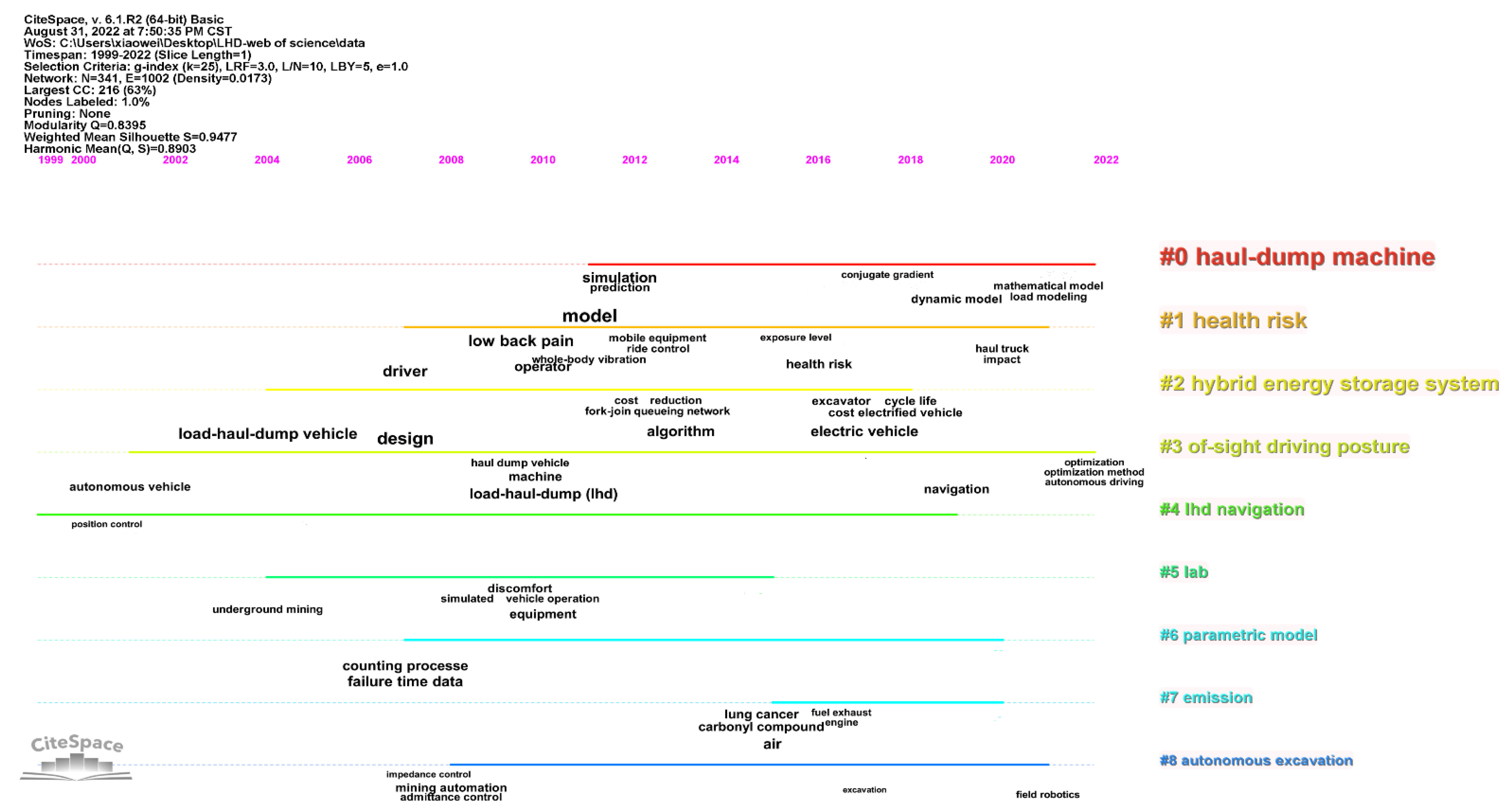
As can be seen from Figure 1, the research in foreign countries about intelligent LHD could be traced back early to the 1990s and was mainly focused in 2007–2022. The keyword co-occurrence was not focused, shown as many scattered words with similar font sizes. If anything was summed up, the research topics about simulation prediction, dynamic model, algorithm, navigation and path tracking were relatively popular.
(2)
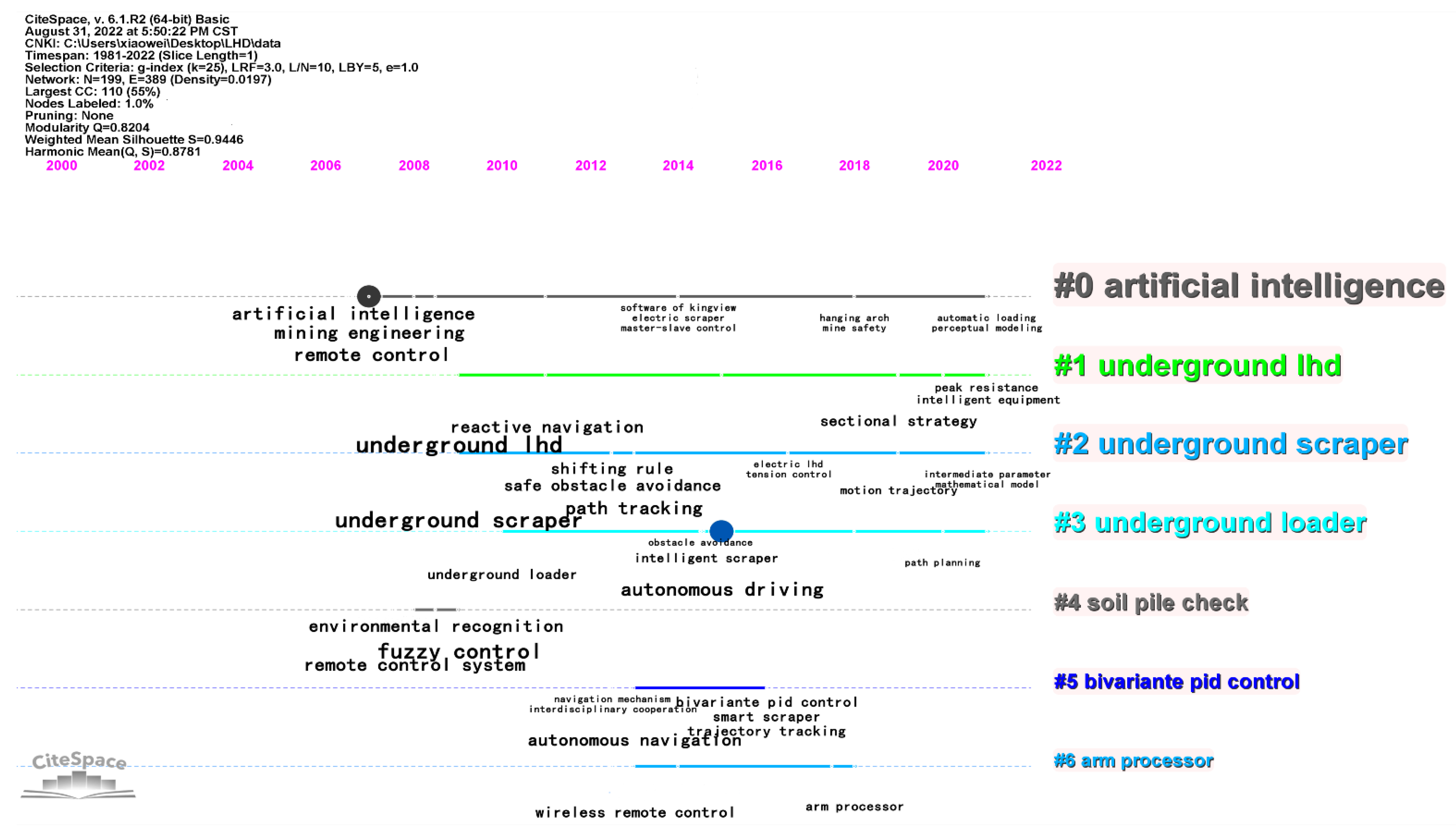
From Figure 2, the research about the intelligent LHD in domestic China was much later than that in foreign countries, beginning from about 2007 and mainly focused in 2009–2021, with hotspots mainly focused on key technologies, such as fuzzy control, remote control, autonomous driving, path tracking, environmental recognition, autonomous navigation and safe obstacle avoidance.
(3)
No matter whether at home or abroad, the research on intelligent LHD was scattered and not extensive. However, it is an undoubtedly important machine and would be one of the hotspots for the intelligent mining industry.

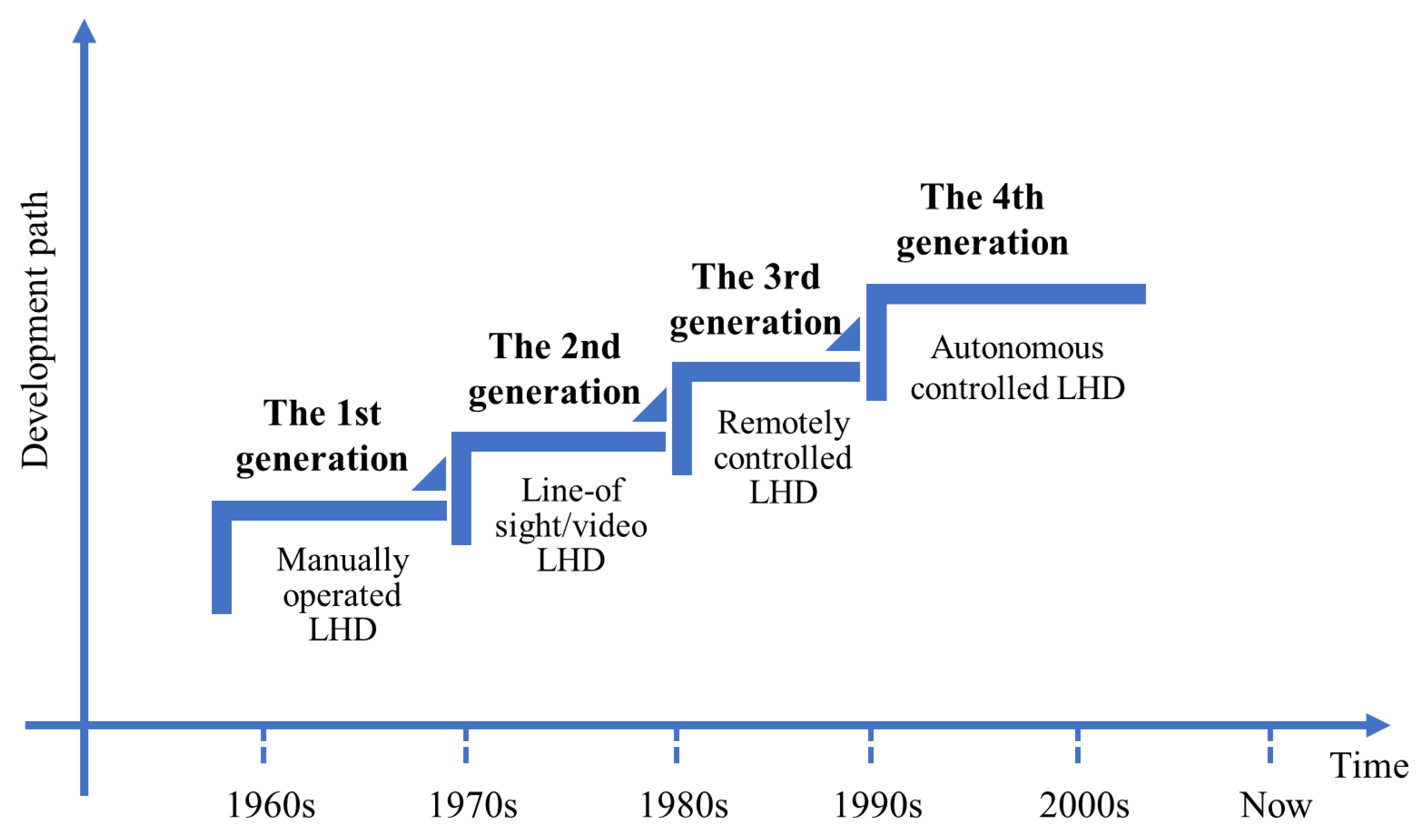
3. Development and Application Status of Intelligent LHD

The first LHD (version ST-5) was traced back to the 1960s, which was developed successfully in the Grandview Mine by the Wagner Company in the United States. Since then, the LHD has been widely used in underground mining around the world due to its high efficiency and flexibility. According to the level of automation control and development history, LHDs can be divided into four generations [19], as shown in Figure 3. At present, the underground LHD belongs to the fourth generation, with functions of intelligent and independent control [9].
Foreign research on intelligent LHDs began relatively earlier; hence, many companies invented LHD autonomous driving, uploading controlling systems with their own characteristics after long-term theoretical research and field tests, such as Sandvik in Sweden, Caterpillar in the United States, Atlas Copco in Sweden, etc. [9].
The Tamrock cooperation in Finland (acquired and owned by Sandvik now) was reported to be the first company in the world to exploit automated mining, which developed the AutoMine system with functions of integrated shoveling, transporting, unloading ores and fault diagnosis automatically [20]. The system was helpful for production increases and maintenance and operation cost decreases. The automatic mining yield of each LHD machine (version LH621) in Finland Pyhäsalmi Mine was improved greatly to 300,000 tons per year after being equipped with the AutoMine system. Both the utilization rate of equipment and the output of the entire mine increased significantly [21]. Canada Kidd Creek Mine extended the effective working time of four LH514 LHDs from 12 h to 15 h and increased the production capability by 50% accordingly, after being equipped with four sets of Sandvik company’s single remote-controlling intelligent LHD system [9]. In 2018, Sandvik innovatively invented another new generation of unmanned underground LHDs, which made it possible to shovel, transport and unload ores totally automatically during the whole process. The machine passed through a complicated glass maze successfully with the help of equipped laser scanners, gyroscopes, odometers and angle sensors [22]. However, there has been no industrialization application yet [23]. The MINEGEM system was a new autonomous control system for a new generation of LHDs, jointly developed by Caterpillar and DAS in Australia in around 2004. Remotely controlling the LHDs on the ground to perform operations, such as shovel, transport or unload ore, could be attained with this system, through the cooperation of airborne computers, sensors, wireless networks, etc. This system was adopted by the Malmberget iron mine in Sweden and protected their operators from the dangerous underground environment with a remote ground comfortable operating room. Moreover, the system ran quickly and greatly improved the production efficiency by about 25%; the effective operating time was extended by 4~6 h as well [24,25]. In later years, Caterpillar further developed the ancillary software for this system, named Auto Dig, to automatically control the whole shoveling, transporting and unloading process. Through recoding a large amount of operation data by experienced drivers from a variety of buckets for a variety of given ores during loading cycles, the loading model could be established and optimized by computer and the fully autonomous operation was finally realized.
Atlas copco in Sweden is another famous company for intelligent underground LHD research and development. In 2006, it modified the ST. 1010 underground LHD with a reactive navigation system to an autonomous machine together with researchers from the University of Urebro, which was proved to be practical in the Kvarntorp Mine through automatic tests. At the end of 2007, its LHD automatic control system was applied to the ST-14 underground scraper and the automation experiment was carried out successfully in the Kemi mine in Finland [19]. The machine was equipped with three cameras, two in the front and one at the back. In addition, three additional cameras were reinstalled in the loading and unloading zones on the roadway as a supplement. Through scanning the way in the front roadway in 35 m by the laser mounted on each side of the vehicle, the real-time precise relative position of the ST-14 to the wall could be acquired [23]. After combining the ultra-precision steering algorithm and the speedometer, the operator could determine the precision potion of the machine in the roadway. Recently, Atlas company developed its own Scooptram automation technology, a semi-autonomous control system, with the goal of protecting human safety, improving machine performance and flexibility. The main advantage of the system is that the operation system could be maintained easily in control and integration with other systems without exposing the operator to the unsafe environment. Moreover, no other infrastructure support was needed and it could work even during blasting operation [26].
In addition to the main three companies mentioned above, there were also many other companies or research institutes investing finance and effort on this topic. A German manufacturing company of underground mining equipment called PAUS developed a new version (Tiger 300D) of underground LHD, based on the video remote control technology of the NAUTILUS company. Two cameras were set in front of the loader and another in the back. The cameras acquired and transmitted the image data to the display screen of the remote-control box firstly; the machine was automatically slowed down if someone was found standing on the road, even stopping if necessary. The device not only expanded the driver’s vision, but also could be controlled through wider-range radio and was much safer. Furthermore, it could be either remote controlled automatically or manually controlled [27]. The Commonwealth Scientific and Industrial Research Organization (CSIRO) and the University of Sydney in Australia cooperated in the research on the special sensors for autonomous control of the LHD on the mount ISA. The sensors suitable for the underground environment were picked out through collecting a large amount of data from the sensors installed on the underground LHD [28]. Afterwards, CSIRO further researched the development of autonomous control of underground LHDs, with financial support from AMIRA, mainly focused on the positioning technology based on the dead reckoning method. The autonomous navigation system integrated from the underground electronic map data and the laser scanner sensor and, finally, the autonomous control of the driving process and identification of the signs and blocks on the road could be realized [29]. Vielle Montague in Sweden also developed a remotely operated and navigation-enabled LHD; autonomous controlling tests were carried out in the Zinkgruvan zinc mine. The navigation and autonomous driving could be attained by tracking the white lines coated on the roadway roof with a camera. The maximum running speed was 8 km/h. During the 9-month test period, a total amount of 1200 buckets of ores was transported [30].
China’s research on the autonomous control system of underground LHDs started relatively late and has gone through four stages of introducing from abroad, cooperative manufacturing, independently developing, innovatively creating and developing [31]. During the “Eleventh Five-Year” period (2006~2010), Beijing General Research Institute of Mining and Metallurgy conducted a research program on “Accurate Positioning Technology of the Underground Mining Equipment and Modeling Method for the Intelligent Unmanned Underground LHD” under the “863” goal-oriented project, together with the University of Science and Technology Beijing [32].
They constructed an underground electronic map through the vectorization of engineering drawings using GIS software and the position display and alarm of the scraper were basically realized by combined technologies of the laser scanner system [33], track estimation and beacon correction at the same time [34]. As a result, the underground LHD autonomous navigation and control technology were initially developed in China and the model for the unmanned underground LHD was established [35]. Later on from the “Twelfth Five-Year Plan” period, the two institutes cooperated continuously on the program on “Underground Intelligent LHD” under the “863” theme project. The program team explored and researched deeply the autonomous driving and unloading technologies of the LHD [36] and realized the field operation in the line of sight or by remote control in the Zhangzhuang Mine, Fankou Lead-Zinc Mine, Dayingezhuang Gold Mine, etc. [4,8,10].
At present, some underground mines in China are testing and promoting fourth-generation underground fully automatically operated LHDs gradually, in order to realize unmanned mining operations [9].

4. Autonomous Shovel Technology

4.1. Rock Pile Identification and Modeling Technology

The underground intelligent LHD identifies the ore pile and obtains information, such as its shape and outline, through equipment, such as cameras or laser scanners, in the first step, creates a three-dimensional model of the ore pile secondly and then transmits it to the bucket excavation trajectory planning system to assist it in the process for planning of optimal mining trajectories. Therefore, the perception and modeling of the ore pile is a significantly decisive step to realize the autonomous shoveling and loading with the LHD [5,9].
There is extensive research on mine pile sensing technology at home and abroad, which can be mainly classified into two categories by sensing mechanisms: mine pile identification based on image sensors and that based on distance sensors [5].

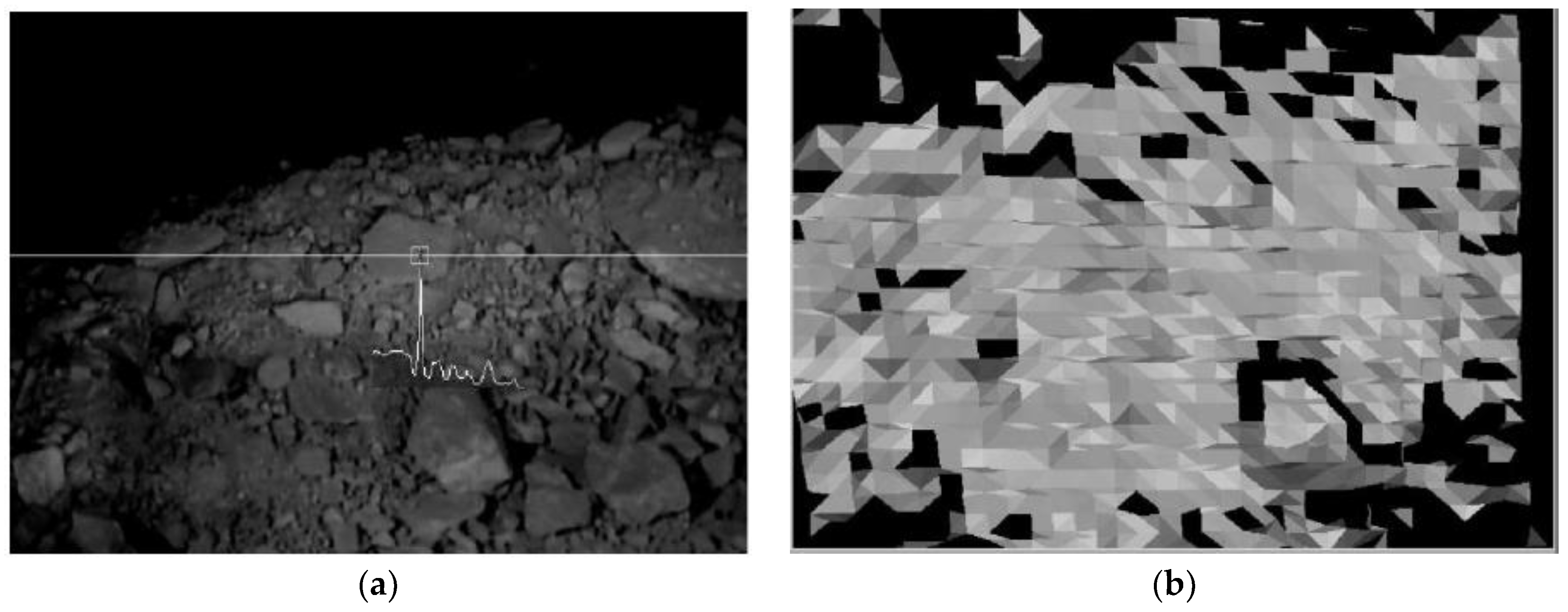
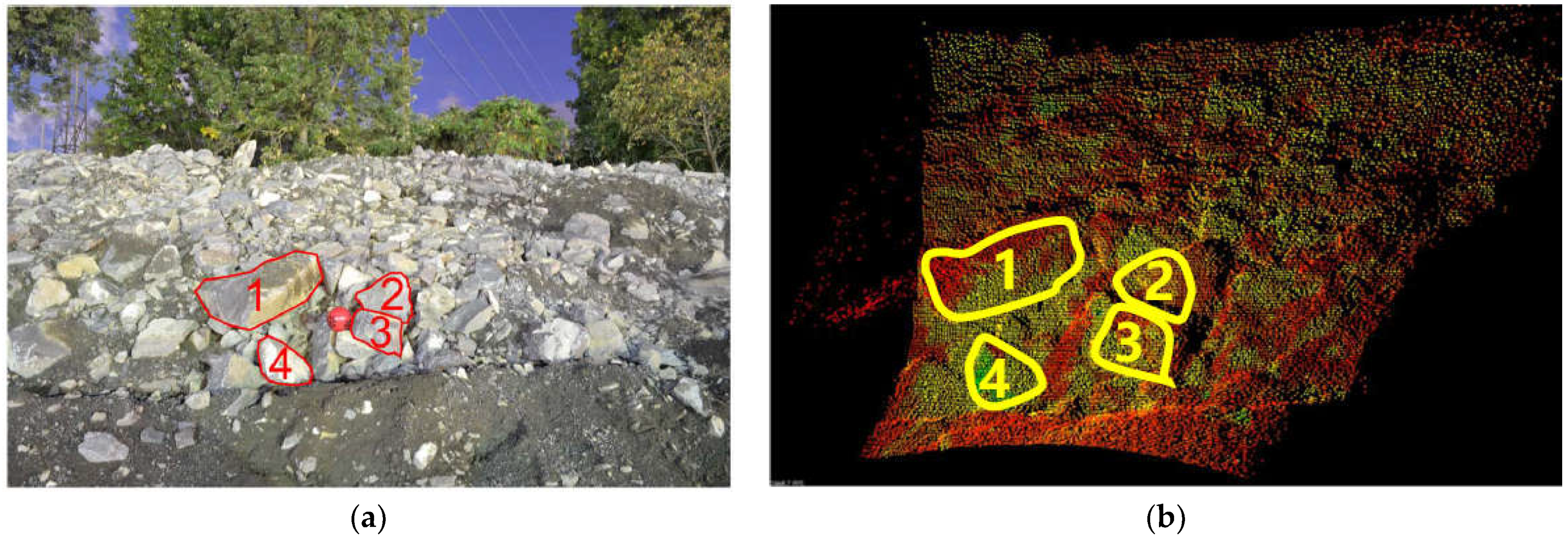
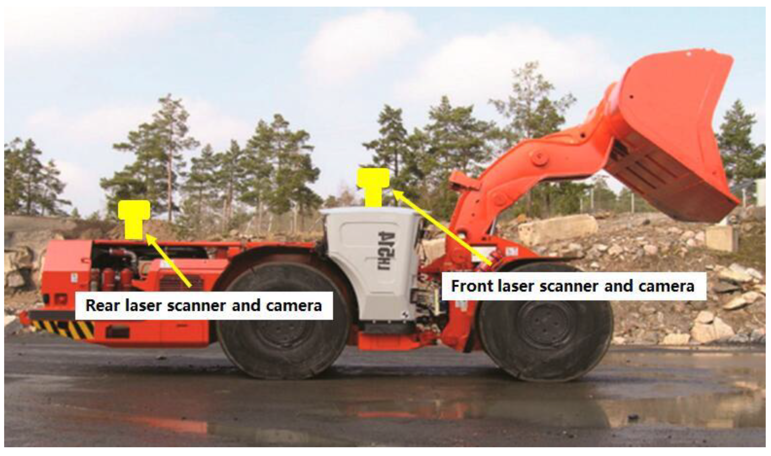
4.1.1. Image Sensor-Based Rock Pile Identification

The image sensor is the core component in cameras. It converts an optical image on the photosensitive surface to electrical signals through photoelectric cells and obtains information consistent with human perception under good illumination conditions [37]. According to the number of cameras, the vehicle camera system can be divided into monocular camera, binocular camera, depth cameras (RGBD) and panoramic camera [38]. The utilization of monocular camera faces contradictions in ranging and distance. The wider the perspective view of the camera, the shorter the length of the accurate distance that can be detected and the narrower the angle of view, the longer the distance detected. As a result, when it is used on the scraper to perceive the ore pile, it can only obtain its information from a limited certain angle, which makes it difficult to construct the 3D model for the ore pile. The binocular camera system can cover different ranges of scenes through different cameras [39] and obtain comprehensive information about the ore pile. However, the process for comprehensively extracting information of the ore pile from multiple angles and multiple pictures is always extremely complicated to calculate, with high system requirements, which makes the 3D modeling construction quite difficult and slow.
The University of Southern Queensland produced an LHD model with a ratio of 1:5 to the physical machine. It is constituted with a CCD camera, a PC with image acquisition hardware and structured lighting form a vision system together and was successfully applied on 3D model establishment for rock piles [40]. The Western Mining Resource Center in the Colorado School of Mines in the United States conducted a project about LHD automation research. They collected mine production images with digital cameras, then filtered and interpolated the images and established a 3D curved surface model finally. This is helpful for the enhancement of the LHD’s autonomous controlling and running capability as feedback. According to the experimental results, 3D models could be built even in a dark environment, but failed to be updated in real-time. An example to illustrate the image-sensor-based rock pile identification and 3D modeling process is shown in Figure 4. It proved that even for images obtained from pretty dark sites (Figure 4a), the 3D model was established successfully (Figure 4b) [41].
The advantage of a 3D ore pile model based on an image sensor is that, after obtaining the information of the ore pile through the image sensor as images, it can quickly build a 3D model through an image processing algorithm and update the model in real time. However, when the light is insufficient or the camera is blocked by dust, the image obtained would be not clear enough, possibly resulting in failure of the 3D mine pile model establishment through a single view [5].

4.1.2. Rock Pile Identification Based on Distance Sensor

The distance sensor mainly obtains the size information of the object by detecting the time interval from the light pulse emission to object reflection [42].
Carnegie Mellon University developed the first large-scale excavation and loading automatic system (Autonomous Loading System, ALS), which uses laser scanners to scan the to-be-excavated area for planning of the optimal excavation location. However, this system is mainly favorable for the excavation of soft-soil ore piles; no research has been carried out on the excavation of large hard ore piles [43].
The particles in the ore pile are always irregularly shaped without uniform sizes, since they are usually obtained after blasting the mine. Therefore, in order to avoid shovel loading failure or damage to the scraper, pretreatment must be performed first, meaning large ore blocks in the ore pile should be crushed or removed if they exist [44,45,46]. McKinnon C. et al. generated point cloud images with a rock pile recognition algorithm based on the images from the time-of-flight camera successfully. This technology realized good recognition of ore piles without the help of other sensors, which is beneficial for the extraction of bulk ores from irregular heap surfaces, as demonstrated in Figure 5. It can be seen that point cloud images could be generated based on the original photo by the camera, as expected. Moreover, the sampled lump ores, numbered as 1 to 4 in the point cloud image (Figure 5b), could be recognized clearly and matched quite well with those in the original one (Figure 5a) [47].
The advantage of mine pile identification based on distance sensors is that it can completely collect the mine environment information and create a 3D mine pile surface model quickly. However, only the surface information on the ore pile can be acquired through the distance sensor and the texture information of the surface is easy to lose [5]. Moreover, the modeling speed will be slowed down for high-density data processing, which is a result of ore pile scanning from multiple perspectives.
To sum up, a single type of mine pile identification based on either image sensors or distance sensors has its drawbacks. Therefore, the cooperation of both sensors on ore pile identification and modeling technology would be a considerable research direction for future underground intelligent LHDs. As the example, shown in Figure 6, both types of sensors are adopted as two sets of laser scanner and camera (one in the front and the other in the back) on the LHD to collect information of the ore piles. After data recognition and integration, the 3D heap model for even dark and dusty underground environments can be quickly established. The model can also be updated in real time with changes in the field conditions [48].

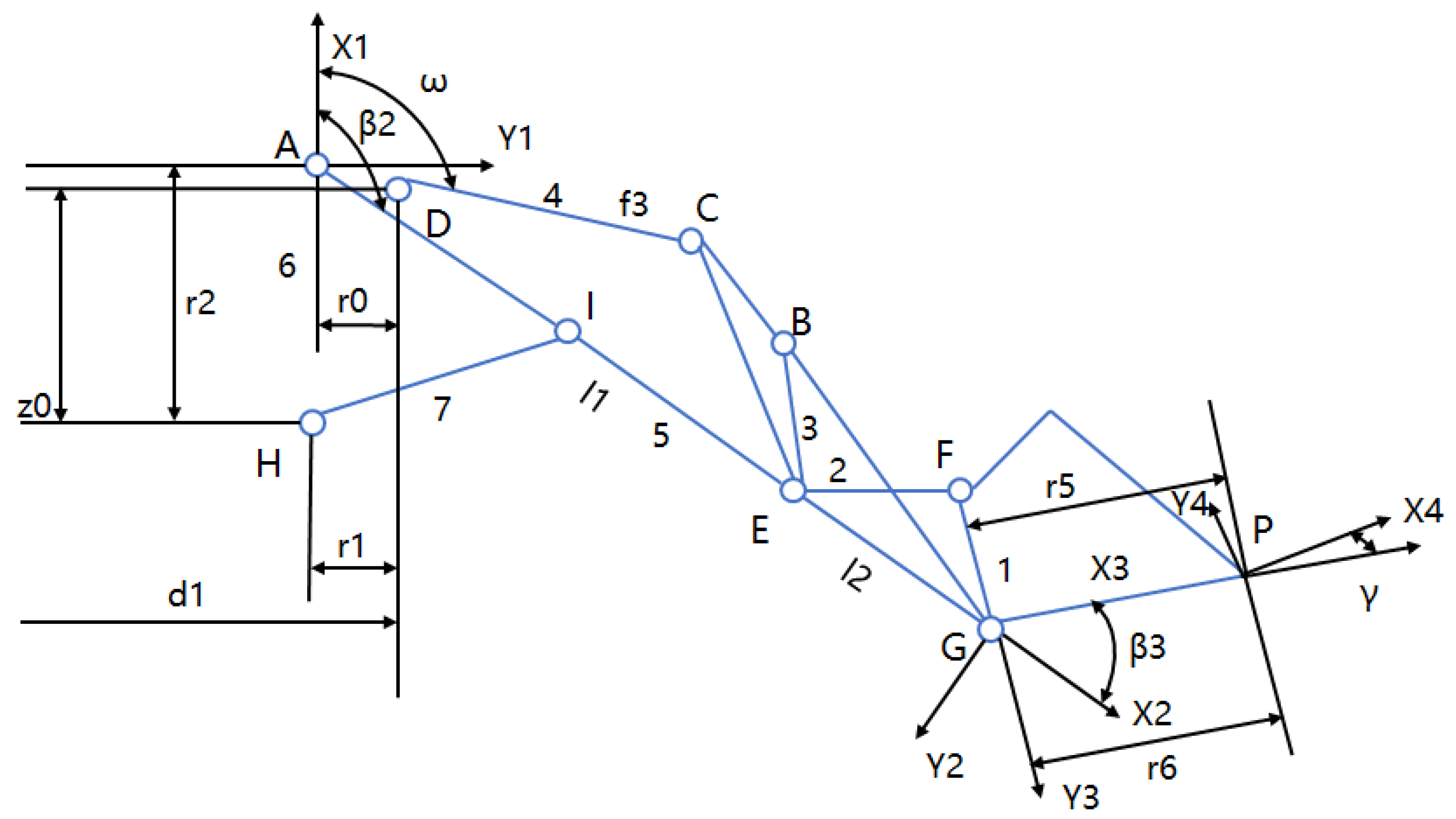
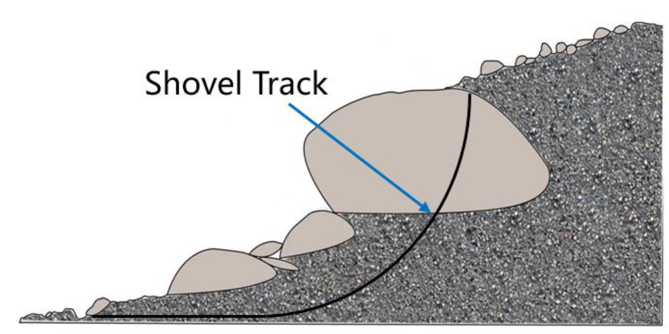
4.2. Shovel Trajectory Planning

After establishing an accurate three-dimensional ore pile model, the starting position for ore shovel loading will be independently determined and the optimal trajectory will be planned as well, theoretically based on the maximization of loading efficiency and minimization of energy consumption [50]. Based on the controlling model, bucket loading trajectory planning methods can be divided into the one determined by resistance force and the other directed by self-learning.

4.2.1. Resistance Force Determined Trajectory Planning Method

In a joint project by Russian scholar Mikhirev and the Minsk Machinery Research and Production Association, which was mainly about the development of the open-pit mining automatic loader, the calculation method of the effective trajectory for the excavator bucket was firstly studied based on mechanical control [51]. In order to shovel the materials better with the bucket, it is rather necessary to accurately predict the digging resistance from the obstacle. Obermayr et al. [52], from Kaiserslautern University of Technology, Germany, predicted the excavation resistance of a slab excavator in unbonded granular material, excavating using the discrete element simulation method and the accuracy of the results was verified by experiments. Coetzee, from Stellenbosch University in South Africa, simulated and analyzed the bucket excavation process using the discrete element method simulation platform, but the predicted excavation resistance was found to be smaller than the actual value from experiments. In addition, the excavation resistance changing trends were almost the same in the entire excavation time domain [53,54].
Since the shape and size of the ores are inconsistent after blasting, the resistance from the ore blocks on the scraper will change during the shovel loading process. Therefore, when establishing the resistance model, it is necessary to take the change in the shape and size of the ores into consideration. Guiyu Lin et al. [55], from Northeastern University, counted the rock materials with different particle sizes after blasting through discrete element and simulated their excavation process based on the actual prototype, then predicted the excavation resistance under several complex working conditions. It was found that the results from prediction were quite close with the resistances under actual situation. Xiaobang Wang [56], from Dalian University of Technology, established a rapid online excavation trajectory planning method for the mining shovel, based on a dynamic excavation resistance prediction model, especially for complex ore piles. The experimental results showed that the running accuracy of the trajectory planned by this method can be improved by more than 14%, compared with the traditional mining resistance model, and the energy consumption was reduced by 8.86%.
Although the excavation resistances predicted by the above method are close to those under actual conditions, it cannot be said that the predicted situation can fully explain the actual site, since the possible accidents, such as collapse or landslide, would happen during the actual excavation process. Hemani [57] believed that the material excavation could not be realized but only guided through the resistance model preset by the mathematical formula. Hence, he proposed to adjust the excavation trajectory according to the real-time magnitude of the resistance during the excavation process. W. Richardson-Little [58] presented a rheological method for simulating the interaction force between the soil and bucket. Then, under real conditions, the excavation trajectory of the excavator bucket could be controlled and adjusted through detecting the force on it. Meng Yu et al. [49] established a mechanics feedback model for the bucket based on Coulomb earth pressure theory. With 100% full bucket rate as the prerequisite, the insertion depth was optimized to minimize the energy consumption and the optimal bucket trajectory was finally determined. Marshall J.A. et al. [59], from Carlton University in Canada, proposed a velocity-based admittance controller for the first time according to the characteristics of the scraper hydraulic cylinder induction force during the excavation process. Field tests were also conducted on the Atlas Copco scraper and proved that the shovel loaded more efficiently than manual operation. Chaozhong Yin et al. [60], from University of Electronic Science and Technology of China, established a manipulator model system, which adopted the method of intelligent drag reduction, inserting a shovel on the basis of the minimum energy consumption trajectory. The bucket was stressed less, the energy consumption of the process was effectively reduced and the production was significantly improved under this planning method. The corresponding calculating formula for the uprise velocity for minimum energy consumed trajectory is listed below as Equation (1).
V p u = l 1 + l 2 s i n β 2 β 2 + [ r 5 sin ( β 2 + β 3 ) + r 6 cos ( β 2 + β 3 ) ] ω  
in which, Vpu is the uprise velocity component of the bucket tooth point P, l1 is the boom length, l2 is the pull rod length, r5 is the depth of the bucket, r6 is the vertical distance between the tooth point and the bottom of the bucket, ω is angular velocity of the bucket and β2 and β3 are the second and third velocity vectors of motion pair, respectively. For a better understanding of those parameters, the manipulator model system is graphically described in Figure 7, in which the blue lines are a simple profile for the reverse six-bar linkage mechanism, with letters A–G representing the movable mechanical joints; the black lines are just for annotations.

4.2.2. Self-Learning-Guided Trajectory Planning Methods

With the development of artificial intelligence technology, many scholars have tried to solve the complex and changeable problems during the shovel loading process of LHD by applying learning methods. Scholars from the University of Arizona [61] applied fuzzy logic control to perform mechanical mining in unstructured and unpredictable environments for the first time and combined fuzzy logic with neural networks to simulate robotic autonomous mining experiments. Lever et al. [62] developed an automatic dig control system (ADCS) based on the combination of both a behavior-controlled and fuzzy-logic-controlled model. Tests were conducted on a Cutler wheel loader and found to excavate comparably to manual operation but required longer mining time. G. J. Maeda et al. [63] proposed an earthwork excavation control method for the excavator based on a combination control of iterative learning and impedance. Siddharth Dadhich et al. [64] proposed an autonomous mining method based on reinforcement learning (RL), which is suitable for the mining of different pile types and ore shapes. This method worked well with steady loading weight, cycle time and fuel efficiency [44]. Heshan Fernand et al. [65] advanced an iterative learning-based admittance control algorithm, which could automatically update the control parameters according to the target bucket filling weight. It was verified to be effective for both fragmented rock and gravel shoveling after field testing with a 14-ton scraper. In addition, the performance on the fragmented rock piles was better than that on gravel piles.
The self-learning-guided shovel trajectory planning method has obvious advantages when working in the uncertain underground roadway. Through interactive learning about the environment, the bucket trajectory planning can be better completed. However, a large amount of data and long time of study are required for training to implement good trajectory planning.
In general, the shovel loading trajectory needs to be planned according to the actual real-time loading conditions, either guided by resistance force or self-learning. The ultimate aim is to excavate successfully with optimized shovel time and energy consumption. If the loading trajectory is planned improperly, as shown in Figure 8, the shovel fails as the lump block is too big.

5. Autonomous Navigation Technology

Autonomous navigation technology refers to the technology that the scraper can automatically identify the environment through its own various sensors under unmanned control after ore shoveling and then automatically plan and complete the best driving path in the roadway [66].

5.1. Positioning Technology

The positioning technology for the underground intelligent scraper refers to the determination of its position in a two-dimensional coordinate system and its own attitude as well or it can also be expressed as the relative position of the scraper to the coordinate of a known location (beacon point) in the underground tunnel. Thus, positioning technology is the basis for autonomous navigation of LHD. GPS-based autonomous positioning technology is known to be popular in many fields, but as the GPS signal is too weak in the underground roadway, other methods need to be found for scraper positioning [67]. At present, there is much research on the LHD positioning technology at home and abroad, mainly as the dead reckoning method, inertial navigation technology, ultra-wide band (UWB) positioning technology, visual positioning technology and information fusion positioning technology, etc. [68,69,70].
(1)
Dead reckoning method
The basic principle of the dead reckoning method is with known initial coordinates of the scraper, collecting the information of heading angle, speed and time using the sensors installed on the scraper (such as heading gyro, speedometer, odometer, etc.) and calculating the data for the current position of the shovel [71]. This method has good accuracy and low cost for short-term positioning, but has accumulated errors for long-term positioning estimation, which need to be corrected by correction techniques [68,72].
(2)
Inertial navigation technology
The inertial navigation system is a completely independent system that does not rely on external information, but obtains the information of the speed, position and attitude of the vehicle by its own inertial components, such as gyroscopes and accelerometers [68]. Although the inertial navigation technology exhibits good concealment, it has advantages, such as being affected by neither natural, man-made factors nor external electromagnetic interference, and there will be inevitable accumulative errors after a long-time server. In order to improve the absolute accuracy of the system, other auxiliary positioning sensors are necessarily installed. To be specified, the cost for the equipment in this system is reported to be quite expensive [73,74].
(3)
UWB Positioning
UWB technology locates in real time the vehicle through building a base station in the roadway, obtaining signals between the base station and the vehicle tag, then attaining the real-time location information of the tag. This method is reviewed to be insensitive to channel fading, showing high positioning accuracy and low system complexity [75,76]. To position the accurate two-dimensional location of the vehicles, Chehri A. et al. [77] conducted tests to collect the distance signals and position the tags, especially for narrow-long underground coal mine roadways, through UWB technology and TOA algorithms, respectively. It was found that this method was proved to show higher positioning accuracy than regular methods in both visual and non-visual distance. However, in UWB positioning technology, the location information of at least three base stations needs to be received for calculation about the tags’ location in the targeted area zone. Since the underground tunnels are always long and narrow, multiple base stations must be constructed and high cost would be consumed for higher positioning accuracy [67].
(4)
Visual Positioning
Visual positioning technology refers to collecting the surrounding environment of the roadway by cameras or other visual sensors, setting, identifying and tracking special route markers by the scraper, analyzing the signals and finally obtain the location information of the scraper. Weiss L.E. et al. [78] proposed a form of visual serving control, which can overcome uncertainties in the calculation models (including robots, vision systems and environments) and improve the accuracy of visual positioning or tracking. Iu S. et al. [79] pointed out that estimating the target’s moving direction and structure through the maximum likelihood estimation method was found to be quite accurate. Wu Di et al. [75] proposed a calculation method of minimizing the error of photometrics based on its weight of different texture areas, to improve the matching accuracy for images with dim and noisy points obtained from a dust-filled underground roadway.
In general, the visual positioning technology is accurate in location, but as the scraper works in unique underground scenes, it still faces challenging problems, such as environmental features being insufficient, roadways being too dusty and lighting conditions varying too much, etc. Hence, how to make the system operate stably and long term will be a key problem to be solved in the future.
(5)
Information Fusion and Location Technology
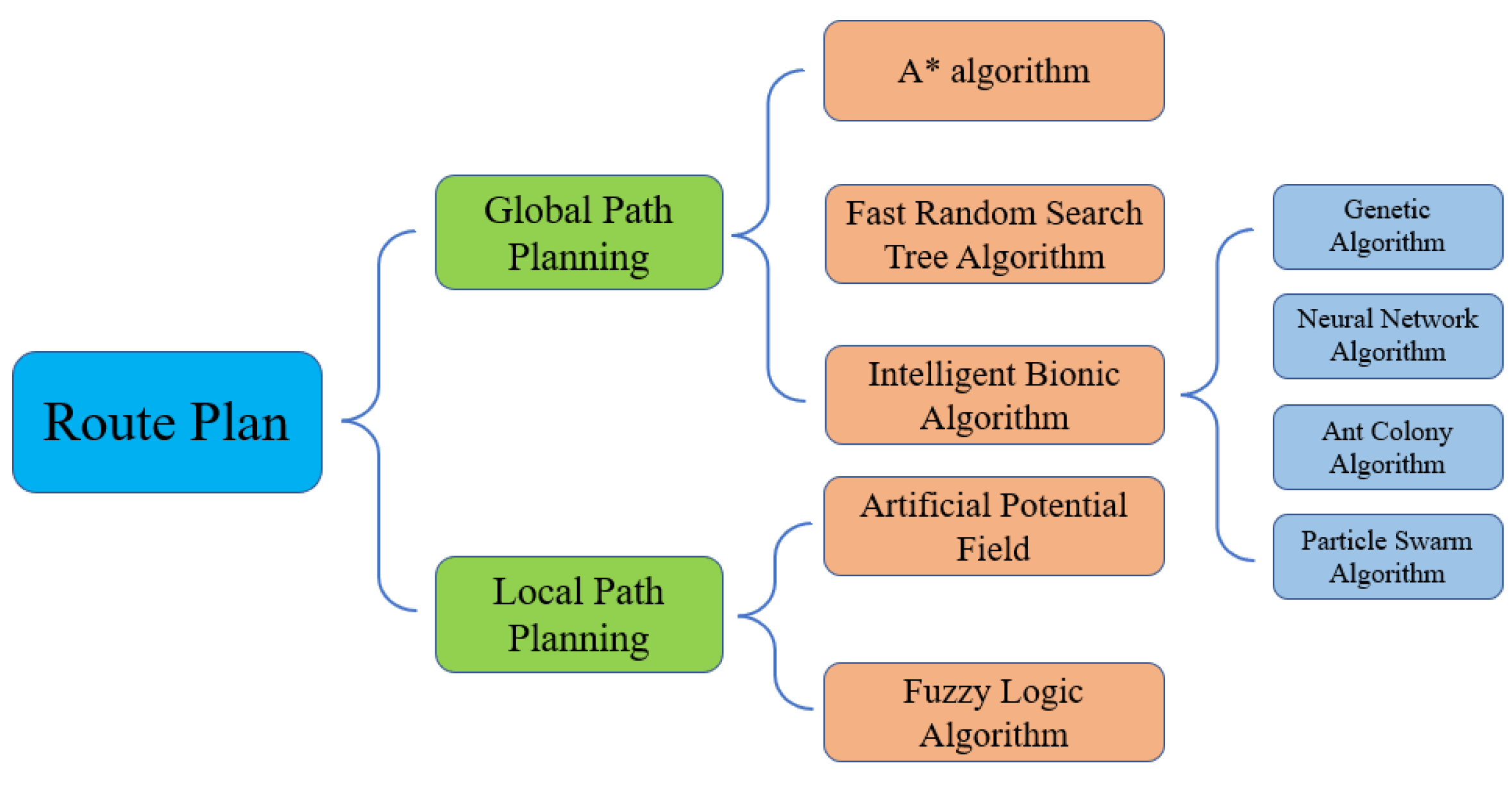
Single-positioning technology usually has certain limitations. Therefore, various information from different positioning technologies can be integrated to locate the scraper and improve the positioning accuracy. MaKel A.H. et al. [80] applied a positioning method combining dead reckoning and laser scanning positioning and determined the position and driving direction of the scraper by the articulation angle sensor, odometer and gyroscope. The result from dead reckoning was corrected by the scanning data of the roadway wall obtained through two laser scanners. The accumulated error was significantly improved compared to the ordinary dead reckoning method and the installation of other auxiliary equipment was avoided in the roadway. Wang B. et al. [81] optimized the location and navigation algorithm based on the combination of the dead reckoning positioning and laser scanning. The simulation results showed that this method can improve the accuracy and robustness of the operating system. Chi Hongpeng et al. [82] and Jiang Yong et al. [83] combined the information obtained from both the heading gyroscope and the laser rangefinder by Kalman filtering algorithm based on a multi-sensor information fusion model and the heading angle of the scraper was accordingly determined. Shi Xiaojie et al. [67] proposed a positioning system, which combined the UWB and laser ranging methods in the view of the long and narrow characteristics of underground tunnels and the high cost for UWB positioning systems. Skoczylas A. et al. [84] integrated the inertial measurement unit (IMU) and dynamic time warping (DTW) algorithms to locate the underground mine LHD and it was found to have good robust performance.
The characteristics of various positioning technologies are listed for better comparison in Table 2. To sum up from Table 2 and the above-reviewed text, each single-positioning method has its own advantages and disadvantages. Even though the limitations of a single-positioning technology can be overcome and the positioning accuracy can also be improved to a certain extent when various technologies are jointly applicated in different ways, the technology still faces the problems of high cost for the equipment and complexity for the calculation. Hence, how to improve the adaptability of the positioning technologies and cut costs are the key scientific issues to be considered in future research at home and abroad.

5.2. Path Planning

Path planning technology is important for autonomous navigation of underground intelligent LHD [3]. When the scraper finishes shoveling the ores, there must be a planned collision-free path from the starting point to the destination, through which the distance is short, the transportation is efficient and energy is saved. According to the degree of access to environmental information, they can be divided into global path planning methods and local path planning methods [31], as shown in Figure 9 in detail.

5.2.1. Global Path Planning

Global path planning means searching an optimal route between the origin and the terminal for the underground intelligent scraper to drive autonomously in a known environment.
(1)
A* algorithm
The A* algorithm is a heuristic search algorithm, which guides and determines the search direction, mainly through an evaluation function [86]. As long as the optimal distance from the node to the target point is determined, an optimal path must be obtained [87]. However, it is necessary to conduct a traversal search around the nodes on the path to optimize the path and save cost, resulting in large calculation amount, poor real-time performance and long operation time. Moreover, as the number of nodes increases, the algorithm search efficiency decreases [12]. In order to improve the efficiency for the optimal path searching and reduce the searching time, Zheng et al. [88] used a jumping point search method based on the A* algorithm and introduced the angle evaluation function into the cost function in the A* algorithm. The number of inflection points on the path obtained by the combined method was minimized compared with that by the original A* algorithm and quick optimal path search was achieved with speed faster than that of the traditional A* algorithm. Ma F. et al. [89] proposed a navigation path planning method for articulating underground LHD based on the improved A* algorithm, through introducing the collision treat cost into the evaluation function, in order to avoid the LHD from scraping the narrow roadway walls. According to the specific requirements of the path planning for unmanned underground LHD, Qi Yulong et al. [90] proposed an improved A* algorithm modeled with extended nodes and introduced the collision threat cost into the evaluation function to avoid the scraper from collision onto the tunnel walls. Simulation tests were also conducted and it was verified that the modified A* algorithm method could enhance the search process, improve the safety of the scraper and prevent collisions.
(2)
Fast Random Search Tree Algorithm
The fast search random tree algorithm is an incremental search algorithm based on probability sampled data. The basic idea is to take the starting point of the automatic LHD as the root node of the random tree, then find a tree node closest to the root one and expand a step length. If collision occurs, the node is discarded and a new expanding direction is set randomly from the current tree node to find the next tree node. The cycle is repeated until a new direction is found. The advantages of this method include high search efficiency, strong search ability, wide search range and no specific requirements for the scene. However, it faces the following shortcomings: nonautonomous search, low utilization rate for the evenly allocated random sampling points, irregular and time-consuming planned path and easily falling into dead zones and causing local minima for searches in complex maps [12,86].
(3)
Bioinspired Intelligent Algorithm
Compared with traditional algorithms, the advantages of bioinspired intelligent algorithms are mainly reflected in the ability to solve multi-objective optimization problems effectively, anti-interference strongly, obtain the global optimal value quickly without limitation of local optimal value and the initial value, etc. [91]. It can be mainly divided into genetic algorithm, particle swarm algorithm, ant colony algorithm, etc. [85].
  • Genetic Algorithm
    Genetic algorithm is an intelligent optimized algorithm based on biological genetic evolution theory in nature. It is the mainstream of robot path planning research and has great research prospects [92]. This algorithm shows good compatibility with other intelligent algorithms, attributed to easy improvement and excellent iterative evolution. The method is flexible in search with the generation of initial population and introduction of crossover and mutation operators and also capable for global optimal path determination. However, at the same time, the calculation speed is slowed down with relative low searching efficiency. In addition, too many inflection points in the path result in the generation of some meaningless populations during iterative evolution of the algorithm, which slows down the subsequent calculation process. Thus, this method is not suitable for online path planning.
  • Neural Network Algorithm
    Neural networks are intelligent systems composed of many simple but highly interconnected processing elements that transmit information through dynamic responses to external inputs [93]. Neural networks have the characteristics of high fault tolerance, distributed representation, extensive parallelism and generalization. Afifi et al. [94] proposed a multi-level system built with a deep reinforcement policy gradient algorithm, which can collaboratively plan multi-vehicle collision-free travel paths through motion planning. Luviano et al. [95] proposed a multi-agent reinforcement learning algorithm to solve the problem that unmanned vehicles learn slowly or even fail to learn in a completely unknown environment. By ensuring the corresponding reward methods and completing the training process, the optimal path can be found. Pang Ke et al. [96] reported a route search strategy for unmanned vehicles that integrates the reinforcement learning algorithm and the deep learning algorithm. It determines the driving path by driving comfort constraints together with the function about reward and punishment of obstacle information and traffic regulations.
  • Ant Colony Algorithm
    The ant colony algorithm has good comprehensive performance and strong global optimization ability, which can complete the scraper path planning in complex mining environments, but it is easy to reach a stalemate of only local optimal. Long Zhizhuo et al. [97] proposed global path planning for underground intelligent LHD through an improved ant colony algorithm to solve the problems of slow convergence speed and easy stagnation due to local optimum in the traditional ant colony algorithm.
  • Particle Swarm Algorithm
    Particle swarm optimization is also a probabilistic global path planning algorithm. Because of its multi-possibility of the iteration, it is much more possible to cover the global map during the path searching process with this algorithm. Correspondingly, the global optimal solution is easier to be obtained [98]. The particles adapt well to complex situations through the interconnection of information. Hence, this method is highly adaptable, even in a high-dimensional environment.

5.2.2. Local Path Planning

Local path planning refers to obtaining real-time environmental obstacle information in an unknown or partially known environment according to various sensors and planning correspondingly to ensure that no collision happens between the outer contour of the vehicle body and the roadway wall or obstacles.
(1)
Artificial Potential Field Method
The artificial potential field (APF) method regards the task area as a charged potential field. The target point will generate a gravitational field for the underground intelligent scraper, while the obstacles will generate a repulsive field adversely; both fields together compose the potential field distribution. In the mission area, the underground intelligent LHD moves in the direction of combined potential field force, to reach the destination without collision with the obstacles [99,100,101]. Gu Qing et al. [102] proposed a real-time trajectory planning method based on two-dimensional search, which mainly focused on the difficulties in underground turning for intelligent LHD. It was demonstrated that the scraper could turn steadily in a short time.
(2)
Fuzzy Logic Algorithm
The fuzzy logic algorithm takes the environmental information obtained by the sensor as the input data, carries out the path planning through the fuzzy reasoning and outputs the calculated accurate result. This method can overcome the problems of uncertainty and ambiguity in the data processing process, eliminate noise and errors and can quickly and accurately plan the local path for even unknown or dynamic situations. Thus, it can perform well in real time. However, the rules for fuzzy control are mainly formulated by human experience. Once the rules are determined, it is difficult to adjust them online in real time and they are inadaptable to the changes in the roadway. Moreover, local minimum value would be attained as it responds rapidly to the input local information [70]. The characteristics of the above-mentioned path planning methods are summarized in Table 3.
In a word, both the global path planning and the local path planning methods have certain defects. How to quickly find a method that can plan a path in the shortest time, be real-time adjustable to the environmental information and can avoid obstacles make up the main research direction in the future.

6. Real-Time Monitoring and Fault Diagnosis Technology

By monitoring the operating status of the scraper in real time, possible faults can be predicted, so that proper solutions can be prepared to reduce the rate of failure, ensuring efficient, safe and reliable operation of the scraper.

6.1. Real-Time Monitoring

Condition-based maintenance (CBM), which can grasp the working conditions of equipment in real time, is welcomed by more and more manufacturers [103]. The Optimine system in the Sandvik company collects the real-time operating information of the scraper and integrates all the data into one platform to make them visualized and under control. The intelligent monitoring system for an underground LHD with bucket volume of 8 m3, which was developed by the Jinchuan Group in China, could achieve the operation status monitoring in real time and record, save and transmit the running data as well. Moreover, it was also reported to have the functions of fault alarming and maintenance prompting [104]. Academically, Loughborough University’s NG et al. [105] monitored the dynamic data in the hydraulic system for mobile machinery through embedded particle pollution sensors academically and determined the wear and tear degree of the machine and corresponding locations according to the size and shape of metal particles in the hydraulic oil. Pawel Stefaniak et al. [106] proposed an algorithm for detecting the technical state change in the scraper based on temperature data. It was proved by tests that the algorithm can describe the condition of the scraper’s cooling system well and is suitable for various types of LHD.

6.2. Failure Prediction and Diagnosis

With the rapid development of computer technology, big data and artificial intelligence technology, the fault prediction and diagnosis technology of mechanical equipment is also developing in the direction of intelligence. Huan Shuangyu et al. [107] proposed a method combining the least square support vector machine (LSSVM) and hidden Markov model (HMM) into an artificial fish swarm algorithm for fault prediction, in order to solve the problem that the fault of the LHD electrical system cannot be predicted accurately by the single traditional diagnosis method. It was found that the accuracy rate of the new combined method could reach 91.1%, accurately predicting the failure and the change trend in the electrical system for the hybrid scraper. Caterpillar’s intelligent information system (Cat productlink) could help the customers monitor and manage the equipment in real time and also predict potential faults by collecting key performance indicators and running data from the excavators. The Clear Sky system in JLG of America could accurately find the fault point, guiding the maintenance man to go directly to the site. It also had the ability to enter the monitoring system to find and eliminate faults, effectively shortening the maintenance time and costs.
To sum up, the technology of real-time monitoring and fault diagnosis for the underground intelligent LHD still faces the following problems:
(1)
The data for the underground LHD real-time status are not fully utilized. Excavation on the collected data is not deep enough for fault prediction and diagnosis.
(2)
Fault prediction and diagnosis are mainly targeted on the engine and hydraulic system of the scraper and few studies have been conducted on other systems.
(3)
Even deep learning has attracted the attention of many researchers as a new method in the field of intelligent fault diagnosis, though few studies have been conducted on fault diagnosis for LHD to date.

7. Summary

This paper is a systematic description and review on the research status and development of underground intelligent LHD, based on the relevant literature collected by the mainstream literature database in domestic and foreign countries. Through the literature statistics, it is found that the research history for the reviewed vehicle has been over 20 years. Foreign countries kept ahead in either industry or theory, while China started late and developed slowly. Through arranging and reviewing the mainstream technologies from four aspects as the mine pile perception and modeling technology, bucket loading trajectory planning methods, autonomous navigation technology, real-time monitoring and fault diagnosis technology, it can be concluded that even though those technologies for underground intelligent LHD have developed rapidly in recent years, there still needs to be further progress both domestically and overseas; the research directions can be proposed as follows:
(1)
For better mile pile perception in the future, how to complement and optimize the information of multi sensors in a multi-level and multi-dimensional manner, improve the data processing speed and establish the three-dimensional model would be the critical scientific issues, as a single sensor perceives poorly for the heaps in underground roadways that are dark, dusty and face field interference.
(2)
In the research for bucket shovel loading trajectory plan and optimization, the planning method based on reinforcement learning will be one of the mainstream directions under the background of artificial intelligence, big data and cloud computing in the future, while how to complete the shoveling most efficiently with the least energy consumption is the key goal for this method.
(3)
As for autonomous navigation technology, it is one of the key researched technologies for underground intelligent LHD, both at home and abroad, and it directly determines whether the transport of the ore will succeed or not. Thus, the research on multi-sensing information fusion technology and the positioning accuracy improvement and speeding should be focused on. The combination of the global path planning with the local path planning methods to plan a travel path, which is without collision and has shortest time consumption, will be the mainstream direction in the future.
(4)
With the introduction of digital twin technology into the intelligent mine construction field, synchronous mapping and real-time interaction between physical equipment and virtual equipment can be achieved. By building digital twin models for the intelligent LHDs in the coming future, remote monitoring, fault diagnosis, control optimization and health prediction for the physical machine are expected to be attained through modeling on the extracted feature from the faults and the corresponding process and analyzing the interference factors.

Author Contributions

The first author W.X. advanced the topic, collated the literature resources and wrote original draft. X.C. provided financial support on literature searching and provided significant suggestions to the structure of this article. M.L. revised and re-edited the manuscript on not only the language but also the concept. All authors have read and agreed to the published version of the manuscript.

Funding

This research was funded by the National Natural Science Foundation of China, grant number 51875415 and Special Project for the Central-Guided-Local Science and Technology Development in Hubei Province, grant number 2019ZYYD010.

Institutional Review Board Statement

Not applicable.

Informed Consent Statement

Not applicable.

Data Availability Statement

Not applicable.

Acknowledgments

Acknowledgements to Youlian Zhou in Geology Institute of China Chemical Geology and Mine Bureau for help in technical support for the Citespace database.

Conflicts of Interest

The authors declare no conflict of interest.

References

  1. Wu, A.; Wang, Y.; Zhang, M. New development and prospect of key technology in underground mining of metal mines. Met. Mine 2021, 50, 1. [Google Scholar]
  2. Gustafson, A.; Schunnesson, H. The influence of the operating environment on manual and automated load-haul-dump machines: A fault tree analysis. Int. J. Min. Reclam. Environ. 2013, 27, 75–87. [Google Scholar] [CrossRef]
  3. Gu, Q.; Li, L.; Bai, G. Longitudinal and Lateral Trajectory Planning for the Typical Duty Cycle of Autonomous Load Haul Dump. IEEE Access 2019, 7, 126679–126695. [Google Scholar] [CrossRef]
  4. Liu, J.; Wang, B.; Sun, Y. Application of intelligent remote control technology for underground mine LHD. Mod. Min. 2020, 36, 134–136,141. [Google Scholar]
  5. Jiang, D.; Wang, L. Current situation and development trend of autonomous shovel loading technology for underground LHD. Gold Sci. Technol. 2021, 29, 35–41. [Google Scholar]
  6. Gu, D. The development tendency of mining science and technology of underground metal mine. Gold 2004, 25, 18–22. [Google Scholar]
  7. Eger, T.; Salmoni, A.; Whissell, R. Factors influencing load-haul-dump operator line of sight in underground mining. Appl. Ergon. 2004, 35, 93–103. [Google Scholar] [CrossRef]
  8. Lu, Y.; Zhang, J.; Yu, T. Application of unmanned intelligent equipment in Dayingezhuang gold mine. Nonferr. Metall. Equip. 2021, 35, 15–20. [Google Scholar]
  9. Liang, X.; Wang, H.; Chen, X. The automatic mining system of the LHD is filling upwards in layers application research of stope. Nonferr. Metall. Equip. 2021, 35, 68–75. [Google Scholar]
  10. Li, J.; Zhan, K. Intelligent Mining Technology for an Underground Metal Mine Based on Unmanned Equipment. Engineering 2018, 4, 181–203. [Google Scholar] [CrossRef]
  11. Tan, Z.; Wu, Q. Analysis on the theory and key technologies of smart mines. China Coal 2019, 45, 30–40. [Google Scholar]
  12. Shadrin, S.S.; Varlamov, V.O.; Ivanov, A.M. Experimental Autonomous Road Vehicle with Logical Artificial Intelligence. J. Adv. Transp. 2017, 2017, 2492765. [Google Scholar] [CrossRef]
  13. Wang, Z.Q.; Hu, X.G.; Li, X.X.; Du, Z.Q. Overview of global path planning algorithms for mobile robots. Comput. Sci. 2021, 48, 19–29. [Google Scholar]
  14. Seo, Y.; Shin, K. Hierarchical convolutional neural networks for fashion image classification. Expert Syst. Appl. 2019, 116, 328–339. [Google Scholar] [CrossRef]
  15. Russell, S.J.; Norvig, P. Artificial Intelligence: A Modern Approach; Pearson Education Limited: Upper Saddle River, NJ, USA, 2003. [Google Scholar]
  16. Dua, M.; Aggarwal, R.K.; Biswas, M. Discriminatively trained continuous Hindi speech recognition system using interpolated recurrent neural network language modeling. Neural Comput. Appl. 2019, 31, 6747–6755. [Google Scholar] [CrossRef]
  17. Li, B.T.; Pi, D.C. Learning deep neural networks for node classification. Expert Syst. Appl. 2019, 137, 324–334. [Google Scholar] [CrossRef]
  18. Gomaa, A.; Minematsu, T.; Abdelwahab, M.M. Faster CNN-based vehicle detection and counting strategy for fixed camera scenes. Multimed. Tools Appl. 2022, 81, 25443–25471. [Google Scholar] [CrossRef]
  19. Gao, M. Talking about the Development of Underground Loader and Underground Vehicle Automation Technology(one). Mod. Min. 2009, 1, 1–6. [Google Scholar]
  20. Gao, M. Talking about the Development of Underground Loader and Underground Vehicle Automation Technology(three). Mod. Min. 2010, 2, 5–10. [Google Scholar]
  21. Yang, Q.; Zhao, X.; Wu, G.; Cen, Y. Automatic mining technology of LHD and its application prospect. Min. Technol. 2016, 16, 21–25. [Google Scholar]
  22. Available online: https://news.d1cm.com/2018092099180.shtml (accessed on 25 July 2022).
  23. Noakes, F. LHD automation DAS the way to go. Aust. Ming 2003, 8, 38–39. [Google Scholar]
  24. Yu, R.; Liu, C.; Zhu, R. Mine Information Model-Development Direction of Mining Informatization. China Mine Eng. 2018, 47, 1–3+13. [Google Scholar]
  25. Zhao, X.; Wang, Y.; Guo, R. Application of automatic LHD in mining of gently inclined medium thick orebody. Copp. Eng. 2017, 1, 39–43, +95. [Google Scholar]
  26. Scheding, S.; Dissanayake, G.; Nebot, E.; Durrant-Whyte, H. Slip modelling and aided inertial navigation of an LHD. In Proceedings of the IEEE International Conference on Robotics & Automation, Albuquerque, NM, USA, 25 April 1997; Volume 3, pp. 1904–1907. [Google Scholar]
  27. Duff, E.S.; Roberts, J.M.; Corke, P.I. Automation of an underground mining vehicle using reactive navigation and opportunistic localization. In Proceedings of the 2003 IEEE/RSJ International Conference on Intelligent Robots and Systems (IROS 2003) (Cat. No.03CH37453), Las Vegas, NV, USA, 27–31 October 2003; pp. 3775–3780. [Google Scholar]
  28. Zhai, X. Research on the Stability of Underground Escort Machine Based on Virtual Prototype Technology; Beijing University of Posts and Telecommunications: Beijing, China, 2015. [Google Scholar]
  29. Madhavan, R.; Dissanayake, G.; Durrant-Whyte, H.F. Autonomous underground navigation of an LHD using a combined ICP-EKF approach. In Proceedings of the IEEE International Conference on Robotics & Automation, Leuven, Belgium, 20 May 1998; Volume 4, pp. 3703–3708. [Google Scholar]
  30. Paraszczak, J.; Gustafson, A.; Schunnesson, H. Technical and operational aspects of autonomous LHD application in metal mines. Int. J. Min. Reclam. Environ. 2015, 19, 391–403. [Google Scholar]
  31. Li, J. Research on Automonous Control of Driving and Dumoing for Underground Load-Haul-Dump. Ph.D. Thesis, University of Science and Technology Beijing, Beijing, China, 2016. [Google Scholar]
  32. Guo, X.; Zhan, K.; Gu, H. Research on underground navigation of unmanned scraper. Nonferr. Met. 2009, 61, 143–147. [Google Scholar]
  33. Li, J.; Zhan, K.; Zhou, J. Development of laser measurement system based on EPC8900 and its application in underground intelligent scraper. Comput. Technol. Autom. 2012, 31, 83–85. [Google Scholar]
  34. Su, W. Research on Precise Positioning Technology of Underground Unmanned Scrapers; University of Science and Technology Beijing: Beijing, China, 2010. [Google Scholar]
  35. Yang, C.; Chen, S.; Liu, L. Application of Reactive Navigation in Underground Autonomous Driving Scrapers. Chin. J. Coal 2011, 36, 1943–1948. [Google Scholar]
  36. Shi, F.; Gu, H.; Zhan, K. Study on multi-mode autonomous driving control method for underground loader. Min. Metall. 2015, 24, 61–66. [Google Scholar]
  37. Li, J. Study on Key Technique of Light Source in Machine Vision; Tianjin University of Technology: Tianjin, China, 2007. [Google Scholar]
  38. Wang, H.; Xu, Y.; Cai, Y. A review of multi-target detection technology for smart cars based on multi-sensor fusion. J. Automot. Saf. Energy 2021, 12, 440–455. [Google Scholar]
  39. Wang, S.; Liu, Q.; Wang, C. Design of 3D reconstruction system for outdoor scenes based on binocular stereo cameras. Comput. Meas. Control 2017, 25, 137–140+145. [Google Scholar]
  40. Petty, M.K.; Billingsley, J.; Tran-Cong, T. Autonomous LHD loading. In Proceedings of the Conference on Mechatronics & Machine Vision in Practice, Toowoomba, QLD, Australia, 23–25 September 1997. [Google Scholar]
  41. Whitehorn, M.; Vincent, T.; Debrunner, C.H. Stereo vision in LHD automation. IEEE Trans. Ind. Appl. 2001, 39, 21–29. [Google Scholar] [CrossRef]
  42. Ma, L. Research on Ground 3D Laser Scanning Measurement Technology. Master’s Thesis, Wuhan University, Wuhan, China, 2005. [Google Scholar]
  43. Stentz, A.; Bares, J.; Singh, S. A robotic excavator for autonomous truck loading. Auton. Robot. 1999, 7, 175–186. [Google Scholar] [CrossRef]
  44. Cheung, W.K.W. Inferring Surface Structure of Rock Piles from Range Images. Master’s Thesis, McGill University, Montréal, QC, Canada, 1992. [Google Scholar]
  45. Bedair, A. Digital Image Analysis of Rock Fragmentation from Blasting. Ph.D. Thesis, McGill University, Montréal, QC, Canada, 1996. [Google Scholar]
  46. Thurley, M.J. Three Dimensional Data Analysis for the Separation and Sizing of Rock Piles in Mining. Ph.D. Thesis, Monash University, Clayton, VIC, Australia, 2002. [Google Scholar]
  47. Mckinnon, C.; Marshall, J.A. Automatic Identification of Large Fragments in a Pile of Broken Rock Using a Time-of-Flight Camera. IEEE Trans. Autom. Sci. Eng. 2016, 11, 935–942. [Google Scholar] [CrossRef]
  48. Sun, Q. Research on the Control of Autonomous Driving of Intelligent LHD. Master’s Thesis, University of Jinan, Jinan, China, 2020. [Google Scholar]
  49. Meng, Y.; Fang, H.; Liang, G.; Gu, Q.; Liu, L. Bucket Trajectory Optimization under the Automatic Scooping of LHD. Energies 2019, 12, 3919. [Google Scholar] [CrossRef]
  50. Dadhich, S.; Bodin, U.; Andersson, U. Key challenges in automation of earth-moving machines. Autom. Constr. 2016, 68, 212–222. [Google Scholar] [CrossRef]
  51. Mikhirev, P.A. Theory of the working cycle of automated rock-loading machines of periodic action. Sov. Min. 1983, 19, 515–522. [Google Scholar] [CrossRef]
  52. Obermayr, M.; Dressler, K.; Vrettos, C. Prediction of draft forces in cohesionless soil with the Discrete Element Method. J. Terramech. 2011, 48, 347–358. [Google Scholar] [CrossRef]
  53. Coetzee, C.J.; Els, D. The numerical modelling of excavator bucket filling using DEM. J. Terramech. 2009, 46, 217–227. [Google Scholar] [CrossRef]
  54. Coetzee, C.J. Discrete and continuum modelling of soil cutting. Comput. Part. Mech. 2014, 1, 409–423. [Google Scholar] [CrossRef]
  55. Lin, G.; Li, A.; Xiao, B.; Ren, J. Simulation of Excavation Resistance of Mechanical Single Bucket Excavator. Min. Process. Equip. 2014, 4, 39–43. [Google Scholar]
  56. Wang, X. Optimization Design Methods of the Excavating Trajectory for Intelligent Electric Shovels. Ph.D. Thesis, Dalian University of Technology, Dalian, China, 2019. [Google Scholar]
  57. Hemami, A.; Hassani, F. Simulation Study of a Control Procedure for Automated Loading of Bulk Media. In Proceedings of the 22nd International Symposium on Automation and Robotics in Construction, Ferrara, Italy, 11–14 September 2005. [Google Scholar]
  58. Richardson-Little, W.; Damaren, C.J. Position accommodation and compliance control for robotic excavation. In Proceedings of the IEEE Conference on Control Applications, Toronto, ON, Canada, 28–31 August 2005; pp. 1194–1199. [Google Scholar]
  59. Marshall, J.A.; Murphy, P.F.; Daneshmend, L.K. Toward antonomous excavation offragmented rock: Full-scale experiments. IEEE Trans. Onautomation Sci. Eng. 2008, 5, 562–566. [Google Scholar] [CrossRef]
  60. Yin, C.; Hu, T. Study on the optimal track of automatic shoveling of undergroud LHD. Met. Mine 2009, 3, 146–148+177. [Google Scholar]
  61. Shi, X.; Lever, P.; Wang, F.Y. Experimental Robotic Excavation with Fuzzy Logic and Neural Networks. In Proceedings of the IEEE International Conference on Robotics and AutomationAutomation, Minneapolis, MN, USA, 22–28 April 1996. [Google Scholar]
  62. Lever, P.J. An automated digging control for a wheel loader. Robotica 2001, 19, 497–511. [Google Scholar] [CrossRef]
  63. Maeda, G.J.; Rye, D.C.; Singh, S.P.N. Iterative Autonomous Excavation. In Field and Service Robotics—Results of the 8th International Conference; Springer: Berlin/Heidelberg, Germany, 2014; pp. 369–382. [Google Scholar]
  64. Dadhich, S.; Bodin, U.; Sandin, F. Machine learning approach to automatic bucket loading. In Proceedings of the Mediterranean Conference on Control & Automation, Athens, Greece, 21–24 June 2016; pp. 1260–1265. [Google Scholar]
  65. Fernando, H.; Marshall, J.A.; Larsson, J. Iterative Learning-Based Admittance Control for Autonomous Excavation. J. Intell. Robot. Syst. 2019, 96, 493–500. [Google Scholar] [CrossRef]
  66. Yang, Y. Development and application of driverless technique of LHD in underground mine. Mod. Min. 2018, 34, 73–77. [Google Scholar]
  67. Shi, X.; Li, H.; Shi, F.; Gao, Z. Fusion underground positioning system of UWB and laser range technology for underground LHD. Nonferr. Met. 2020, 72, 81–83. [Google Scholar]
  68. Dragt, B.J.; Camisani-Calzolari, F.R.; Craig, I.R. An overview of the automation of load-haul-dump vehicles in an underground mining environment. IFAC Proc. Vol. 2005, 38, 37–48. [Google Scholar] [CrossRef]
  69. Chi, H.; Zhan, K.; Li, J.; Guo, X. Key location and navigation technologies for underground autonomous LHD. Min. Metall. 2009, 18, 57–60. [Google Scholar]
  70. Li, X. Research on Safety and Autonomous Navigation of Underground Hydraulic Drill Rig. Master’s Thesis, Central South University, Changsha, China, 2014. [Google Scholar]
  71. Yang, Y.; Lin, Y.; Huang, Y.; Hu, B. Navigation principle and algorithm of vehicle gyroless dead reckoning system. J. Xi’an Jiaotong Univ. 2001, 35, 1284–1287. [Google Scholar]
  72. Makela, H.; Akatemia, T.T.; Korkeakoulu, T. Outdoor Navigation of Mobile Robots; Helsinki University of Technology: Espoo, Finland, 2002. [Google Scholar]
  73. Borenstein, J.; Everett, H.R.; Feng, L. Where Am I? Sensors and Methods for Mobile Robot Positioning. 1996. Available online: http://www-personal.umich.edu/-johannb/position.htm (accessed on 25 July 2022).
  74. Witulska, J.; Jachnik, B.; Skoczylas, A. Recognition of LHD Position and Maneuvers in Underground Mining Excavations-identification and Parametrization of Turns. Appl. Sci. 2021, 11, 6075. [Google Scholar] [CrossRef]
  75. Wu, D. Positioning Technology of LHD Based on Stereo Visual Odometry. Ph.D. Thesis, University of Science and Technology Beijing, Beijing, China, 2019. [Google Scholar]
  76. Zhang, Q. Theoretical Research on Non-Line-of-Sight Ranging and Positioning Technology Based on UWB. Master’s Thesis, Beijing University of Posts and Telecommunications, Beijing, China, 2013. [Google Scholar]
  77. Chehri, A.; Fortier, P.; Tardif, P.M. On the TOA Estimation for UWB Ranging in Complex Confined Area. In Proceedings of the International Symposium on Signals, Montreal, QC, Canada, 30 July–2 August 2007; pp. 518–821. [Google Scholar]
  78. Weiss, L.E.; Sanderson, A.C.; Neuman, C.P. Dynamic Sensor-based Control of Robots with Visual Feedback. IEEE J. Robot. Autom. 1987, 3, 404–417. [Google Scholar] [CrossRef]
  79. Iu, S.; Wohn, K.Y. Estimation of 3-D motion and structure based on a temporally-oriented approach with the method of regression. In Proceedings of the Workshop on Visual Motion, Irvine, CA, USA, 20–22 March 1989. [Google Scholar]
  80. Mäkelä, H. Overview of LHD navigation without artificial beacons. Robot. Auton. Syst. 2001, 36, 21–35. [Google Scholar] [CrossRef]
  81. Wang, B.; Zhang, H.; Zhao, A. Analysis of vehicle location and navigation algorithm for underground load-haul-dump. Acad. J. Manuf. Eng. 2018, 16, 21–26. [Google Scholar]
  82. Chi, H.; Zhan, K.; Guo, X. Positioning technology of underground autonomous LHD based on multi-sensor information fusion. Nonferr. Met. 2009, 4, 148–152. [Google Scholar]
  83. Jiang, Y. Combined positioning and navigation analysis of intelligent LHD based on joint Kalman filter algorithm. Machinery 2015, 53, 36–38. [Google Scholar]
  84. Skoczylas, A. Localization of LHD Machines in Underground Conditions Using IMU Sensors and DTW Algorithm. Appl. Sci. 2021, 11, 6751. [Google Scholar]
  85. Peng, Y.; Jiang, M.; Ma, Z. Review on development of key technology for autonomous vehicle. J. Fuzhou Univ. Nat. Sci. Ed. 2021, 49, 691–703. [Google Scholar]
  86. Ke, Z. A Survey of Path Planning Algorithms for Unmanned Vehicles. Equip. Manuf. Technol. 2021, 6, 111–113. [Google Scholar]
  87. Li, W.; Su, X. AGV path planning based on improved A* algorithm. Mod. Manuf. Eng. 2015, 421, 39–42. [Google Scholar]
  88. Zheng, T.; Xu, Y.; Zheng, D. AGV Path Planning based on Improved A-star Algorithm. In Proceedings of the 2019 IEEE 3rd Advanced Information Management, Communicates, Electronic and Automation Control Conference (IMCEC), Chongqing, China, 11–13 October 2019; pp. 276–279. [Google Scholar]
  89. Ma, F.; Yang, H.; Gu, Q.; Meng, Y. Navigation Path Planning of Unmanned Underground LHD Based on Improved A* Algorithm. Trans. Chin. Soc. Agric. Mach. 2015, 46, 303–309. [Google Scholar]
  90. Qi, Y.; Meng, Q.; Xu, T. Research on Navigation Path Planning for An Underground Load Haul Dump. J. Eng. Sci. Technol. Rev. 2015, 8, 102–109. [Google Scholar]
  91. Zafar, M.N.; Mohanta, J.C. Methodology for Path Planning and Optimization of Mobile Robots: A Review—ScienceDirect. Procedia Comput. Sci. 2018, 133, 141–152. [Google Scholar] [CrossRef]
  92. Li, S.; Song, Q.; Li, Z. Research review of genetic algorithm in robot path planning. Sci. Technol. Eng. 2020, 20, 423–431. [Google Scholar]
  93. Zhang, Y.; Ma, R.; Zhang, J. Obstacle Avoidance Simulation of Autonomous Vehicles Based on Hierarchical Fuzzy Control. Meas. Control Technol. 2012, 031, 67–70. [Google Scholar]
  94. Afifi, A.M.; Alhosainy, O.H.; Elias, C.M. Deep Policy-Gradient Based Path Planning and Reinforcement Cooperative Q-Learning Behavior of Multi-Vehicle Systems. In Proceedings of the 2019 IEEE International Conference on Vehicular Electronics and Safety (ICVES), Cairo, Egypt, 4–6 September 2019; pp. 1–7. [Google Scholar]
  95. Cruz, D.L.; Yu, W. Path planning of multi-agent systems in unknown environment with neural kernel smoothing and reinforcement learning. Neurocomputing 2017, 233, 34–42. [Google Scholar] [CrossRef]
  96. Pang, K. Research on Automatic Driving Decision-Making Method Based on Deep Reinforcement Learning. Master’s Thesis, Beijing Jiaotong University, Beijing, China, 2020. [Google Scholar]
  97. Long, Z.; Zhan, K.; Gu, H. Global path planning of intelligent Load-Haul-Dump based on improved Ant Colony Algorithm. Nonferr. Met. Mine Sect. 2013, 65, 6–10. [Google Scholar]
  98. Han, M.; Liu, J.; Wu, S. Path planning algorithm for mobile robots with particle swarm optimization. Comput. Appl. 2017, 37, 2258–2263. [Google Scholar]
  99. Glaser, S.; Vanholme, B.; Mammar, S. Maneuver-Based Trajectory Planning for Highly Autonomous Vehicles on Real Road With Traffic and Driver Interaction. IEEE Trans. Intell. Transp. Syst. 2010, 11, 589–606. [Google Scholar] [CrossRef]
  100. Kitazawa, S.; Kaneko, T. Control target algorithm for direction control of autonomous vehicles in consideration of mutual accordance in mixed traffic conditions. In Proceedings of the 13th International Symposium on Advanced Vehicle Control (AVEC’ 16), Munich, Germany, 13–16 September 2016. [Google Scholar]
  101. Dolgov, D.; Thrun, S.; Montemerlo, M.; Diebel, J. Practical search techniques in path planning for autonomous driving. Ann Arbor 2008, 1001, 18–80. [Google Scholar]
  102. Gu, Q.; Liu, L.; Bai, G. Optimal turning trajectory planning of an LHD based on a bidimensional search. Chin. J. Eng. 2021, 43, 289–298. [Google Scholar]
  103. Li, Y.; Fan, R.; Yang, L. Research status and development trend of intelligent excavators. J. Mech. Eng. 2020, 56, 165–178. [Google Scholar]
  104. Available online: https://cpu.baidu.com/pc/1022/275122716/detail/56170715900109570/news?chk=1 (accessed on 25 July 2022).
  105. Ng, F.; Harding, J.A.; Glass, J. Improving hydraulic excavator performance through in line hydraulic oil contamination monitoring. Mech. Syst. Signal Process. 2017, 83, 176–193. [Google Scholar] [CrossRef] [Green Version]
  106. Stefaniak, P.; Liwiński, P.; Poczynek, P. The Automatic Method of Technical Condition Change Detection for LHD Machines-Engine Coolant Temperature Analysis. In International Conference on Condition Monitoring of Machinery in Non-Stationary Operation; Springer Nature: Cham, Switzerland, 2019; pp. 54–63. [Google Scholar]
  107. Huan, S.; Jin, T.; Li, L. Fault prediction of hybrid LHD based on optimized LSSVM-HMM. J. China Coal Soc. 2019, 44, 338–344. [Google Scholar]
Figure 1. Keywords co-occurrence network map of English literature about intelligent LHD.
Applsci 12 09290 g001
Figure 2. Keyword co-occurrence network map for Chinese literature about intelligent LHD.
Applsci 12 09290 g002
Figure 3. The development history of the LHD.
Applsci 12 09290 g003
Figure 4. Construction of 3D model of ore pile. (a) The original map of the ore heap; (b) 3D model diagram [41].
Applsci 12 09290 g004
Figure 5. Point cloud processing of mine pile. (a) Mine pile original image; (b) mine pile point cloud image [47].
Applsci 12 09290 g005
Figure 6. Schematic diagram for the installation location of the laser scanner and camera on the underground scraper [49].
Applsci 12 09290 g006
Figure 7. Manipulator model for reverse six-bar linkage mechanism: 1—bucket; 2—pull rod; 3—rocker arm; 4—bucket cylinder; 5—arm; 6—front frame; 7—boom cylinder.
Applsci 12 09290 g007
Figure 8. Example for improper shoveling trajectory planning [47].
Applsci 12 09290 g008
Figure 9. Path planning methods for underground intelligent LHD [12,85,86].
Applsci 12 09290 g009
Table 1. Data sources and collation results.
RegionForeignChina
Retrieval date17 May 202217 May 2022
DatabaseWeb of Science Core Collection (WOS)CNKI
Retrieval methodTS = (autonomous OR automatic OR intelligent OR navigation OR location OR unmanned OR track OR remote OR route plan OR control OR shovel OR perception OR model OR underground mining OR sensors) AND TS = (load haul dump)SU = (“intelligent” + “unmanned” + “autonomous” + “automatic” + “track” + “location” + “navigation” + “remote” + “control”) × (“load haul dump”)
Time span1980–20221980–2022
Number of documents retrieved/article127449
Number of valid documents/article127158
imported into CiteSpace software125142
Table 2. Comparison of positioning technologies.
Positioning MethodAdvantageDisadvantage
Dead ReckoningIt can achieve high accuracy with low cost in the short termErrors will accumulate over a long period of time
Inertial NavigationIt is unaffected by external factors and shows good concealmentErrors will accumulate over time and the equipment are expensive
UWB PositioningIt is insensitive to channel fading, with simple system and high positioning accuracyMultiple base stations are required, which is costly
Visual PositioningIt shows high positioning accuracyRoadway dust, light intensity and other environmental factors affect the positioning easily
Information fusion positioningIt is extensively applied, with high positioning accuracyThe cost and calculating complexity increase
Table 3. Characteristics of path planning methods.
AlgorithmAdvantageDisadvantage
A* algorithmIt responds quickly to the environmentIt has large amount of computation, poor real-time performance and long operation time
Fast Random Search Tree AlgorithmThe search is highly efficient and is adaptable to different scenesIt is nonautonomous and time consuming for the path planning
Genetic AlgorithmEasy to plan for the global optimal pathThe calculating speed is slow with low search efficiency
Neural Network Algorithmhigh fault tolerated and generalization abilityHuge training data is required and there may be some unexpected data which is difficult to be handled
Ant Colony AlgorithmThe optimal path can be searched at multiple points in the global area at the same timeEasy to fall into local optimum and slow convergence
Particle Swarm AlgorithmFast search speed and good environment adaptabilityEasy to result in local optimum and low convergence accuracy
Artificial Potential FieldSimple structure, convenient for bottom real-time controlEasy to simply obtain a local optimal solution and “chattering” phenomenon would occur
Fuzzy Logic AlgorithmThe uncertainty and ambiguity for data processing can be overcame, exhibiting good real-time performanceIt is expert in experience and requires large amount of calculation for complicated situations
Publisher’s Note: MDPI stays neutral with regard to jurisdictional claims in published maps and institutional affiliations.

