Article

Multi-Physics Analysis of a Magnetorheological Valve Train with Experimental Validation

by
Yaojung Shiao
* and
Mahendra Babu Kantipudi
Department of Vehicle Engineering, National Taipei University of Technology, Taipei 10608, Taiwan
*
Author to whom correspondence should be addressed.
Appl. Sci. 2022, 12(18), 9109; https://doi.org/10.3390/app12189109
Submission received: 12 August 2022 / Revised: 4 September 2022 / Accepted: 7 September 2022 / Published: 10 September 2022

Abstract

:
Magnetorheological (MR) fluid devices are widely used in active automotive control applications. However, MR fluid-based valve actuators are not in the limelight. This paper proposes a new flexible valve train with an MR fluid control system; the valve train can enhance the performance of internal combustion engines. A major component of this valve train is the magnetic plate block filled with MR fluid and surrounded by a magnetic coil. This plate block controls the magnetic field in this MR fluid and eventually facilitates flexible valve lifts and valve opening timings. This study overviewed the conceptual design, two-way coupled multi-physics numerical simulations, manufactured an MR valve prototype, and conducted experimental tests on a test bench to understand the real-time performance of the MR valve train. First, computer simulations were performed using a coupled magnetic and thermal multiphysics model to consider the Joule-heating effect of the magnetic coil in the MR magnetic plate block. The simulation results indicated that although the temperature of the MR fluid increased noticeably, it did not exceed the prescribed operating limits. The dimensions of the MR magnetic plate block were optimized. After computer simulations and optimization, a prototype of the proposed MR valve was fabricated and tested to understand its performance in real time. The experimental test results indicated the reliability of the proposed MR valve train in practical scenarios.

1. Introduction

Magnetorheological (MR) fluid is a smart material that can be used to develop control systems for engineering applications. This fluid reacts to a magnetic field and provides a corresponding flow resistance. This reaction is extremely quick, can realize the required control operation, and is reversible. Therefore, researchers have been using MR fluid to convert passive actuators, such as dampers, brakes, clutches, mounts, and valves, into semiactive control devices.
First, active MR dampers can be used in civil construction works to decrease the vibration caused by earthquakes, and they can be used to isolate automobiles from road shocks [1,2]. In both applications, the frequency and magnitude of vibrations change actively. Passive dampers cannot vary the damping effect as required. Therefore, active and semiactive dampers are becoming increasingly popular. In conventional active dampers, the damping force is regulated by adjusting the damper orifice area, but the speed of this change is extremely low. To mitigate this problem, MR fluid technology is the most suitable and least energy-consuming alternative.
The second application is the MR brake. The flow resistance force of MR fluid can be used as a braking force. Based on this concept, disc-type, drum-type, single-pole, multipole, single-layer, and multilayer brakes have been developed [3,4,5]. Moreover, MR technology is being used in clutches, seat suspension, and engine mounts. Sun [6] developed a rotary MR damper for heavy-duty vehicle seat suspension, and Sarkar [7] designed an MR mount to isolate the vibrations caused by engines.
Finally, another MR-fluid-based device is the MR valve, which is used in hydraulic and engine intake control systems. It is an excellent substitute for mechanical valves owing to advantages such as its low weight, ease of control, and lack of moving parts [8]. To improve MR valve actuation, several MR valve structures have been developed, for example, the multistage structure, modular structure, and modular structure with meandering flow [9].
In this context of MR valve application, the valve actuation requirements of internal combustion (IC) engines must be discussed. In an IC engine, the fuel valve must open and close in accordance with the engine’s operation cycle timing. Conventionally, cams and mechanical linkages with fixed timings are used to realize this control objective. However, to enhance performance, reduce emissions, and keep the engine running in its “sweet spot”, this actuation should be dynamic, that is, the valve opening timing and valve lift magnitude must vary with the engine’s speed and load [10]. Therefore, engine developers have introduced variable valve timing (VVT) and variable valve lift (VVL) systems that contain various actuators. Several mechanical, hydraulic, and electronic actuators have been established to achieve VVT and VVL, and they all have their unique advantages and disadvantages [11,12,13].
Shiao [14] developed the first-generation MR valve for IC engines; this was a highly innovative concept in the domain of MR fluid applications. However, the design of that device is extremely complex; oil leakage from the buffer zone is a major problem, and the device’s volume is too high. Therefore, in the next-generation MR valve, the buffer zone was replaced with a buffer spring, and a key component called the magnetic plate block was optimized [15,16].
MR valve train devices remain at the conceptual study level. Therefore, detailed and realistic analyses are needed to estimate their actual performance. Magnetic simulations, thermal field simulations, and coupled-effects simulations are necessary to understand the realistic conditions under which these devices could be used. Patil [17] studied the temperature rise in an MR brake by using the physics coupling technique. In [17], the author performed a multiphysics analysis (coupled magnetic and thermal analysis) to optimize the magnetic plate block. By using Maxwell’s equations, the Naiver–Stokes equations, and the conjugate heat transfer equations, a multiphysics model was established. Meng [18] used a similar multidisciplinary coupled-field analysis method to investigate the temperature distribution in an MR brake. These studies exemplify the importance of multiphysics analyses. Therefore, the multiphysics analysis method was employed to optimize the MR valve. This paper majorly contributes the following
This study introduces a new variable valve train in which MR fluid technology is used to improve the performance of IC engines.
This study developed a multiphysics model to understand the effect of generated heat on the performance of the MR valve.
This study used multiphysics software to find the best possible dimensions for the magnetic plate block, which is the main functional part of the proposed MR valve train.
This study manufactured and tested the prototype of the proposed device to validate its performance.

2. New Lightweight MR Valve Train

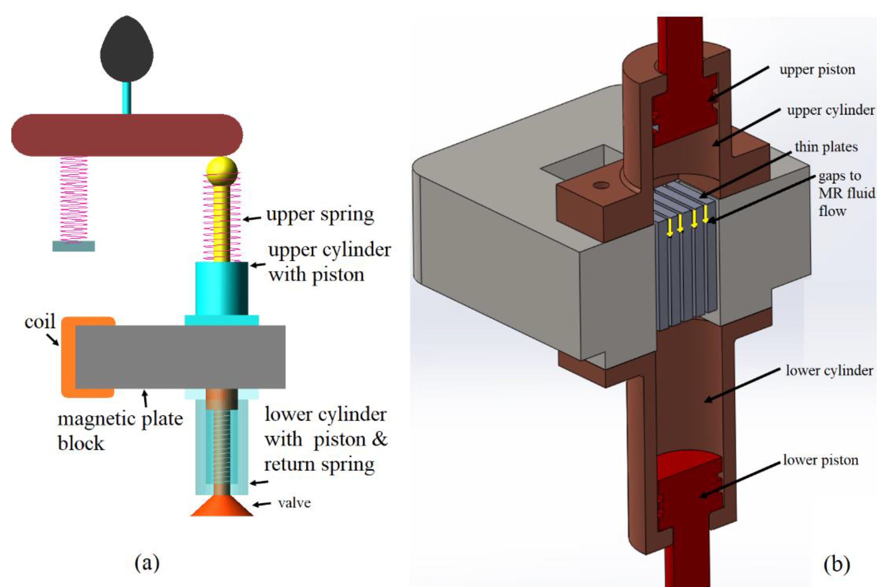
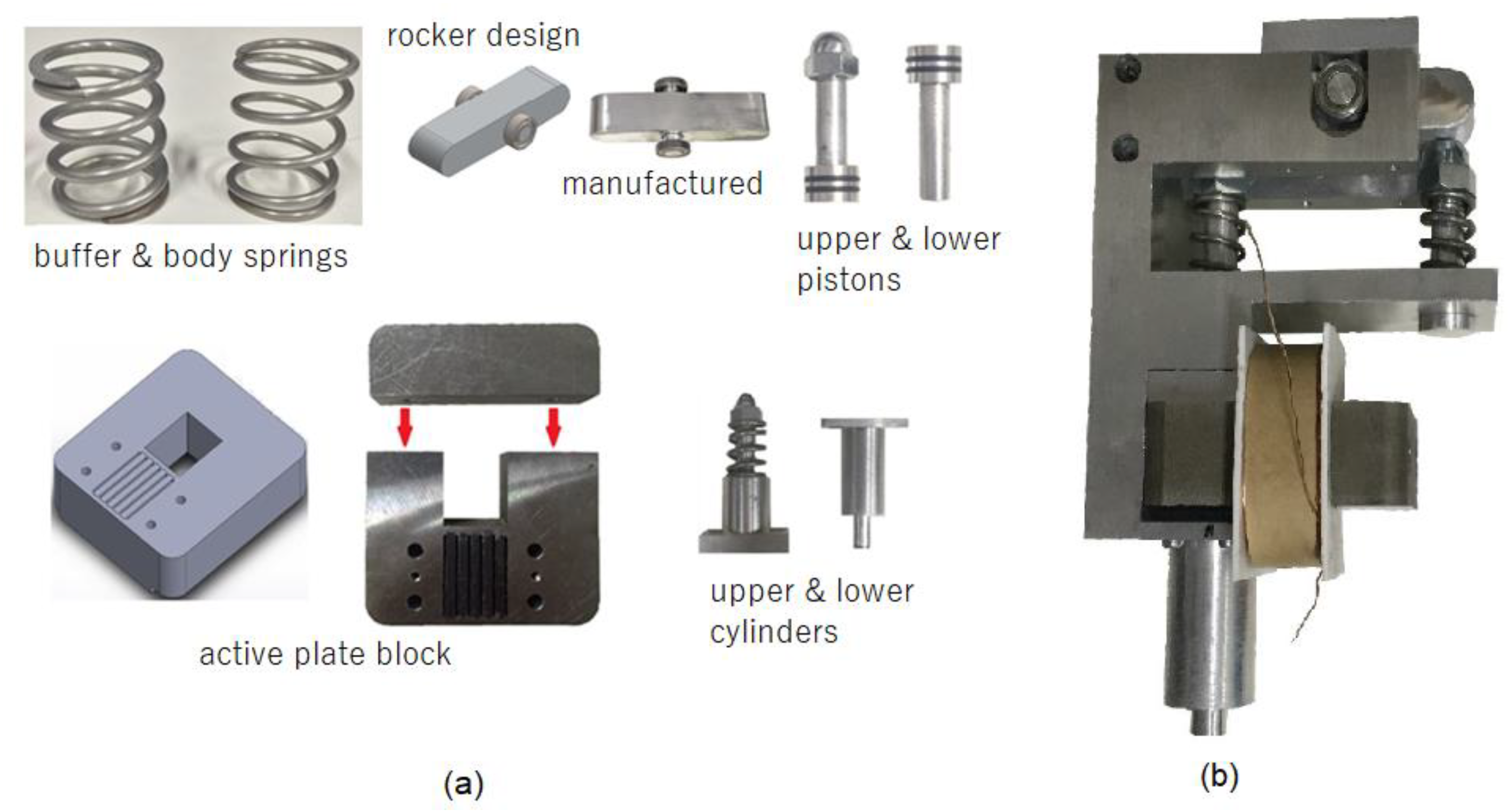
The proposed MR-fluid-based variable valve comprises the following: a rocker arm; an upper piston; a lower piston; a magnetic plate block; three springs, namely a buffer spring, an upper spring, and a return spring, as depicted in Figure 1a. The upper piston is placed in the upper cylinder and connected to the rocker arm through the upper spring. The lower piston is positioned in the lower cylinder and connected to the valve and the return spring. These upper and lower cylinders are filled with MR fluid, and a magnetic plate block separates them. Figure 1b illustrates the arrangement of these cylinders and pistons. The magnetic plate block comprises an electromagnetic coil area, which generates the required magnetic field; a rectangular channel, which transfers the field, and several thin and parallel plates, which facilitate the flow of MR fluid from the upper cylinder to the lower cylinder through the gaps between the aforementioned thin parallel plates.
When the cam rotates with default engine timing, the rocker arm follows the cam, and it transfers equal lift forces to the upper and buffer springs. Then, the upper piston pushes the MR fluid into the cylinder. Thereafter, the MR fluid transfers this pushing force to the lower piston by flowing through the magnetic plate block. The magnetized thin plates in the magnetic plate block resist the MR fluid flow that eventually acts against the lift force distribution from the rocker side to the valve side. The magnitude of this force is proportional to the current in the coil. Therefore, the valve opening timing and lift can no longer follow the default cam timing; they change with the coil current. The working mechanism of the proposed valve train can be explained by dividing the mechanism into three modes: the fully lifted, fully closed, and partially open modes.
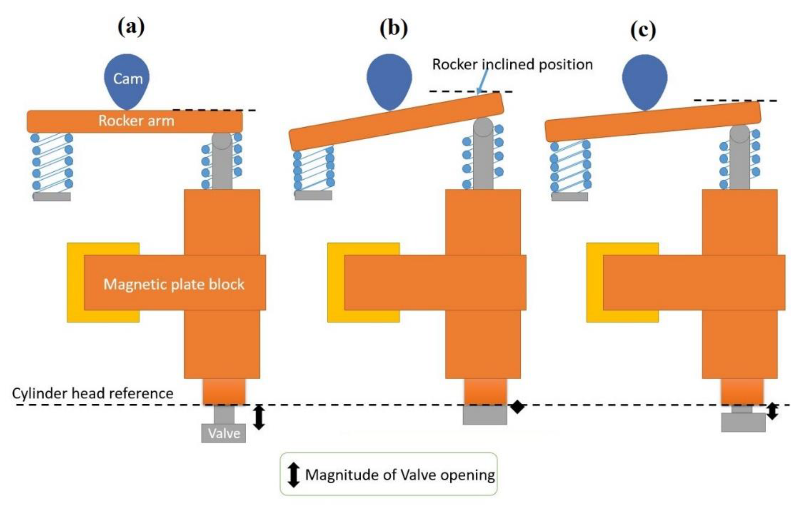
First, Figure 2a shows the MR valve in the fully lifted mode. The cam force is transferred to the rocker arm, then to the body’s upper piston, and finally to the magnetic plate block. At this juncture, the magnetic pole coil does not generate any current, that is, the MR fluid layers do not offer any resistance. Therefore, the valve opens smoothly and completely. During this process, the upper and lower springs, as well as the side-by-side spring, are compressed simultaneously, and the rocker arm moves downward to the horizontal position.
The second mode is the fully closed mode. The positions of the components in this mode are illustrated in Figure 2b. The supply current to the coil is at its maximum, and this increases the resistance force in the MR fluid layers to its maximum level. This resistance force stops the distribution of the lift force, and all the lift force from the rocker is transferred to the buffer spring, meaning that the valve lift is zero.
Finally, in the partially open mode, the valve lift can be controlled by varying the magnitude of the supply current. The supply current generates a magnetic field, which changes the resistance of the MR fluid in the plate block. At this point, the degree to which the valve is open is proportional to the magnitude of the resistance force in the MR fluid. Figure 2c illustrates the partially lifted mode.
In this manner, VVL can be realized. Moreover, by varying the time at which the current is applied, the valve opening time can be varied. However, this device cannot be used to vary the timing of the valve closing. The MR fluid used in this device is MRF-140CG (Lord Corporation, Cary, NC, USA), which is a well-known high-grade MR fluid. Its operating temperature is −40 to 130 °C, its liquid viscosity at 40 °C is 0.280 Pa·s, density is 3.74 g/cm3, and its flashpoint is higher than 150 °C [19]. MRF-140CG offers high resistance against particle sedimentation, meaning that it produces less sediment during short-time idle situations compared with other MR fluids. Moreover, any sedimented iron particles can be easily dispersed within a few running cycles.

3. Magnetic and Thermal Studies

The heart of this new valve is the magnetic plate block, and within this block, the required resistance force of the MR fluid depends on the current flowing through the magnetic coil. Owing to the electrical resistivity of the magnetic coil, some energy is dissipated as heat. This dissipated heat increases the device’s temperature, which, in turn, affects the resistance of the coil and properties of the MR fluid. Therefore, an electromagnetic analysis and heat transfer analysis is needed to understand the performance of the proposed MR valve, and these two aspects of physics must be interlinked. For this reason, the magnetic plate block was analyzed and optimized in this study by performing a coupled magnetic and thermal multiphysics analysis. An early physics concept that relates electrical and thermal fields through a simple equation is the Joule-heating effect [20]:
Q e = I 2 R t .
This equation could be used to determine the Q e , i.e., the amount of heat generated by a coil, where I is the electrical current, R is resistance in the coil, and t is time. Then, the energy balance equation could be used to determine the temperatures in the system (Equation (2)) [21].
ρ C p   Δ T = · k Δ T + Q e .
where ρ , C p ,   and k are the mass density, specific heat, and thermal conductivity of the medium respectively, and Δ T is the temperature gradient. The concept of linear resistivity in metals could be used to obtain the relationship between the temperature and resistance of the coil. According to this concept, the resistivity of the conductor ( σ ) depends on the surrounding temperature as expressed in Equation (3) [21].
σ = σ 0 ( 1 + α T T r e f ,
where   T r e f is the reference temperature, σ 0 is the reference resistivity, and α is the resistivity temperature coefficient. By using the three presented equations, the aforementioned two-way coupled analysis could be performed.
COMSOL Multiphysics GUI software was used to perform the two-way coupled magnetic field and thermal analysis. A three-dimensional model of the magnetic plate block was built, governing equations were incorporated, and simulations were conducted. The magnetic field simulation results were used to determine the shear stress in the MR fluid by using an empirical equation (Equation (4)).
τ y = 0.98 ( B ) 1.61 ,
where τy is the yield stress of the MR fluid under the action of a magnetic field and B is the magnetic flux density. Finally, the resistance force of the MR block ( F T ) was calculated using Equation (5).
F T = n + 1 F a + F d ,
where n is the number of thin plates in MR block around which MR fluid flows, the MR fluid chaining force F a is expressed as in Equation (6), and the viscous damping force ( F d ) is expressed as in Equation (7).
F a = x ˙ x ˙ c 1 τ y L h A p ,
F d = 1 + w h 2 A p 12 μ L A p 2 w h 3 x ˙ = k 12 μ L A p 2 w h 3 x ˙ ,
where the design factors L and w denote the height and width of the magnetic core, respectively; h is the thickness of the MR fluid layer; A p is the effective area of the upper piston; x ˙ is the liquid flow rate. The value of the parameter c 1 ranged between 2.07 and 3.07, and it was determined using Equation (8).
c 1 = 2.07 + 12 Q μ 12 Q μ + 0.4 w h 2 τ y ,
In Equation (8), μ denotes the viscosity coefficient of the MR fluid, and k was computed using Equation (9).
k = 1 + w h / 2 A p .
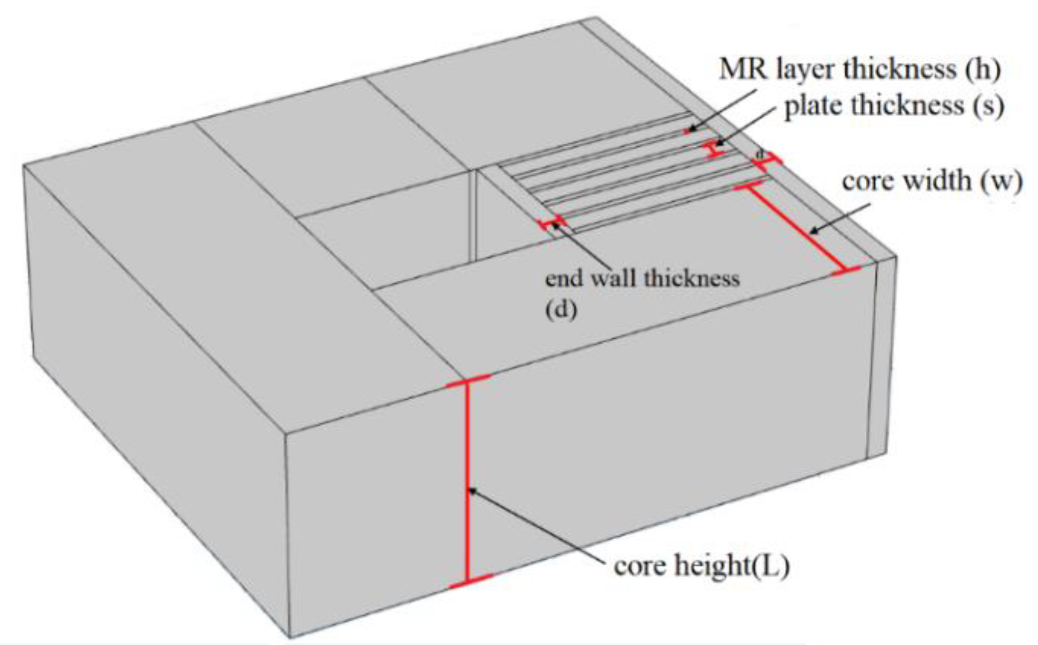
According to Equation (6), the required resistance force depends on the magnetic field and design factors. Because of the restrictions on the engine’s volume and the temperature limit of the MR fluid, the maximum possible resistance force had to be achieved with the smallest possible device size and lowest possible temperature. The input current, magnetic core channel material, and design factors such as the magnetic core area (A = w L), MR fluid layer thickness (h), partition plate thickness (s), and end wall thickness (d) were the major factors considered for minimizing the device size and temperature without compromising its resistance force. These dimensions were optimized by performing simulations. Owing to design limitations, standard optimization techniques could not be employed. Therefore, the following local optimization procedure was used. To determine the maximum possible temperature, steady-state analysis was performed in this multiphysics simulation.
First, the thicknesses of the MR layer and the partition plate were optimized. The resistance offered by the MR fluid layer is inversely proportional to its thickness. However, if the MR fluid layer is too thin, the MR fluid cannot pass, and the plates come into direct contact with each other. This creates excessive resistance, thereby preventing plate movement. Therefore, the thickness of the MR fluid layer was set to 1 mm. Similarly, the resistance force is inversely proportional to the separator thickness. However, the separator plates should have a certain minimum thickness to prevent their deformation. Therefore, the separator plate thickness was set to 3 mm. To increase the resistance offered by the valve, a large number of layers are needed. However, the cylinder head limits the available space for the number of layers, and it depends on the thickness of the MR layer and the partition plate. Finally, in the existing limited volume, six MR layers and five partition plates with the best possible thicknesses were used in the proposed design, as illustrated in Figure 3.
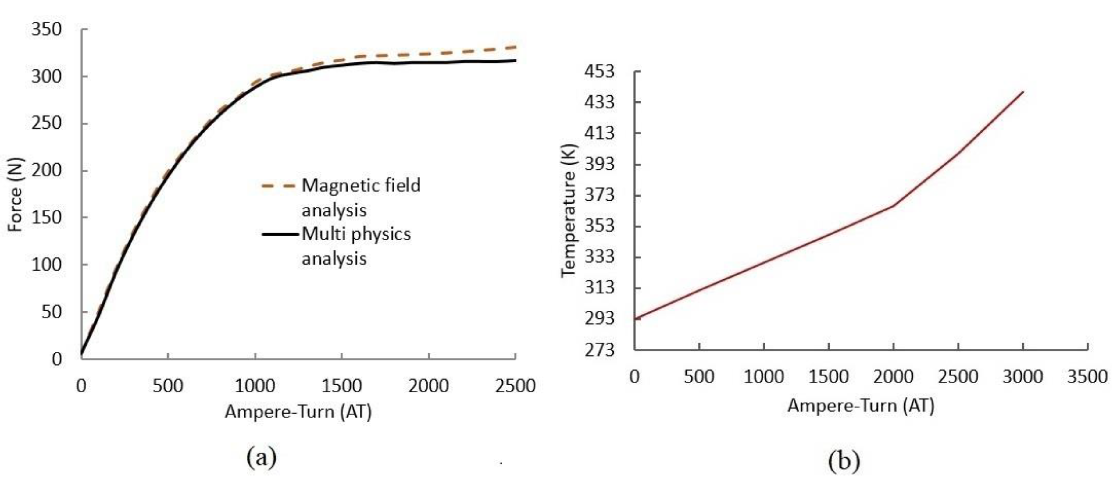
Second, the maximum possible input current was estimated. Magnetic materials reach saturation at the maximum possible input supply. This affects the magnetic field and, eventually, the resistance force. The input supply is the product of the applied current and number of turns. For the selected coil wire, the maximum supply was 2 A. Therefore, it was important to identify the number of coil turns (T) that would achieve the maximum torque. 
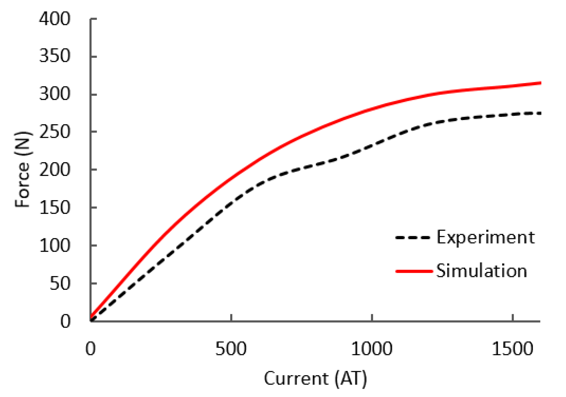
Figure 4 shows the resistance force and MR layer temperature corresponding to different numbers of ampere-turns (ATs). The multiphysics simulation results were more accurate than those of the conventional magnetic field simulations because the multiphysics simulation considered the effects of working temperature on coil resistivity. Especially at higher input ATs, the multiphysics simulation yielded more accurate results, as depicted in Figure 4a. The maximum force was reached when the magnetic flux channel was magnetically saturated. For this reason, after 1500 AT, the resistance force did not increase.
Moreover, the slope of the temperature rise in Figure 4b increases after 2000 AT. This is because the heat generated by the coil was considerably higher than the heat transferred to the surrounding. Therefore, 1500 AT—750 coil turns—is appropriate for this device.
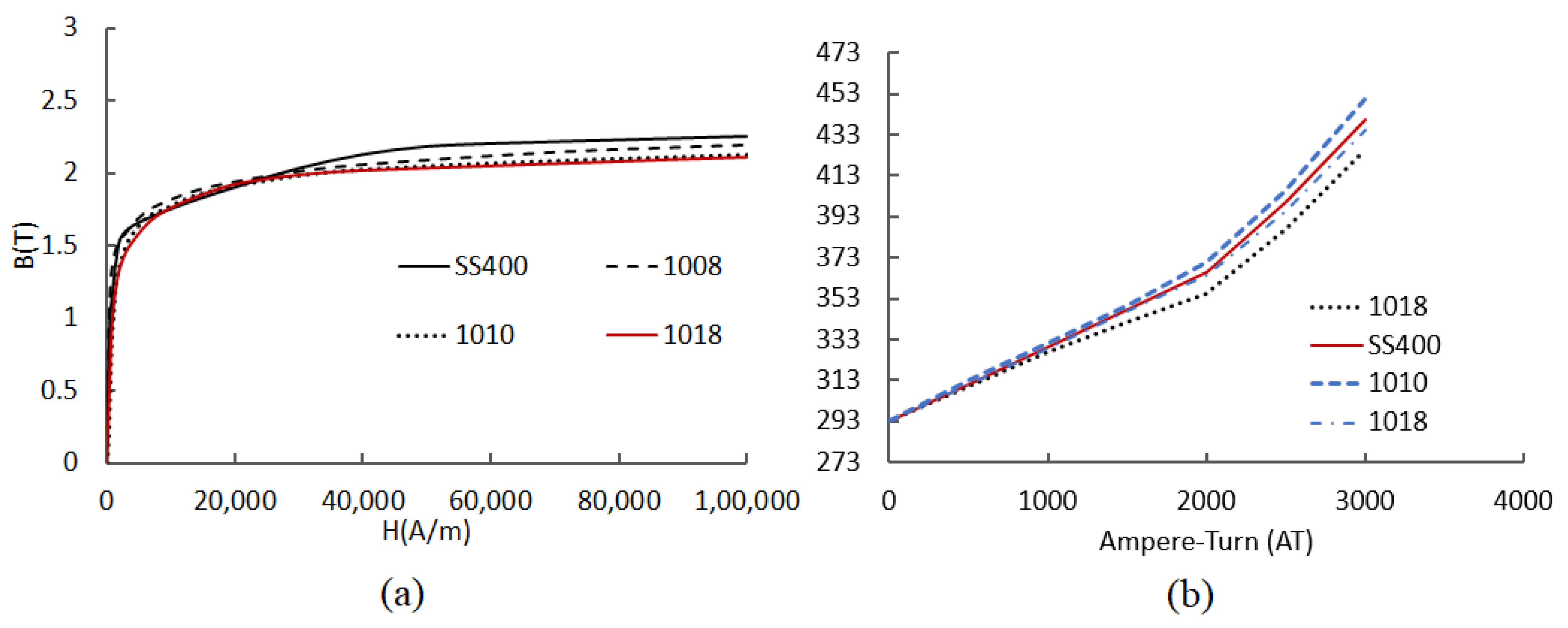
Third, the magnetic core channel material was selected. It was decided that this material must have high magnetic permeability and favorable thermal conductivity. In this study, steel alloys, including AISI1010 containing 0.1% carbon, AISI 1008 containing 0.08% carbon, and AISI 1018 containing 0.18% carbon, as well as SS400 containing 0.15–0.2% carbon, were used. By considering the magnetic permeability properties depicted in Figure 5a, temperature conditions depicted in Figure 5b, and suggestions from various manufacturers, SS400 was finally selected as the study material.
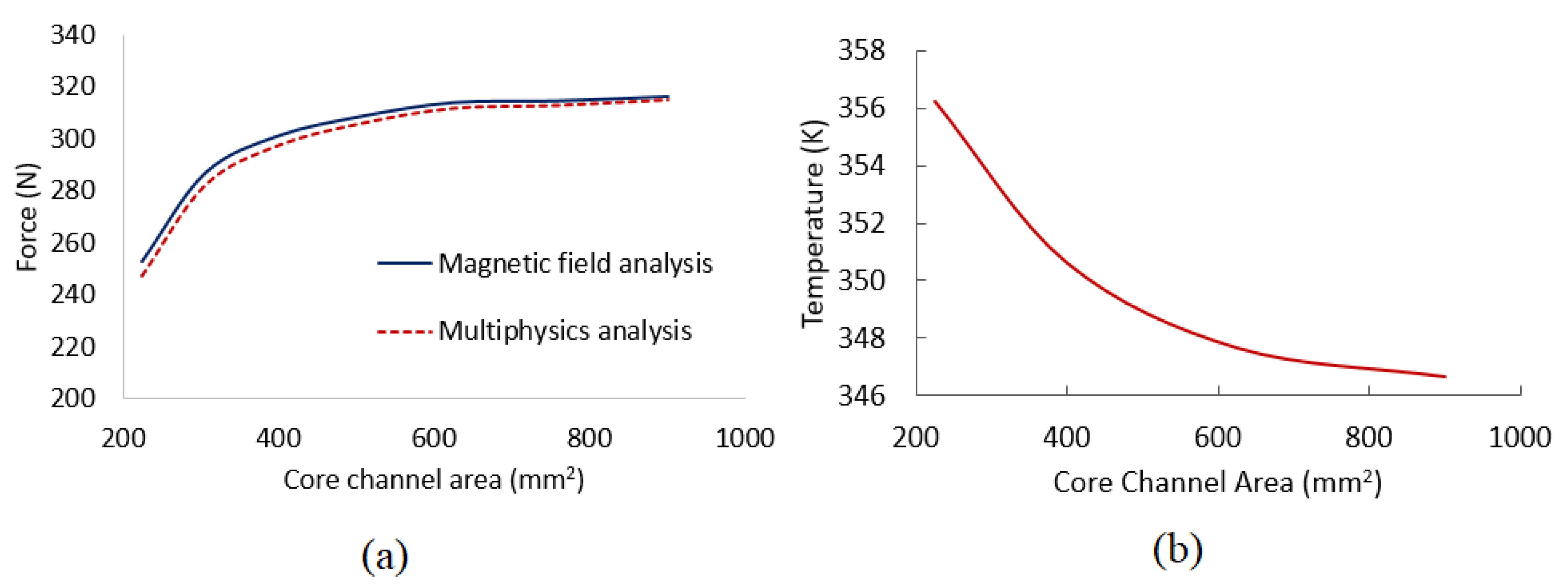
Then, the optimal magnetic core area (A) was estimated. This area must be less than the available space for the valve train in the engine, that is, 900 mm2. Figure 6 shows an analysis of the effects of the channel area on the output force and temperature of the device. According to Figure 6a, the smaller the area, the lower the resistance force. However, for areas exceeding 625 mm2, this relationship was found to be weak; for example, the force generated with the channel area of 625 mm2 was 99.28% of the force with the channel area of 900 mm2. By contrast, as illustrated in Figure 6b the temperature of the MR fluid was lower when the area was larger, which facilitated more heat transfer. However, this drop was not considerable for areas larger than 700 mm2. Therefore, 625 mm2 was set as the optimal dimension of the proposed device. By performing simple magnetic simulations and multiphysics simulations, the output force could be estimated. As depicted in Figure 6a, the difference between these two types of simulation results was not substantial. However, this difference was marginally larger when the channel area was smaller, owing to the high temperature of the MR fluid.
Finally, to overcome the fluid leakage problem, the end wall was designed to block the MR fluid on both sides of the MR layer plates. Moreover, this wall improved heat transfer and reduced the temperature of the MR layer. As illustrated in Figure 7b, as the end wall’s thickness increased, the MR fluid temperature decreased. However, as the end wall’s thickness was increased, the resistance force decreased, as illustrated in Figure 7a. This was because the flux bypassed through this end wall. The difference in magnitude of the force for wall thicknesses of 3 and 1 mm was only 10 N. However, when the wall thickness was increased further, the resistance force decreased considerably. Therefore, 3 mm was considered to be the optimal thickness of the end wall. Both simple magnetic simulation and multiphysics simulations were performed to estimate the output force. As illustrated in Figure 7a, when the end wall’s thickness was smaller, the values yielded by the multiphysics simulations were lower than those yielded by the normal magnetic field simulation. This was because of the high temperature in the device.
The device dimensions were optimized on the basis of the results of the multiphysics analysis; the final values are summarized in Table 1. 
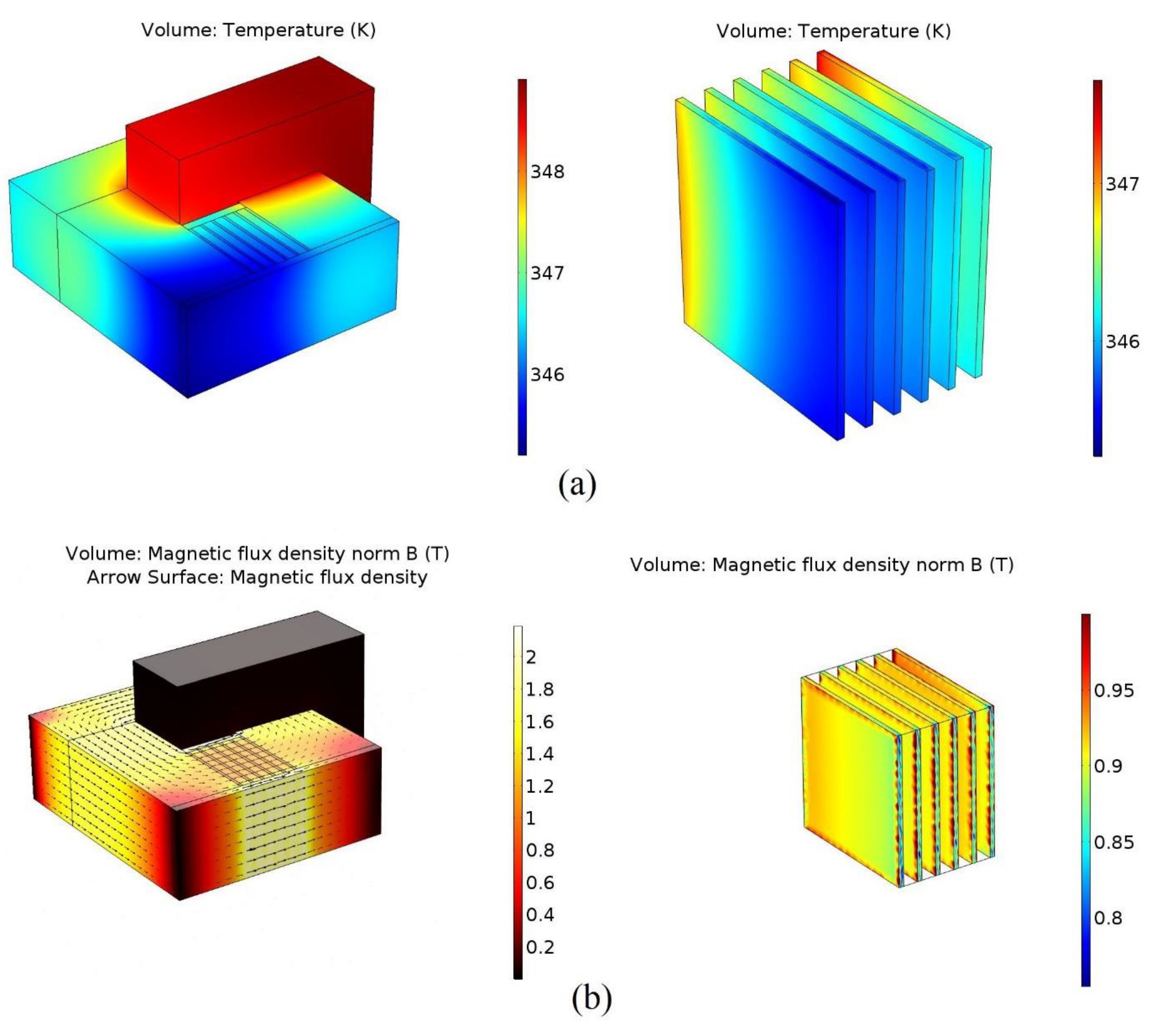
Figure 8 depicts the temperature distribution and magnetic flux density in the channel and MR layers. Even though one end of the valve was inserted in the combustion chamber, the temperature in the other end, i.e., the MR valve train side, was around 40 °C only. This is because of the engine cooling system and cool intake [22]. With an initial temperature of 40 °C, a steady-state analysis was conducted to understand the maximum possible temperatures of the MR layers. The results indicated a rise of 35 °C and that the maximum temperature of the MR layers was 70 °C. However, this temperature did not exceed the operating limits of the MR fluid.

4. Experimental Study

After the multiphysics analysis, a valve train model was designed and dynamic simulations were conducted in the Adams software environment to understand the dynamic conditions. The maximum resistance force (300 N) in the magnetic plate block, as derived from the magnetic simulations, was used as the input for the model. The corresponding elastic coefficients of the springs were calculated and applied to the model. Figure 1a shows the simulation model of the proposed MR valve. Detailed explanations of the MR valve models and dynamic simulations can be found in the literature [15]. This paper focuses on the results of the experimental test and compares them with the simulation results. A valve prototype was fabricated for further experimental tests. The springs required for the aforementioned resistance force were selected, and the other components were manufactured by considering the design parameters. The major components are depicted in Figure 9a. All the parts were tested individually for accuracy and matching. The assembled device is illustrated in Figure 9b.

4.1. Test Setup

A servo motor was used to drive the experimental platform that was used to simulate the rotary motion of the engine camshaft. In principle, the magnetization of the MR valve is required only during low engine speeds, i.e., below 1000 rpm. At higher speeds, the full valve opening is needed as per the cam profile, hence magnetization of the MR valve is not required. Therefore, the cam rotation speed for this prototype test setup was 500 rpm (engine crank speed is two times to cam speed). In this experiment, a Sym-Wolf-R-125 camshaft was used, which is illustrated in Figure 10; its dimensions were as follows: total length of 31.4 mm, base circle diameter of 25.3 mm, and full lift of approximately 6.2 mm. Figure 11 shows the experimental platform after the assembly of the proposed valve. The measuring instruments used in this experiment were a displacement sensor (Linear variable differential transformer) to measure lift, an encoder to measure the angle, an FG-5100 pull gauge to measure the impedance, and a National Instruments kit for reading signals.

4.2. Test Procedure

Before the tests begun, an impedance test was conducted to determine the real-time resistance force from the magnetic plate block and compare it with the magnetic simulation results. Then, the currents required for different values of lift were identified. The trend is illustrated in Figure 12. At higher current, the resistance force was higher, and the lift was smaller. When the valve was fully closed, the required current was 0.61 A.
The experimental tests were divided into three steps: VVL, VVT, and variable valve lift and timing. First, in the variable lift experiments, the valve lift was controlled by adjusting the magnitude of the applied current. The experiments were conducted for 100% (approximately 6.1 mm), 85% (approximately 5.27 mm), 70% (approximately 4.34 mm), and 0% (fully closed) lifts to confirm the possibility of VVL. Second, variable timing tests were conducted for different valve opening points by changing the timing of the current supply, as depicted in Figure 13. Generally, the cam activates the valve-opening angle (117°). If a late opening angle is required (i.e., 175°), the full-magnitude current must be supplied until the required opening angle (i.e., 175°) is reached. Then, the current is decreased to zero to ensure that the inlet valve starts to open.
Owing to design restrictions, the valve closing angle could not be varied. Therefore, the valve-closing angle was fixed as the default cam closing angle. Finally, the variable lift and timing experiments were conducted jointly by controlling the magnitude of the applied current and the energization time point. Tests were conducted for 85% valve lift with various valve opening times and 70% valve lift with various valve timings. Then, these results were compared with the results of the dynamic simulations to verify whether the valve could achieve a high degree of freedom in terms of variable timing and lift.

5. Results and Discussion

A comparison of the experimental results with the magnetic simulation results, as depicted in Figure 14, revealed that the resistance force recorded in the experiments was slightly lower than that obtained in the simulations. This may be due to the magnetic permeability channels not being integrally formed, and the magnetic resistance, due to the air gap generated in the middle, being increased. However, when the current supplied was 1500 AT, the resistance force of the resistance valve was 274 N, which is adequate for the purpose of the proposed electronic valve.

5.1. Variable Valve Lift

As shown in Figure 15, the experimental and dynamic simulation results were similar in the maximum-lift mode, and the overall waveforms are identical. The only difference is that the valve lift occurred marginally earlier in the experiments than in the simulations, possibly because the spring used in the experiments was softer than that included in the simulations.
Similarly, the experimental results obtained with the 85% and 70% lift modes were almost equal to those obtained in the simulations, as depicted in Figure 16. However, under the lower-lift condition, the closing side profile of the valve in the experiment had less lift than that in the simulation. Magnetic hysteresis is one of the major issues in electromagnetic devices, which affects the response rate of the devices. This was because of the inertial force and magnetic hysteresis in the magnetic plate block. Figure 17 shows the experimental results obtained in different lift modes. According to these results, it is evident that VVL is possible with this innovative MR valve train.

5.2. Variable Valve Timing

VVT is an important control scheme that increases the combustion efficiency of an engine at various speeds, thereby reducing air pollution and fuel consumption. Because of design restrictions, with the proposed valve, only the angle at which the valve opens can be controlled; the valve closing time cannot be controlled. Therefore, the valve closing time was fixed by considering the cam profile. Figure 18 shows the experimental results for opening angles of 145°, 175°, and 200°.
The experimental results indicated that variable timing could be achieved with favorable control when the opening angle was small. For instance, as shown in Figure 18a, at 145°, the amount of lift was almost 6 mm, similar to the simulation result. This is good for early valve-opening timing control. However, for valve angles of 175° (late valve-opening timing) and higher, the experimental results indicated that the lifts were 1 mm smaller than those recorded in the simulations, possibly because of the hysteresis characteristics of the MR fluid. Moreover, spring strength, mechanical inertia, and friction cause a lag in the maximum lift. Nonetheless, with the proposed device, the aim was to achieve variable valve profiles; the accuracy of these profiles was not a focus. Figure 19 depicts the different valve timing profiles achieved using the MR valve during the experiments. Even though the accuracy of these profiles was not as expected, the timing flexibility of the MR valve was found to be reliable nonetheless.

5.3. Variable Valve Timing and Lift

The final experiment conducted in this study was on variable timing and lift. Various timings and lifts were added in combination. The experiments were conducted with valve opening timings at angles of 145°, 175°, and 200°, with valve lifts of 85% and 70%. The maximum current was applied until the valve-opening angle was reached; then, the magnitude of the applied current was reduced to achieve the required lift percentage. Figure 20 shows the results of the experiments conducted with 85% lift and various timings. The control was good in the timing part, and the 85% lift was achieved accurately.
Figure 21 shows the experimental results with the same varied timing for the valve opening angles of 145°, 175°, and 200° as well as the lift adjustment of 70%. The required VVT was also achieved efficiently for this lift, and the control was rather good. The designed lift was reached.
However, for late valve opening, the valve profiles did not coincide with their possible maximum points. As explained, this was caused by magnetic hysteresis. However, this valve train was established to achieve variable profiles, not to achieve a standard profile. By controlling the magnitude of the input current, the shape of the profile can be controlled. All the presented results revealed that the proposed valve train can deliver the desired valve profiles, namely VVT, VVL, VVT and VVL. Consequently, the proposed MR valve train is valid and valuable.
Moreover, the response time of this valve train is 90 ms (~11 Hz), which means the demagnetization problem is a major issue after 660 rpm. However, this problem can be overcome by using hybrid (positive and negative) current input instead of DC supply. Therefore, further research is needed on the hysteresis effect on MR valve performance and control input signal to achieve the best performance.

6. Conclusions

In this study, multiphysics analyses and experimental validations were performed on a new MR valve that provides flexibility in terms of valve opening timing and the magnitude of the valve lift. Because the MR device is governed by multiple physics theories, a finite-element-based multiphysics analysis was performed for the magnetic plate block optimization. In this multiphysics study, magnetic field and heat transfer analyses were performed jointly to understand the magnetic flux density and temperature rise in the MR fluid layers. The results indicated that the flux density required to generate the resistance force of 300 N was achieved in the MR fluid, and the operating temperature of the MR fluid was 70 °C, which is within the prescribed temperature limits. To understand the working of the proposed device in real time, a prototype was manufactured and tested on a test bench. The variable valve lift profiles from the test results were almost the same as the results of the computer simulations. Therefore, the proposed flexible MR valve train can be used in engines to achieve VVT and VVL.

Author Contributions

Conceptualization, Y.S. and M.B.K.; methodology, Y.S. and M.B.K.; software, M.B.K.; validation, M.B.K.; formal analysis, M.B.K.; investigation, M.B.K.; resources, Y.S.; data curation, Y.S.; writing—original draft preparation, M.B.K.; writing—review and editing, Y.S.; supervision, Y.S.; project administration, Y.S.; funding acquisition, Y.S. All authors have read and agreed to the published version of the manuscript.

Funding

This research is financially supported by Ministry of Science and Technology, Taiwan (project number: MOST 105-2221-E-027-091).

Conflicts of Interest

The authors declare no conflict of interest.

References

  1. Yao, G.Z.; Yap, F.F.; Chen, G.; Li, W.; Yeo, S.H. MR damper and its application for semi-active control of vehicle suspension system. Mechatronics 2002, 12, 963–973. [Google Scholar] [CrossRef]
  2. Chen, B.; Sun, Y.Z.; Li, Y.L.; Zhao, S.L. Control of seismic response of a building frame by using hybrid system with magnetorheological dampers and isolators. Adv. Struct. Eng. 2014, 17, 1199–1215. [Google Scholar] [CrossRef]
  3. Nguyen, Q.H.; Lang, V.T.; Choi, S.B. Optimal design and selection of magnetorheological brake types based on braking torque and mass. Smart Mater. Struct. 2015, 24, 067001. [Google Scholar] [CrossRef]
  4. Shiao, Y.; Nguyen, Q.A. Development of a multipole magnetorheological brake. Smart Mater. Struct. 2013, 22, 065008. [Google Scholar] [CrossRef]
  5. Shiao, Y.; Hoang, T.; Kantipudi, M.B.; Kao, N.-C.; Lai, C.-H. Development of a Multilayered Magnetorheological Brake for Knee Orthosis Applications. J. CSME 2021, 42, 81–91. [Google Scholar]
  6. Sun, S.S.; Ning, D.H.; Yang, J.; Du, H.; Zhang, S.W.; Li, W.H. A seat suspension with a rotary magnetorheological damper for heavy-duty vehicles. Smart Mater. Struct. 2016, 25, 105032. [Google Scholar] [CrossRef]
  7. Sarkar, C.; Hirani, H.; Sasane, A. Magnetorheological smart automotive engine mount. Int. J. Curr. Eng. Technol. 2015, 5, 419–428. [Google Scholar]
  8. Yoo, J.H.; Wereley, N.M. Design of a high-efficiency magnetorheological valve. J. Intell. Mater. Syst. Struct. 2002, 13, 679–685. [Google Scholar] [CrossRef]
  9. Ichwan, B.; Mazlan, S.A.; Imaduddin, F.; Koga, T.; Idris, M.H. Development of a modular MR valve using meandering flow path structure. Smart Mater. Struct. 2016, 25, 037001. [Google Scholar] [CrossRef]
  10. Cleary, D.; Silvas, G. Unthrottled Engine Operation with Variable Intake Valve Lift, Duration, and Timing; SAE Technical Paper No. 2007-01-1282; SAE International: Warrendale, PA, USA, 2007. [Google Scholar]
  11. Dat, L.V.; Shiao, Y. Design of a New Electromagnetic Valve with a Hybrid Pm/Em Actuator in Si Engines. J. Mar. Sci. Technol. 2014, 22, 687–693. [Google Scholar]
  12. Hosaka, T.; Hamazaki, M. Development of the Variable Valve Timing and Lift (VTEC) Engine for the Honda NSX; SAE Technical Paper No. 910008; SAE International: Warrendale, PA, USA, 1991. [Google Scholar]
  13. Bernard, L.; Ferrari, A.; Micelli, D.; Perotto, A.; Rinolfi, R.; Vattaneo, F. Electro-hydraulic valve control with multiair technology. MTZ Worldw. 2009, 70, 4–10. [Google Scholar] [CrossRef]
  14. Shiao, Y.; Kantipudi, M.B.; Yang, T.H. Performance estimation of an engine with magnetorheological variable valve train. Adv. Mech. Eng. 2019, 11, 1687814019847795. [Google Scholar] [CrossRef]
  15. Shiao, Y.; Kantipudi, M.B.; Jiang, J.W. Novel Spring-buffered Variable Valve Train for an Engine using Magnetorheological Fluid Technology. Front. Mater. 2019, 6, 95. [Google Scholar] [CrossRef] [Green Version]
  16. Shiao, Y.; Gadde, P.; Kantipudi, M.B. Mode Strategy for Engine Efficiency Enhancement by Using a Magneto-Rheological Variable Valve Train. J. Energy Resour. Technol. 2021, 143, 062307. [Google Scholar] [CrossRef]
  17. Patil, S.R.; Powar, K.P.; Sawant, S.M. Thermal analysis of magnetorheological brake for automotive application. Appl. Therm. Eng. 2016, 98, 238–245. [Google Scholar] [CrossRef]
  18. Wang, Y.; Li, S.; Meng, W. Strong coupling analysis of fluid–solid for magnetorheological fluid braking system. J. Intell. Mater. Syst. Struct. 2018, 29, 1586–1599. [Google Scholar] [CrossRef]
  19. Lord-Corporation. Magneto-Rheological Fluid MRF-140CG. 2012. Available online: https://lordfulfillment.com/pdf/44/DS7012_MRF-140CGMRFluid.pdf (accessed on 28 May 2021).
  20. Balmer, R.T. Modern Engineering Thermodynamics—Textbook with Tables Booklet; Academic Press: Cambridge, MA, USA, 2011. [Google Scholar]
  21. Dellinger, J.H. The temperature coefficient of resistance of copper. J. Frankl. Inst. 1910, 170, 213–216. [Google Scholar] [CrossRef]
  22. Cerdoun, M.; Khalfallah, S.; Beniaiche, A.; Carcasci, C. Investigations on the heat transfer within intake and exhaust valves at various engine speeds. Int. J. Heat Mass Transf. 2020, 147, 119005. [Google Scholar] [CrossRef]
Figure 1. New magnetorheological (MR) valve train: (a) block diagram and (b) sectional view of the cylinders and plate block.
Applsci 12 09109 g001
Figure 2. Working modes: (a) fully lifted, (b) fully closed, and (c) partially open.
Applsci 12 09109 g002
Figure 3. Design factors of magnetic plate block.
Applsci 12 09109 g003
Figure 4. Effects of the input current on the (a) resistance force and (b) MR fluid temperature.
Applsci 12 09109 g004
Figure 5. Effects of the core material on the (a) B–H curve and (b) MR fluid temperature.
Applsci 12 09109 g005
Figure 6. Effects of the core area on the (a) resistance force and (b) MR fluid temperature.
Applsci 12 09109 g006
Figure 7. Effects of the end wall’s thickness on the (a) resistance force and (b) MR fluid temperature.
Applsci 12 09109 g007
Figure 8. Three-dimensional model simulation results: (a) temperature of the magnetic plate block and MR layers and (b) magnetic flux density in the channel and MR layers.
Applsci 12 09109 g008
Figure 9. MR valve train: (a) manufactured parts and (b) assembly.
Applsci 12 09109 g009
Figure 10. Camshaft with a default cam profile.
Applsci 12 09109 g010
Figure 11. Experimental setup for testing the proposed MR valve train.
Applsci 12 09109 g011
Figure 12. Required current for various valve lifts.
Applsci 12 09109 g012
Figure 13. Timing of current supply for different valve timings.
Applsci 12 09109 g013
Figure 14. Resistance force values obtained in the experiments and simulations.
Applsci 12 09109 g014
Figure 15. Full opening test results of the valve.
Applsci 12 09109 g015
Figure 16. Test results obtained for (a) 85% and (b) 70% valve opening.
Applsci 12 09109 g016
Figure 17. Experimental results with variable valve lift.
Applsci 12 09109 g017
Figure 18. Comparison of variable timing results for opening angles of (a) 145°, (b) 175°, and (c) 200°.
Applsci 12 09109 g018
Figure 19. Variable valve timing test results at 100% lift.
Applsci 12 09109 g019
Figure 20. Variable timing and lift test results (85% lift).
Applsci 12 09109 g020
Figure 21. Variable timing and lift test results (70% lift).
Applsci 12 09109 g021
Table 1. Final dimensions of the magnetic plate block.
Design VariableOptimized Dimensions
core materialSS400
magnetic channel area (a)625 mm2
MR layer thickness (h)1 mm
separator plate thickness (s)3 mm
end-wall thickness (d)3 mm
coil turns750
resistance force303.87 N
Publisher’s Note: MDPI stays neutral with regard to jurisdictional claims in published maps and institutional affiliations.

