

Adaptive Control of Flapping-Wing Micro Aerial Vehicle with Coupled Dynamics and Unknown Model Parameters


Abstract
:1. Introduction
2. Design and Modeling
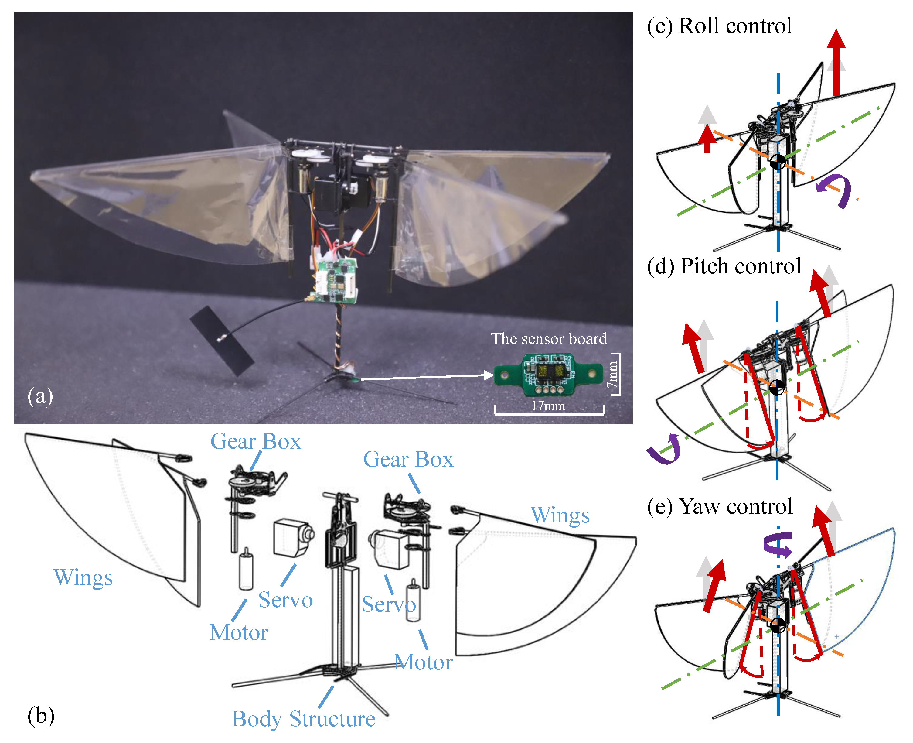
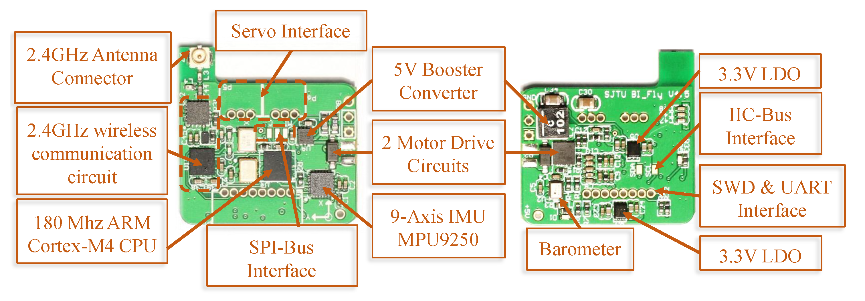
2.1. FMAV Platform
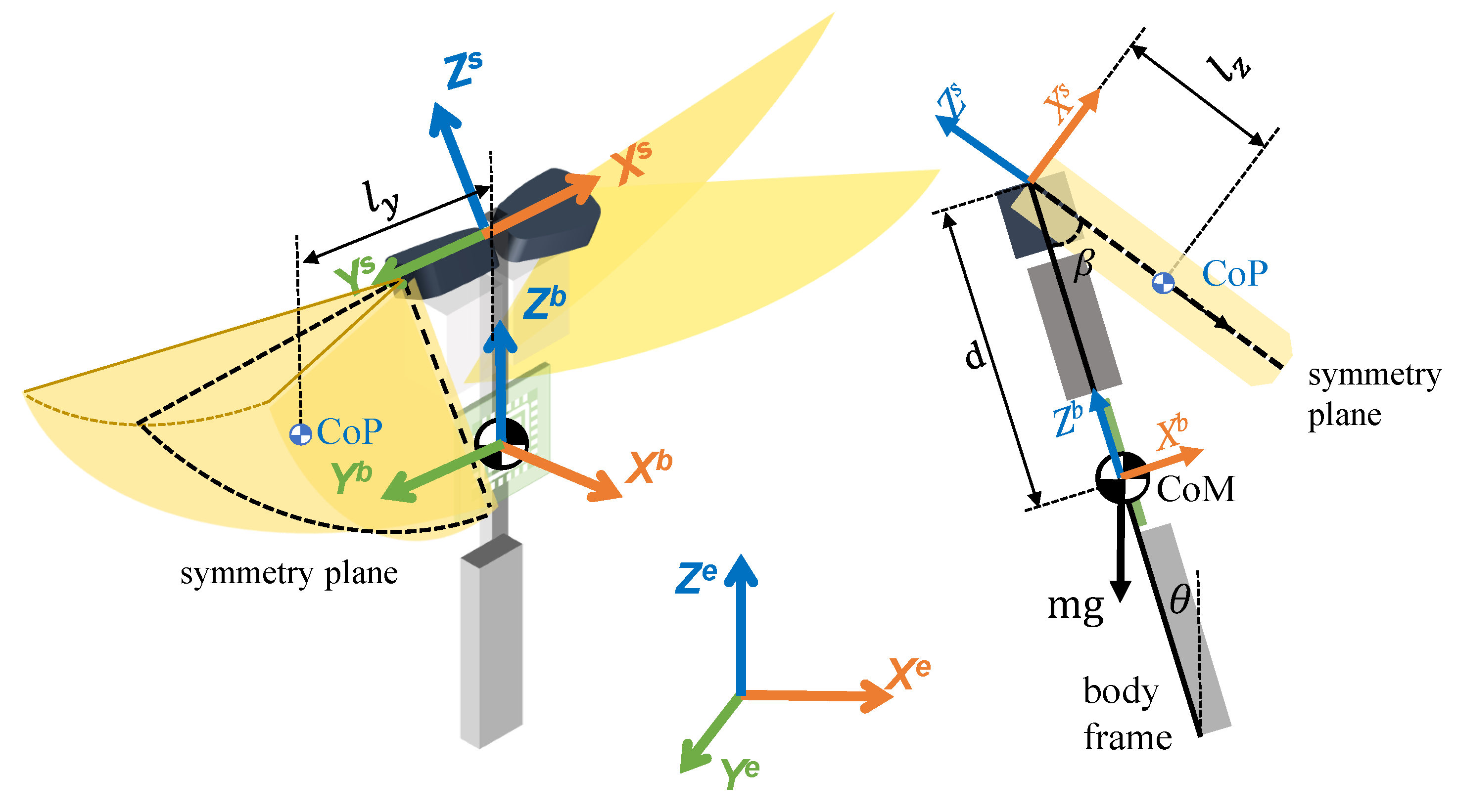
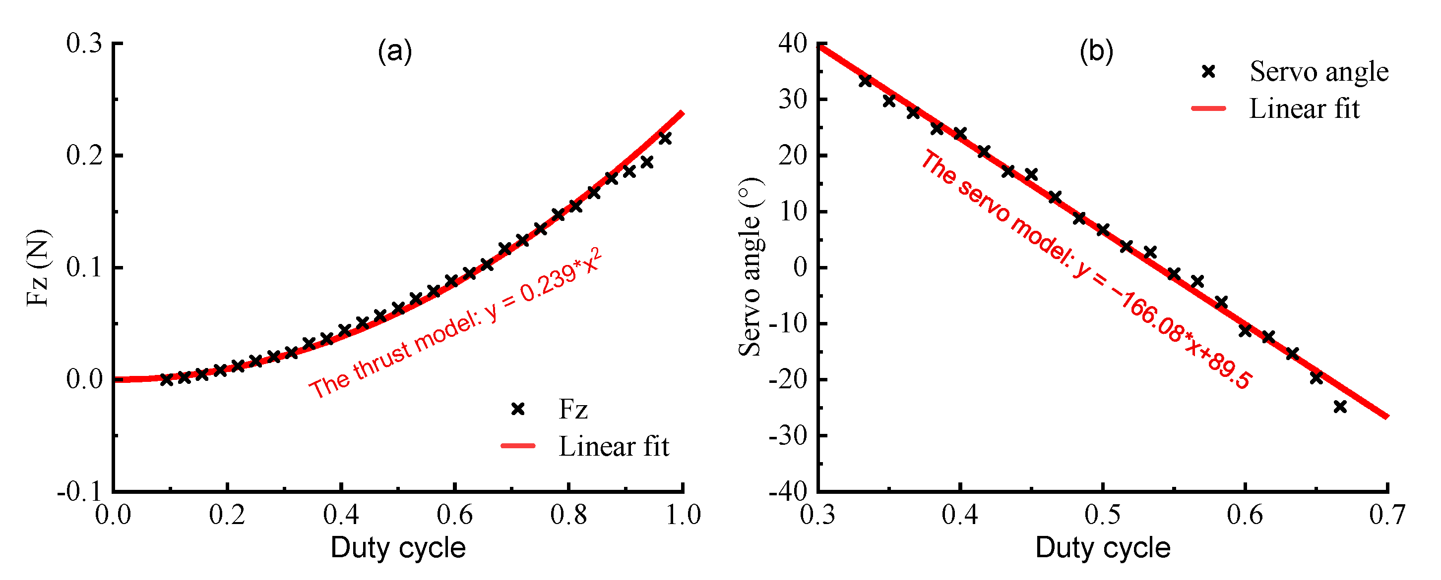
2.2. Modeling and the Control Allocation
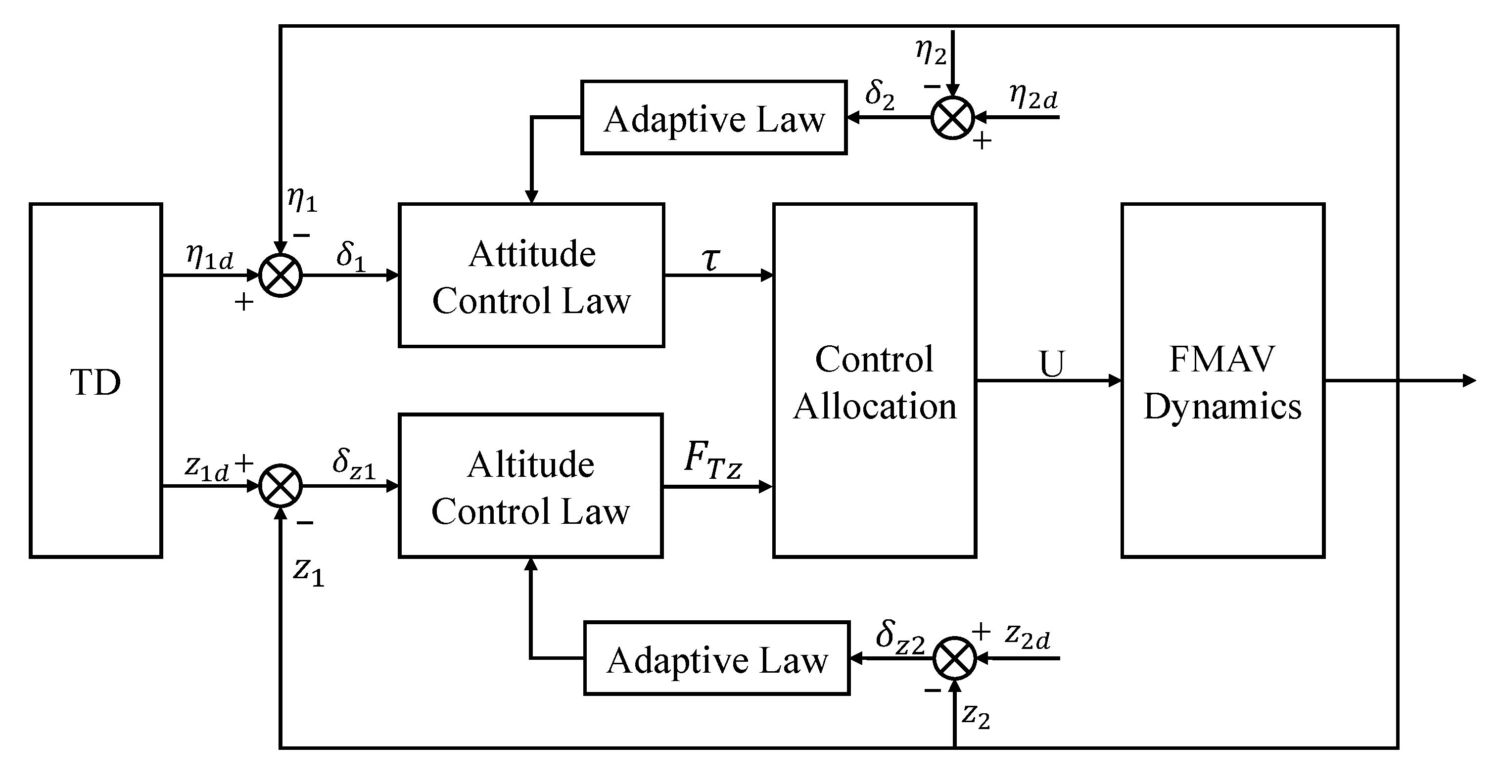
3. Flight Control
3.1. Tracking Differentiator (TD)
3.2. Attitude Controller
3.3. Altitude Controller
4. Experiment and Discussion
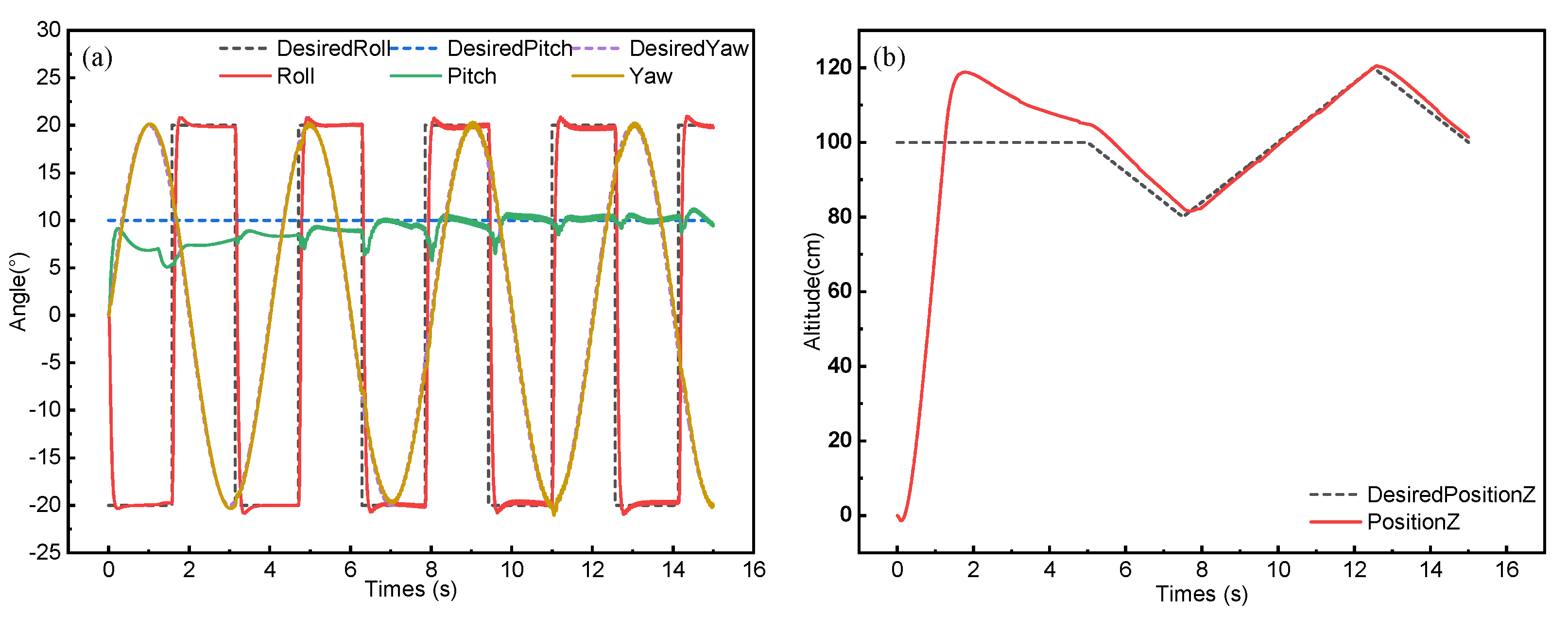
4.1. Simulation
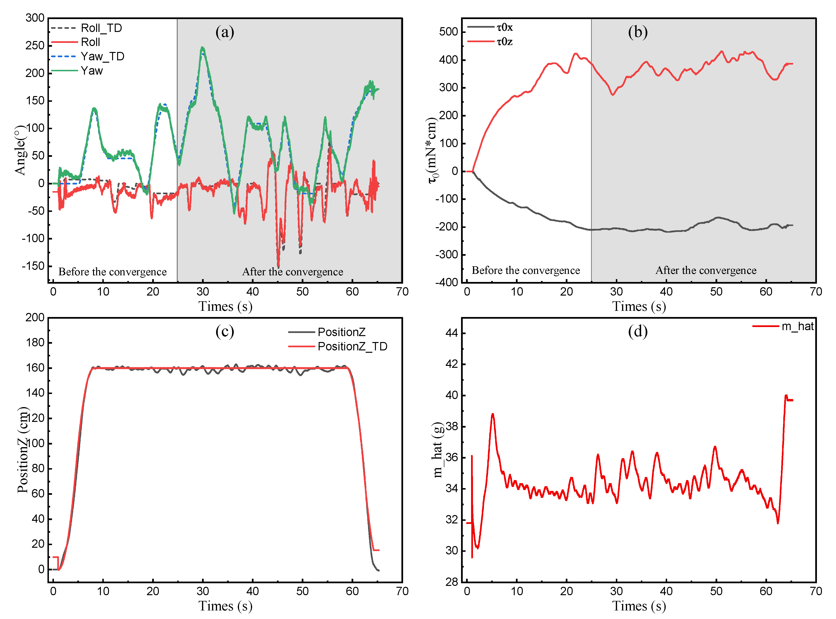
4.2. Flight Test
5. Conclusions
Author Contributions
Funding
Institutional Review Board Statement
Informed Consent Statement
Data Availability Statement
Acknowledgments
Conflicts of Interest
Abbreviations
| FMAV | Flapping-wing Micro Aerial Vehicle |
| DARPA | Defense Advanced Research Projects Agency |
| ADRC | Active Disturbance Rejection Controller |
| TD | Tracking Differential |
| PCB | Printed Circuit Board |
| CoM | Center of Mass |
| CoP | Center of Pressure |
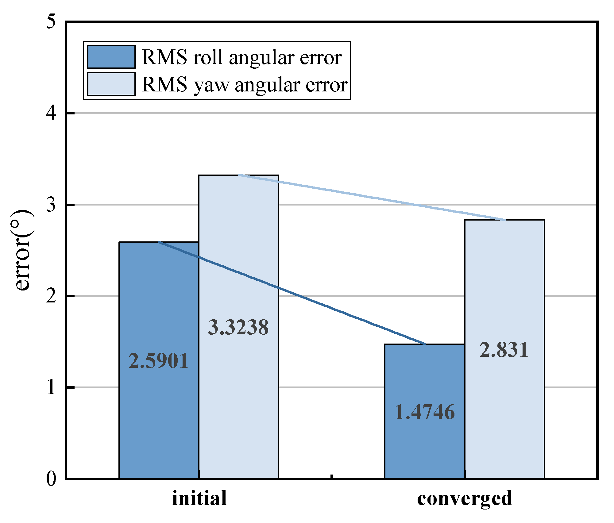
| RMS | Root-Mean-Square |
References
- Ellington, C.P.; Van Den Berg, C.; Willmott, A.P.; Thomas, A.L. Leading-edge vortices in insect flight. Nature 1996, 384, 626–630. [Google Scholar] [CrossRef]
- Dickinson, M.H.; Lehmann, F.O.; Sane, S.P. Wing rotation and the aerodynamic basis of insect flight. Science 1999, 284, 1954–1960. [Google Scholar] [CrossRef] [PubMed]
- Cravero, C.; Marsano, D. Computational Investigation of the Aerodynamics of a Wheel Installed on a Race Car with a Multi-Element Front Wing. Fluids 2022, 7, 182. [Google Scholar] [CrossRef]
- Fernandez-Gamiz, U.; Gomez-Mármol, M.; Chacón-Rebollo, T. Computational modeling of gurney flaps and microtabs by POD method. Energies 2018, 11, 2091. [Google Scholar] [CrossRef]
- Keennon, M.; Klingebiel, K.; Won, H. Development of the nano hummingbird: A tailless flapping wing micro air vehicle. In Proceedings of the 50th AIAA Aerospace Sciences Meeting Including the New Horizons Forum and Aerospace Exposition, Nashville, TN, USA, 9–12 January 2012; p. 588. [Google Scholar]
- Roshanbin, A.; Altartouri, H.; Karásek, M.; Preumont, A. COLIBRI: A hovering flapping twin-wing robot. Int. J. Micro Air Veh. 2017, 9, 270–282. [Google Scholar] [CrossRef]
- Phan, H.V.; Kang, T.; Park, H.C. Design and stable flight of a 21 g insect-like tailless flapping wing micro air vehicle with angular rates feedback control. Bioinspir. Biomimetics 2017, 12, 036006. [Google Scholar] [CrossRef]
- Phan, H.V.; Park, H.C. Mechanisms of collision recovery in flying beetles and flapping-wing robots. Science 2020, 370, 1214–1219. [Google Scholar] [CrossRef]
- Phan, H.V.; Park, H.C. Generation of control moments in an insect-like tailless flapping-wing micro air vehicle by changing the stroke-plane angle. J. Bionic Eng. 2016, 13, 449–457. [Google Scholar] [CrossRef]
- Phan, H.V.; Aurecianus, S.; Kang, T.; Park, H.C. KUBeetle-S: An insect-like, tailless, hover-capable robot that can fly with a low-torque control mechanism. Int. J. Micro Air Veh. 2019, 11, 1756829319861371. [Google Scholar] [CrossRef]
- Tu, Z.; Fei, F.; Deng, X. Untethered flight of an at-scale dual-motor hummingbird robot with bio-inspired decoupled wings. IEEE Robot. Autom. Lett. 2020, 5, 4194–4201. [Google Scholar] [CrossRef]
- Tu, Z.; Fei, F.; Zhang, J.; Deng, X. An at-scale tailless flapping-wing hummingbird robot. I. Design, optimization, and experimental validation. IEEE Trans. Robot. 2020, 36, 1511–1525. [Google Scholar] [CrossRef]
- Zhang, J.; Fei, F.; Tu, Z.; Deng, X. Design optimization and system integration of robotic hummingbird. In Proceedings of the 2017 IEEE International Conference on Robotics and Automation (ICRA), Singapore, 29 May–3 June2017; pp. 5422–5428. [Google Scholar]
- Zhang, J.; Tu, Z.; Fei, F.; Deng, X. Geometric flight control of a hovering robotic hummingbird. In Proceedings of the 2017 IEEE International Conference on Robotics and Automation (ICRA), Singapore, 29 May–3 June 2017; pp. 5415–5421. [Google Scholar]
- Ma, K.Y.; Chirarattananon, P.; Fuller, S.B.; Wood, R.J. Controlled flight of a biologically inspired, insect-scale robot. Science 2013, 340, 603–607. [Google Scholar] [CrossRef] [PubMed]
- Karásek, M.; Koopmans, A.J.; Armanini, S.F.; Remes, B.D.; de Croon, G.C. Free flight force estimation of a 23.5 g flapping wing MAV using an on-board IMU. In Proceedings of the 2016 IEEE/RSJ International Conference on Intelligent Robots and Systems (IROS), Daejeon, Korea, 9–14 October2016; pp. 4963–4969. [Google Scholar]
- Karásek, M.; Muijres, F.T.; De Wagter, C.; Remes, B.D.; De Croon, G.C. A tailless aerial robotic flapper reveals that flies use torque coupling in rapid banked turns. Science 2018, 361, 1089–1094. [Google Scholar] [CrossRef] [PubMed]
- Verboom, J.; Tijmons, S.; De Wagter, C.; Remes, B.; Babuska, R.; de Croon, G.C. Attitude and altitude estimation and control on board a flapping wing micro air vehicle. In Proceedings of the 2015 IEEE International Conference on Robotics and Automation, Seattle, WA, USA, 26–30 May2015; pp. 5846–5851. [Google Scholar]
- Roshanbin, A.; Garone, E.; Preumont, A. Precision Stationary Flight of a Robotic Hummingbird. In Proceedings of the 2019 International Conference on Robotics and Automation (ICRA), Montreal, QC, Canada, 20–24 May2019; pp. 7741–7747. [Google Scholar]
- Karásek, M.; Percin, M.; Cunis, T.; van Oudheusden, B.W.; De Wagter, C.; Remes, B.D.; de Croon, G.C. Accurate position control of a flapping-wing robot enabling free-flight flow visualisation in a wind tunnel. Int. J. Micro Air Veh. 2019, 11, 1756829319833683. [Google Scholar] [CrossRef]
- Aurecianus, S.; Phan, H.V.; Kang, T.; Park, H.C. Longitudinal mode model-based controller design for tailless flapping wing robot with loop shaping compensator. Bioinspir. Biomimetics 2020, 15, 056004. [Google Scholar] [CrossRef]
- Nguyen, Q.V.; Chan, W.L. Development and flight performance of a biologically-inspired tailless flapping-wing micro air vehicle with wing stroke plane modulation. Bioinspir. Biomimetics 2018, 14, 016015. [Google Scholar] [CrossRef]
- Chirarattananon, P.; Ma, K.Y.; Wood, R.J. Adaptive control of a millimeter-scale flapping-wing robot. Bioinspir. Biomimetics 2014, 9, 025004. [Google Scholar] [CrossRef]
- Tu, Z.; Fei, F.; Liu, L.; Zhou, Y.; Deng, X. Flying with damaged wings: The effect on flight capacity and bio-inspired coping strategies of a flapping wing robot. IEEE Robot. Autom. Lett. 2021, 6, 2114–2121. [Google Scholar] [CrossRef]
- Mou, J.; Zhang, W.; Zheng, K.; Wang, Y.; Wu, C. More Detailed Disturbance Measurement and Active Disturbance Rejection Altitude Control for a Flapping Wing Robot Under Internal and External Disturbances. J. Bionic Eng. 2022. online ahead of print. [Google Scholar] [CrossRef]
- Bai, K.; Luo, Y.; Dan, Z.; Zhang, S.; Wang, M.; Qian, Q.; Zhong, J. Extended State Observer based Attitude Control of a Bird-like Flapping-wing Flying Robot. J. Bionic Eng. 2020, 17, 708–717. [Google Scholar] [CrossRef]
- Han, J. From PID to active disturbance rejection control. IEEE Trans. Ind. Electron. 2009, 56, 900–906. [Google Scholar] [CrossRef]
- Gao, Z. Scaling and bandwidth-parameterization based controller tuning. In Proceedings of the 2003 American Control Conference, Denver, CO, USA, 4–6 June 2003; pp. 4989–4996. [Google Scholar]
- Jardin, M.; Mueller, E. Optimized measurements of UAV mass moment of inertia with a bifilar pendulum. In Proceedings of the AIAA Guidance, Navigation and Control Conference and Exhibit, Hilton Head, SC, USA, 20–23 August 2007; p. 6822. [Google Scholar]
- Zheng, K.; Zhang, W.; Mou, J.; Wu, C.; Wang, Y. A Nonlinear Longitudinal Model and Its Identification of a Tailless Flapping Wing MAV with Stroke Plane Modulation. In Lecture Notes in Electrical Engineering, Proceedings of the 2021 International Conference on Autonomous Unmanned Systems, Changsha, China, 24–26 September 2021; Springer: Singapore, 2021; pp. 2165–2176. [Google Scholar]
- Kajak, K.M.; Karásek, M.; Chu, Q.P.; De Croon, G. A minimal longitudinal dynamic model of a tailless flapping wing robot for control design. Bioinspir. Biomimetics 2019, 14, 046008. [Google Scholar] [CrossRef] [PubMed]


| Term | Definition | Value | Unit |
|---|---|---|---|
| the moment of inertia about the X axis | 364 | g·cm | |
| the moment of inertia about the Y axis | 294 | g·cm | |
| the moment of inertia about the Z axis | 343 | g·cm | |
| d | the distance between the point O and the CoM | 6 | cm |
| the coordinates of the Cop (left) in the flapping plane coordinates | cm | ||
| m | vehicle mass | 29.6 | g |
| Controller | RMS Error | |||
|---|---|---|---|---|
| Roll (°) | Pitch (°) | Yaw (°) | Altitude (cm) | |
| Adaptive controller | 1.363 | 1.484 | 0.352 | 0.171 |
| PID controller | 6.752 | 1.726 | 0.635 | 2.483 |
Publisher’s Note: MDPI stays neutral with regard to jurisdictional claims in published maps and institutional affiliations. |
© 2022 by the authors. Licensee MDPI, Basel, Switzerland. This article is an open access article distributed under the terms and conditions of the Creative Commons Attribution (CC BY) license (https://creativecommons.org/licenses/by/4.0/).
Share and Cite
Mou, J.; Zhang, W.; Wu, C.; Guo, Q. Adaptive Control of Flapping-Wing Micro Aerial Vehicle with Coupled Dynamics and Unknown Model Parameters. Appl. Sci. 2022, 12, 9104. https://doi.org/10.3390/app12189104
Mou J, Zhang W, Wu C, Guo Q. Adaptive Control of Flapping-Wing Micro Aerial Vehicle with Coupled Dynamics and Unknown Model Parameters. Applied Sciences. 2022; 12(18):9104. https://doi.org/10.3390/app12189104
Chicago/Turabian StyleMou, Jiawang, Weiping Zhang, Chaofeng Wu, and Qingcheng Guo. 2022. "Adaptive Control of Flapping-Wing Micro Aerial Vehicle with Coupled Dynamics and Unknown Model Parameters" Applied Sciences 12, no. 18: 9104. https://doi.org/10.3390/app12189104
APA StyleMou, J., Zhang, W., Wu, C., & Guo, Q. (2022). Adaptive Control of Flapping-Wing Micro Aerial Vehicle with Coupled Dynamics and Unknown Model Parameters. Applied Sciences, 12(18), 9104. https://doi.org/10.3390/app12189104