Abstract
The track–bridge interaction is a fundamental concern in the field of railway engineering, which plays an important role in the optimization design of railway bridges, especially for heavy-haul railway and high-speed railway bridges. This paper systematically introduces the research status of the CWR track–bridge interaction for large-span bridges of high-speed railway in China. The evolution process of the track–bridge interaction model from the simplest elastic bar and linear longitudinal resistance model to the complex beam–rail interaction model considering the loading history is described. In this paper, the modeling methods of the track–bridge interaction model for five types of long-span railway bridges, namely simply supported beam bridge, continuous beam bridge, cable-stayed bridge, arch bridge, and suspension bridge, are systematically introduced, and the characteristics of longitudinal force distribution under the track–bridge interaction are analyzed. This paper discusses the practical application of the theory of the track–bridge interaction on extra-large-span bridges from the aspects of system dynamic performance evaluation and system safety evaluation. The practical application of track–bridge interaction theory under special conditions such as earthquake load, complex temperature load, shrinkage and creep load, and superposition of multiple loads is emphasized. It provides guidance for the further improvement of the track–bridge interaction model and the design of large-span high-speed railway bridges in the future.
1. Introduction
When newly built high-speed railway lines cross the Yangtze River, the Yellow River, and other large water areas, higher requirements are put forward for the bridge crossing capacity. A bridge with a main span of 100–500 m is called a major bridge, and a bridge with a main span greater than 500 m is called a super major bridge [1]. Continuous weld rail (CWR) refers to the track whose rail is continuously welded or cemented more than the length of two expansion zones [2]. CWR on a bridge is different from that on a subgrade, for the rail is affected not only by temperature force, but also by longitudinal additional force on the bridge. The beam expands and contracts due to temperature changes and deforms due to deflection under the action of trains. In addition, longitudinal displacement of the bridge and the relative displacement between the bridge and CWR occur under the action of earthquakes. When there is a broken rail or a rail expansion regulator, and the train is braking on the bridge, the expansion deformation of the rail will also make the soil platform subject to the rail breaking force and the braking force through the constraint between the bridge and the track. The expansion and contraction deformation of the rail will also lead to the pier and abutment being affected by the rail breaking force and braking force through the constraint between the bridge and the track. All these phenomena can be attributed to the track–bridge interaction [2,3]. In China, the completed high-speed railway bridges account for about 45.2% of the total length of high-speed railway lines, with two main spans over 1000 m. The preliminary scheme of the Ya’an–Linzhi section of the century project “Sichuan–Tibet Railway” includes one suspension bridge with a main span of 1000 m and one suspension bridge with a main span of 1020 m, three steel truss arch bridges with main spans of 400–500 m, and one continuous steel truss bridge with a main span of 240 m. Long-span railway bridges are characterized by a large-span, complex structure, temperature sensitivity, various loads, and a more complex track–bridge interaction, which puts forward new requirements for the design of CWR on bridges. For the large-span bridge of a high-speed railway under design or in service, it has become a common practice to evaluate the bridge by using the track–bridge interaction. Through the stress analysis of the track–bridge system, the actual service condition of the bridge can be better described, and the fatigue life assessment of the bridge can be more reliable. In this paper, the collation and review of the existing research on the track–bridge interaction of long-span railway bridges will provide strong support for the next in-depth study.
2. Research Model of Track–Bridge Interaction
2.1. Research Model in Code
From 1964 to 1984, the Office for Research and Experiments (ORE) of the International Union of Railways completed a series of research projects on the track–bridge interaction involving eight countries [4,5]. The research results can not only be applied to ordinary railways, but also to high-speed railways from 160 to 350 km/h.
Special regulations for bridges on new railway trunk lines (DS899/59) [6] promulgated by the federal administration of German Railway in 1985 were specially formulated for Shinkansen bridges with a speed of 250 km/h and an actual operating speed of no less than 200 km/h, which collect a large number of scientific research and test results on high-speed railway bridges and lines in the Federal Republic of Germany. It is recommended to use a tension and compression bar or bending beam to simulate the longitudinal resistance of the line. When the length of the beam body is not more than 50 m, at least one connecting rod should be set every 10 m, and when the length of the beam body is greater than 50 m, at least one connecting rod should be set every 5 m. The necessary length of rail on the subgrade section at both ends shall be greater than + 40 m ( is the average span of the beam). The model cannot be used to analyze the longitudinal effect of the beam.
In 2001, UIC issued the Track/Bridge Interaction Recommendations for Calculations (UIC774-3) [7], based on the German code. The code combines the engineering experience and research results of European countries in the construction of high-speed railway, improves the checking calculation standard of CWR on bridges, and uses simplified formula to estimate the longitudinal force of CWR on the constant cross-section beam bridge and the force on the bridge excitation platform. It is suggested that the longitudinal nonlinear spring be used to simulate the line resistance. The distance from the neutral axis of the beam to the track and the support can be simulated by the plate element or the beam element with a rigid arm. The rail length of the subgrade section should be at least 100 m. For the ordinary beam bridge, the detailed structure of the substructure can be ignored and replaced by the linear spring.
In 2003, “traffic loads on bridges”, the second part of Eurocode I: Actions on Structures (BS EN 1991-2:2003) [8], was published by the European Committee for Standardization (hereinafter referred to as “Eurocode”), which introduces the principle and checking conditions of the track–bridge interaction.
The Code for Design of Railway Continuous Welded Rail [2] edited by the fourth Railway Research Institute has passed the Ministry’s examination. Based on the results of a large number of model tests and field tests carried out on railways by Chinese universities and scientific research institutions, and with reference to UIC specifications and other foreign research results, the design parameters such as line resistance were modified, and the design methods of CWR in tunnels, turnout areas, and special sections were supplemented.
2.2. Research Model Proposed by Scholars
In 1962, in the Soviet Union, Pauleevko [9] regarded the track as an elastic rod, and 25 m rails were built in each subgrade section, and the longitudinal displacement was restrained at the end of the track. Assuming that the longitudinal resistance of the track is linear, the longitudinal spring is used to simulate the pier stiffness, and the train braking force is loaded on the track. The second-order differential equation (Equation (1)) about the relative displacement of the beam and rail is obtained, and then the longitudinal displacement and internal force of the rail are solved:
where k is the longitudinal resistance coefficient, u(x) is the longitudinal displacement of the rail at x, q is the train braking force concentration, and EA is the product of the rail’s Young’s modulus and cross-sectional area.
In 1974, Frÿba, a Czechoslovak, proposed the quasi-static force analysis method to calculate the distribution of train braking force and traction force in rail and bridge. Based on the linear line resistance, the balance differential equation of track–bridge rail integration was established [10].
After laying CWR on Liuli river bridge on the Beijing–Guangzhou railway for the first time in China, the Research Institute of Ministry of railways, Southwest Jiaotong University, Beijing Jiaotong University, Central South University (Changsha Railway College), and other units have conducted systematic theoretical and experimental studies on the track–bridge interaction [11].
In 1984, Wang simplified the calculation method of rail expansion force and displacement by the virtual beam method according to the principle of structural mechanics [12].
In 1998, Bu collected a large number of research and test data on CWR at home and abroad and introduced a variety of methods for determining the longitudinal resistance of CWR. When calculating the braking force, the maximum braking force ratio is taken as the braking adhesion coefficient (the value is 0.2~0.3, summarized from the domestic and foreign track braking force test data). In addition to full-span loading, it should also load 40 m outside the bridge, and the maximum loading length should not exceed 400 m. In the calculation of temperature force: For the fixed area of the line, it is recommended to refer to the German code and calculate the annual temperature difference relative to the locked rail temperature, and the temperature change of the bridge can be ±30 °C. For the case of setting the rail expansion regulator on the bridge or beam end, the daily temperature difference can be 30 °C for a concrete bridge and 15 °C for a steel bridge. When calculating the bending force (longitudinal force generated by the relative displacement of the bridge and the long rail caused by the deflection of the bridge under train load), the vertical live load can be 0.8 UIC, and the loading position is the same as the braking load position. In the calculation model, the rigid arm element is added to the strut and tie model recommended by German code to simulate the height of the beam body, and the vertical bar is used to transfer the vertical force. On this basis, the influence of the simply supported beam span number, substructure stiffness, and line resistance coefficient on the force of the rail and pier on the simply supported beam is analyzed. In addition, the longitudinal force of the long-span continuous steel derivative bridge, steel analysis arch bridge, concrete continuous beam bridge, and steel cable-stayed bridge are calculated [13].
In 2000, in his doctoral dissertation, Yin Cunxin compiled the static nonlinear finite element software with the tangent stiffness method and the detail increment method and performed parametric analysis on the rail–rail interaction problem of a multi-span, simply supported beam bridge. The rail additional force of the Hongshuihe cable-stayed bridge is calculated, and the representative actual freight train braking force spectrum is obtained by establishing the longitudinal dynamic model of locomotive and vehicle. A large-scale, dynamic, nonlinear finite element program, DZXL, is compiled, which can be used for the static and dynamic calculation of the coupling effects of brake, flexure, and brake flexure [14]. Taking Wuhu Yangtze River Bridge (180 + 312 + 180 m), a three-span, continuous steel truss girder, fan-shaped double-cable plane cable-stayed bridge, as an example, the time history curve of train braking force is applied to the bridge, and the response envelope diagram of rail longitudinal force on the bridge span and the shear response time history of the pier bottom are obtained [15,16].
In 2001, Yang used the nonlinear beam element to simulate track–bridge contact and the rigid arm to simulate the beam span height. Based on algor nonlinear structural finite element analysis software, the mechanical model of the interaction between the plane bar track structure and the bridge was established. The calculation results of the model were similar to the measured results [17].
Xu established a mechanical model for calculating the additional force of CWR on a ballasted track fastener bridge with small resistance, which can comprehensively consider the interaction of the rail, sleeper, and beam. The model can consider the longitudinal relative displacement of the sleeper and the rail [18,19,20]. In his doctoral dissertation, a three-dimensional finite element model is used to study the parameters of the track–bridge interaction in the super-large bridge crossing Xingyan highway of Qinhuangdao Shenyang passenger-dedicated line as an example, and the working conditions of double track loading and opposite loading of trains are compared [21]. VBA of AutoCAD combined with general finite element ANSYS is used for secondary development. The 3D solid model of the beam body is automatically generated according to the two-dimensional cross-section of bridge to calculate the interaction between the beam and the rail [22].
In 2007–2009, Ruge deduced the exact stiffness formulations considering the loading history of “temperature change”, “sudden change of ballast stiffness when the train reaches the bridge”, “bending of the supporting structure”, and “braking” [23,24].
In 2012, Lou, Yu, and Au proposed the unequal length rail–bridge coupling element based on the significant difference of bending stiffness between the track and the bridge. The dynamic response models of the train track–bridge interaction system with two bridge structures were established by using unequal length and equal length rail–bridge coupling elements [25].
In 2014, Yanbin and Dai deduced the expression of longitudinal resistance considering loading history, established the differential equation of relative displacement of beam and rail, and solved the longitudinal force of rail and the horizontal force of pier and abutment, iteratively. The calculation results were closer to the actual situation [26].
In 2015, Wang proposed a new calculation model based on the original CWR calculation model on a continuous rigid-frame bridge, the stress characteristics of the rigid-frame bridge, and the principle of the track–bridge interaction, mainly simplifying the piers. The simplified model can be used for calculation under telescopic, broken rail, and braking conditions, but the error is large under flexure conditions [27].
Through a series of indoor tests, Zhang, Wu, and Li have carried out accurate resistance performance tests on fasteners commonly used in elevated urban rail transit in China. A new nonlinear analysis model of the track–bridge interaction is proposed, which considers the load history effect and the change of longitudinal resistance of the track fasteners under different load conditions [28].
In 2017, Dai used the nonlinear resistance model to divide the CWR into several sections, established the balance differential equations, and obtained the additional force of track–bridge expansion and contraction. The calculation results are in good agreement with the finite element model. At the same time, the method is suitable for the calculation of the expansion force of any span railway simply supported beam and continuous beam [29].
In 2019, Luo and Zeng put forward a new change mode of fastener longitudinal resistance considering the loading history and carried out experimental verification based on Dahl’s friction model. Compared with the previous Ruge’s model and the double-spring model, the mechanical behavior of this model is more consistent with the measured results. According to the new model, based on the Ritz method and the principle of minimum potential energy, the track–bridge interaction analysis algorithm considering the load history was derived [30].
In 2020, Guo et al. proposed an effective simplified model of the CRTS-II ballastless track structure. Compared with the bridge model recommended by China’s seismic design code, the simplified track model can accurately simulate the longitudinal restraint effect of the track structure on the bridge, with high calculation efficiency and significantly improved calculation accuracy [31].
3. Track–Bridge Interaction Law of Different Bridge Types
3.1. Simply Supported Bridge
3.1.1. Track–Bridge Interaction Model
The span of the New Yellow River Bridge on the Huang–Han–Hou railway line is 156 m, which is the largest simply supported steel truss girder railway bridge in China [32]. The beam element is used to simulate the track, the beam element with a rigid arm is used to simulate the main beam, the nonlinear spring is used to simulate the longitudinal resistance of the line, and the linear spring with equivalent rigidity is used to simulate the brake pier, ignoring the bearing friction and sleeper deformation. A 200 m-long rail is built on the subgrade on both sides of the bridge, as shown in Figure 1.

Figure 1.
The diagram of the finite element model and the application of load (unit: m).
3.1.2. Track–Bridge Interaction Law
When the longitudinal force of CWR on the bridge is analyzed, the multi-span simply supported beam on both sides can be simplified as six spans under the condition that the difference of the longitudinal stiffness of the substructure is small. When calculating the rail expansion force, the overall temperature rise of the steel truss beam is 25 °C, and that of the concrete beam is 15 °C [33]. When calculating the bending force, the bridge design standard live load adopts the medium live load, and the two sections under the extension vehicle and the vehicle are equally loaded on the beam element. When calculating the braking force, the wheel rail adhesion coefficient is taken as 0.164, and the results are shown in Figure 2 [34].
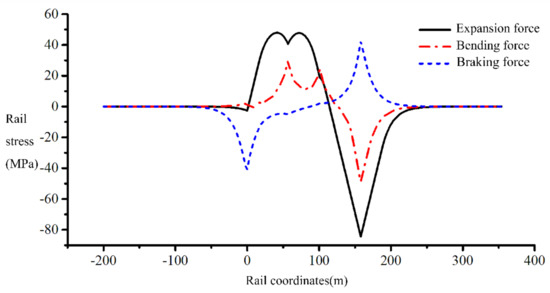
Figure 2.
The longitudinal force of the rail.
The adjacent long-span continuous beam has a significant influence on the rail expansion force at the fixed end of the steel truss beam, which should be considered. After setting a small resistance fastener, the maximum stress of the steel truss rail and the horizontal force of the bridge pier are significantly reduced under the expansion condition, but it is necessary to check the broken joint of the rail. After the small resistance fastener is installed in the bridge, the rail break value meets the requirements of the allowable value of rail breakage under difficult conditions in the specification [34].
3.2. Continuous Beam Bridge
3.2.1. Limitation of Bridge Length
The rail expansion force has a decisive influence on the bridge length limitation of the long-span railway continuous beam bridge. It is required that the maximum bridge length of the single deck expansion joint is 144 m in the bridge without the rail expansion joints, and the bridge with double-deck expansion joints. The maximum total length of the bridge is 290 m [35].
3.2.2. Track–Bridge Interaction Law
In the case of full bridge loading, the stress and deformation of the track structure on the long-span continuous beam bridge are obviously greater than that of the multi-span simply supported beam bridge. The bending force of the steel rails on the continuous beam main bridge appears as tension on both side spans and appears on the middle span as the pressure, and its maximum value appears at the side span of the main bridge and the middle of the main span. The maximum relative displacement of the rail slab appears on the top of the fixed support abutment. For continuous beam bridges, the right side of the continuous beam main bridge two-span loading and full-bridge loading are the most unfavorable conditions. When calculating the bending force and displacement of the CRTS-Ⅲ slab ballastless track seamless track on a long-span continuous beam bridge, the most unfavorable train load action length should be selected according to different check components. Under the vertical temperature gradient, the rail stress peaks all appear near the middle of the full bridge span. The increase of the vertical temperature gradient of the beam will cause the deformation of the rail and the force of the bridge pier to increase [36].
The use of low-resistance fasteners on the bridge can significantly reduce the rail deflection, displacement, and the longitudinal force of the fixed support pier top [37], but it will weaken the nonlinear constraint between the bridge and the track and make the collision effect stronger [38]. Controlling the longitudinal stiffness of the top of the pier and abutment within the range of 1.0 to 1.5 times the design value is beneficial to the force and deformation of the track and bridge structure under the action of the train load [37].
3.3. Cable-Stayed Bridge
3.3.1. Track–Bridge Interaction Model
The span of the cable-stayed bridge of high-speed railway is 32 + 80 + 112 m at the Changsha section of the Shanghai Kunming railway crossing Wuhan Guangzhou high-speed railway. The cable-stayed bridge is a single tower with double-cable planes, with a tower height of 51.8 m, a rigid connection between the tower and the beam, the main beam is a trough section, and the bridge deck is 6.6m wide, as shown in Figure 3. Assuming that there is no vertical and horizontal relative displacement between the track and the beam, the beam element with the rigid arm is used to simulate the beam, and the equivalent spring is used to simulate the longitudinal stiffness of the substructure. Without considering the sliding bearing friction, the 250 m rail on the subgrade section on both sides of the bridge is established to reduce the influence of boundary conditions. The nonlinear bar element is used to simulate the nonlinear contact between the beam and the rail. The unified finite element model of the pylon-cable-beam-adjacent span-track substructure is established, as shown in Figure 4.

Figure 3.
U-shaped beam section (unit: cm).

Figure 4.
Finite element model of cable-stayed bridge and CWR (unit: mm).
3.3.2. Track–Bridge Interaction Law
In different structural systems, the diagram of rail braking force and bending force when the train passes through the whole bridge is as shown in Figure 5 and Figure 6 [39]. The distribution law of the additional longitudinal force of the seamless track on the cable-stayed bridge is the same as that on the ordinary bridge. The change of the cable stiffness has little effect on the longitudinal interaction of the seamless track on the bridge. The influence is smaller. When designing the seamless track on the bridge, it is recommended that the influence of the rigidity changes of the stay cables and the main tower should not be considered [40,41].
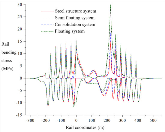
Figure 5.
Rail bending stress under vertical load.
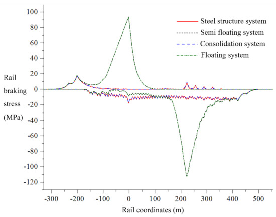
Figure 6.
Rail braking stress under train braking.
The additional force of rail expansion and contraction on the long-span railway cable-stayed bridge is obviously greater than the additional force of deflection [42,43]. When calculating the expansion and contraction force of the rails of a concrete cable-stayed bridge, it is recommended to load calculations based on the beam body heating of 15 °C and the cable heating of 40 °C [44]. In the calculation, the geometric nonlinearity and initial internal force of the cable-stayed bridge can be ignored, and the cable-stayed bridge can even be simplified as a continuous beam bridge with telescopic beams at both ends and fixed bearings in the middle of the span [45,46]. However, the influence of adjacent bridges must be considered. When the number of adjacent simply supported bridges is greater than six spans, it can be simplified as six spans [47].
When calculating the bending force of the rail, the pile foundation should be considered [48]. The load can be placed on the main span of the cable-stayed bridge and its adjacent span, or the load can be placed only on the main span of the cable-stayed bridge, and there is no need to consider changes in the direction of the train entering the bridge [45]. The structural system of the cable-stayed bridge is relatively flexible, and the rail near the middle of the span bears a large bending force [49]. When the vertical train load is loaded on the mid-span of a cable-stayed bridge, the vertical deformation and curvature of each member are greatly affected [50].
When calculating the interaction between the beam and the rail under braking, the main tower and stay cable of the cable-stayed bridge do not change the transmission mechanism of the braking force, so the existing CWR checking method on the bridge can still be used for the checking calculation [51], and the static method can be used in practical engineering application [52].
The construction of high-speed railway cable-stayed bridges in areas with high wind speeds requires consideration of the additional force on the steel rails caused by wind loads on the towers [48]. When constructing a cable-stayed high-speed railway bridge in an area where the basic wind pressure exceeds 0.5 kN·m−2, it is necessary to check the influence of the pylon on the additional force of the rail under the action of the longitudinal wind load [44].
In order to reduce the additional force on the steel rails of the cable-stayed bridge, the following methods can be adopted: (1) The longitudinal restraint of the high-speed railway cable-stayed bridge can be the consolidation of tower beams or the installation of fixed supports between tower beams, and other supports are set as longitudinal sliding support [44,48]. (2) When selecting the support arrangement of the simply supported beams at both ends of the cable-stayed bridge, the fixed support is set near the side of the cable-stayed bridge [47]. (3) The groove section can also effectively reduce the deflection of the rail [48]. (4) The installation of viscous dampers can effectively reduce the braking force of the rail when the train is braking, reduce the relative displacement of the beam and rail [40,51], and greatly reduce the longitudinal force on the top of the pier [48]. (5) A track expansion device is installed at the bridge tower, which can effectively reduce the track force near the abutment [43,44,48,49], and the supporting device provided with the beam end can effectively alleviate the unevenness of the track stiffness caused by the increase of the beam gap [43]. (6) A speed lock can be set to effectively limit the braking effect of the train. The longitudinal displacement of the lower main beam reduces the deformation of the line [45].
3.4. Arch Bridge
3.4.1. Track–Bridge Interaction Model
The span of a long-span, multi-line, tied arch continuous beam bridge on the Harbin- Qiqihar passenger-dedicated line is (77 + 3 × 156.8 + 77) m, with single-box, four-chamber box section, 4.2 m-high mid-span beam, and 1/37.33 ratio of height to span. The middle fulcrum beam is 8.6 m high, and the height span ratio is 1/18.23. The rise height of the side main span and side arch is 26 m, and the rise span ratio is 1/6, while the rise height of the middle arch is 31 m, and the rise span ratio is 1/5.03. The rise height of the side arch of the middle main span is 34 m, and the rise span ratio is 1/4.59, while the rise height of the middle arch is 39 m, and the rise span ratio is 1/4. The bridge deck is 29.4 m-wide, and four lines of ballasted track are laid on the bridge. The cross-section form is shown in Figure 7. The spatial finite element analysis model of the tied arch continuous beam composite structure bridge is established considering the concrete-filled steel tube arch rib, cross brace, suspender, beam body, pier, and track structure. The circular end CFST arch is simulated as a composite section beam composed of two kinds of materials, without considering the slip between the steel tube and concrete. The suspender is simulated by the rod element, and the suspender force is simulated by applying the initial strain. The equivalent stiffness matrix element is used to simulate the pile group foundation at the bottom of the brake pier, as shown in Figure 8.
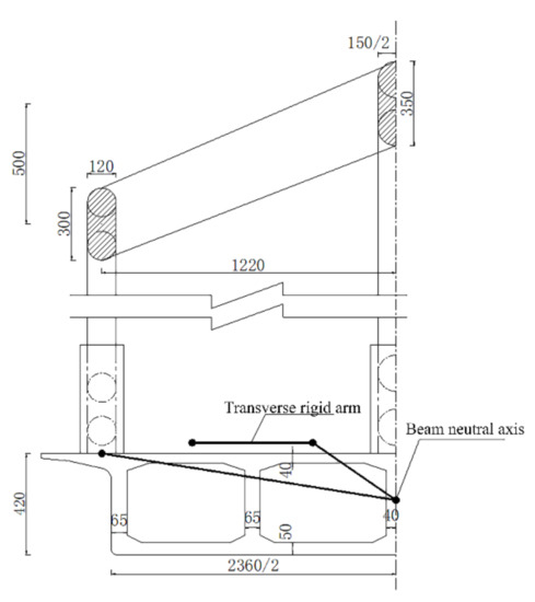
Figure 7.
Mid-span cross-section (unit: cm).
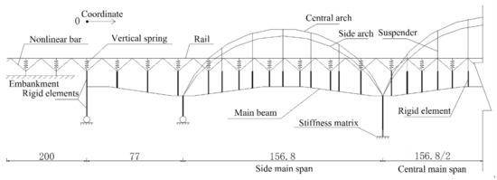
Figure 8.
Model of tied arch continuous bridge and tracks (unit: m).
3.4.2. Track–Bridge Interaction Law
Take the temperature change range of the beam body as 15 °C and take the temperature change range of the arch rib and steel suspender as 40 °C, safely. SJ is set at the arch foot of the main span on both sides of four lines. Analyze the influence of the temperature drop of the suspender and the arch rib on the temperature force of CWR on the tied arch continuous beam bridge. The results of expansion force are shown in Figure 9. ZK live load is selected as the vertical live load, the loading length is 200 m, and the loading step is 5 m. Assuming the train passes through the whole bridge in the same direction as lines 1 and 3, the results of bending force are shown in Figure 10. The braking force ratio is 0.25, and the braking force results are shown in Figure 11 [53].
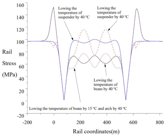
Figure 9.
Rail stress under temperature load.
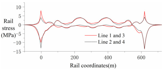
Figure 10.
Rail stress under vertical load.

Figure 11.
Rail stress under train braking.
The highest surface temperature of the track slab is 37.5~47.0 °C, and its distribution is closely related to the temperature of each place. The temperature of the track structure is relatively low near Xining and Kunming, and relatively high in Chengdu, Changsha, and southeast coastal areas.
The maximum positive temperature difference in each area of ballastless track is 15.8~19.5 °C, and its distribution is related to longitude. The positive temperature difference of the ballastless track in the western area is relatively large.
Arch bridges are considered as deck, mid-through, and through-arch bridges. When calculating the expansion force of the steel rail, the arch-assisted temperature difference of the deck arch bridge has a significant influence on the expansion force of the rail, which cannot be ignored, while the expansion force of the rail of the mid-through-arch bridge mainly depends on the expansion deformation of the main girder, and the arch bridge can be simplified in the middle of the main girder. The continuous beam with fixed support is calculated according to the ordinary bridge’s expansion force. The through-arch bridge can be simplified to the ordinary simply supported beam or continuous beam to calculate the expansion conditions. It is recommended to take 30 °C (ballastless track) or 15 °C (ballasted track) according to the temperature difference of concrete arch ribs, 25 °C (ballasted track) for steel arch ribs, and the temperature difference of cover beams, pillar piers, or booms. Take the temperature difference of the same arch rib and take the temperature difference of the beam body (15 °C) to calculate the expansion force of the rail. When calculating the bending force, the deflection condition of the deck arch bridge under half-span loading of the arch bridge is the most unfavorable. The bending force of the half-through-arch bridge is much smaller than the expansion force and can be ignored. The deflection tension of the steel rail of the through-arch bridge is small, and can also be ignored. It is recommended to arrange the load on the main span of the arch bridge, focusing on the calculation of the deflection pressure of the steel rail. When calculating the braking force, it is recommended to brake in the full span of the third-class arch bridge [54,55].
The frictional resistance of the sliding bearing has a great influence on the additional force of expansion and the additional force of rail-breaking of the long-span arch bridge–track system, and has a relatively small influence on the bending force. After considering the friction effect of the support, the additional stresses of the steel rail are reduced, and the additional horizontal force of each pier and abutment is significantly increased. The influence of the friction effect of the sliding support should be considered in the analysis of the beam–rail system [56].
To reduce the force on the piers of the long-span arch bridge when the train is braking, a certain number of speed lockers can be considered [54]. To reduce the longitudinal additional force of the steel rail on the long span through the arch bridge, it is recommended to arrange a set of one-way steel rail expansion adjusters at the left end of the continuous beam, and the switch rail is located on the left span of the arch bridge [55].
3.5. Suspension Bridge
3.5.1. Track–Bridge Interaction Model
The span of the ground-anchored suspension bridge with a double-tower continuous steel truss girder for highway and railway is (84 + 84 + 1092 + 84 + 84) m. The upper layer is equipped with an eight-lane expressway, and the lower layer is equipped with a double-line passenger-dedicated line and a double-line intercity railway, with the line spacing of 4.6 m. The width of the upper deck is 43 m, the width of the lower deck is 30 m, and the beam height is 16 m. The mid-span section of the bridge is shown in Figure 12. The north tower is 203 m high, and the south tower is 191 m high. Both towers have box sections. The side span of the main girder is 350 m (refer to Figure 13). Considering the main cable, suspender, steel truss, orthotropic plate, and the adjacent bridge structure, the model of the interaction between suspension bridge and four tracks is established. Only considering vertical and transverse constraints at the joint of the main truss and the crossbeam of tower, no constraint in the direction of the bridge is considered. The vertical and transverse displacements are constrained at moveable bearings. Six equally stiff springs are used to simulate the pier group foundation at the bottom of the tower. The adjacent bridges will adopt the option of a continuous bridge. The fixed bearing is set at the central pier, and moveable bearings at the other piers. Nonlinear bar elements are used to simulate the ballast track without considering the influences of the track–bridge transverse displacement on the track–bridge longitudinal interaction. By using the linear spring to simulate the vertical stiffness of the fastener, the model of longitudinal force on CWR on a suspension bridge is partly shown in Figure 14.
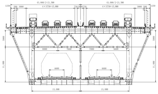
Figure 12.
The main beam section (unit: mm).
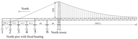
Figure 13.
The layout of a suspension bridge (unit: mm).
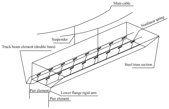
Figure 14.
Model of longitudinal force.
3.5.2. Track–Bridge Interaction Law
To study the influences on force and deformation of the bridge–track system due to the temperature differences on the main beam, tower, main cable, and suspenders, four kinds of cases are set as follows:
Case I: Temperatures decrease by 25 °C on the bridge and 48 °C on tracks.
Case II: Temperatures decrease by 15 °C on towers and 48 °C on tracks.
Case III: Temperatures decrease by 40 °C on the main cable and 48 °C on tracks.
Case IV: Temperatures decrease by 40 °C on suspenders and 48 °C on tracks.
The results of all cases are shown in Figure 15.
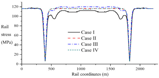
Figure 15.
Influences on rail stress due to the temperature differences on components.
Assuming the four lines are loaded simultaneously, and the two passenger lines adopt the load of 0.8 UIC and the two intercity lines adopt the load of 0.6 UIC, the track stress, track longitudinal displacement, beam–track relative displacement, and vertical track displacement are calculated (see Figure 16). Assuming the two lines braking simultaneously are considered and the braking force ratio is 0.25, the envelope diagram of track stress and beam–track relative displacement is shown in Figure 17 [57].
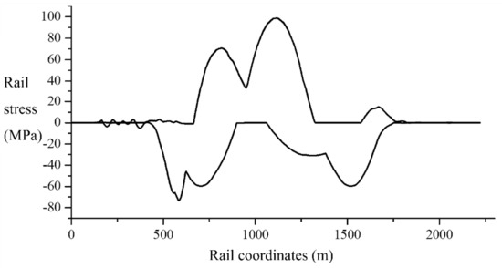
Figure 16.
Results of bending force.
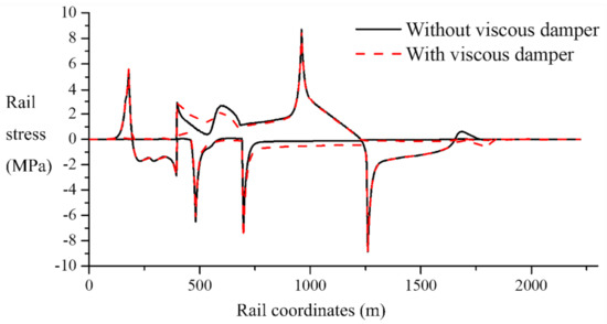
Figure 17.
Results of braking force.
The stiffness of the large-span suspension bridge under the action of high-speed trains can meet the requirements of safety and ride comfort of high-speed trains [58]. Since the vertical stiffness of the suspension bridge is relatively small, the bending force replaces the expansion force and becomes the controlling load of the rail [57,59].
When calculating the deflection and breaking force of a long-span railway suspension bridge, the initial internal force of the suspension bridge and the large deformation effect of the suspension bridge have obvious effects. When calculating the braking force, the initial internal force of the suspension bridge has a significant impact, the large deformation effect of the suspension bridge is significant and cannot be ignored, while for the main cable sag, the degree effect has little influence on the beam–rail interaction and can be ignored [60].
By installing a rail expansion device at the end of a long-span suspension bridge, the stress on the rail at the beam end and the horizontal force on the top of the brake pier can be greatly reduced [57,59], and the viscous damper has little effect on the track stress and the relative displacement of the beam and rail [57].
4. Special Problems of Track–Bridge Interaction
4.1. Earthquake Load
The maximum longitudinal force of rail at the joint of the long-span bridge under earthquake action is much larger than that calculated according to the expansion condition of the current specification. It is suggested that the index of seismic force calculation of rail should be added to the CWR laid on the railway bridge passing through the earthquake area [61].
The analysis shows that the track restraint has an obvious influence on the longitudinal earthquake resistance of the railway bridge [62] and the low-order longitudinal natural frequency of the long-span bridge structure [54,61], and reduces the seismic response of the structure [62]. The existence of the track can improve the fundamental frequency of the system to a certain extent, play the role of energy dissipation, reduce the seismic response of the bridge and pier [63], enhance the integrity of the bridge span structure along the bridge direction, reduce the traveling wave effect response of the beam end relative displacement, and increase the traveling wave effect response of the truss axial force [64]. It is suggested that the influence of track constraints should be considered in the seismic design of railway bridges crossing seismic areas, otherwise the bridge structure design will be too conservative [54,61].
When studying the longitudinal seismic response of CWR on the long-span continuous beam bridge, the length of the calculation section on both ends of the subgrade should be 100 m [61], and the reasonable length of the subgrade on both ends of the simply supported beam bridge should be 90 m [65]. The spectrum characteristics of the seismic wave used in the analysis should be consistent with the spectrum characteristics of the soil at the bridge site. Within the range of a reasonable damping ratio, the damping ratio has little influence on the seismic response of the structure, which can be taken as 0.05 [54].
The seismic response of the structure is investigated according to the 8-degree design earthquake (Ag = 0.3 g). When determining the time history of ground motion acceleration, the normalized response spectrum is imported into the SIMQKE_GR program developed by UC Berkeley to generate artificial seismic wave W1. Figure 18 is the envelope diagram of the rail stress response of the 156 m New Yellow River Bridge under uniform excitation and the seismic passage effect (apparent wave velocity of 200 m/s). It can be seen that for the long-span simply supported beam bridge, the traveling wave effect increases the risk of falling beams and the possibility of collision, weakens the following ability of the track and the bridge in the middle of the beam span, and greatly improves the stress response amplitude of the rail at the end of the beam span, which has adverse effects on the seismic performance of the bridge and the track [64].
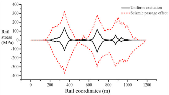
Figure 18.
Envelope diagram of rail stress response.
The traveling wave effect has a great influence on the seismic response of the long-span railway continuous beam arch composite bridge. With the increase of the apparent wave velocity, the bending moment of the arch rib increases, and the axial force first decreases and then increases [66]. For the continuous beam bridge, compared with uniform excitation, the longitudinal force of the rail increases, and the force of the brake pier decreases under the longitudinal traveling wave effect [63]. If the seismic passage effect is ignored or the seismic wave propagation velocity is assumed to be inappropriate, this difference may lead to significant underestimation or overestimation of the random vibration response of bridges and trains [67].
The viscous dampers with reasonable parameters can effectively reduce the vibration. The viscous damper has a significant damping effect on the bending moment and shear force at the pier bottom, relative displacement of the pier beam [68], displacement of the beam end [69], and longitudinal force [49] at the pier top, but has a relatively small effect on rail stress and rail deformation [48]. The speed-locking device can significantly reduce the displacement of the fixed pier top and the internal force of the pier bottom of the long-span railway continuous beam arch composite bridge [66]. The larger resistance of the ballast bed is beneficial to the seismic resistance of bridge piers [62]. After the small resistance fasteners are laid on the long-span bridge, the maximum longitudinal force of the rail at the beam joint will be effectively reduced during the earthquake [54,61].
4.2. Complex Temperature Load
For bridge structures, the temperature field generated by sunlight is a three-dimensional transient problem, but the existing research shows that the temperature distribution along the bridge direction is very similar under the action of sunlight, and the slight change of temperature along the bridge axis can be ignored in engineering. Therefore, the sunshine temperature field problem of the bridge structure can be simplified as a two-dimensional transient nonlinear problem on the section. The temperature effects of solar radiation, convective heat transfer, and radiation heat transfer are transformed into radiation heat flux by using ANSYS. Using the boundary condition function of the ANSYS load table, the heat flux is stored in the table, indexed by time, temperature, and coordinates, and the table is used as the boundary condition for the loading calculation.
The maximum error between the calculated temperature and the measured temperature is 1.8 °C, and the average relative error is 3.6%. According to this model, based on the thermodynamic simulation analysis, the vertical temperature load formula of the ballastless track suitable for typical areas in China is fitted:
where t is the temperature of the track slab at different depths, °C; x is the depth from the track slab surface, m; a (b) is the regional adjustment coefficient of the fitted positive (negative) temperature gradient, as shown in Table 1.

Table 1.
Adjustment coefficients of typical regions in China.
The surface temperature of the ballastless track changes dramatically with the environment temperature and time, its internal temperature changes have a certain lag in time, and the change amplitude decreases rapidly with the increase of depth. The stronger the sunshine is, the higher the wind speed is, and the greater the vertical temperature gradient is. The maximum positive temperature gradient of the ballastless track in China occurs from 13:30 to 16:00 in May to August, and the average maximum vertical positive temperature difference is 17.0 °C. The maximum negative temperature gradient occurs from 5:00 to 5:30 in January, and the average maximum negative temperature difference is 8.7 °C. The surface temperature of the ballastless track in Chengdu, Changsha, and southeast coastal areas exceeds 45 °C in summer, and the lowest surface temperature of the track slab in Urumqi and Harbin is lower than −16 °C in winter. For central China, the vertical temperature gradient of the track slab is −2~10 °C [70,71].
With the increase of the uneven temperature difference of the bridge, the additional expansion force of the rail decreases, and the longitudinal displacement of the rail also decreases. According to the current code, the expansion force of the rail calculated at 20 °C is 1.3 times the rail stress under sunlight. However, the increase of the uneven temperature difference of the bridge will affect the ride comfort of CWR on the bridge. It is suggested to consider the influence of the uneven distribution of the bridge temperature to make it closer to the real stress state of the bridge [72,73].
Increasing the thickness of the base plate will help to improve the stress of the rail. Under the action of sunlight, the stress of the rail is proportional to the transparency coefficient of the atmosphere. The light color coating on the pavement and keeping the smoothness will help to reduce the stress of the rail [72].
4.3. Shrinkage and Creep
The span of a long-span, prestressed concrete, continuous rigid-frame bridge with a double-track ballastless track is (72 + 128 + 72) m. The bridge adopts a single-box single-chamber box section, the beam body is C55 concrete, the deck width is 12 m, and the mid-span beam height is 4.8 m (as shown in Figure 19). The pier adopts a rectangular thin-walled pier, which is made of C40 concrete. The heights of P1 and P2 piers are 96 and 102 m, respectively. The relative humidity of curing is 70.
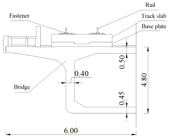
Figure 19.
Beam cross-section (unit: m).
The beam element with a rigid arm is used to simulate the beam body, and the beam pier is rigidly connected. According to the actual situation of pier modeling, the pier bottom is set to be consolidated.
A double-line ballastless track is laid on the bridge without a rail expansion regulator, and the rail is 60 kg/m. The rail on the 200 m subgrade is built on both sides of the abutment. The linear spring is used to simulate the vertical stiffness (50 MN/m), and the fastener resistance is used as the longitudinal resistance of the line. The relationship between the longitudinal resistance of the line (kN/m) and the relative displacement of the beam rail (mm) can be expressed as follows:
When building the bridge structure model, the construction stages of formwork erection, concrete pouring, tension prestress, and demolding are simulated accurately according to the actual situation, and the simulation model of the prestressed concrete, continuous rigid-frame bridge–track system is established, as shown in Figure 20.

Figure 20.
Simulation model for the track–bridge interaction.
Based on the shrinkage creep model proposed by the China Railway code (TB10002.3–2005), China Highway code (JTG D62–2004), and Eurocode 2, the concrete material properties are defined as a time-dependent function.
When extracting the force and deformation of key components, only the shrinkage and creep conditions are extracted. The force and deformation of the system after 120 days of track laying are calculated (for the sake of simplification, the influence of rail change, fastener change, and stress release are not considered), as shown in Figure 21.
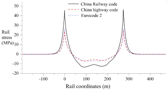
Figure 21.
Rail stress due to shrinkage and creep model under different codes.
Under the action of shrinkage and creep, the rail stress and displacement of the long-span continuous steel frame bridge are basically symmetrical. The maximum value of rail stress appears near the abutment, and the maximum value of rail vertical displacement appears in the middle of the span [74].
With the extension of the service time, the stress and deformation of the system increase gradually, which increases rapidly in the first five years, then gradually slows down, and gradually stabilizes after 10 years of track laying [74,75,76]. The additional force caused by concrete shrinkage and creep is much larger than that caused by bending and braking. It is not safe to ignore the influence of concrete shrinkage and creep on rail longitudinal force [39,75].
Compared with the rail stress and deformation under the Eurocode shrinkage and creep mode, the calculation results under the Chinese Railway code shrinkage and creep mode are larger. When selecting the standard calculation, we should consider the situation of the calculation object and select the applicable standard [74,75,77,78]. Based on the short-term concrete creep test data, a creep prediction model suitable for practical engineering is established. As the basis of structural calculation, the creep development of the actual structure can be more accurately predicted, and the prediction accuracy of long-term shrinkage and creep of the long-span railway concrete bridge can be improved [79].
The results show that the additional force of shrinkage and creep is more sensitive to the beam storage time, the rail stress and vertical displacement decrease with the increase of the beam storage time, and the beam storage time has little effect on the horizontal force on the pier top [74,77]. After using the small resistance fastener, the stress of the rail can be obviously improved, the additional force of the rail near the peak value is significantly reduced, and the additional force of the rail shrinkage and creep and the additional force of the rail expansion can be significantly reduced [75]. Strengthening the curing of concrete can also reduce the effect of shrinkage and creep of prestressed concrete on the stress and deformation of the rail. The rail stress, vertical displacement, and pier top horizontal force decrease rapidly with the increase of the concrete curing relative humidity [74].
4.4. Superposition of Multiple Loads
The longitudinal force of the rail and horizontal force of the pier top of the (32 + 80 + 112) m cable-stayed bridge of the Shanghai–Kunming railway crossing Wuhan–Guangzhou high-speed railway in Changsha section are calculated by the load step method considering the loading history.
Bending–braking force is the combined action of bending force and braking force. The load step method is used to analyze the braking condition of the train on the bridge step-by-step. The calculated results are compared with the algebraic sum of the braking force and bending force.
Bending force when temperature rises (drops): After the temperature rise (drop) of the beam, the train passes through the bridge. In the calculation, the first load step is to increase (decrease) the temperature of the beam, and from the second load step, the bending force of the train passing through the bridge is analyzed step-by-step. The calculated results are compared with those of “± expansion force + bending force”.
Bending–braking force when temperature rises (drops): The first load step is to increase (decrease) the temperature of the beam, and the second load step is to analyze the situation of the train braking on the bridge step-by-step. The calculated results are compared with those of “± expansion force + bending force + braking force”.
The extreme values of rail longitudinal force under various loads are summarized in Table 2.
Table 2.
Extreme values of rail longitudinal force considering loading history (unit: MPa).
When checking the rail, the longitudinal force of each rail can be calculated separately and then added. The error between the result and the result of the load step method considering the loading history is usually less than 10%, and it is generally safe [27,29,80].
5. Conclusions
Since 1963, when China first laid a CWR on the Liulihe bridge of the Beijing–Guangzhou railway, systematic theoretical and experimental research on the track–bridge interaction has been carried out in China. The track–bridge interaction model is widely used for its strong expansibility and comprehensiveness. Especially in recent years, with the establishment of the theoretical framework of the track–bridge interaction, more and more attention has been paid to this aspect. At present, the development of the track–bridge interaction can be concluded as the following aspects:
- (1)
- The theory of the track–bridge interaction has been developed with the improvement of the theories related to each part of the track and bridge system, which are more consistent with the measured results. Many practical problems of the track on the bridge can be studied by using the finite element model for refinement modeling. In bridge modeling, the finite element method and the modal superposition method are widely used due to their accuracy and efficiency. For some applications, the nonlinear characteristics of the structure can be considered in the beam–return interaction model.
- (2)
- The track–bridge interaction has shown its advantages in various engineering applications. For a large-span bridge of a high-speed railway under design or in service, it has become a common practice to evaluate the bridge by using the track–bridge interaction. Through the stress analysis of the track–bridge system, the actual service condition of the bridge can be better described, and the fatigue life assessment of the bridge can be more reliable. The longitudinal force of the rails of the five large-span railway bridges mentioned in the paper is obviously larger than that of the medium- and small-span railway bridges. Therefore, to control the force and deformation of the system, the rail expansion regulator, viscous damper, speed lock, small resistance fastener, or the support type and section type can be changed according to the actual situation.
- (3)
- Considering the loading history, the track–bridge interaction theory is more refined, which makes the calculation results more consistent with the measured results. With the development of experimental methods and statistics, seismic science, wind engineering, and other related disciplines, system excitation can be described with high precision by measured data or more and more accurate models, and numerical algorithms also show strong large-scale computing ability. It can be used to evaluate the safety of the track–bridge system under special excitations such as earthquake load, complex temperature load, shrinkage and creep load, and multiple-load superposition.
Author Contributions
Conceptualization, B.Y. and W.K.; methodology, B.Y., W.K. and R.G.; search and analysis, B.Y., W.K. and H.X.; writing—original draft preparation, B.Y. and J.H.; writing—review and editing, W.K. and R.G.; supervision, W.K. and H.X. All authors have read and agreed to the published version of the manuscript.
Funding
This research was funded by the National Natural Science Foundation of China, grant number 52278470; and the Natural Science Foundation of Hunan Province, grant number 2022JJ30741.
Institutional Review Board Statement
Not applicable.
Informed Consent Statement
Not applicable.
Data Availability Statement
Data are contained within the article.
Conflicts of Interest
The authors declare no conflict of interest.
References
- TB 10002-2017; Code for Design on Railway Bridge and Culvert. China Railway Publishing House: Beijing, China, 2017.
- TB 10015-2012; Code for Design of Railway Continuously Welded Rail. China Railway Publishing House: Beijing, China, 2013.
- Yan, B. Interaction between Continuously Welded Rail and Medium/Small Bridges of High-Speed Railway. Ph.D. Thesis, Central South University, Changsha, China, 2013; p. 174. [Google Scholar]
- International Union of Railways. Braking and Acceleration Force on Bridges-Braking and Starting Tests on Track; International Union of Railways: Paris, France, 1969. [Google Scholar]
- International Union of Railways. Braking and Acceleration Force on Bridges and Interactions between Track and Structures-Thermal Phenomena in the Interaction between CWR and Bridges in the Case of a DB Pre-Stressed Concrete Bridge with Ballasted Track; International Union of Railways: Paris, France, 1984. [Google Scholar]
- German Standard DS899/59; Special Procedures on Railway Shinkansen Bridge. Bridge Research Institute of Railway Bridge Authority: Berlin, Germany, 1991.
- UIC. UIC 774-3 Track/Bridge Interaction. Recommendations for Calculations; International Union of Railways: Paris, France, 2001. [Google Scholar]
- EN 1991-2:2003; Eurocode I: Actions On structures-Part 2: Traffic Loads on Bridges. European Committee for Standardization: Brussels, Belgium, 2003.
- Boryevko, B. The Problem of Railway Bridge Bearing Braking Force; Bridge Translation: Newmarket, ON, Canada, 1964. [Google Scholar]
- Fryba, L. Quasi-Static Distribution of Braking and Starting Forces in Rail and Bridges. Rail Int. 1974, 11, 698–716. [Google Scholar]
- Duan, C. Experimental study on additional bending force of CWR rail on ballasted reinforced concrete beam bridge. J. Chang. Railw. Univ. 1984, 4, 7–18. [Google Scholar]
- Wang, G. Redistribution of expansion force and deformation of CWR on bridge with beam temperature. Railw. Stand. Des. Commun. 1984, 4, 8–15. [Google Scholar]
- Bu, Y. Research on Longitudinal Force Transfer Mechanism of High Speed Railway Bridge. Ph.D. Thesis, Southwest Jiaotong University, Chengdu, China, 1998. [Google Scholar]
- Yin, C. Nonlinear Static and Dynamic Analysis and Simulation of Longitudinal Additional Force of Railway Bridge. Ph.D. Thesis, Academy of Railway Sciences, Beijing, China, 2000. [Google Scholar]
- Yin, C. Dynamic response analysis of railway bridge under longitudinal braking of train. China Railw. Sci. 2000, 21, 10–20. [Google Scholar]
- Yin, C. Nonlinear dynamic simulation technology of railway bridge longitudinal force. China Railw. Sci. 2001, 5, 125–130. [Google Scholar]
- Yang, M.; Xing, J. Research on mechanical calculation model of interaction between track structure and bridge. China Railw. Sci. 2001, 3, 60–65. [Google Scholar]
- Xu, Q.Y.; Zhou, X.L.; Zeng, Z.P.; Yang, X.L. Mechanics Model of Additional Longitudinal Force Transmission Between Bridges and Continuously Welded Rails with Small Resistance Fasteners. J. Cent. South Univ. Technol. 2004, 11, 336–339. [Google Scholar] [CrossRef]
- Xu, Q.; Chen, X. Additional Longitudinal Forces Transmission Between Bridges and Continuously Welded Rails with Small Resistance Fasteners. J. Traffic Transp. Eng. 2003, 3, 25–29. [Google Scholar] [CrossRef]
- Xu, Q.; Wang, P.; Qu, X. Computation Model of Rupture Force Between Continuously Welded Rail and High-Speed Railway Bridge. J. Traffic Transp. Eng. 2006, 6, 23–26. [Google Scholar]
- Xu, Q.; Chen, X.; Li, S. Research on longitudinal additional force of CWR on high speed railway bridge. China Railw. Sci. 2006, 3, 8–12. [Google Scholar]
- Xu, Q. Three Dimensional Finite Element Static and Dynamic Analysis of Longitudinal Additional Force of CWR on High Speed Railway Bridge. Ph.D. Thesis, Central South University, Changsha, China, 2005; p. 170. [Google Scholar]
- Ruge, P.; Birk, C. Longitudinal Forces in Continuously Welded Rails on Bridgedecks Due to Nonlinear Track–Bridge Interaction. Comput. Struct. 2007, 85, 458–475. [Google Scholar] [CrossRef]
- Ruge, P.; Widarda, D.R.; Schmälzlin, G.; Bagayoko, L. Longitudinal Track–Bridge Interaction Due to Sudden Change of Coupling Interface. Comput. Struct. 2009, 87, 47–58. [Google Scholar] [CrossRef]
- Lou, P.; Yu, Z.; Au, F.T.K. Rail–Bridge Coupling Element of Unequal Lengths for Analysing Train–Track–Bridge Interaction Systems. Appl. Math. Model. 2012, 36, 1395–1414. [Google Scholar] [CrossRef]
- Yan, B.; Dai, G. Analysis of high speed railway beam rail interaction considering loading history. J. China Railw. Soc. 2014, 36, 75–80. [Google Scholar]
- Wang, P.; Xie, K. Simplification of calculation model and method of CWR on continuous rigid frame bridge. J. Cent. South Nat. Sci. Ed. 2015, 46, 2735–2743. [Google Scholar]
- Zhang, J.; Wu, D.; Li, Q. Loading-History-Based Track–Bridge Interaction Analysis with Experimental Fastener Resistance. Eng. Struct. 2015, 83, 62–73. [Google Scholar] [CrossRef]
- Dai, G.; Zheng, R.; Chen, G. Research on calculation method of rail expansion additional force of CWR on bridge. J. Railw. Eng. 2017, 34, 35–40. [Google Scholar]
- Luo, J.; Zeng, Z. A Novel Algorithm for Longitudinal Track-Bridge Interactions Considering Loading History and Using a Verified Mechanical Model of Fasteners. Eng. Struct. 2019, 183, 52–68. [Google Scholar] [CrossRef]
- Guo, W.; Hu, Y.; Gou, H. Simplified Seismic Model of CRTS II Ballastless Track Structure on High-Speed Railway Bridges in China. Eng. Struct. 2020, 211, 110453. [Google Scholar] [CrossRef]
- Yu, X.; Deng, Y.; Yan, B. Case Study of the 156 M Simply Supported Steel Truss Railway Bridge. Struct. Eng. Int. J. Int. Assoc. Bridge Struct. Eng. IABSE 2017, 27, 563–568. [Google Scholar] [CrossRef]
- TB10015-2012; Design Specification of Railway Seamless Line. China Railway Publishing: Beijing, China, 2012.
- Yu, X.; Yin, X.; Yan, B. Influence of adjacent spans on long-span steel truss bridge track system. J. South China Univ. Technol. Nat. Sci. Ed. 2016, 44, 137–142. [Google Scholar]
- Ramos, Ó.R.; Schanack, F.; Carreras, G.O. Bridge Length Limits Due to Track-Structure Interaction in Continuous Girder Prestressed Concrete Bridges. Eng. Struct. 2019, 196, 109310. [Google Scholar] [CrossRef]
- Li, H. Research on mechanical characteristics of continuous rigid frame bridge track under temperature gradient. Railw. Constr. Technol. 2019, 1, 58–61. [Google Scholar]
- Zhang, P.; Gui, H.; Lei, X. Deflection and displacement of CRTS III slab ballastless track on bridge under train load. J. Transp. Eng. 2018, 18, 61–72. [Google Scholar]
- Tu, P.; Zhou, W.; Yan, B. Research on collision effect of Heavy Haul Railway Long Span Rigid Frame Bridge Track System. J. Railw. Sci. Eng. 2017, 14, 2146–2153. [Google Scholar]
- Dai, G.; Yan, B. Research on interaction between high speed railway cable stayed bridge and CWR. J. Civ. Eng. 2013, 46, 90–97. [Google Scholar]
- Zhan, W. Research on Design and Calculation Method of CWR on Cable Stayed Bridge. Ph.D. Thesis, Southwest Jiaotong University, Chengdu, China, 2010; p. 78. [Google Scholar]
- Wang, P.; Zhao, W.; Chen, R.; Xiao, J. Bridge-Rail Interaction for Continuous Welded Rail on Cable-Stayed Bridge Due to Temperature Change. Adv. Struct. Eng. 2013, 16, 1347–1354. [Google Scholar] [CrossRef]
- Zhang, H. Longitudinal force analysis of ballastless track on Long Span Hybrid Girder cable stayed bridge. Railw. Archit. 2020, 60, 104–107+117. [Google Scholar]
- Cai, X.; Tian, C.; Wang, T. Mechanical properties and structural design of CWR for long-span bridges. High Speed Railw. Technol. 2020, 11, 73–79. [Google Scholar]
- Yan, B.; Dai, G.; Dong, L. Design Parameters of Track-Bridge Interaction on Passenger Dedicated Line Cable-Stayed Bridge. J. Traffic Transp. Eng. 2012, 12, 31–37. [Google Scholar]
- Wang, P.; Hao, L.; Wei, X.; Xiao, J. Analysis of longitudinal force law of CWR on railway cable stayed bridge. J. Transp. Eng. 2013, 13, 27–32. [Google Scholar]
- Xie, K.; Zhao, W.; Cai, X.; Wang, P.; Zhao, J. Interaction Between Track and Long-Span Cable-Stayed Bridge: Recommendations for Calculation. Math. Probl. Eng. 2020, 2020, 5463415. [Google Scholar] [CrossRef]
- Dai, G.; Yan, B. Longitudinal Forces of Continuously Welded Track on High-Speed Railway Cable-Stayed Bridge Considering Impact of Adjacent Bridges. J. Cent. South Univ. 2012, 19, 2348–2353. [Google Scholar] [CrossRef]
- Yan, B.; Dai, G. CWR Longitudinal Force of Cable-Stayed Bridge of High-Speed Railway. J. China Railw. Soc. 2012, 34, 83–87. [Google Scholar]
- Yan, B.; Xie, H.; Pan, W. Characteristics of Interaction between Tracks and Long-Span Cable-Stayed Bridge with Steel-Concrete Composite Beam. J. Railw. Eng. Soc. 2019, 36, 11–16. [Google Scholar]
- Zhu, Z.; Yan, M.; Li, X. Research on deformation adaptability of long span cable stayed bridge ballastless track structure. China Railw. Sci. 2019, 40, 16–24. [Google Scholar]
- Zhan, W.; Wang, P.; Cao, Y. Calculation of Braking Force of Continuous Welded Rail on Large-Span Steel Truss Cable-Stayed Bridge. J. Southwest Jiaotong Univ. 2012, 47, 361–366. [Google Scholar]
- Yan, Y.; Wu, D.; Li, Q. Research on dynamic interaction between beam and rail of railway cable stayed bridge under train braking. China Railw. Sci. 2019, 40, 31–38. [Google Scholar]
- Yan, B.; Dai, G.; Guo, W.; Xu, Q.Y. Longitudinal Force in Continuously Welded Rail on Long-Span Tied Arch Continuous Bridge Carrying Multiple Tracks. J. Cent. South Univ. 2015, 22, 2001–2006. [Google Scholar] [CrossRef]
- Wei, X. Research on longitudinal beam rail interaction and seismic response of CWR on Railway arch bridge. Ph.D. Thesis, Southwest Jiaotong University, Chengdu, China, 2014; p. 176. [Google Scholar]
- Xie, K.; Su, Q.; Wang, M. Design of CWR on through arch bridge and analysis of influencing factors of longitudinal force. Railw. Archit. 2018, 58, 98–101. [Google Scholar]
- Liu, W.; Dai, G.; Qin, H. Influence of sliding bearing friction effect on beam rail interaction of long span high speed railway bridge. J. Cent. South Univ. Nat. Sci. Ed. 2019, 50, 627–633. [Google Scholar]
- Yan, B.; Zhang, G.; Han, Z.; Lou, P. Longitudinal Force of Continuously Welded Rail on Suspension Bridge with Length Exceeding 1000 M. Struct. Eng. Int. 2019, 29, 390–395. [Google Scholar] [CrossRef]
- Li, X.; Liu, D.; Jin, Z. Analysis of vehicle line bridge coupling vibration of long span railway suspension bridge. Steel Struct. 2010, 25, 6–12. [Google Scholar]
- Yan, B.; Gan, R.; Zhang, G.; Zeng, Z. Study on longitudinal force distribution of CWR on kilometer level railway suspension bridge. Acta Sin. 2021, 43, 130–135. [Google Scholar]
- Xie, K.; Zhao, W.; Cai, X.; Liu, H.; Zhang, H. Influence of initial internal force and geometric nonlinearity of suspension bridge on beam rail interaction. J. Transp. Eng. 2020, 20, 82–91. [Google Scholar]
- Yan, M.; Wei, X.; Wang, P. Study on longitudinal seismic response of CWR on long span bridge. Acta Sin. 2014, 36, 96–102. [Google Scholar]
- Huang, Y.; Yan, G.; Liu, L. influence of track restraint on longitudinal seismic response characteristics of railway bridges. J. China Railw. Soc. 2002, 5, 124–128. [Google Scholar]
- Yan, B.; Dai, G.; Wei, B. Rail interaction of high speed railway continuous beam bridge considering seismic traveling wave effect. Vib. Impact 2014, 33, 87–90. [Google Scholar]
- Yu, X.; Yin, X.; Yan, B. Study on seismic response characteristics of long span simply supported steel truss bridge track system. J. China Railw. Soc. 2017, 39, 111–116. [Google Scholar]
- Zhang, Y.; Jiang, L.; Zhou, W.; Feng, Y.; Tan, Z.; Chai, X. Study of Bridge-Subgrade Longitudinal Constraint Range for High-Speed Railway Simply-Supported Beam Bridge with CRTSII Ballastless Track Under Earthquake Excitation. Constr. Build. Mater. 2020, 241, 118026. [Google Scholar] [CrossRef]
- Dai, G.; Yu, W. Seismic Response and Cushioning Research of Long-Span Railway Continuous Beam-Arch Bridge. J. Huazhong Univ. Sci. Technol. Nat. Sci. Ed. 2015, 2015, 19–23. [Google Scholar]
- Zeng, Z.; Zhao, Y.; Xu, W.; Yu, Z.W.; Chen, L.K.; Lou, P. Random Vibration Analysis of Train-Bridge Under Track Irregularities and Traveling Seismic Waves Using Train-Slab Track-Bridge Interaction Model. J. Sound Vib. 2015, 342, 22–43. [Google Scholar] [CrossRef]
- Liu, Y.; Lin, P.; He, Z. Research on seismic reduction of long span continuous steel truss flexible arch bridge of high speed railway. J. Appl. Mech. 2019, 36, 666–673. [Google Scholar]
- Ruan, H.; Qu, A.; He, Y.; Li, L.A. Study of Structural Seismic Response Characteristics of Long Span Rail-cum-Road Steel Truss Girder Cable-Stayed Bridges. Bridge Constr. 2015, 45, 32–38. [Google Scholar]
- Yan, B.; Dai, G.; Su, H. Prediction model of vertical temperature gradient of track slab based on meteorological parameters. J. South China Univ. Technol. Nat. Sci. Ed. 2014, 42, 9–13. [Google Scholar]
- Yan, B.; Liu, S.; Dai, G. Nonlinear temperature gradient and temperature load mode of ballastless track in typical areas of China. Acta Sin. 2016, 38, 81–86. [Google Scholar]
- Dai, G.; Zheng, P.; Yan, B.; Xiao, X.N. Longitudinal force of CWR on box girder bridge under sunshine. J. Zhejiang Univ. Eng. Ed. 2013, 47, 609–614. [Google Scholar]
- Liu, K. Study on the Interaction between CWR on Bridge and CRTs I Slab Ballastless Track under Complex Temperature. Ph.D. Thesis, Beijing Jiaotong University, Beijing, China, 2016; p. 137. [Google Scholar]
- Yan, B.; Pan, W.; Meng, Y.; Xu, Q. Mechanical characteristics of Railway Continuous Rigid Frame Bridge Track System under shrinkage and creep. J. China Railw. Soc. 2017, 39, 99–103. [Google Scholar]
- Liu, C. Study on the Interaction between Beam and Rail of Cable Stayed Bridge Considering the Effect of Shrinkage and Creep. Ph.D. Thesis, Civil Engineering of Central South University, Changsha, China, 2012. [Google Scholar]
- Li, M. Research on shrinkage and creep of steel-concrete composite girder of long-span high-speed railway cable-stayed bridge. Railw. Surv. 2021. [Google Scholar]
- Liu, Z. Influence of Shrinkage and Creep and Sunshine Temperature Difference on Longitudinal Force of High Speed Railway Continuous Beam Bridge Rail. Ph.D. Thesis, Bridge and Tunnel Engineering of Central South University, Changsha, China, 2012. [Google Scholar]
- Zhao, G. Research on Creep Deformation of Long Span Continuous Rigid Frame Bridge with Ballastless Track. Ph.D. Thesis, Southwest Jiaotong University, Chengdu, China, 2009; p. 87. [Google Scholar]
- Chen, Y. Study on calculation method of shrinkage and creep of long span railway concrete cable stayed bridge. World Bridge 2020, 48 (Suppl. S1), 89–93. [Google Scholar]
- Shi, L.; Wu, D.; Li, Q. Analysis on Stress of Track on Bridge Considering Loading History and Track-bridge Interaction. J. China Railw. Soc. 2016, 38, 105–111. [Google Scholar]
Publisher’s Note: MDPI stays neutral with regard to jurisdictional claims in published maps and institutional affiliations. |
© 2022 by the authors. Licensee MDPI, Basel, Switzerland. This article is an open access article distributed under the terms and conditions of the Creative Commons Attribution (CC BY) license (https://creativecommons.org/licenses/by/4.0/).