Article

5G Based on MNOs for Critical Railway Signalling Services: Future Railway Mobile Communication System

by
Ana González-Plaza
1,2,*,
Rafael Gutiérrez Cantarero
1,*,
Rafael B. Arancibia Banda
1 and
César Briso Rodríguez
2
1
Ingeniería y Economía del Transporte S.M.E. M.P., S.A, Ineco, 28036 Madrid, Spain
2
Escuela Técnica Superior de Ingeniería y Sistemas de Comunicación, Universidad Politécnica de Madrid (UPM), 28031 Madrid, Spain
*
Authors to whom correspondence should be addressed.
Appl. Sci. 2022, 12(18), 9003; https://doi.org/10.3390/app12189003
Submission received: 18 August 2022 / Revised: 31 August 2022 / Accepted: 2 September 2022 / Published: 8 September 2022
(This article belongs to the Special Issue 5G Network Planning and Design)

Abstract

:
This paper describes the prototype and tests carried out to demonstrate the feasibility of implementing 4G/5G systems based on mobile network operators (MNOs) to transmit signalling critical data for railway systems as part of a possible solution for the Future Railway Mobile Communication System (FRMCS). This communication system design is performed from a protocol-stack perspective, introducing the KPIs for the physical layer (RSRP, RSRQ and SINR), network layer (latency and jitter) and application layer (signalling communication timeout). The analysis focuses on the characterisation of signalling critical railway data to assess the data traffic behaviour in a telecommunications laboratory. Finally, the study validates the approach in a realistic railway environment.

1. Introduction

Railway communication systems are preparing for a significant paradigm shift with the standardisation of the Future Radio Mobile Communication System (FRMCS) [1] and the introduction of 5G to the railway sector. FRMCS opens the use of the mobile network to new applications such as signalling-critical data, Mission Critical Push-To-Talk (MCPTT) or Operational Cybersecurity. On its side, 5G allows the use of mobile technologies for additional services such as real-time CCTV, remote monitoring for maintenance works [2], among others. All of this is in a context where GSM-R is the technology used nowadays, which provides voice and data exclusively for signalling services [3] for train-to-ground communications.
The proposed system includes new links to connect any railway element [4] while keeping the current train-to-ground communication. These links are extended to machine-type communications (MTC) [5] for track-side elements, train-to-train [6] and IoT for maintenance, as part of the new context of the Intelligent Transportation Systems (ITS) [7]. Nevertheless, this evolution implies a series of challenges to overcome regarding the implementation criteria, standardisation, spectrum regulation and legacy systems.
In the current times, Mobile Network Operators (MNO) have begun to provide connectivity services to critical services in other industrial sectors [8]: emergency bodies, nuclear power plants, V2X or Industry 4.0 [9]. However, in the railway sector, the use of MNO is only restrained to transmitting non-critical data (CCTV, rolling stock logging collection or passenger information services).
In this context, MNOs can play a key role in introducing MTC for critical services such as signalling systems, audio recording data collection, or operational telephony [10]. This alternative solution is especially interesting for low railway traffic lines, goods and the mining industry, given the high costs that private fibre optic deployment requires nowadays [11]. In addition, the proposed solution allows the modernisation of rural railway lines, allowing the installation of modern signalling systems and avoiding the human factor in telephonic block tracks.
This paper assesses the feasibility of implementing 4G/5G public networks to transmit critical railway signalling services. The methodology is based on measurements mainly to establish a realistic characterisation of the communication parameters for railway signalling systems when introducing MNO networks. Particularly, the approach includes three scenarios: first, an interlock (IXL) and an object controller (ObjC) are interconnected via a developed prototype for this purpose; secondly, the resulting signalling traffic is simulated in a telecommunications laboratory; finally, field measurements are performed to assess the behaviour in a real railway environment. The objective is to obtain sufficient data to define the radio and network Key Performance Indicators (KPIs) to provide adequate service to the railway signalling systems. In order to achieve this goal, the prototype has been developed to collect information from the protocol stack perspective, being connected to a signalling equipment mock-up.
This document is organised as follows: first, Section 2 describes the methodology followed in this study; secondly, in Section 3, the measurement set-up explains the measuring method carried out together with the prototype constructed for this purpose; then, Section 4 describes the measurements gathered in the three scenarios; finally, Section 5 presents the conclusion obtained from all this work.

2. Methodology and Network Design

This section presents the methodology followed in this study, including the signalling system requirements and the protocol stack perspective.

2.1. Signalling System Requirements

Conceptually, the wayside signalling systems are located at a fixed location, usually deployed in technical rooms at the main stations, which are generally close to urban areas. These urban areas are where MNOs focus on mobile network deployments.
They transmit messages to each other encapsulated in UDP/IP segments to be transmitted to the physical layer. Nowadays, the most common physical technology used is fibre optical cables. This study presents the results of exchanging this commonly used technology for mobile communication networks based on MNOs.
Table 1 shows the communication requirements for this signalling system. Therefore, to analyse the feasibility of this paper’s proposal, it is necessary to measure a set of KPIs that verifies how MNO networks can affect bit rate, latency and jitter, considering the physical layer and application layer response times and timeouts required by the signalling equipment.
Looking at the parameters listed in Table 1, there is very little information on the requirements to fulfil an adequate performance communication for signalling systems. For that reason, a complete characterisation of the communication is included as part of this study. Nevertheless, it is clear that signalling systems are limited by latency and period, with the required data rate not being the bottleneck since 4G and 5G can provide a much higher data rate.
Specifically, the message reception timeout parameter describes the maximum time allowed to send an order, execute it and notify back to the IXL can be 1.8 s, which can be conditioned by the network round-trip time. It is important to note that this parameter involves mechanical elements on the tracks as part of the task, such as moving a railway point on the track.
Regarding the jitter, this is conditioned by the time of the message sending period. As it is a UDP communication protocol, a jitter greater than 300 ms would cause a notable disorder in the message, and it would be considered a lost message. Moreover, the theoretical bit rate generated by communication between signalling devices is 4 kbps.

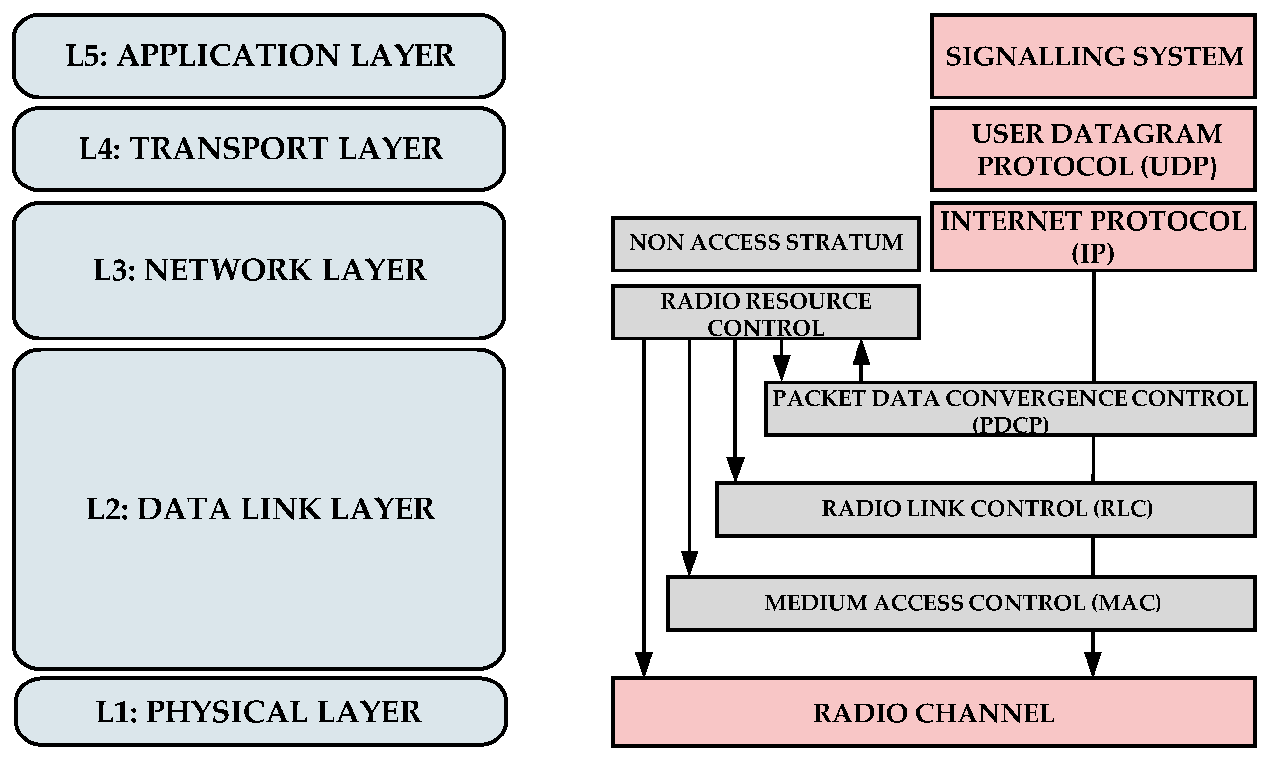
2.2. Protocol Stack Perspective

Figure 1 shows the standard protocol stack followed in this study to verify the requirements in Table 1, in which the layers marked in light red are the data to be measured in the communication between the IXL and the object controller.
In the physical layer, it is necessary to capture parameters that indicate the quality of communication at the radio level to see the correlation with the data in the network and application layers. The parameters for the analysis are RSRP, RSRQ and SINR.
In the network layer, the latency and jitter are the essential parameters [12] since they determine the successful communication rhythm required by the application layer. In the signalling systems, some timeouts are defined to acknowledge the updated and recent information about the progress of the railway operation. This means that if the communication system is not fast enough, the railway application information may be overdue at the application layer, implying a problem in the system’s availability.

3. Measurement Set-Up and Prototype

This section presents the prototype hardware architecture, the software developed, and the measurement set-up proposed in this study.

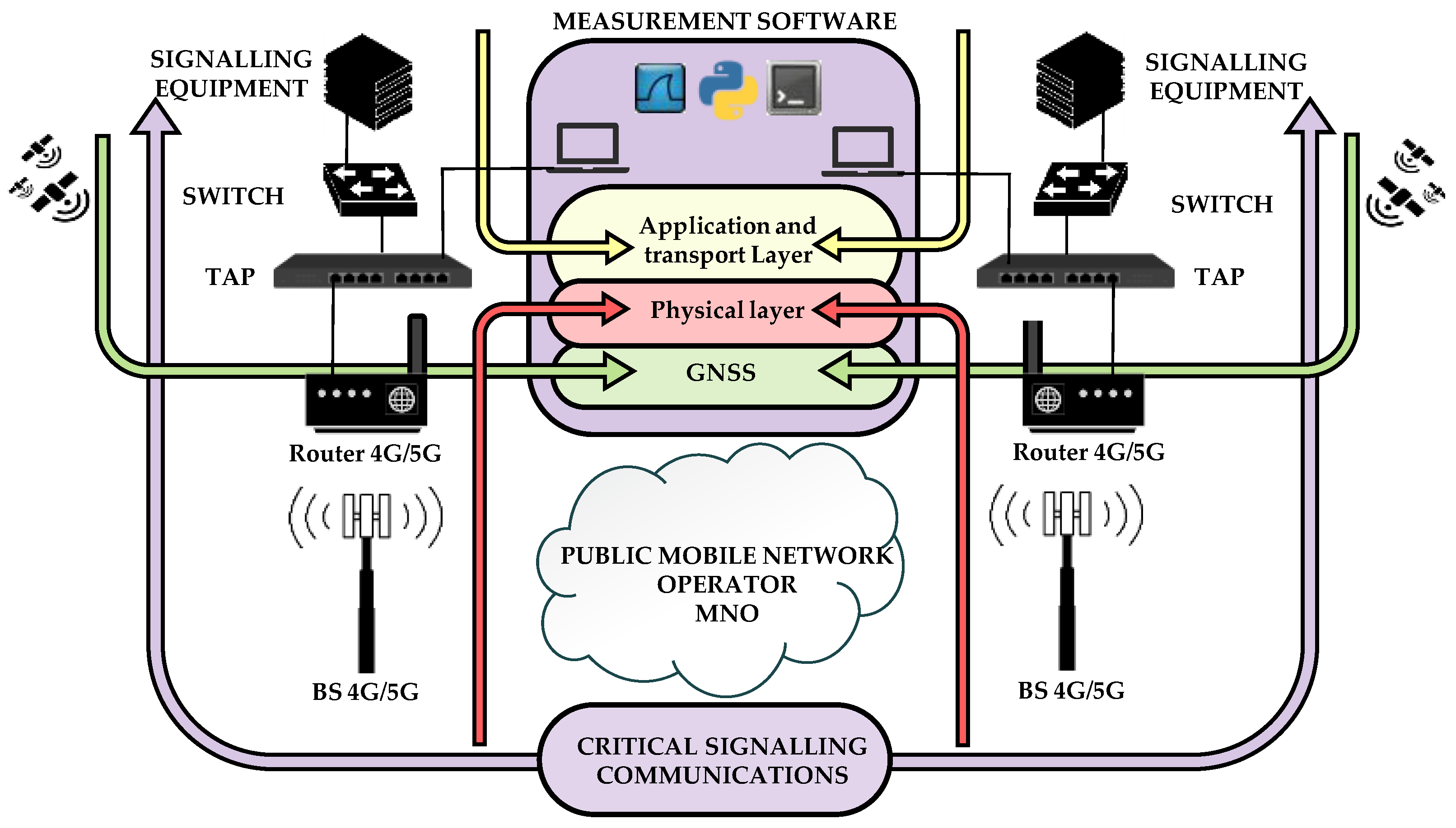
3.1. Prototype Architecture

In this area of research for the railway sector, the interests of the companies have just begun to appear. Hence, no commercial tools are available to measure and analyse the overall behaviour of signalling systems using 4G/5G mobile networks. In this study, the goal is mainly to measure the traffic generated between an IXL and an object controller with enough detail to define the radio and network parameters required to provide reliable service to signalling systems. For this reason, this study presents a prototype developed for this purpose, which measures and processes the KPIs from the protocol-stack perspective.
Figure 2 shows the architecture schema of the prototype and the elements to which it is connected. Following Figure 1, the lower layer represents the MNO network; the upper part represents the signalling equipment as the application layer; and, in the middle, the prototype connects to the MNO and the signalling equipment as an alternative to the fibre optical network acting as the physical and network layer.
The signalling equipment comprises a real object controller and an IXL simulator. Both connect to two E-Lins H900fq-W-G devices, which include 4G/5G modem and routing capabilities. To these components, non-invasive measurement elements are connected based on traffic sniffers and signal meters developed for this purpose.
The MNO network type considered in these study scenarios has been the following:
  • Prototype based on commercial equipment as a regular user.
  • Prototype based on enterprise solutions with an SLA [13] that guarantees, among other parameters, a maximum latency of 80 ms, a packet loss of 0.2% and a monthly availability of 99.5%.

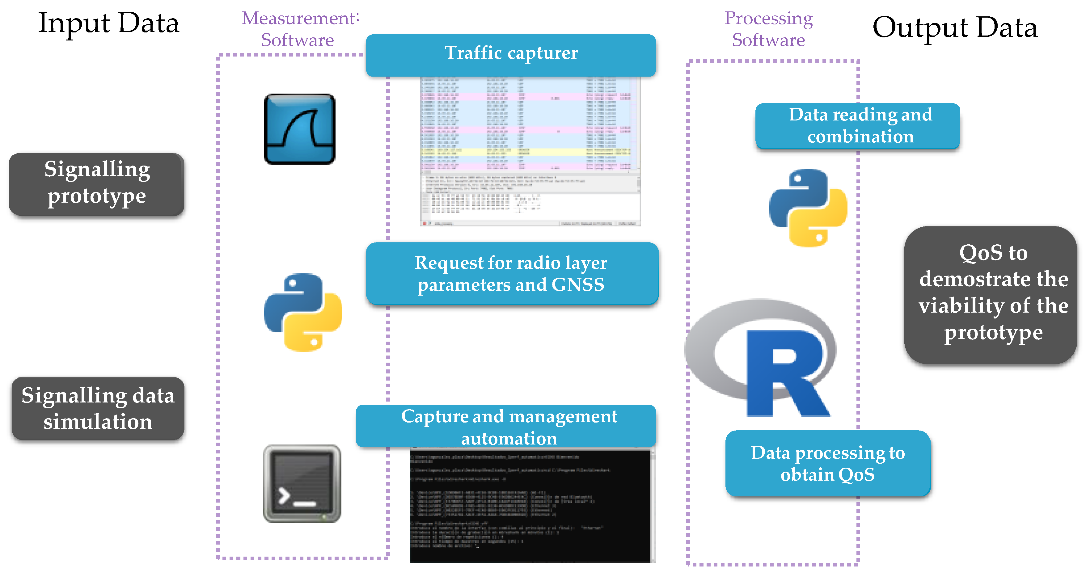
3.2. Software Scheme

The software scheme is shown in Figure 3, where the different functions are distributed in modules supported by a set of technologies. This software allows the capture, collection and post-processing of the signals at the physical, network and application levels.
The functions of the software are defined as follows:
  • Measurement software: This section is divided into three modules whose purpose is to request network parameters, and capture and save them.
    -
    Radio and GNSS parameter request module: Developed in Python. It is responsible for requesting, in 1-second intervals, the radio and mobile communication parameters and GNSS parameters, such as speed and geographical coordinates.
    -
    Data capture module: using Wireshark. The wired interface captures the network, transport and application data, whereas the Wifi interface captures the radio and GNSS data.
    -
    Measurement software control module: Developed in ’.cmd’ batch programming, it is responsible for synchronising the two previous modules and saving the data.
  • Processing software: Divided into two modules whose purpose is to transform the data and check the quality of the network for signalling services.
    -
    Data processing module: Developed in Python, it is responsible for transforming the files and filtering the resulting files from the measurement software (‘.pcapng’) to others ready for analysis.
    -
    Analysis module: Developed in R, it is responsible for visualising the data and generating statistics to qualify the communication.

3.3. Scenarios

This section presents the different scenarios in which the study has been carried out to completely characterise the communication behaviour of the proposed system from the protocol–stack perspective to then reproduce this characterisation in a realistic railway environment.

3.3.1. Railway Laboratory Tests

The tests use a mock-up of a real object controller and an IXL simulator. The results show the correlation between the application layer (signalling response time and data rate) and network parameters (bit rate, latency and jitter) according to the signalling system requirements defined in Table 1.

3.3.2. Telecommunications Laboratory Tests

The tests compare the LTE radio network and Non-Standalone (NSA) 5G. The objective is to analyse how the system works in an area with 5G deployment, demonstrating its improvement compared to 4G networks. Likewise, this scenario allows a comparison between SLA and regular users.
Long-term measurements have been carried out, specifically 672 periods of 15 min. The collected data allows the correlations between the radio parameters and the latency to be found according to the signalling communication requirements based on UDP.

3.3.3. Field Railway Tests

The objective of the field tests is to analyse the performance of the proposed system in a realistic railway line.
This test is performed in the railway environment in a low railway density traffic line. The selected location presents a low coverage area, which provides the most restricting option to prove this proposed implementation. This location is between Guardo (Plasencia, Spain) and Mataporquera (Cantabria, Spain).
The Guardo–Mataporquera railway section is a non-electrified single track in the north of Spain with no communication infrastructure deployed nowadays. It follows a route 65 km long, including two main stations (Guardo and Mataporquera stations) and two secondary stations (Santibañez de la Peña and Vado-Cervera stations).

4. Results

This section describes the results obtained in the tests carried out in the different scenarios presented in Section 3.3. The analysis focuses on the characterisation of critical signalling traffic to later analyse the behaviour of this traffic in a telecommunications laboratory environment. Finally, field measurements evaluate the behaviour in a real environment of low-density railway traffic.

4.1. Signalling Data Traffic Characterisation

This section presents the critical data characterisation for the signalling system.

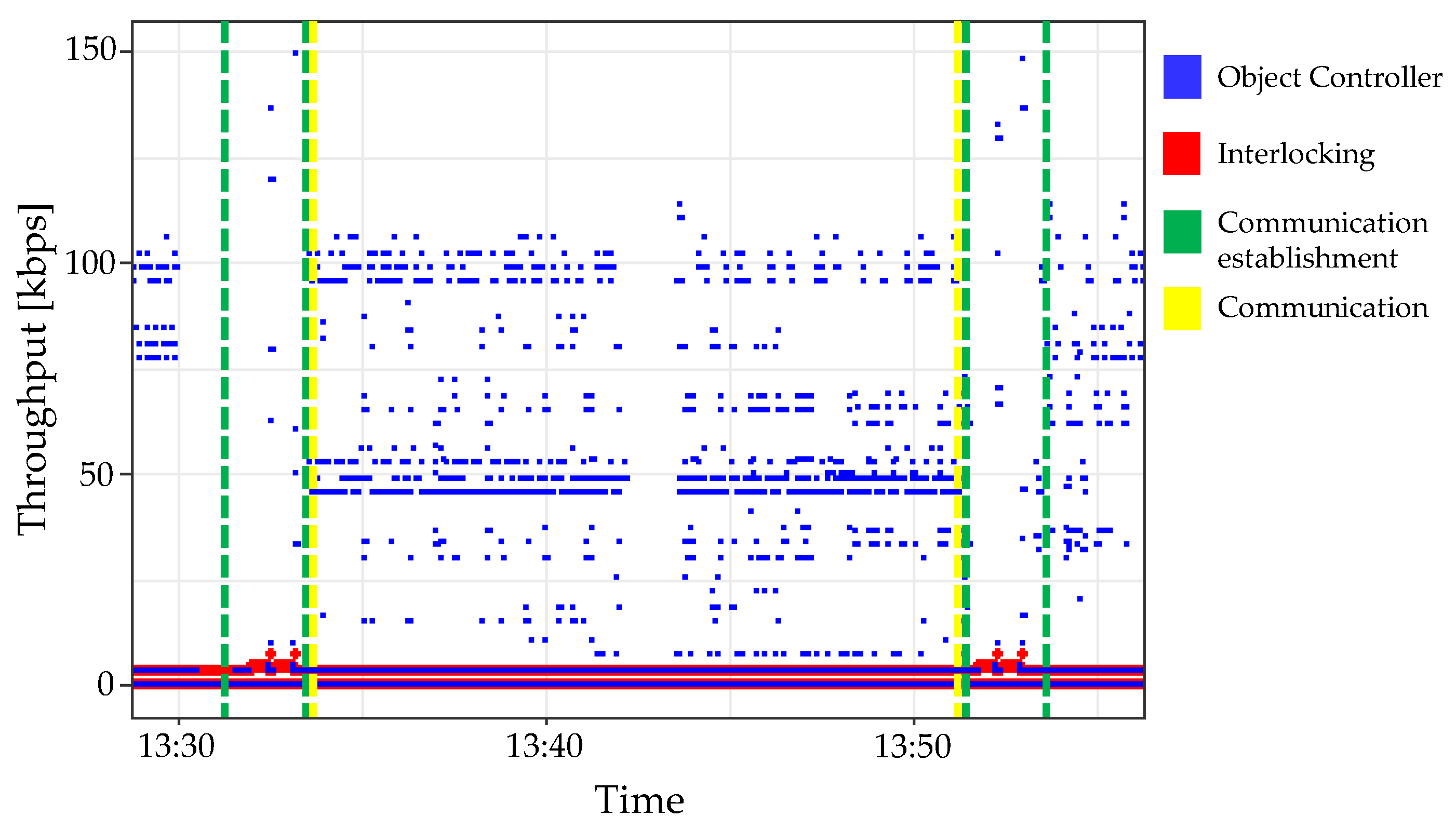
4.1.1. Bit Rate Characterisation

Figure 4 shows the bit rate transmitted when the signalling equipment performs the following process:
  • Communication establishment: process to establish the communication at the application layer marked between the green vertical lines.
  • Signalling tasks marked between the yellow vertical lines:
    -
    Point supervision: periodic task to supervise the state of the point machine;
    -
    Trailing: detection of a point between trailers when the train passes.
  • Communication failure: communication establishment and progress not performed successfully at the application level while having connected the communication system correctly.
The results show that the bit rate varies according to the performed task. They include measurements with signal levels ranging between −75 and −117 dBm on LTE at 1800 MHz. The overall traffic is around 3.8 kbps, as summarised in Table 2, where the specific amount of data is described according to the signalling equipment involved. There are peaks of 150 kbps when communication is established. Moreover, communication disconnections cause the duplication of the throughput when radio conditions are degraded.

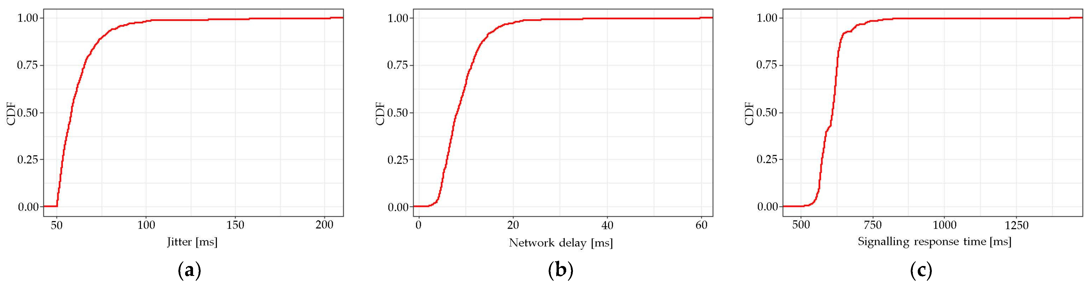
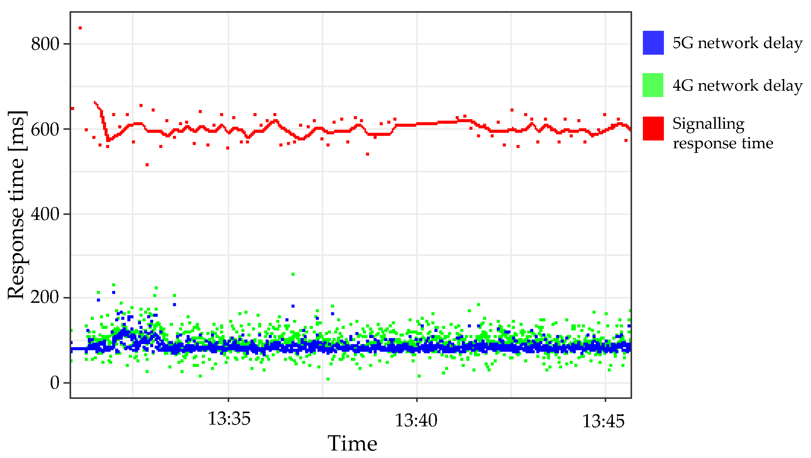
4.1.2. Latency and Jitter

Latency measurements indicate an average message transfer delay of 610 ms, in which 70 ms is dedicated to the network delay (see Figure 5). This means that the prototype provides a reduced network latency of 66.1% compared to the complete communications establishment. Moreover, as Figure 6b shows, the network can provide a delay lower than 150 ms 99% of the time. As a result, the overall signalling response time is lower than 800 ms 99% of the time, as shown in Figure 6c.
In terms of jitter, the signalling system sends information every 318 ms (communication heartbeat) in UDP. For this reason, if the network jitter exceeds this value, the packets received by the signalling equipment will be out of order, which could cause impairment or even failure in the communication process due to UDP not providing congestion control or reception confirmation. In this case, it has been found that the prototype offers a jitter of less than 40 ms in 99% of cases, which indicates that the packet reception variation margin may still be 86.7% higher than measured, as Figure 6a describes.
In short, the most restrictive network parameter for establishing communications is latency since the signalling equipment requires a message transfer period lower than 1.8 s in a round-trip measurement, as described in Table 1.

4.2. Telecommunication Tests

During these tests, the objective is to assess the different behaviour according to the MNOs’ services provision. Along this section, the measurements are performed simulating signalling critical data according to Section 4.1.

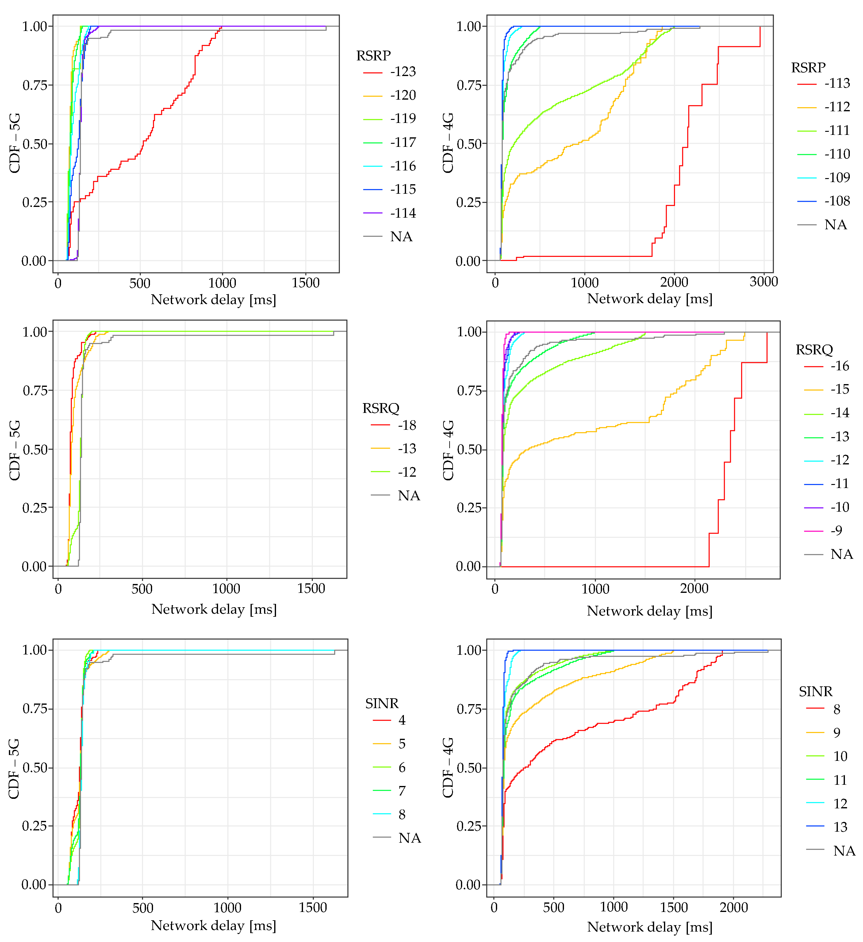
4.2.1. 4G and 5G Characterisation

Figure 7 shows the comparison between 4G and 5G networks at physical and network layers. It describes the cumulative density function of each measured value for RSRP, RSRQ and SINR according to the network latency. This result makes it possible to determine the KPIs to guarantee the proper working of the critical services considering the signalling data characterisation. These KPIs are summarised in Table 3, including the latency obtained 99% of the measured time.
Considering the KPIs in Table 1, the maximum network round-trip time is set to a threshold of 500 ms (50% margin over the maximum gap measured of 1 s). Figure 7 shows that the RSRP shall be greater than −109 dBm for a 4G network, whereas the NSA of 5G allows a decrease down to −120 dBm.
Moreover, it is also clear how the system is more stable as the signal levels increase. In terms of availability, an RSRP of −108 dBm provides a latency lower than 200 ms 99% of the time versus −109 dBm, which guarantees a threshold of 300 ms.
Following similar reasoning, RSRQ and SINR can go down to −12 and 10 dB, respectively, for 4G networks. Although in the 5G NSA network, no minimal values have been found for these KPIs, the SINR of 4 dB provides adequate performance of the transmission data, and RSRQ can provide satisfactory quality service with −13 dB. This result shows a significant improvement in comparison to 4G networks.
This study shows the minimal values to obtain sufficient signal levels to provide the required network parameters. However, in a process design, more restrictive values should be selected in order to increase the probability of fulfilling the requirements more often.

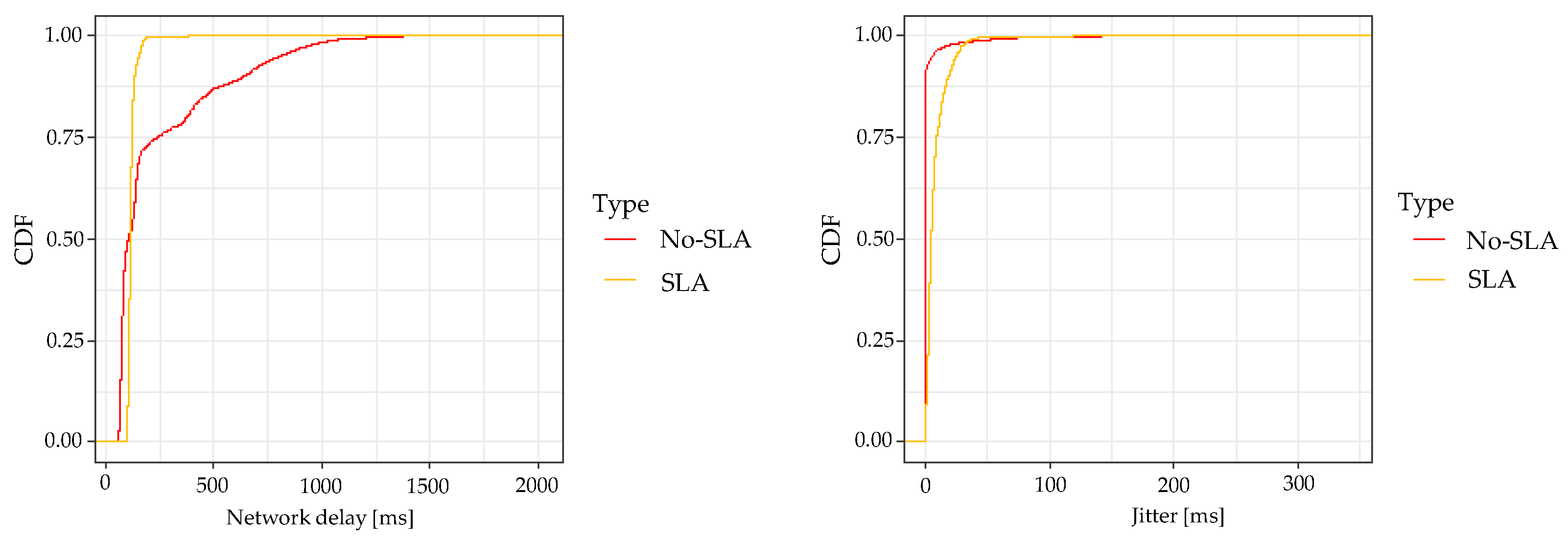
4.2.2. Comparison between a Regular User and Enterprise Solution with SLA

Figure 8 shows the latency considering an MNO contract with SLA and as a regular user.
The results show similar average latency along the network. However, there is substantially more stability for the SLA case. This is because the SLA grants priority over the network. Therefore, as the figure shows, its availability increases in latency. In contrast, the jitter results are very similar both cases.

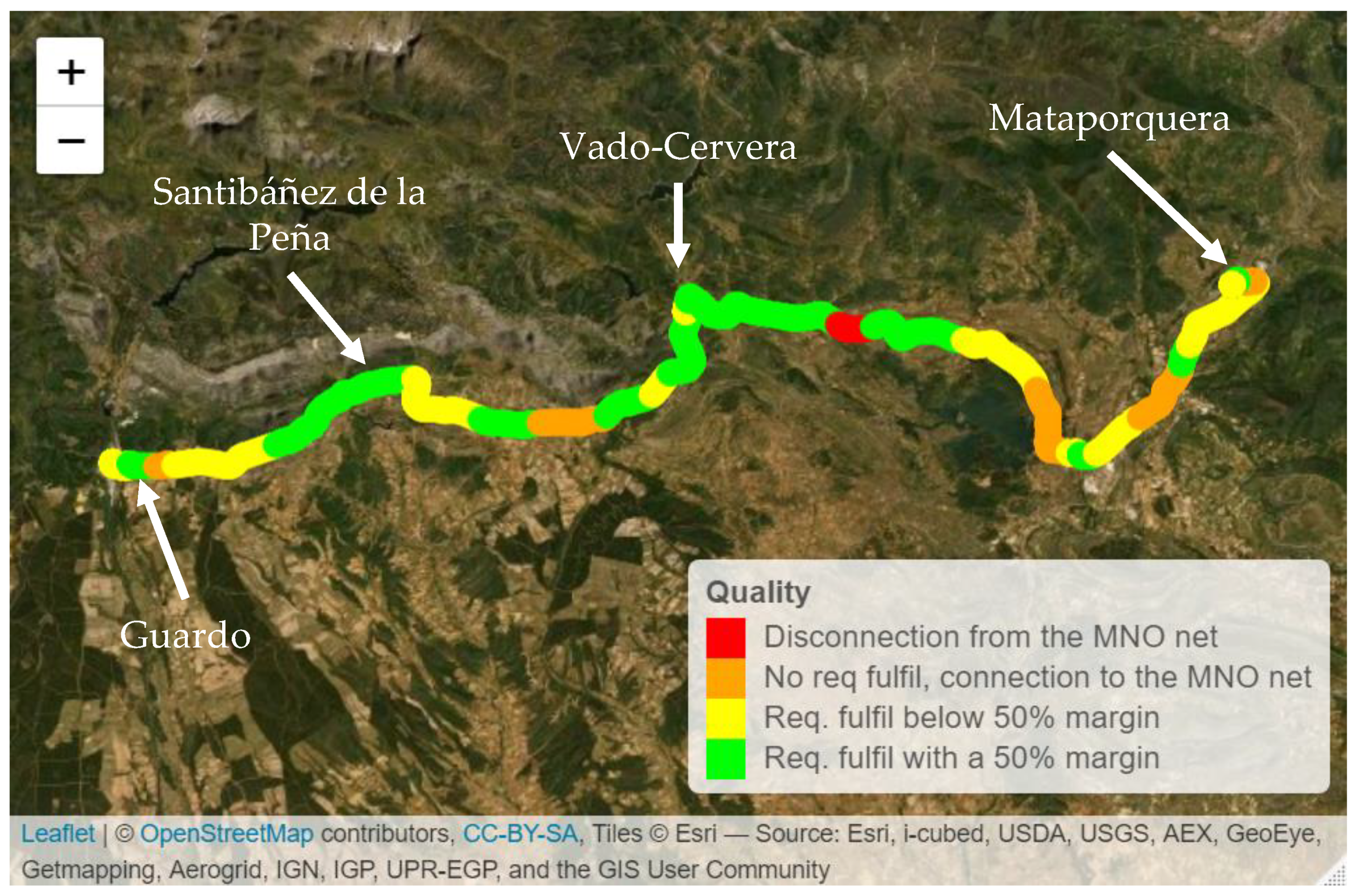
4.3. Field Measurements

Figure 9 shows the KPI test along the Guardo–Mataporquera section according to the network and radio KPIs shown in Table 2 and Table 3, respectively. The green and orange colours show the areas where all these KPIs are fulfilled. The former includes locations with a margin greater than 50% of the requirements, whereas the latter does not necessarily provide this margin. In the figure, the yellow colour shows the locations where the connection to the MNO is alive (see Table 3 KPIs) with any network parameters not fulfilled (degraded condition case). Finally, the red areas show no connection at all to the MNOs.
These measurements only show LTE developments since, in the selected area, there is no 5G deployment at the moment. This is the case with most of the low railway density traffic currently, showing more realistic results. Moreover, as shown in Section 4.2.1, the worst-case scenario is for 4G networks, as 5G allows more restrictive radio parameters.
The results show a good performance along the whole line except for a short area in a remote area. Focusing on the stations, the KPIs’ success rate increases to be included in the green areas for the four stations. This means that these field measures validate the hypothesis of implementing the proposed solution along this railway line as they fulfil the network and radio KPIs, presenting a 50% additional performance of all these parameters at the stations. Moreover, it is also a relevant result that the MNO covers most of the railway section.

5. Conclusions

Signalling communications have been established through public telecommunications networks via MNOs for railway signalling critical data using 4G and 5G networks. The results demonstrate that the hypothesis is fulfilled since communications between signalling devices based on the prototype can provide the quality of service required in terms of the physical and network layers. The study shows a characterisation of 4G and 5G radio networks, obtaining a non-linear correlation between the signal level parameters and the latency offered by the MNO mobile network. At the KPI level, this study shows how the prototype provides a maximum of 150 ms 99% of the time for low radio values of −109 dBm in 4G and −120 dBm in 5G networks, considering the 500 ms latency threshold allowed for this service. At the system level, it is observed that this system can be extended to the whole signalling system (field elements-IXL, OCC-IXL, among others).

Author Contributions

Conceptualization, A.G.-P. and R.G.C.; Data curation, R.B.A.B.; Funding acquisition, R.G.C.; Investigation, A.G.-P. and R.B.A.B.; Project administration, A.G.-P. and R.G.C.; Software, R.B.A.B.; Supervision, C.B.R.; Validation, C.B.R.; Writing—review & editing, A.G.-P. All authors have read and agreed to the published version of the manuscript.

Funding

This research was funded by Ineco thanks to its Innovation Department under the scope of the 5siG innovation project carried out during the years 2020–2021.

Institutional Review Board Statement

Not applicable.

Informed Consent Statement

Informed consent was obtained from all subjects involved in the study.

Data Availability Statement

Data presented is original and not inappropriately selected, manipulated, enhanced, or fabricated.

Acknowledgments

The authors would like to thank Thales for the collaboration in the project grating the railway signalling equipment from the Thales laboratory and Adif for allowing these measurements along Guardo–Balmaseda Railway Line. This study is aligned with the plan of deletion of Telephonic Block along approximately 3000 km along the Spanish railway lines.

Conflicts of Interest

The authors declare that there are no conflict of interest regarding the publication of this paper.

Abbreviations

The following abbreviations are used in this manuscript:
4GFourth-generation mobile communications
5GFifth-generation mobile communications
CCTVClosed Circuit Television
CDFCumulative Distribution Function
dBDecibel
dBmDecibel-milliwatts
DLDownlink
FRMCSFuture Railway Mobile Communication System
GNSSGlobal Navigation Satellite System
GSM-RGlobal System for Mobile communications - Railway
IoTInternet of Things
IPInternet Protocol
ITSIntelligent Transport Systems
IXLInterlocking
kbpsKilobits per second
KPIKey Performance Indicator
LTELong Term Evolution
MACMedium Access Network
MCPTTMission Critical Push-To-Talk
MNOMobile Network Operator
MTCMachine Type Communications
msMilliseconds
NSANon-Standalone
ObjCObject Controller
OCCOperation Control Center
OFDMOrthogonal Frequency Division Multiplexing
PDCPPacket Data Convergence Control
RLCRadio Link Control
RSRPReference Signal Received Power
RSRQReference Signal Received Quality
SINRSignal to Interference plus Noise Ratio
SLAService Level Agreement
TAPTerminal Access Point
UDPUser Datagram Protocol
ULUplink

References

  1. Berbineau, M.; Behaegel, R.; Garcia-Loygorri, J.M.; Torrego, R.; D’Errico, R.; Sabra, A.; Yan, Y.; Soler, J. Channel Models for Performance Evaluation of Wireless Systems in Railway Environments. IEEE Access 2021, 9, 45903–45918. [Google Scholar] [CrossRef]
  2. Zhong, G.; Xiong, K.; Zhong, Z.; Ai, B. Internet of things for high-speed railways. Intell. Converg. Netw. 2021, 2, 115–132. [Google Scholar] [CrossRef]
  3. Mullner, R.; Ball, C.F.; Ivanov, K.; Treml, F.; Spring, G. Quality of service in GPRS/EDGE mobile radio networks. In Proceedings of the 2004 IEEE 59th Vehicular Technology Conference, Milan, Italy, 17–19 May 2004; Volume 5, pp. 2507–2511. [Google Scholar]
  4. González-Plaza, A.; Calvo-Ramírez, C.; Briso-Rodríguez, C.; García-Loygorri, J.M.; Oliva, D.; Alonso, J.I. Propagation at mmW Band in Metropolitan Railway Tunnels. Wirel. Commun. Mob. Comput. 2018, 2018, 7350494. [Google Scholar] [CrossRef]
  5. Chettri, L.; Bera, R. A Comprehensive Survey on Internet of Things (IoT) Toward 5G Wireless Systems. IEEE Internet Things J. 2020, 7, 16–32. [Google Scholar] [CrossRef]
  6. Arriola, A.; Rodríguez, P.M.; Val, I.; Briso, C.; Gonzalez-Plaza, A.M.; Moreno, J.; Echeverría, E.; Goikoetxea, J. Characterization of an Outdoor-to-Indoor wireless link in metro environments at 2.6 GHz. In Proceedings of the 2017 15th International Conference on ITS Telecommunications (ITST), Warsaw, Poland, 29–31 May 2017; pp. 1–4. [Google Scholar]
  7. He, D.; Ai, B.; Guan, K.; Zhong, Z.; Hui, B.; Kim, J.; Chung, H.; Kim, I. Channel Measurement, Simulation, and Analysis for High-Speed Railway Communications in 5G Millimeter-Wave Band. IEEE Trans. Intell. Transp. Syst. 2018, 19, 3144–3158. [Google Scholar] [CrossRef]
  8. Sarfaraz, A.; Hämmäinen, H. 5G Transformation: How mobile network operators are preparing for transformation to 5G? In Proceedings of the 2017 Internet of Things Business Models, Users, and Networks, Copenhagen, Denmark, 23–24 November 2017; pp. 1–9. [Google Scholar] [CrossRef]
  9. Shah, S.P.; Pattan, B.J.; Gupta, N.; Tangudu, N.D.; Chitturi, S. Service Enabler Layer for 5G Verticals. In Proceedings of the 2020 IEEE 3rd 5G World Forum (5GWF), Bangalore, India, 10–12 September 2020; pp. 269–274. [Google Scholar]
  10. Gonzalez-Plaza, A.; Moreno, J.; Val, I.; Arriola, A.; Rodriguez, P.M.; Jimenez, F.; Briso, C. 5G communications in high speed and metropolitan railways. In Proceedings of the 2017 11th European Conference on Antennas and Propagation (EUCAP), Paris, France, 19–24 March 2017; pp. 658–660. [Google Scholar]
  11. Leles, R.D.C.D.; Rodrigues, J.J.P.C.; Woungang, I.W.; Rabel, R.A.L.; Furtado, V. Railways Networks—Challenges for IoT Underground Wireless Communications. In Proceedings of the 2018 IEEE 10th Latin-American Conference on Communications (LATINCOM), Guadalajara, Mexico, 14–16 November 2018; pp. 1–6. [Google Scholar]
  12. Du, K.X.; Carrozzo, G.; Siddiqui, M.S.; Carrasco, O.; Sayadi, B.; Lazarakis, F.; Kourtis, A.; Sterle, J.; Bruschi, R. Definition and Evaluation of Latency in 5G: A Framework Approach. In Proceedings of the 2019 IEEE 2nd 5G World Forum (5GWF), Dresden, Germany, 30 September–2 October 2019; pp. 135–140. [Google Scholar]
  13. Chounos, K.; Apostolaras, A.; Korakis, T. A Dynamic Pricing and Leasing Module for 5G Networks. In Proceedings of the 2020 IEEE 3rd 5G World Forum (5GWF), Bangalore, India, 10–12 September 2020; pp. 343–348. [Google Scholar]
Figure 1. Protocol stack design and testing approach.
Applsci 12 09003 g001
Figure 2. Prototype and measurement set-up architecture.
Applsci 12 09003 g002
Figure 3. Software-distributed modules architecture.
Applsci 12 09003 g003
Figure 4. Signalling bit rate for a set of tasks.
Applsci 12 09003 g004
Figure 5. Signalling and network round trip time.
Applsci 12 09003 g005
Figure 6. Cumulative density function of network KPIs.
Applsci 12 09003 g006
Figure 7. RSRP, RSRQ and SINR measured CDF for 4G (right) and 5G (left).
Applsci 12 09003 g007
Figure 8. MNO network performance (latency and jitter) according to SLA agreement and a regular user.
Applsci 12 09003 g008
Figure 9. Field measurements along the Guardo–Mataporquera section from Guardo–Balmaseda Railway Line.
Applsci 12 09003 g009
Table 1. Communication requirements for railway signalling equipment.
Communication Requirements for Signalling Equipment
Communication protocolUDP/IP
Message reception timeout1.8 s
Message sending period300 ms
Signalling bit rate4 kpbs
Availability>99%
Table 2. Network KPIs. Average values measured in the application layer: signalling critical services.
ParametersTheoretical ValueAverage Measured Value
Bit Rate
Overall bit rate3.8 kbpsInterlocking:
Trailing tests Trailing: 2.8 kbps
Supervision tests Supervision: 3.3 kbps
Signalling comms failure Failure: 7.5 kbps
Object Controller:
Trailing: 2.2 kbps
Supervision: 4.8 kbps
Failure: 2.5 kbps
Time
Signalling layer round trip time<1800 ms601 ms
Network delay (Latency)<500 ms70 ms
Messages period (Jitter)300 ms318 ms
Table 3. Radio KPIs. 4G/5G radio threshold values to guarantee availability 99% of the time for a latency lower than 500 ms.
LTE (4G)5G NSA
ParameterRadioLatencyRadioLatency
RSRP−109 dBm300 ms−120 dBm150 ms
RSRQ−12 dB300 msNo minimum value obtained
SINR10 dB220 msNo minimum value obtained
Publisher’s Note: MDPI stays neutral with regard to jurisdictional claims in published maps and institutional affiliations.

