


Educational Case Studies for Pilot Engineer 4.0 Programme: Monitoring and Control of Discrete-Event Systems Using OPC UA and Cloud Applications


Abstract
:1. Introduction
2. Background
3. Related Works
3.1. Urge for Education of Industry 4.0 Technologies
3.2. Training Programmes for Industry 4.0 and Education 4.0 Concept
3.3. State-of-the-Art Summary and Task Definition
4. Basic Theory
5. Research Methods
6. Educational Case Studies
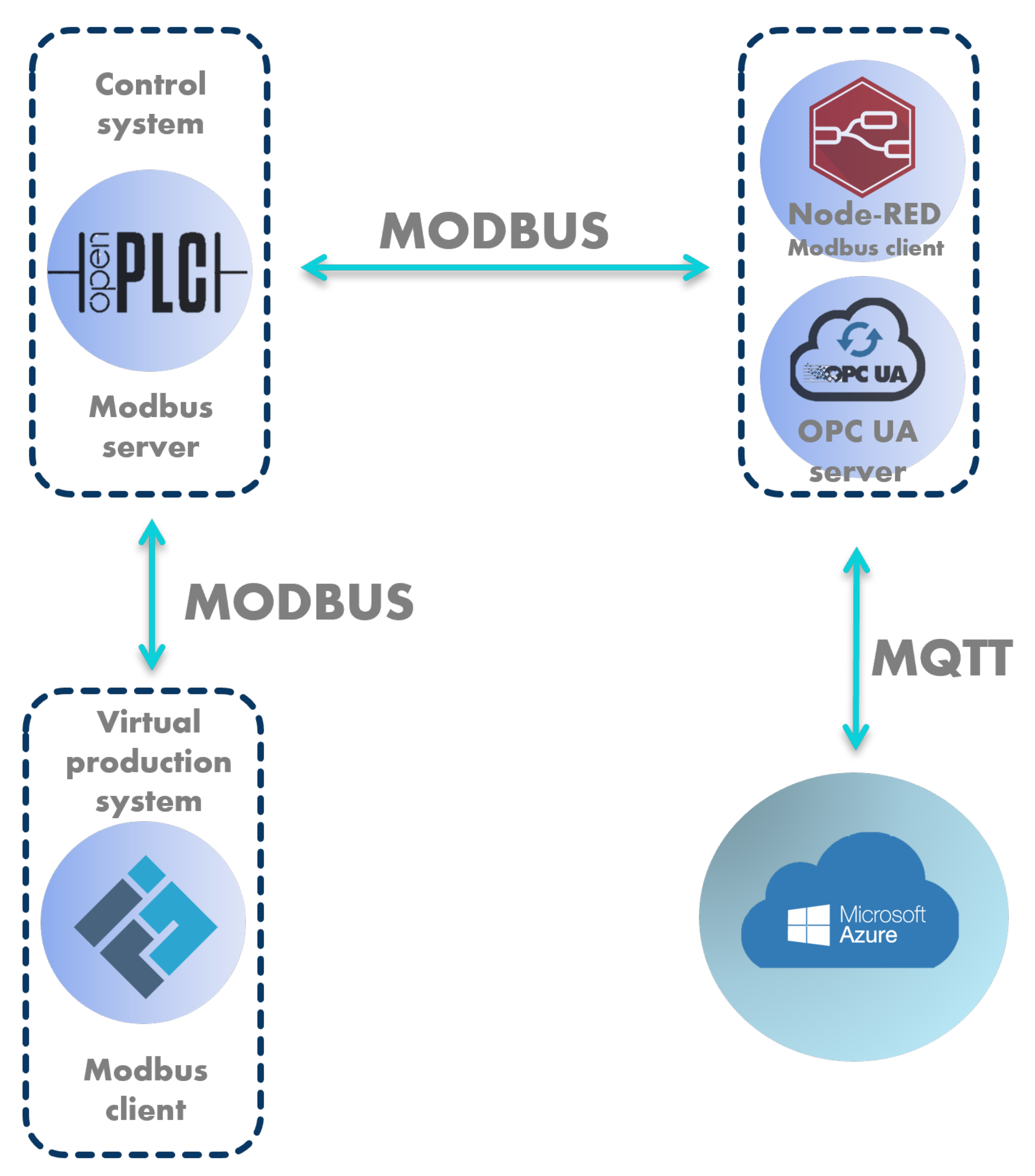
6.1. Case Study No. 1: OpenPLC Linked with Node-RED and Microsoft Azure
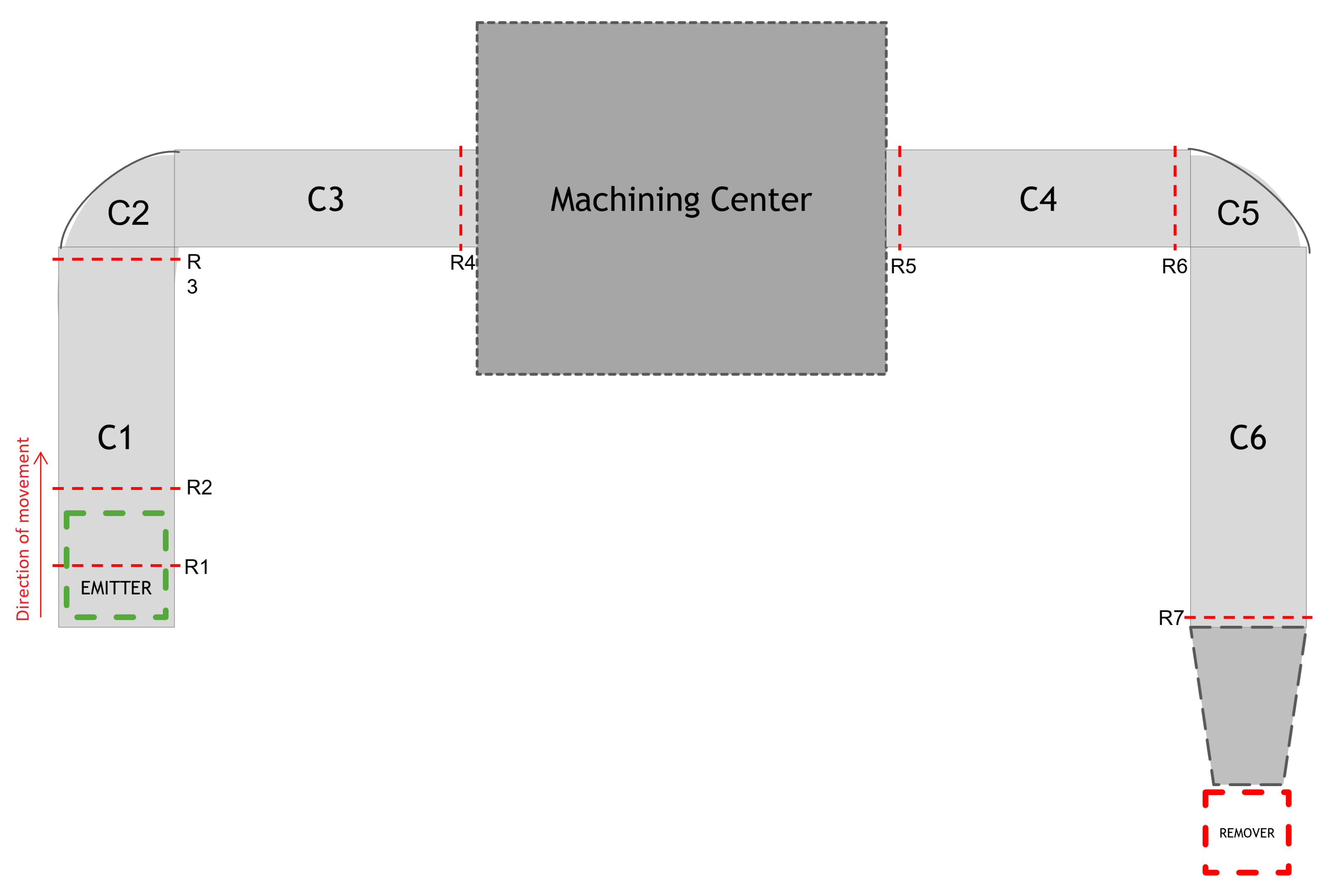
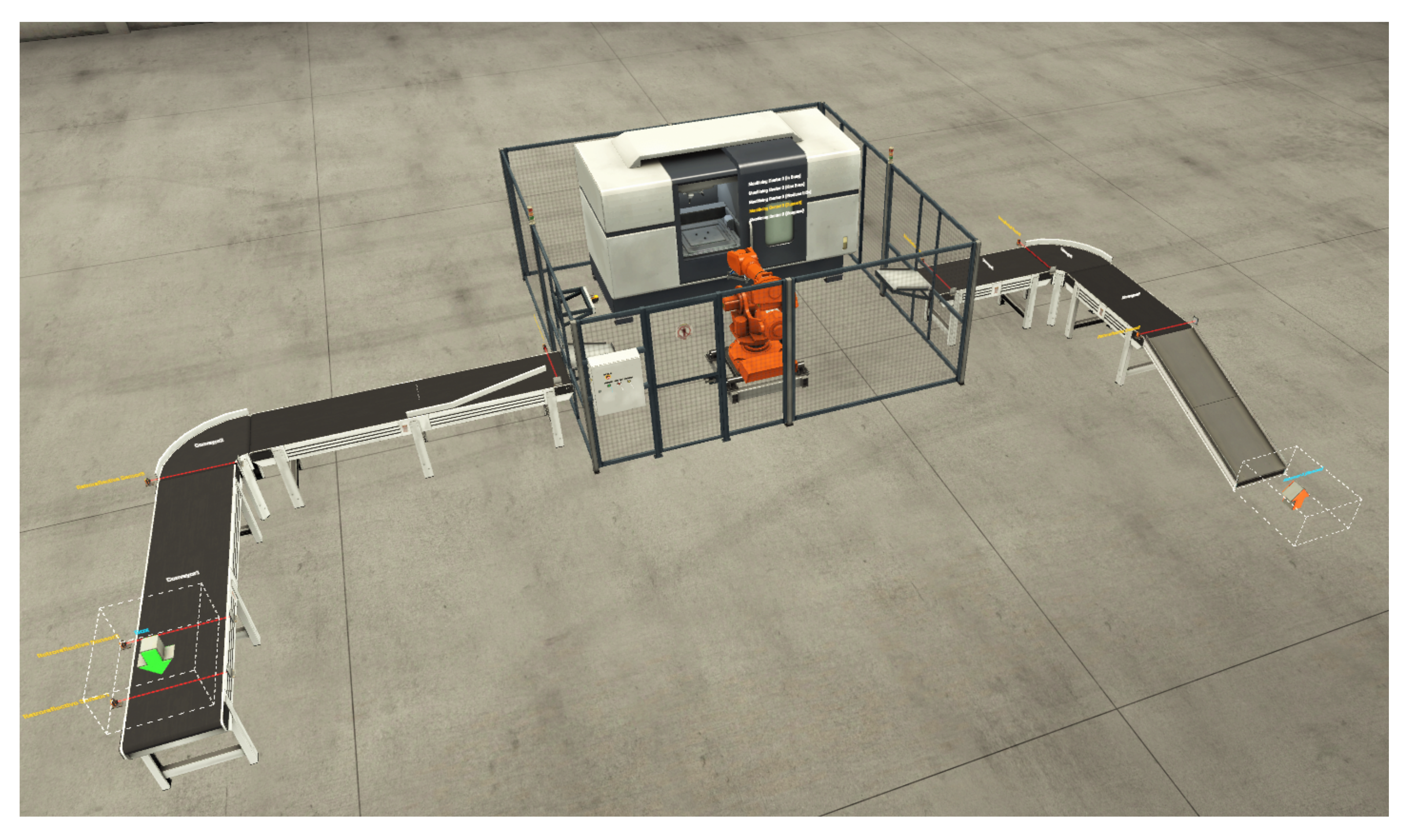
6.1.1. Discrete-Event System Specification and Behaviour
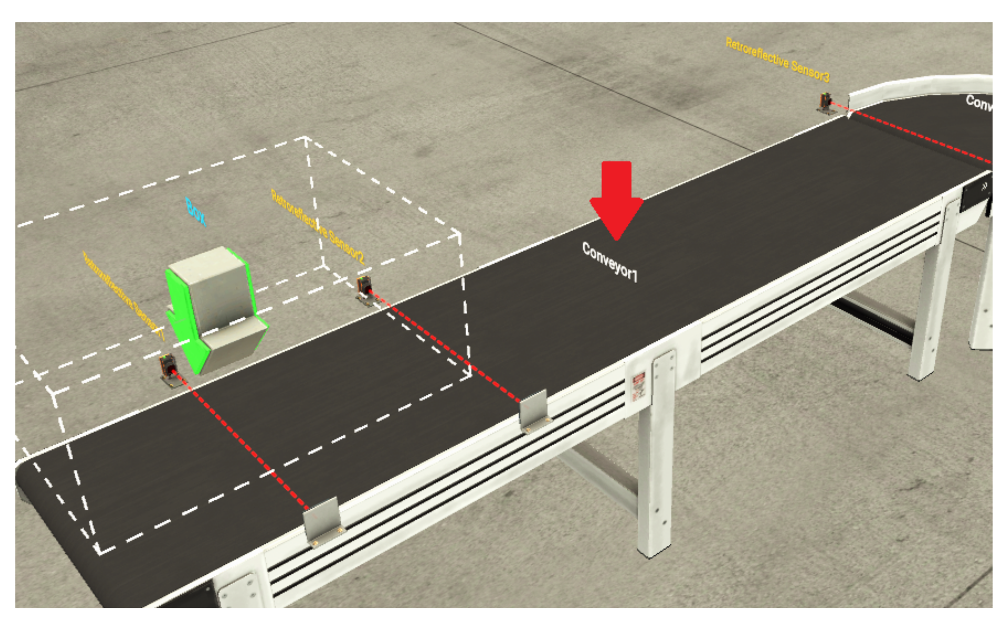
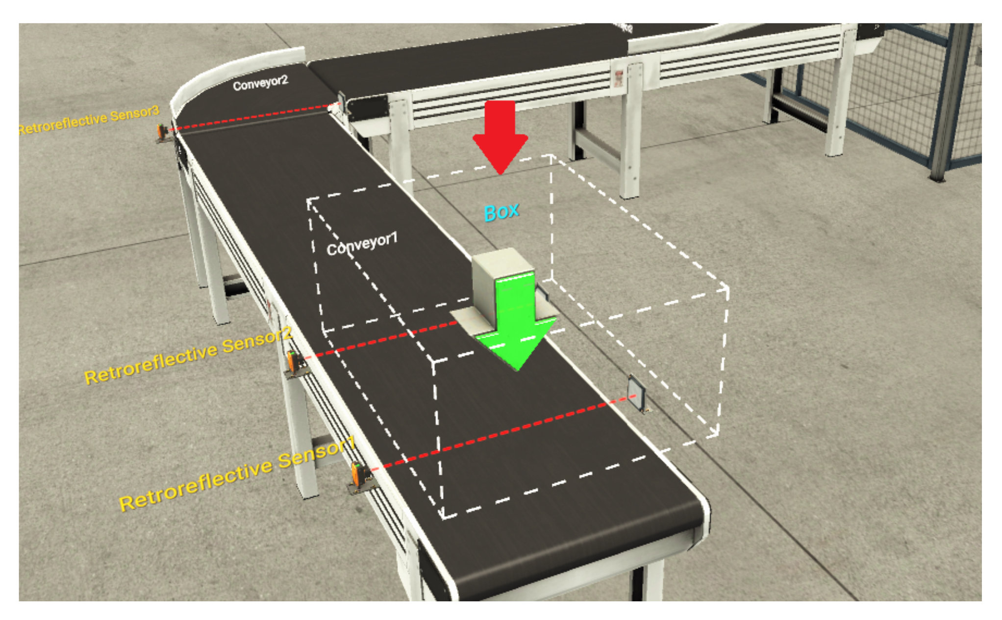
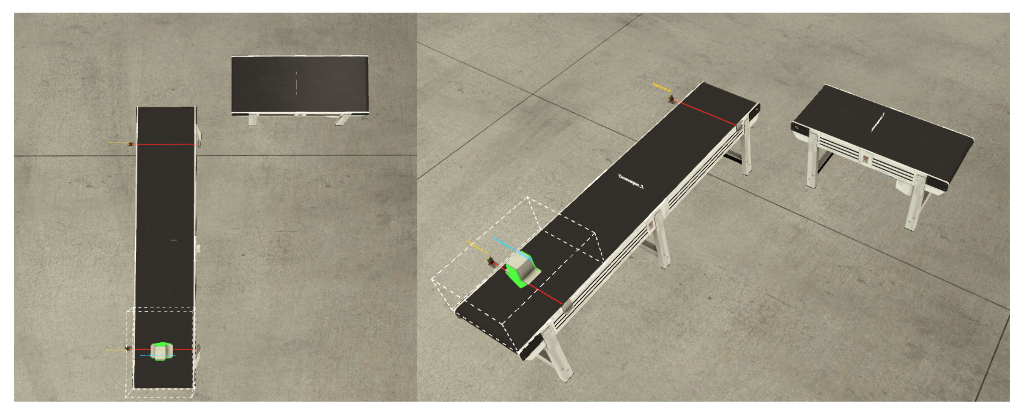
- Belt conveyor (Figure 5)—used for transporting light loads. They are available in lengths of 2, 4 and 6 m and in analogue (we can adjust the speed of the conveyor) and digital versions;
- Curved belt conveyor—used for transporting light loads and available in analogue and digital versions;
- Aligners—metal structures that are attached to the conveyor to prevent the product from falling during transport. There are four types;
- Chute conveyor—mostly used for dispatching items from conveyor belts;
- Raw Material—metal or plastic material for the manufacturing of lids or bases. In our case we understand it as a semi-finished product that needs to be machined into a finished product;
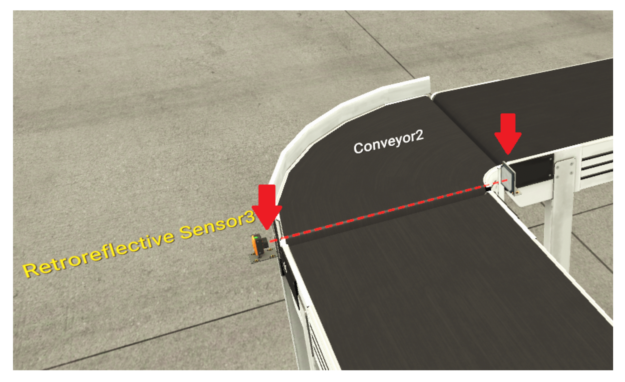
- Retroreflective Sensor and Reflector (Figure 6)—the sensor is used together with the reflector, it detects the presence of an object on the belt.
- Emitter (Figure 7)—it is the entry point of the production line, which ensures the supply of production parts/raw materials to it. Raw materials are automatically generated at time intervals according to the emitter settings.
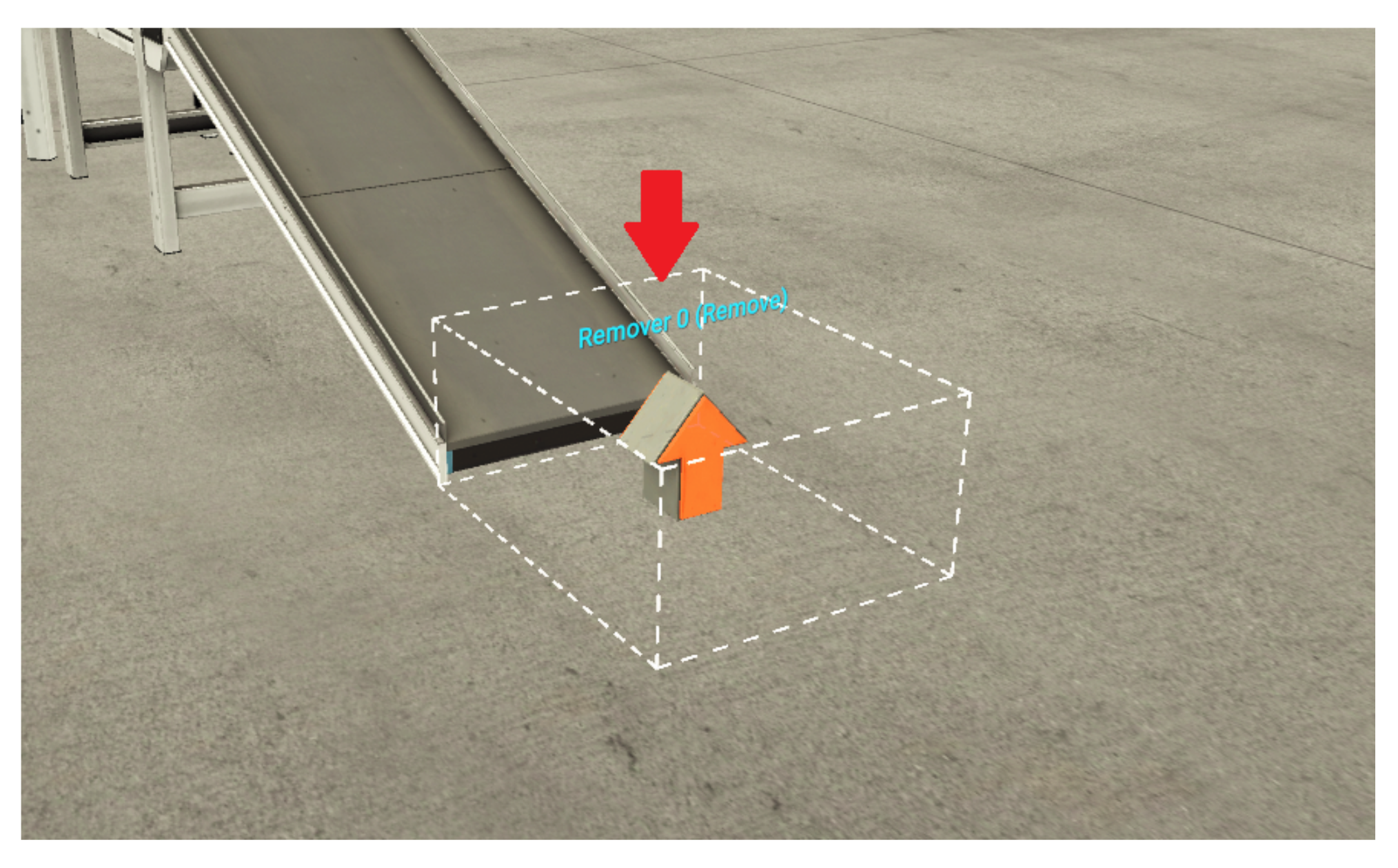
- Remover (Figure 8)—removes one or more items from the scene.
- Machining Center—a robot used for the production of pedestals.
6.1.2. Control of Discrete-Event System
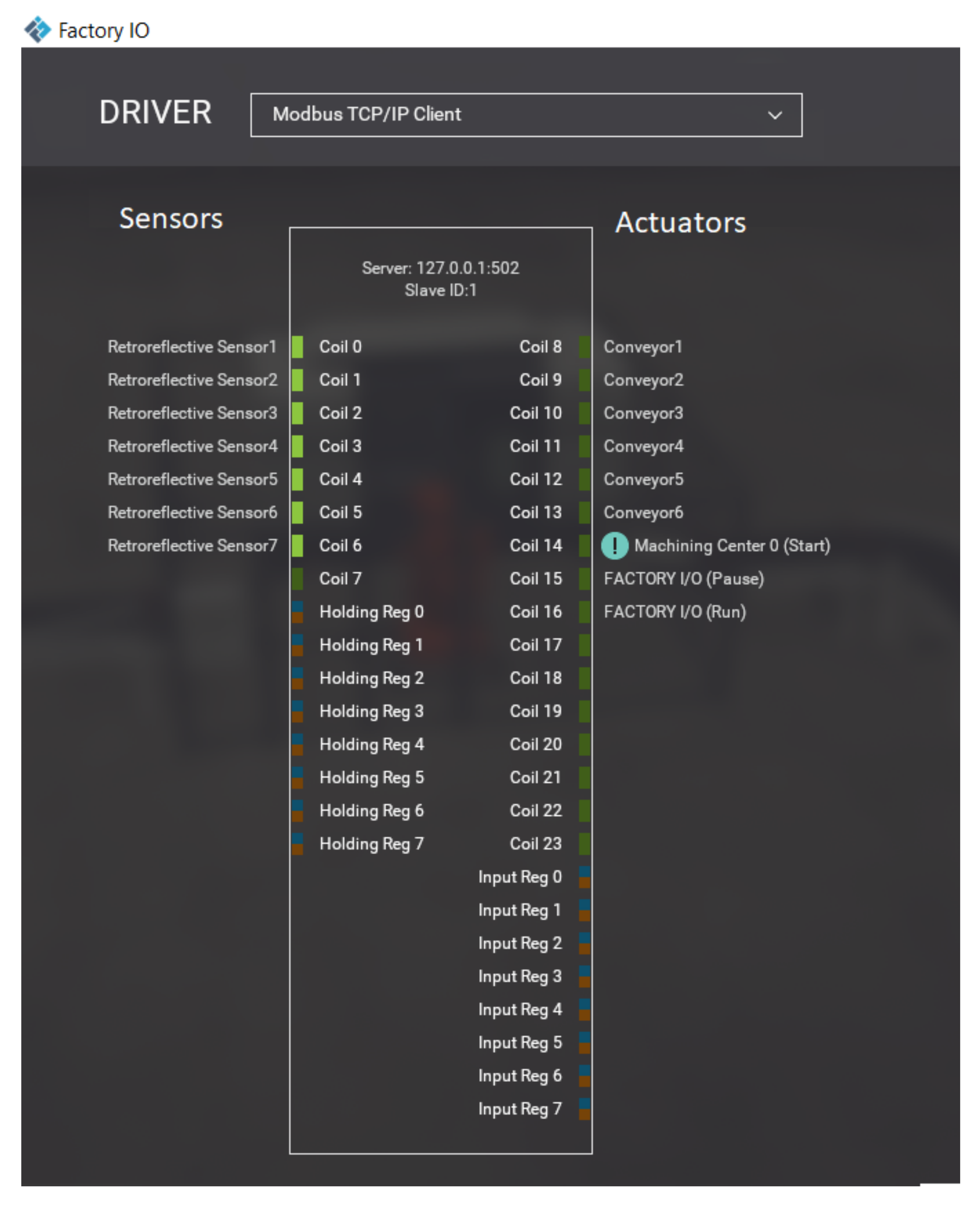
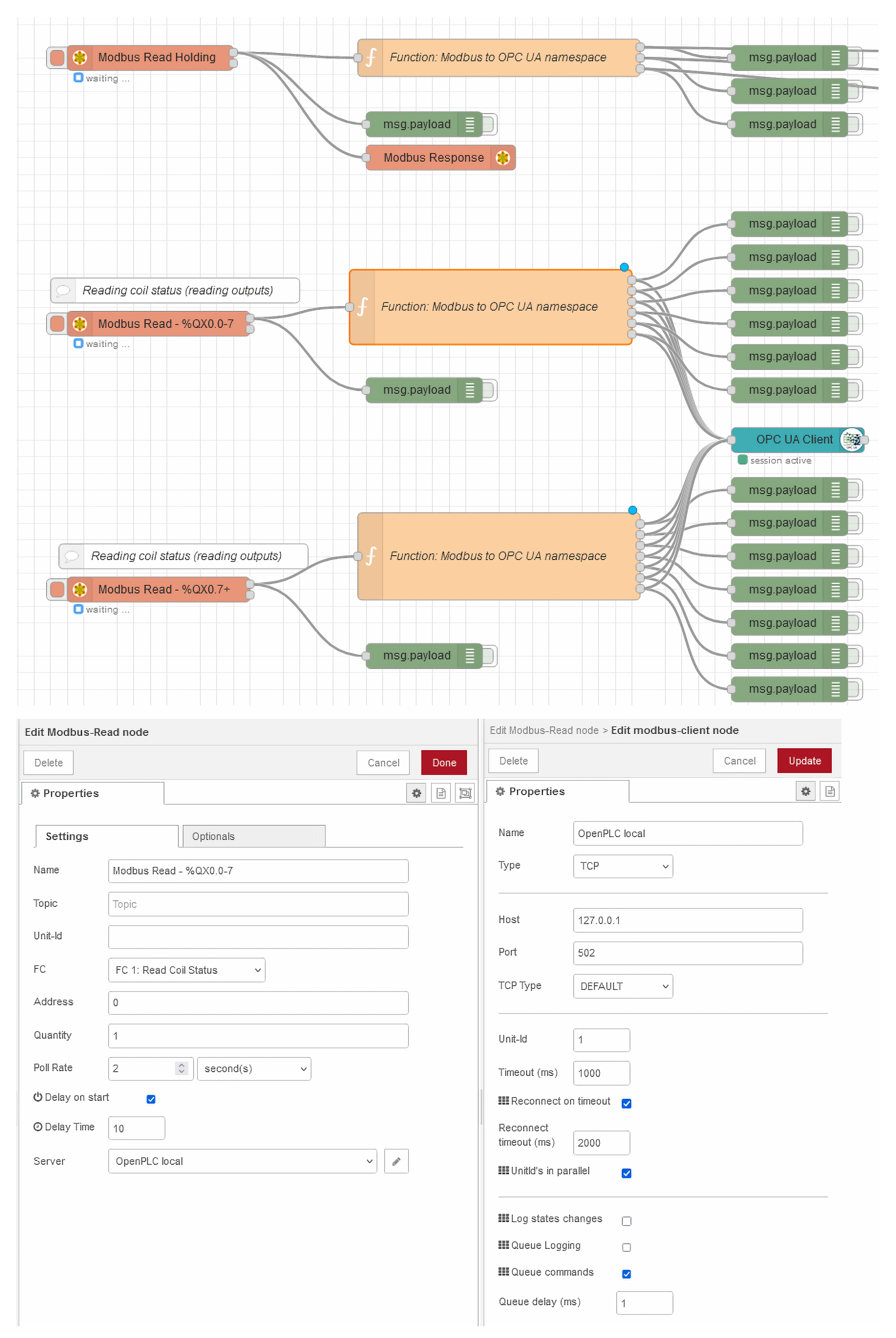
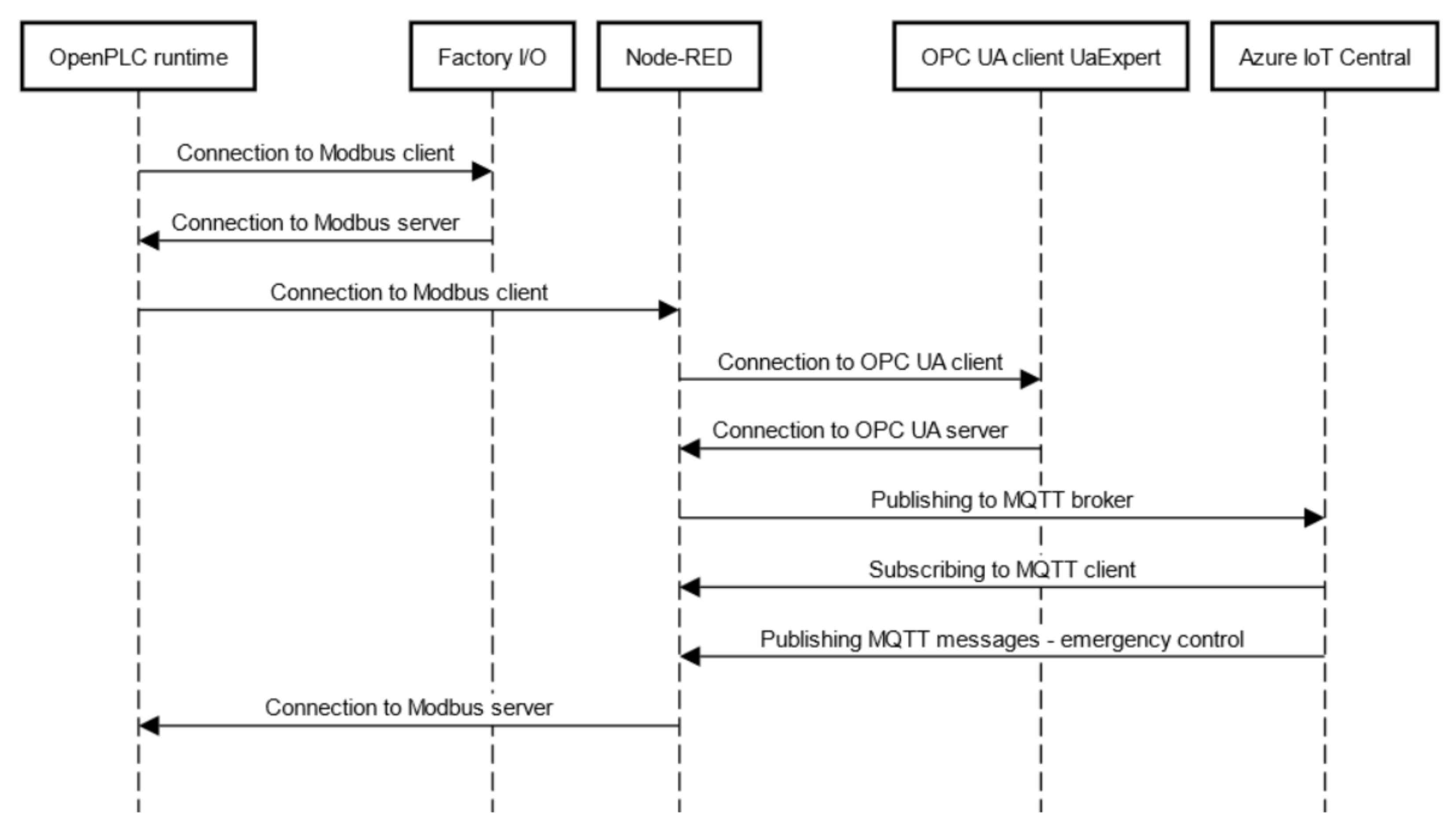
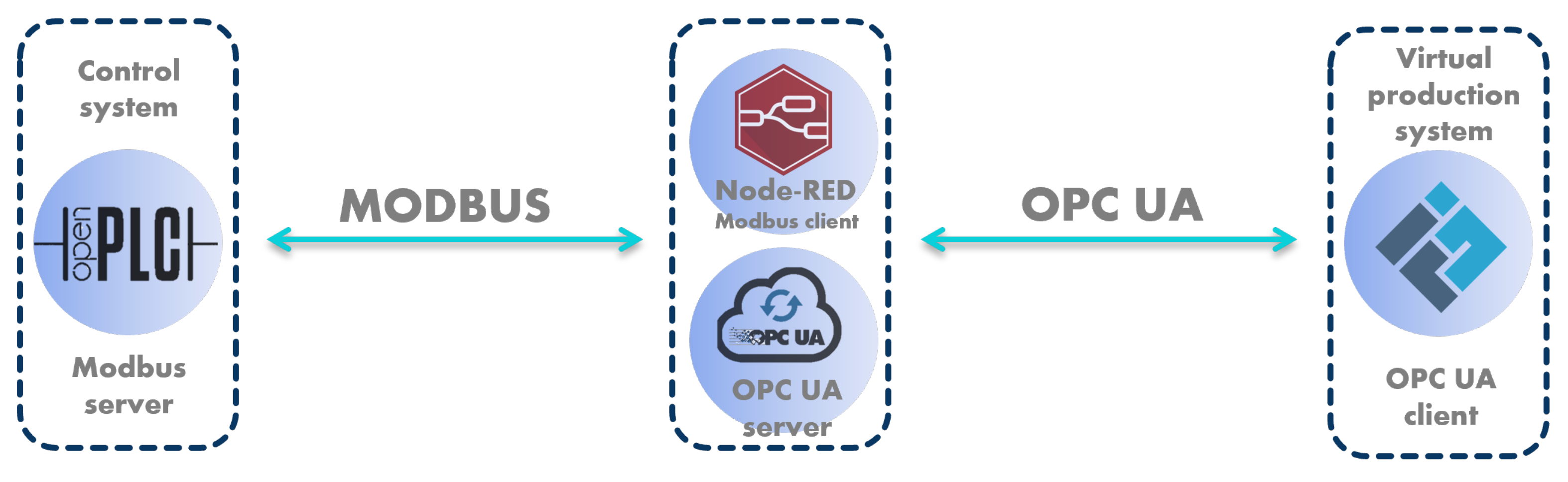
6.1.3. Communication between OpenPLC Runtime and Node-RED Middleware
- Discrete Input—A single bit (BOOL) that is used for binary input (e.g., from sensors). In our case, these are addresses of type %IX. It can only be written by the Modbus server;
- Coil—A single bit (BOOL), which is mostly used for binary output. In our case it is addresses of type %QX. It can be written not only by the server but also by the client;
- Input Register—A 16-bit read-only register. It is kind of like Discrete Input, except it is not BOOL, but it is a 16-bit INT that can be unsigned or signed;
- Holding Register—A 16-bit register designed for both read and write. It is kind of like Coil, except it is not a BOOL, but it is a 16-bit INT that can be unsigned or signed.
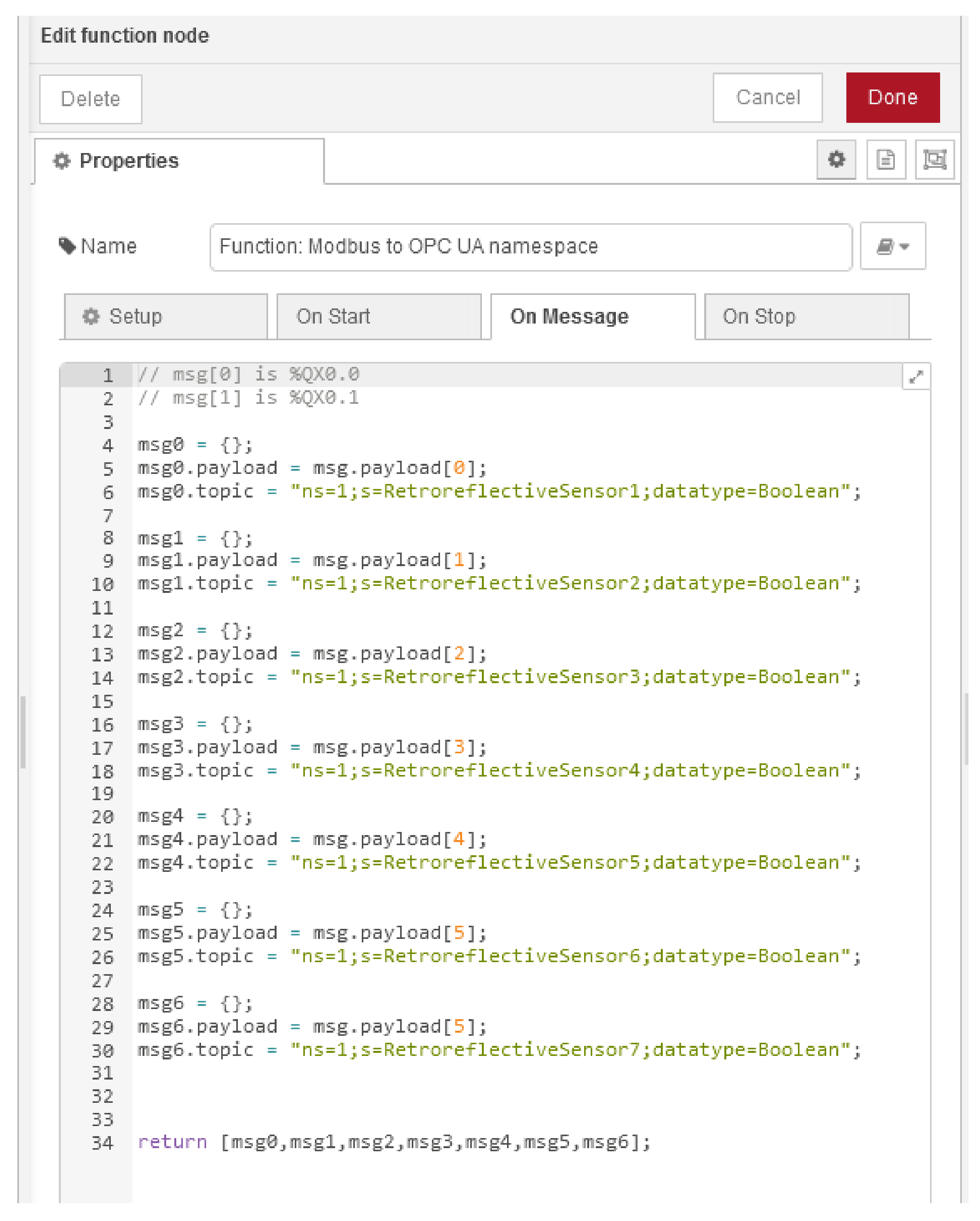
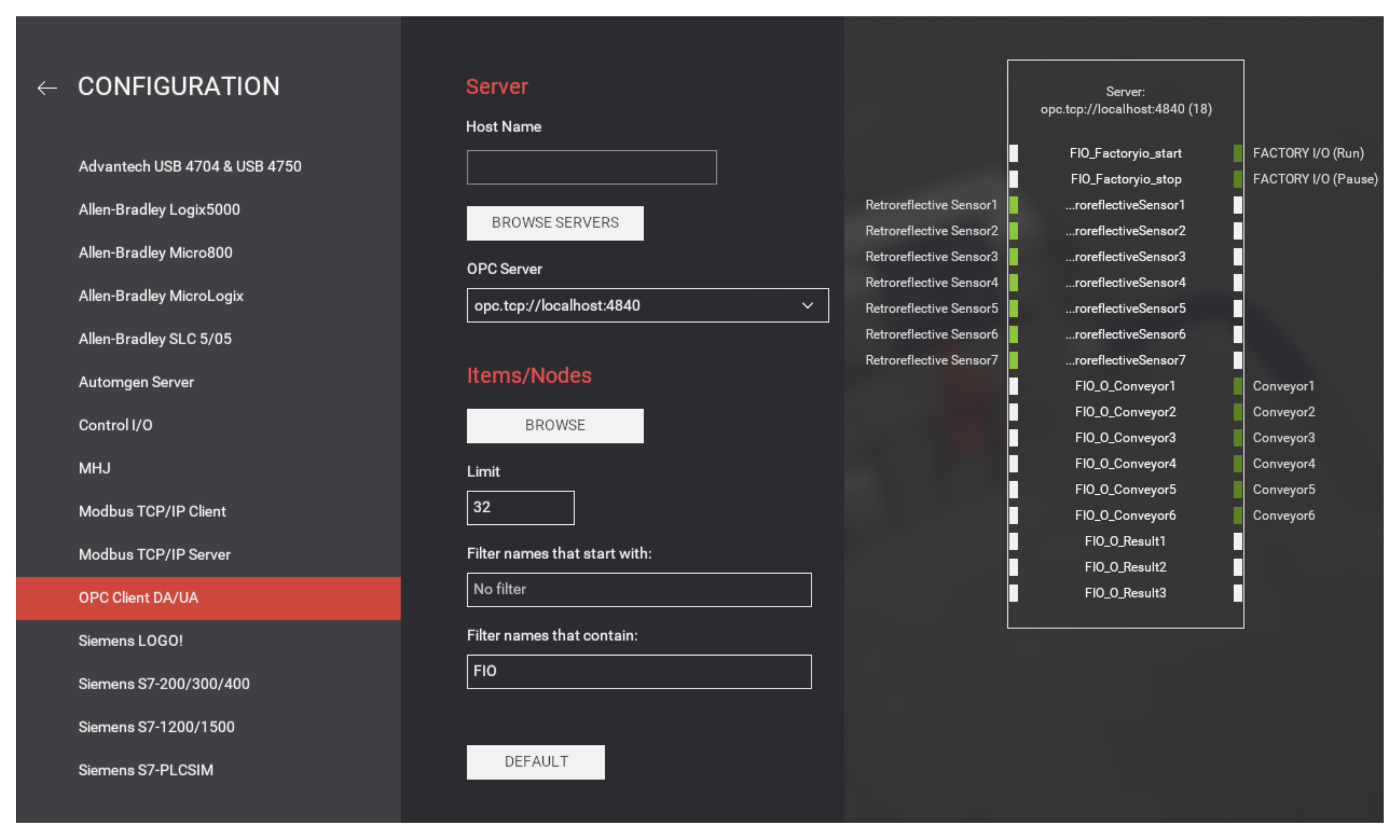
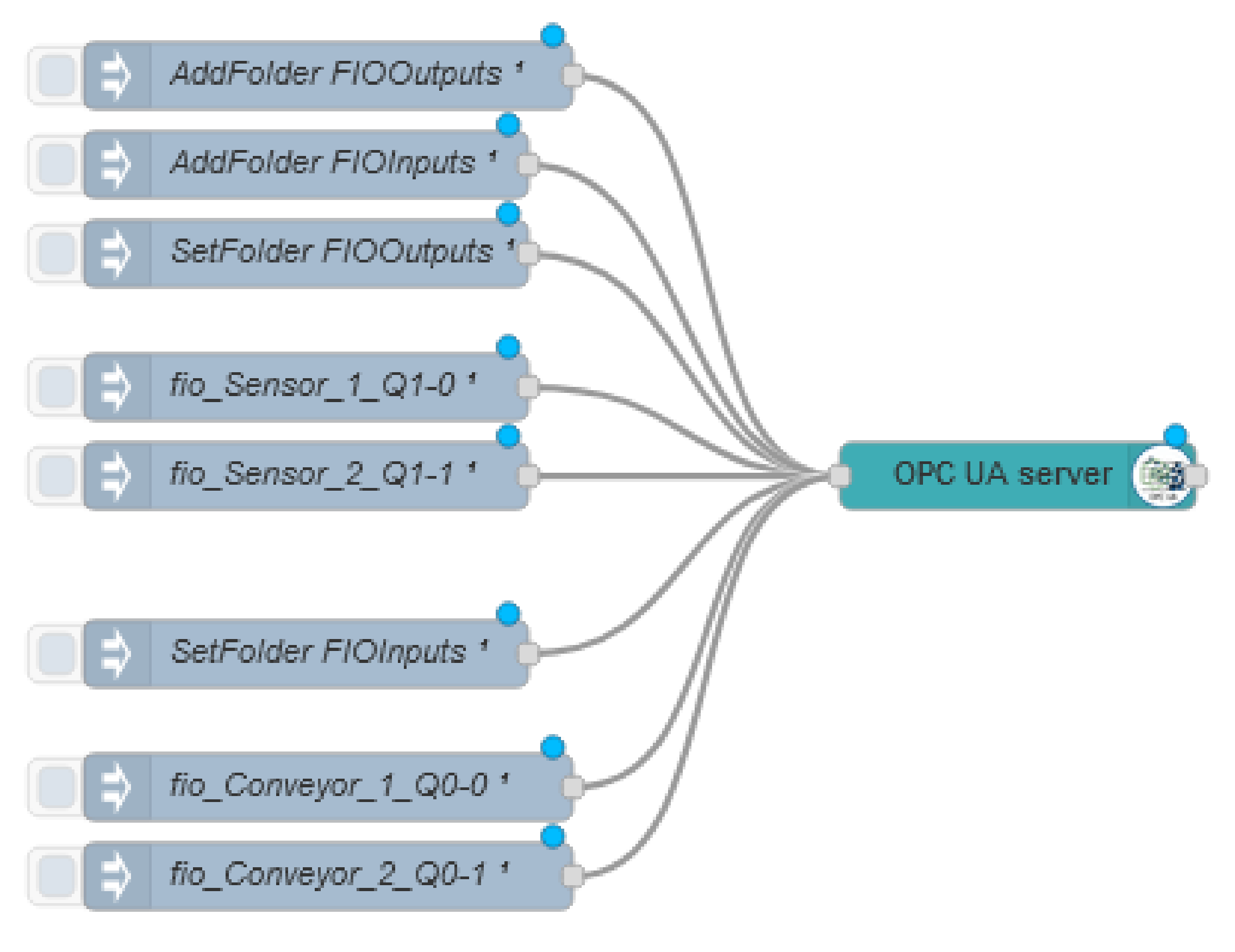
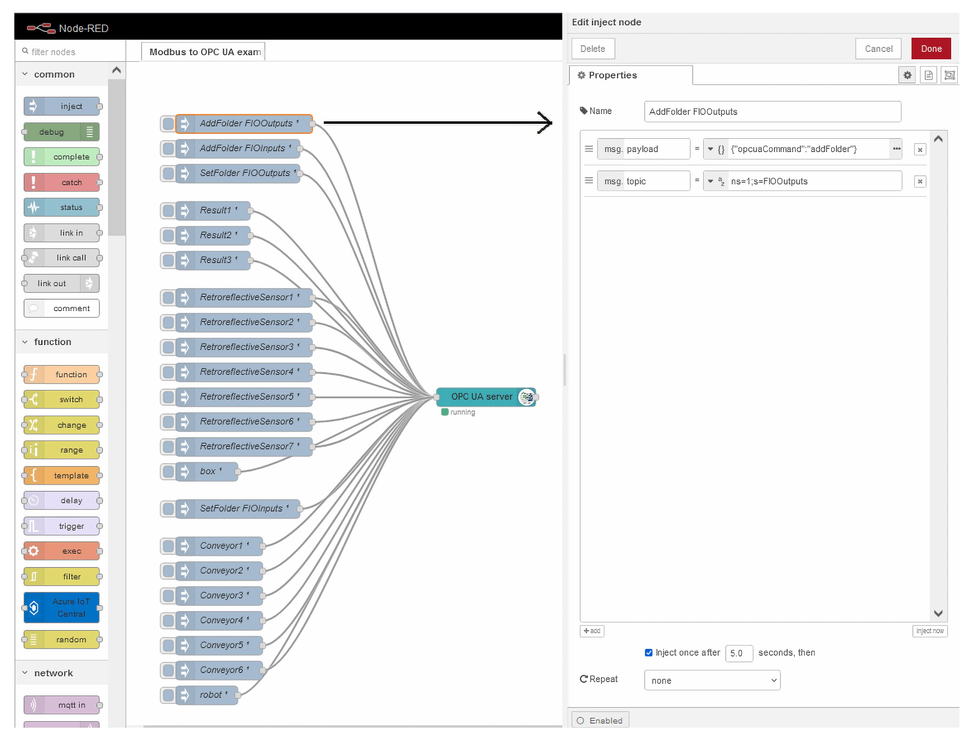
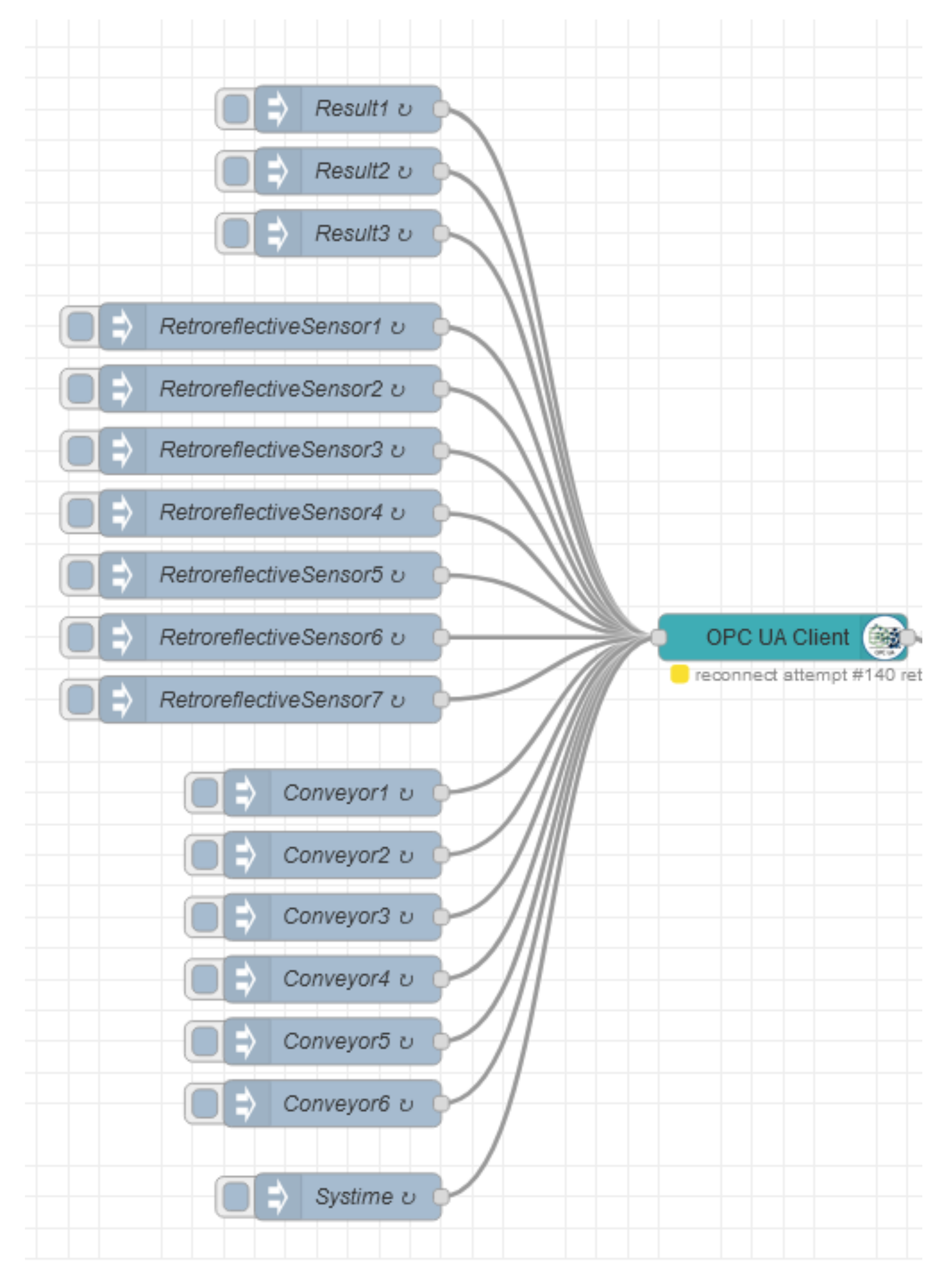
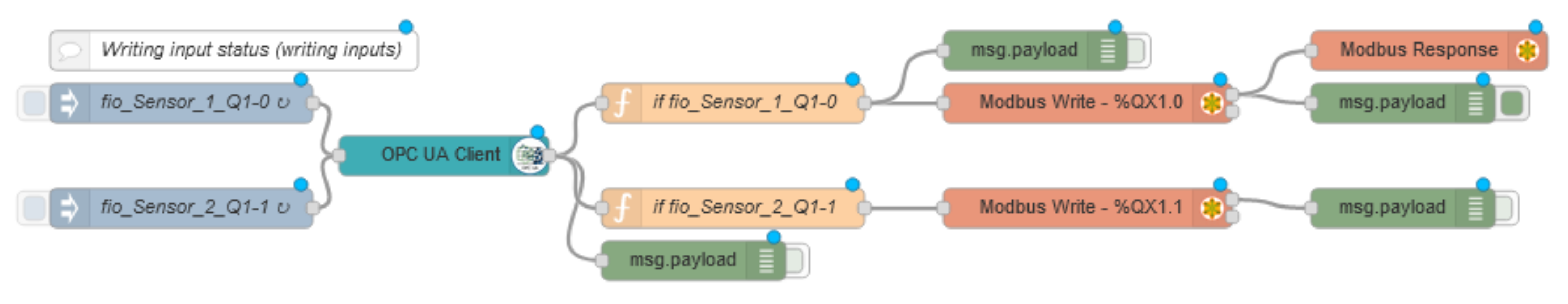
6.1.4. OPC UA Server and Client
- msg.payload: {”opcuaCommand“:”addVariable”};
- msg.topic: ns=1;s=RetroreflectiveSensor1;datatype=Boolean.
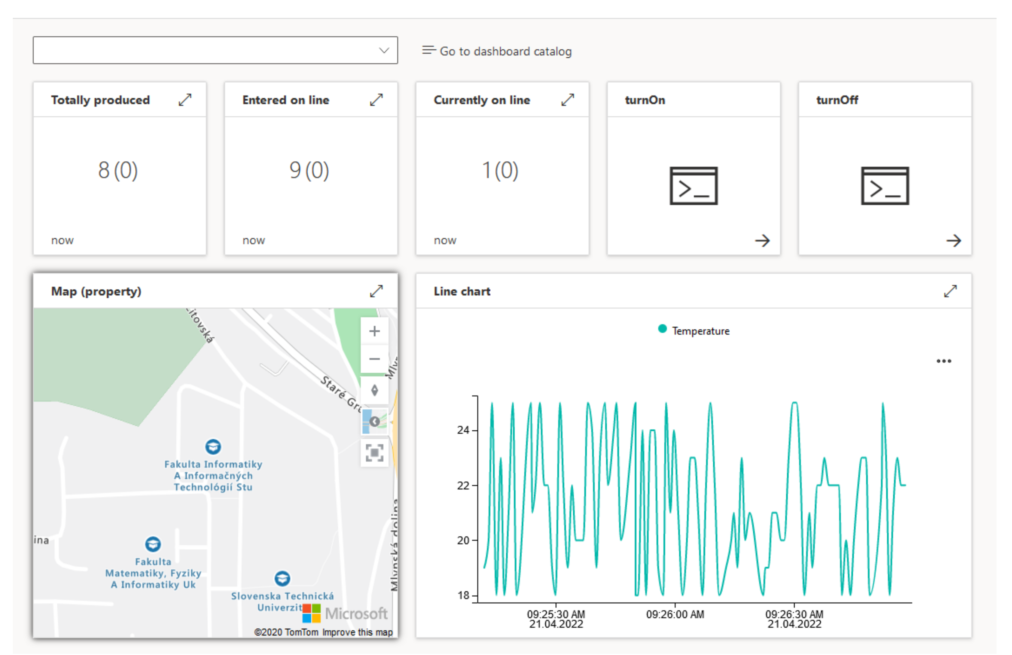
6.1.5. Application in Microsoft Azure Cloud
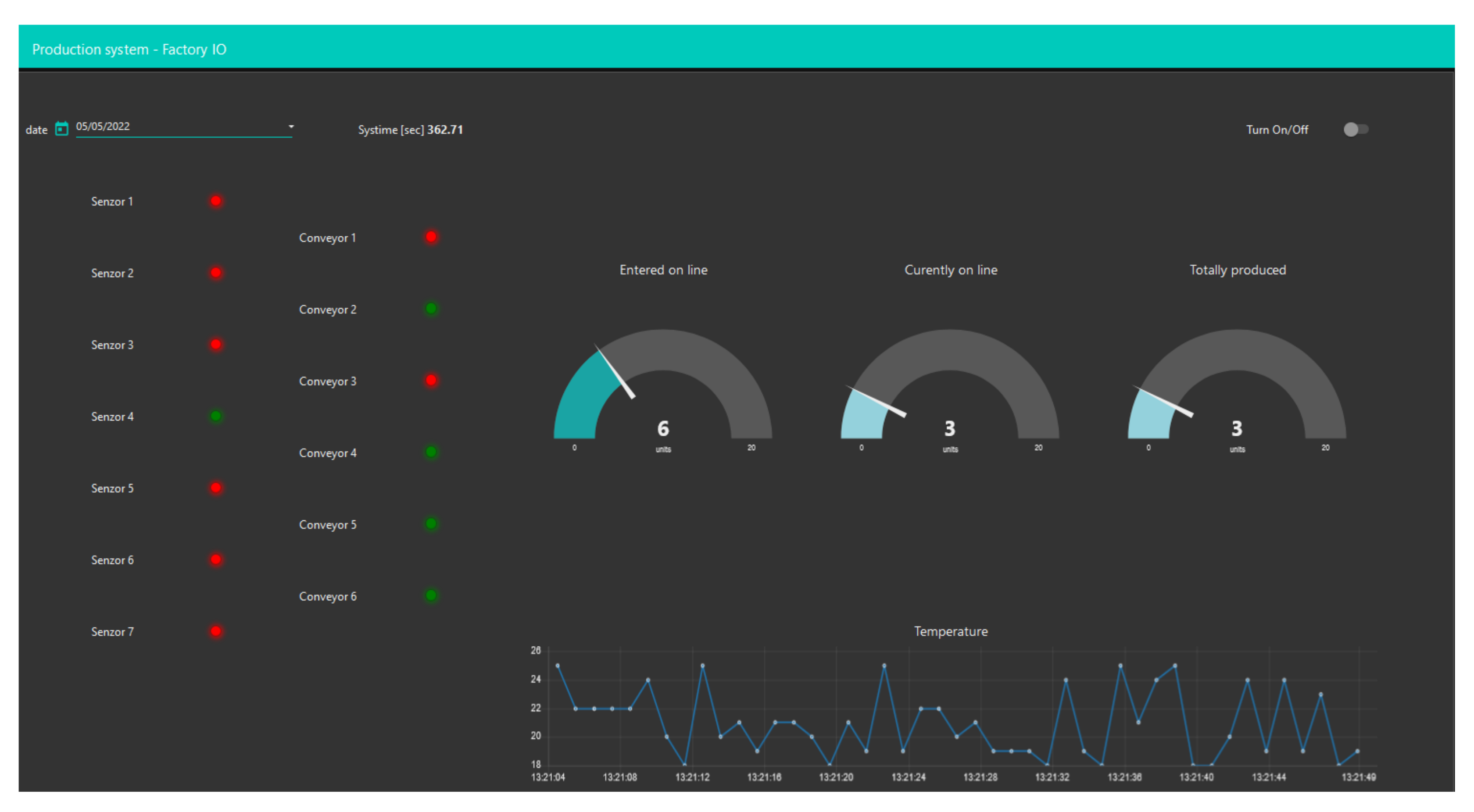
- Display of read values and action buttons in a dashboard;
- Communication with Node-RED using the MQTT protocol;
- Display of the number of manufactured (final) products handed over for dispatch;
- Displaying the number of semi-finished products (pieces of raw material) that have entered production;
- Displaying the number of semi-finished products/finished products that are currently on the conveyors (or in the system as such);
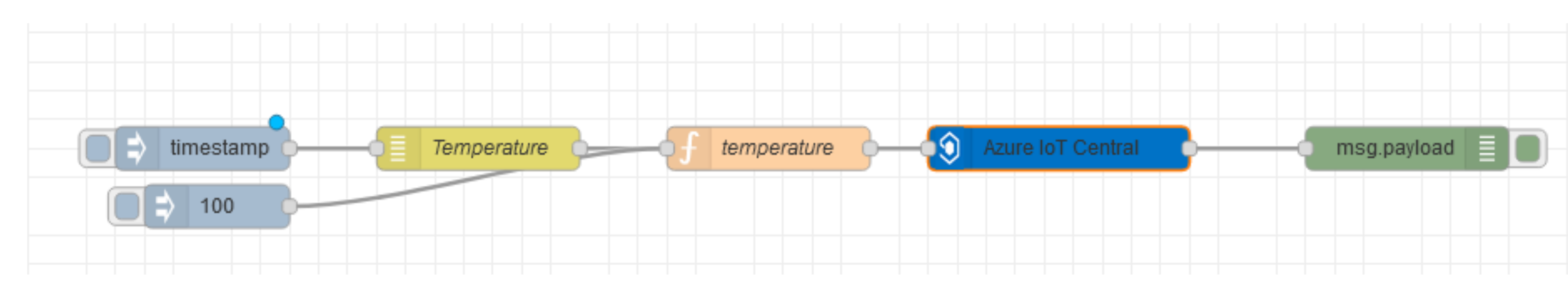
- Graphical representation of the current temperature in the production hall;
- Simple processing of the current temperature values in the production hall in order to raise an alarm if the temperature rises above a certain value;
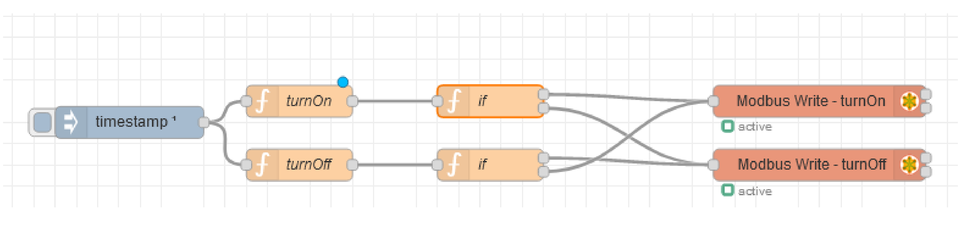
- Possibility of emergency intervention in the system-suspension and start-up of the production line.
- The cloud application should have a simple and intuitive user interface;
- Individual displayed variables should be part of a suitable object model, assuming appropriate use of Microsoft Azure cloud components;
- The application should allow for easy extensibility by displaying additional variables, or the possibility of adding additional production lines, each with its own panel;
- In terms of language internationalisation, the application should use English.
- properties—data fields that represent the state of the device;
- telemetry—telemetry (measurements) from sensors;
- command—methods that users can execute on the device (e.g., control commands).
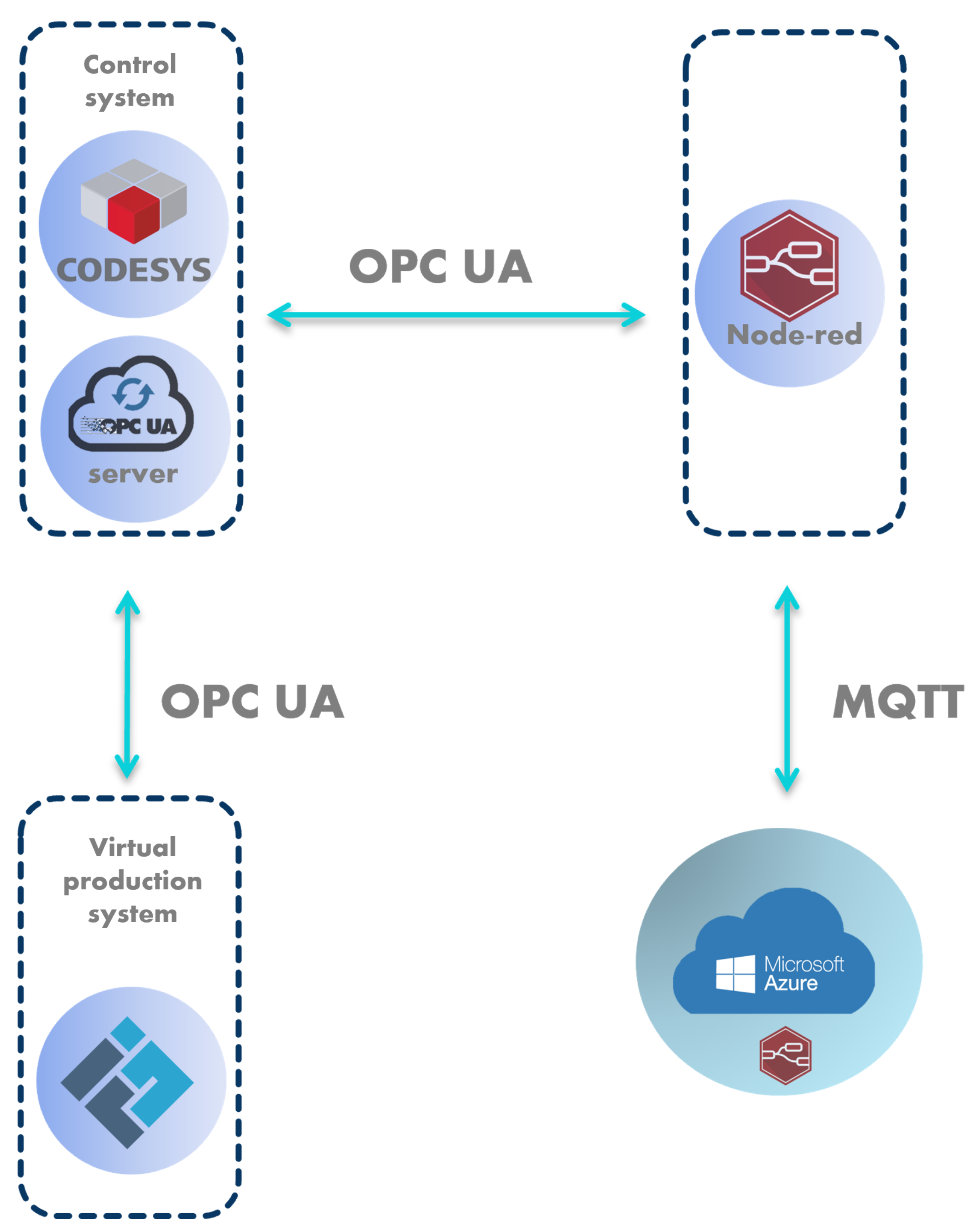
6.2. Case Study No. 2: CODESYS Linked with Node-RED and Microsoft Azure
6.2.1. Control of Discrete-Event System
6.2.2. Communication
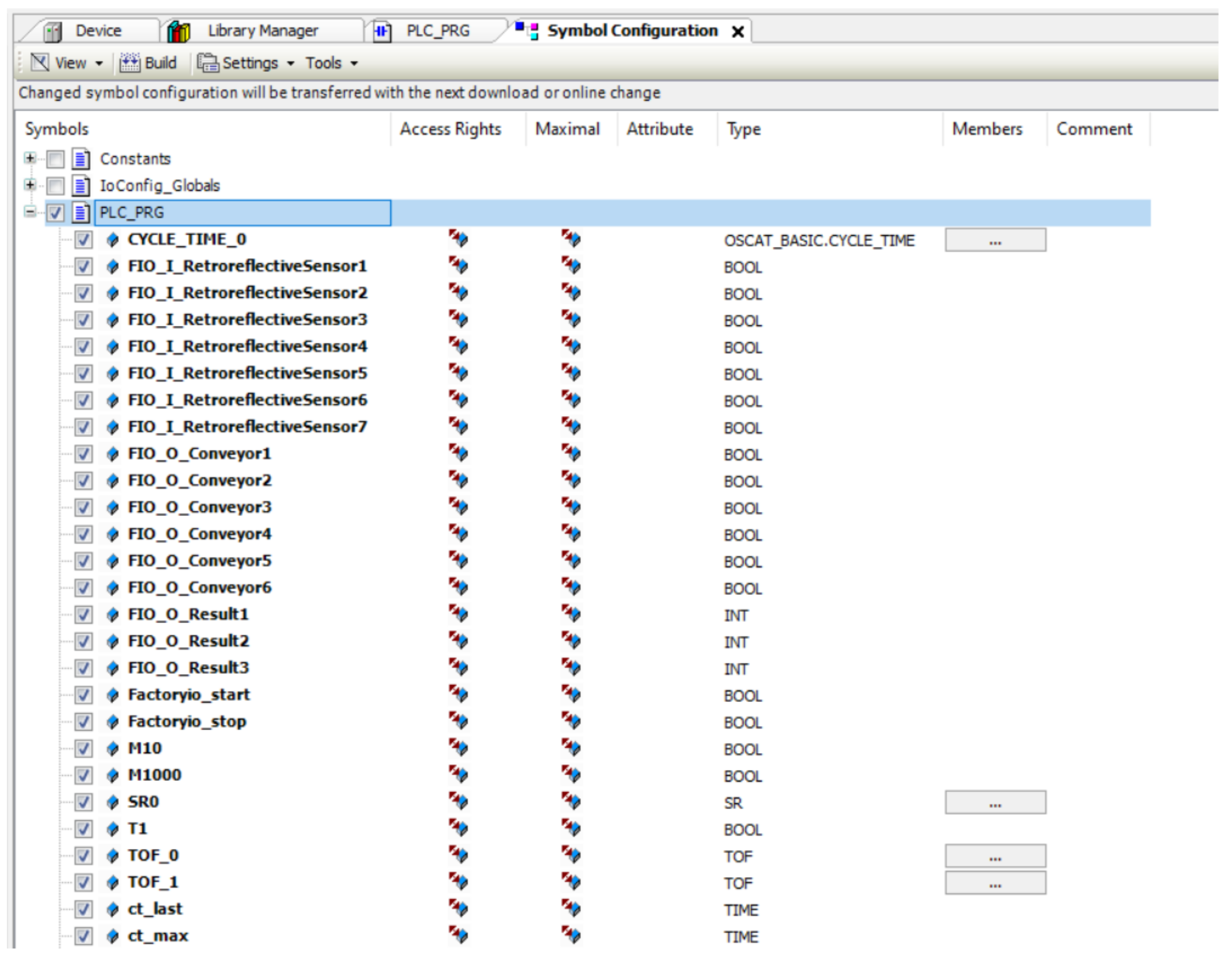
6.2.3. OPC UA Server in CODESYS
6.2.4. Connection between CODESYS and Local Node-RED
6.2.5. Node-RED Dashboard in Microsoft Azure Cloud
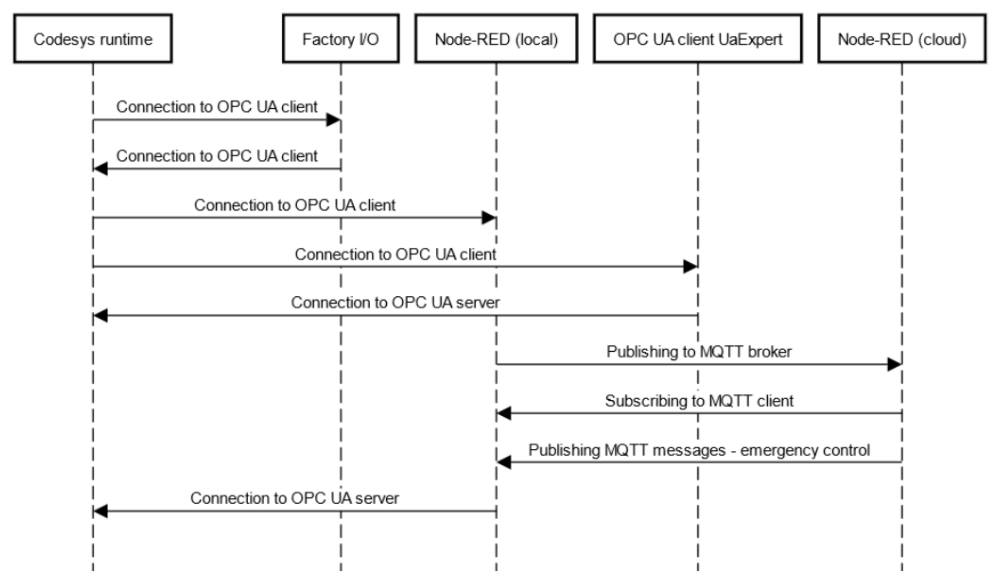
6.3. Case Study No. 3: OpenPLC Linked with Node-RED Acting as a Software IIoT Gateway
6.3.1. Control of Discrete-Event System
6.3.2. Communication
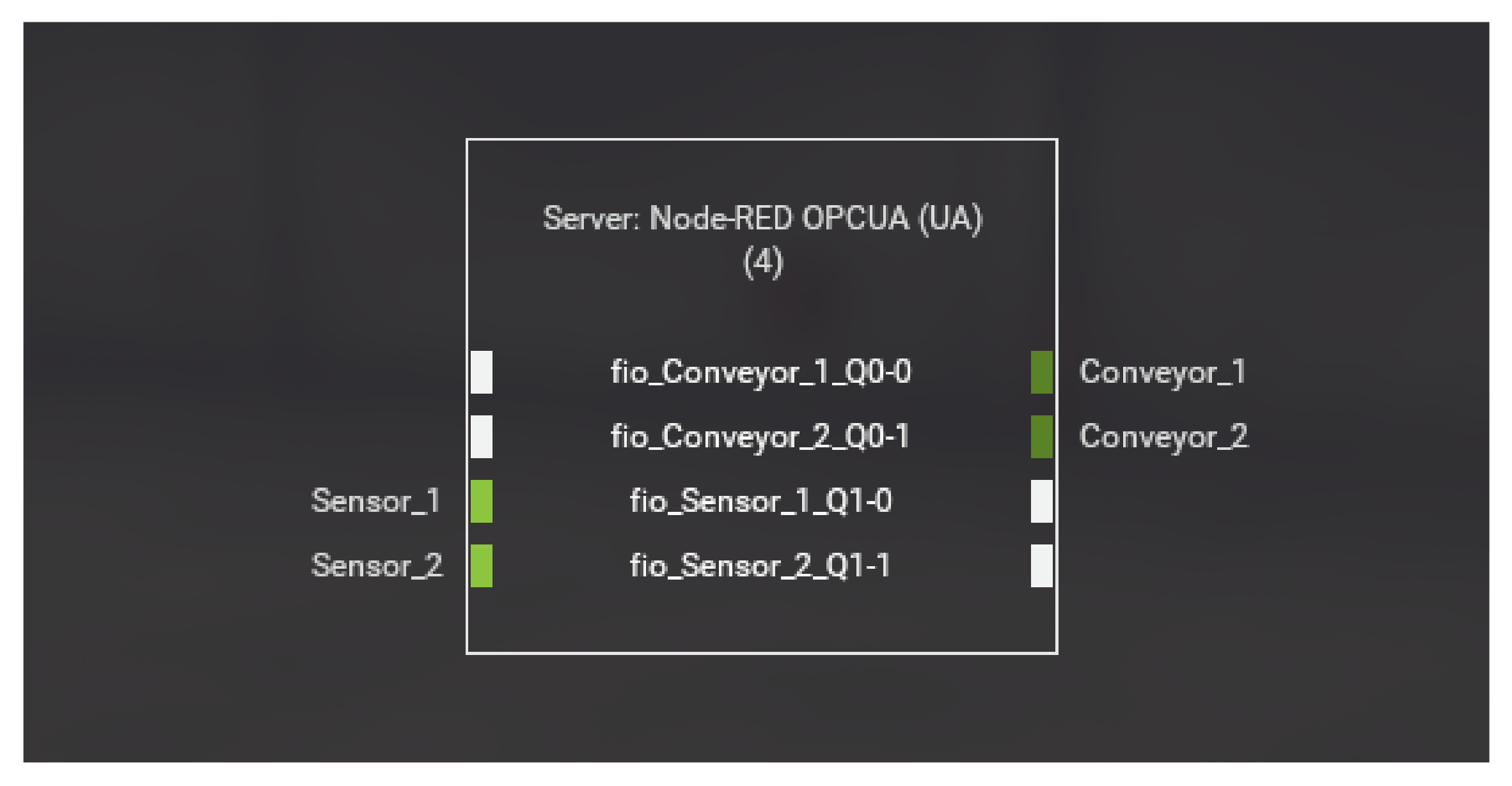
6.3.3. Creation of OPC UA Server in Node-RED
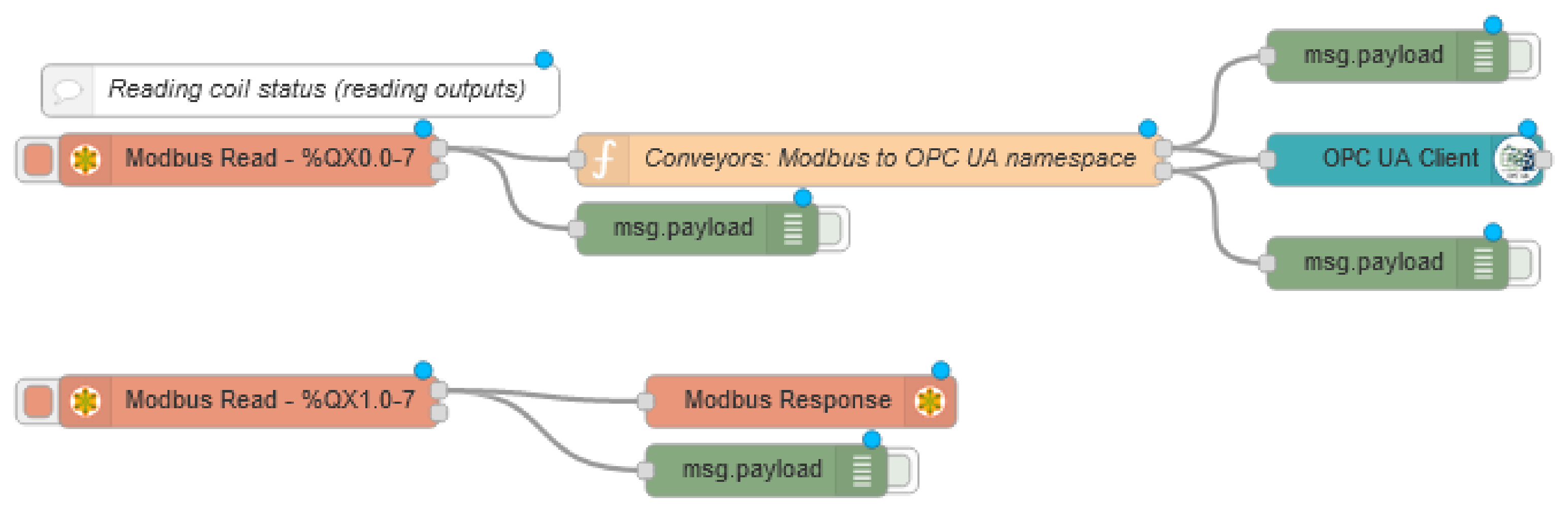
6.3.4. Communication from OpenPLC to Factory I/O
6.3.5. Communication from Factory I/O to OpenPLC
7. Discussion of Results
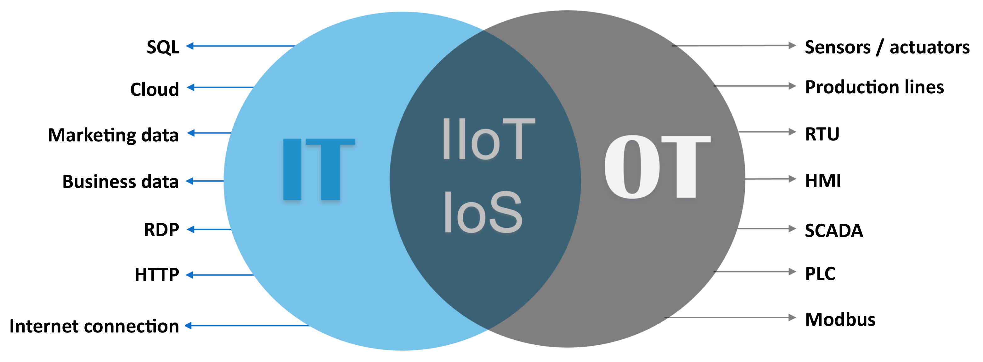
- People focused on IT—computer engineers, software engineers, programmers, etc.
- People focused on OT—automation engineers, mechatronics engineers, PLC programmers, etc.
- Motivational introduction
- Importance of IT and OT convergence, key aspects.
- Basic IT concepts
- Review of basic programming paradigms, functions, objects;
- Object-oriented programming;
- Cloud computing—basic aspects.
- Basic OT concepts
- Systems theory, overview of different types of cyber-physical systems, discrete-event systems;
- Programming languages for PLC;
- PLC programming.
- Core of the course—convergence of IT and OT
- Simulation tool Factory I/O;
- Industry 4.0 concept, Reference Architectural Model Industrie 4.0 (RAMI 4.0);
- OPC Unified Architecture;
- Node-RED: basic programming;
- Node-RED: communication with cloud and using OPC UA and MQTT;
- Cloud computing—Microsoft Azure.
8. Conclusions
- Modelling and control of virtual discrete-event systemA virtual model of a production discrete-event system was created within the work, which was inspired by a real model available at the Institute of Automotive Mechatronics FEI STU in Bratislava, Slovakia. The control programs were created using ladder diagrams and were implemented using two development environments—OpenPLC and CODESYS.
- Design and implementation of cloud applicationsTwo cloud-based applications were designed and implemented for monitoring and emergency intervention of the production discrete-event system. The cloud applications were implemented in different ways. In the first case, the aPaaS service Azure IoT Central was used and in the second case, the IaaS service Azure Virtual Machine was used. This is an Ubuntu Linux based virtual machine where a dashboard (graphical user interface) created using Node-RED was deployed.
- Implementation of a software IIoT gateway applicable for edge computingIn the last case study, it was necessary to encapsulate data arriving via the Modbus protocol in the address space of OPC UA. This is commonly handled using hardware IIoT gateways or similar network elements. However, our solution is to implement a software IIoT gateway using the flow-oriented programming tool Node-RED, and this type of application can also be implemented in affordable microcomputers (e.g., Raspberry Pi). We can then place such a microcomputer at the edge of the network as an edge device.
- Creation of the basis for pilot projects for the creation of educational materials for the training of engineers for Industry 4.0—pilot Engineer 4.0 programmesThe nature of the prepared case studies, which combine operational and information technologies, predestines them to be used in the sphere of the education of engineers for the digitalisation of production processes.
Author Contributions
Funding
Institutional Review Board Statement
Informed Consent Statement
Data Availability Statement
Acknowledgments
Conflicts of Interest
References
- Kamal, S.; Al Mubarak, S.; Scodova, B.; Naik, P.; Flichy, P.; Coffin, G. IT and OT convergence-Opportunities and challenges. In Proceedings of the SPE Intelligent Energy International Conference and Exhibition, Aberdeen, Scotland, UK, 6–8 September 2016. [Google Scholar]
- Shahroom, A.; Hussin, N. Industrial Revolution 4.0 and Education. Int. J. Acad. Res. Bus. Soc. Sci. 2018, 8, 314–319. [Google Scholar] [CrossRef]
- González-Pérez, L.I.; Ramírez-Montoya, M.S. Components of Education 4.0 in 21st Century Skills Frameworks: Systematic Review. Sustainability 2022, 14, 1493. [Google Scholar] [CrossRef]
- Information Technology (in German). Available online: https://theastrologypage.com/information-technology (accessed on 26 April 2022).
- Operational Technology. Available online: https://www.gartner.com/en/information-technology/glossary/operational-technology-ot (accessed on 26 April 2022).
- What’s the Difference between IT and OT? Available online: https://www.3pillarglobal.com/insights/how-does-iiot-bring-it-and-ot-together/ (accessed on 26 April 2022).
- Huba, M.; Kozák, Š. From E-learning to Industry 4.0. In Proceedings of the 2016 International Conference on Emerging e-Learning Technologies and Applications (ICETA), Stary Smokovec, Slovakia, 24–25 November 2016; pp. 103–108. [Google Scholar]
- Leiden, A.; Posselt, G.; Bhakar, V.; Singh, R.; Sangwan, K.; Herrmann, C. Transferring experience labs for production engineering students to universities in newly industrialized countries. In Proceedings of the IOP Conference Series: Materials Science and Engineering (TSME-ICoME 2017), Bangkok, Thailand, 12–15 December 2017; Volume 297, p. 012053. [Google Scholar]
- Souza, R.G.d.; Quelhas, O.L.G. Model proposal for diagnosis and integration of industry 4.0 concepts in production engineering courses. Sustainability 2020, 12, 3471. [Google Scholar] [CrossRef]
- Assante, D.; Caforio, A.; Flamini, M.; Romano, E. Smart Education in the context of Industry 4.0. In Proceedings of the 2019 IEEE Global Engineering Education Conference (EDUCON), Dubai, United Arab Emirates, 8–11 April 2019; pp. 1140–1145. [Google Scholar]
- Sackey, S.M.; Bester, A. Industrial engineering curriculum in Industry 4.0 in a South African context. S. Afr. J. Ind. Eng. 2016, 27, 101–114. [Google Scholar] [CrossRef]
- Ciolacu, M.; Svasta, P.M.; Berg, W.; Popp, H. Education 4.0 for tall thin engineer in a data driven society. In Proceedings of the 2017 IEEE 23rd International Symposium for Design and Technology in Electronic Packaging (SIITME), Constanta, Romania, 26–29 October 2017; pp. 432–437. [Google Scholar]
- Pierleoni, P.; Belli, A.; Palma, L.; Sabbatini, L. A versatile machine vision algorithm for real-time counting manually assembled pieces. J. Imaging 2020, 6, 48. [Google Scholar] [CrossRef] [PubMed]
- Merkulova, I.Y.; Shavetov, S.V.; Borisov, O.I.; Gromov, V.S. Object detection and tracking basics: Student education. IFAC-PapersOnLine 2019, 52, 79–84. [Google Scholar]
- Dr, P.; Kumar, P.; Johri, P.; Srivastava, S.; Suhag, S. A Comparative Study of Industry 4.0 with Education 4.0. In Proceedings of the 4th International Conference: Innovative Advancement in Engineering Technology (IAET), Jaipur, India, 21–22 February 2020. [Google Scholar] [CrossRef]
- Hussin, A.A. Education 4.0 Made Simple: Ideas For Teaching. Int. J. Educ. Lit. Stud. 2018, 6, 92–98. [Google Scholar] [CrossRef]
- Coşkun, S.; Kayıkcı, Y.; Gençay, E. Adapting Engineering Education to Industry 4.0 Vision. Technologies 2019, 7, 10. [Google Scholar] [CrossRef]
- Mian, S.H.; Salah, B.; Ameen, W.; Moiduddin, K.; Alkhalefah, H. Adapting Universities for Sustainability Education in Industry 4.0: Channel of Challenges and Opportunities. Sustainability 2020, 12, 6100. [Google Scholar] [CrossRef]
- Grenčiková, A.; Kordoš, M.; Navickas, V. The impact of Industry 4.0 on education contents. Business Theory Pract. 2021, 22, 29–38. [Google Scholar] [CrossRef]
- Produktion2030 Ingenjör4.0. Available online: https://produktion2030.se/en/ingenjor-4-0/ (accessed on 27 December 2021).
- Chanthakit, S.; Rattanapoka, C. Mqtt based air quality monitoring system using node MCU and node-red. In Proceedings of the 2018 Seventh ICT International Student Project Conference (ICT-ISPC), Nakhonpathom, Thailand, 11–13 July 2018; pp. 1–5. [Google Scholar]
- Langmann, R.; Stiller, M. The PLC as a Smart Service in Industry 4.0 Production Systems. Appl. Sci. 2019, 9, 3815. [Google Scholar] [CrossRef]
- Ferrari, P.; Flammini, A.; Rinaldi, S.; Sisinni, E.; Maffei, D.; Malara, M. Impact of Quality of Service on Cloud Based Industrial IoT Applications with OPC UA. Electronics 2018, 7, 109. [Google Scholar] [CrossRef]
- Lakhan, A.; Mohammed, M.A.; Abdulkareem, K.H.; Jaber, M.M.; Nedoma, J.; Martinek, R.; Zmij, P. Delay Optimal Schemes for Internet of Things Applications in Heterogeneous Edge Cloud Computing Networks. Sensors 2022, 22, 5937. [Google Scholar] [CrossRef] [PubMed]
- Indexed Line with Two Machining Stations 24V—Simulation. Available online: https://www.fischertechnik.de/en/products/simulating/training-models/96790-sim-indexed-line-with-two-machining-stations-24v-simulation (accessed on 27 April 2022).
- Pajpach, M.; Haffner, O.; Kučera, E.; Drahoš, P. Low-Cost Education Kit for Teaching Basic Skills for Industry 4.0 Using Deep-Learning in Quality Control Tasks. Electronics 2022, 11, 230. [Google Scholar] [CrossRef]
- Factory IO. Available online: https://docs.factoryio.com/ (accessed on 27 April 2022).
- OpenPLC Editor. Available online: https://openplcproject.com/docs/3-1-openplc-editor-overview/ (accessed on 26 April 2022).
- Philip Samuel, A.K.; Shyamkumar, A.; Ramesh, H. Industry 4.0-Connected Drives Using OPC UA. In Industry 4.0 and Advanced Manufacturing; Chakrabarti, A., Arora, M., Eds.; Springer: Singapore, 2021; pp. 3–12. [Google Scholar]
- Modbus Address Mapping. Available online: https://openplcproject.com/docs/2-5-modbus-addressing/ (accessed on 26 April 2022).
- Azure IoT Hub. Available online: https://azure.microsoft.com/en-us/services/iot-hub/ (accessed on 27 July 2022).
- Power BI. Available online: https://powerbi.microsoft.com/en-us/ (accessed on 27 July 2022).
- Azure Stream Analytics. Available online: https://azure.microsoft.com/en-us/services/stream-analytics/ (accessed on 27 July 2022).
- Azure Functions. Available online: https://docs.microsoft.com/en-us/azure/azure-functions/ (accessed on 27 July 2022).
- Azure IoT Central. Available online: https://azure.microsoft.com/en-us/services/iot-central/ (accessed on 27 July 2022).
- Aedes MQTT Broker. Available online: https://github.com/moscajs/aedes (accessed on 27 July 2022).
- Azure Virtual Machines. Available online: https://azure.microsoft.com/en-us/services/virtual-machines/ (accessed on 27 July 2022).


| Modbus Table | Usage | PLC Address | Modbus Data Address | Data Size | Range | Access |
|---|---|---|---|---|---|---|
| Discrete Output Coils | Digital Outputs | %QX0.0–%QX99.7 | 0–799 | 1 bit | 0 or 1 | RW |
| Discrete Input Coils | Digital Inputs | %IX0.0–%IX99.7 | 0–799 | 1 bit | 0 or 1 | R |
| Analog Input Registers | Analog Input | %IW0–%IW1023 | 0–1023 | 16 bits | 0–65,535 | R |
| Analog Output Holding registers | Analog Outputs | %QW0–%QW1023 | 0–1023 | 16 bits | 0–65,535 | RW |
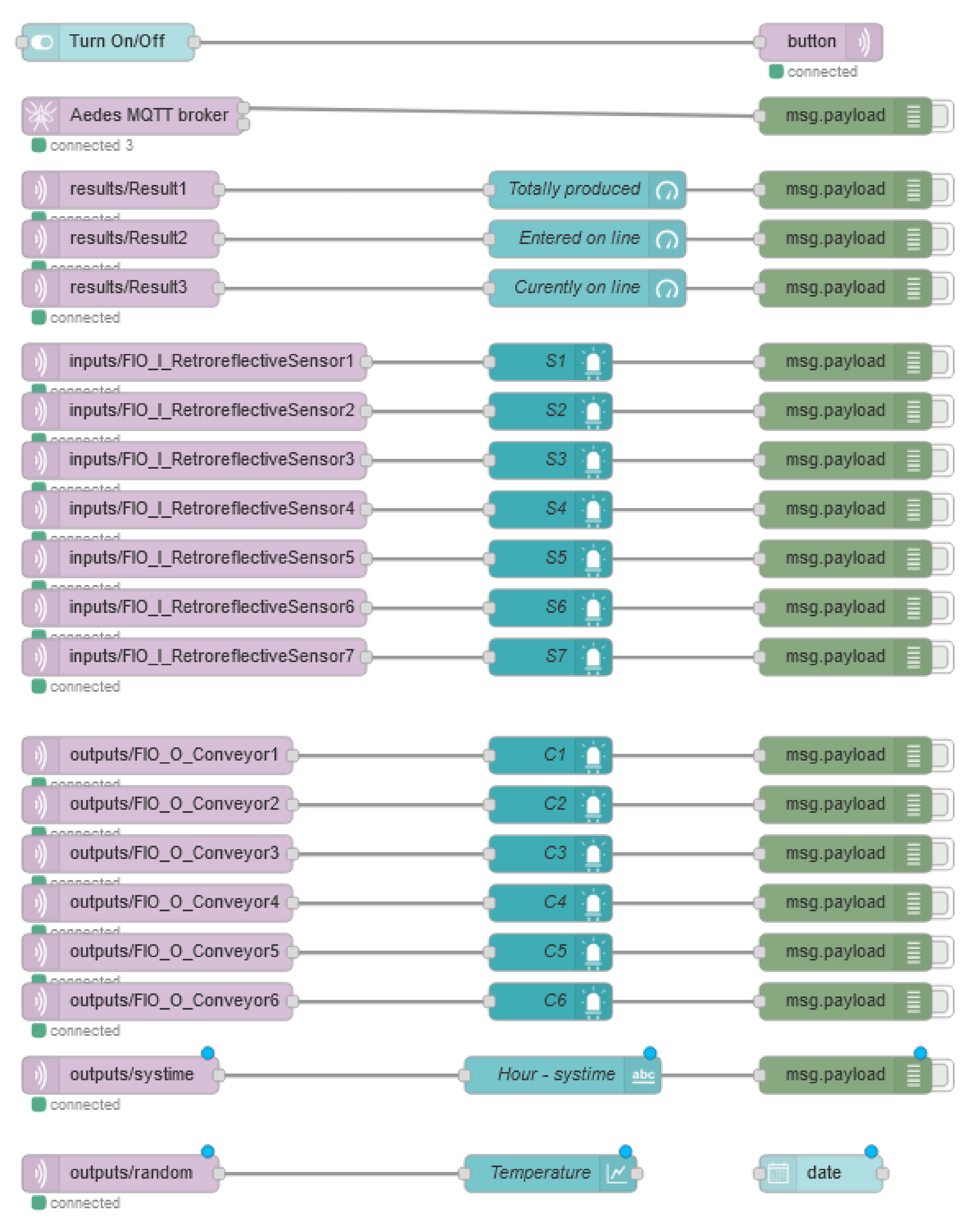
| Node Type | Node Name |
|---|---|
| led | S1–S7, C1–C6 |
| gauge | Totally produced, Entered on line, Curently on line |
| text | Systime |
| chart | Temperature |
| button | Turn On/Off |
| date picker | date |
Publisher’s Note: MDPI stays neutral with regard to jurisdictional claims in published maps and institutional affiliations. |
© 2022 by the authors. Licensee MDPI, Basel, Switzerland. This article is an open access article distributed under the terms and conditions of the Creative Commons Attribution (CC BY) license (https://creativecommons.org/licenses/by/4.0/).
Share and Cite
Kučera, E.; Haffner, O.; Drahoš, P.; Cigánek, J. Educational Case Studies for Pilot Engineer 4.0 Programme: Monitoring and Control of Discrete-Event Systems Using OPC UA and Cloud Applications. Appl. Sci. 2022, 12, 8802. https://doi.org/10.3390/app12178802
Kučera E, Haffner O, Drahoš P, Cigánek J. Educational Case Studies for Pilot Engineer 4.0 Programme: Monitoring and Control of Discrete-Event Systems Using OPC UA and Cloud Applications. Applied Sciences. 2022; 12(17):8802. https://doi.org/10.3390/app12178802
Chicago/Turabian StyleKučera, Erik, Oto Haffner, Peter Drahoš, and Ján Cigánek. 2022. "Educational Case Studies for Pilot Engineer 4.0 Programme: Monitoring and Control of Discrete-Event Systems Using OPC UA and Cloud Applications" Applied Sciences 12, no. 17: 8802. https://doi.org/10.3390/app12178802
APA StyleKučera, E., Haffner, O., Drahoš, P., & Cigánek, J. (2022). Educational Case Studies for Pilot Engineer 4.0 Programme: Monitoring and Control of Discrete-Event Systems Using OPC UA and Cloud Applications. Applied Sciences, 12(17), 8802. https://doi.org/10.3390/app12178802