
Thermoplastic Materials for the Metal Replacement of Non-Structural Components in Marine Engines

 ,
,  ,
,  , and
, and 
Abstract
:1. Introduction
2. Materials and Methods
2.1. Materials
2.1.1. Material Design
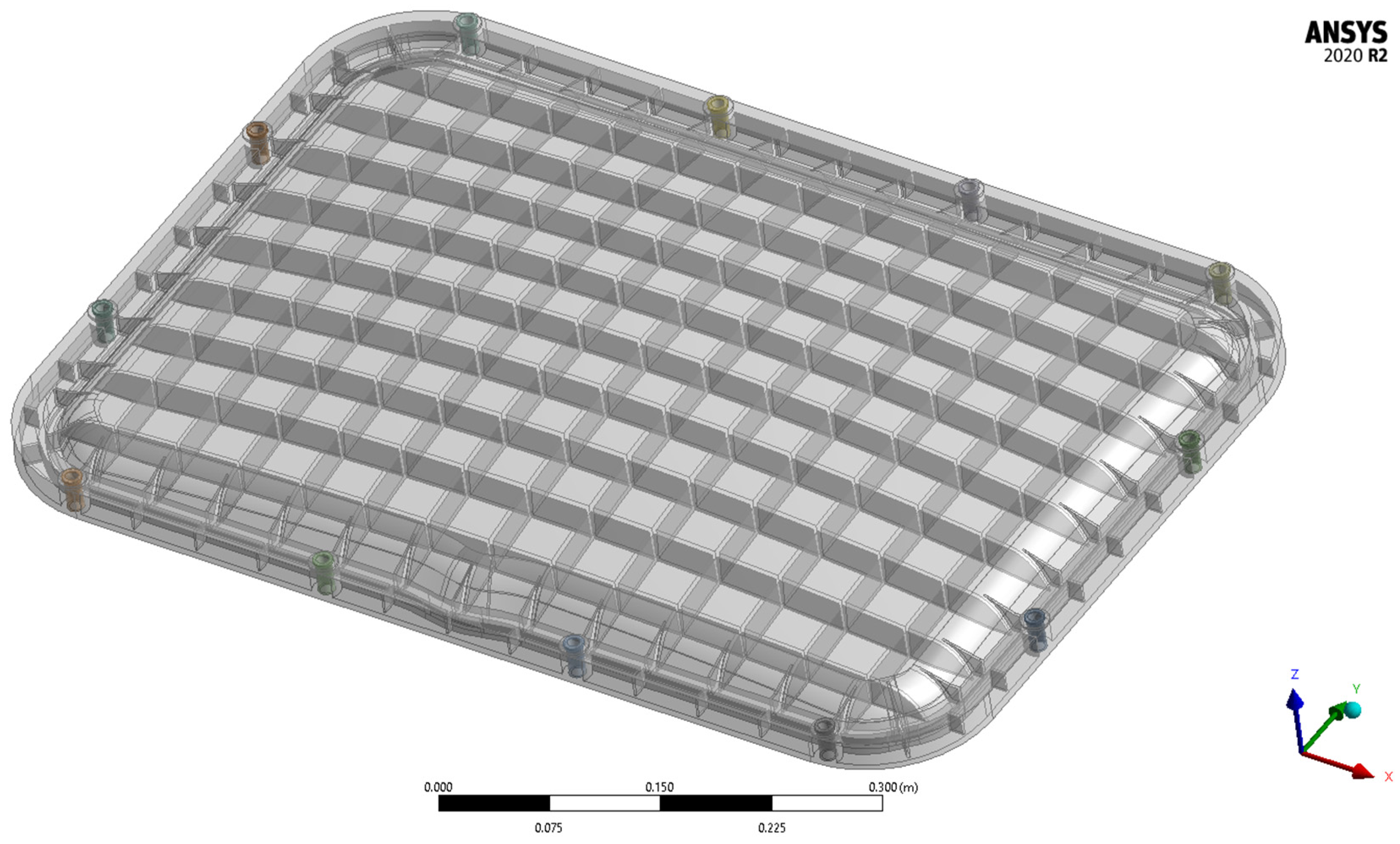
2.1.2. Case-Study Component: Camshaft Cover
2.2. Methods
2.2.1. Model Redesign and Material Characterisation
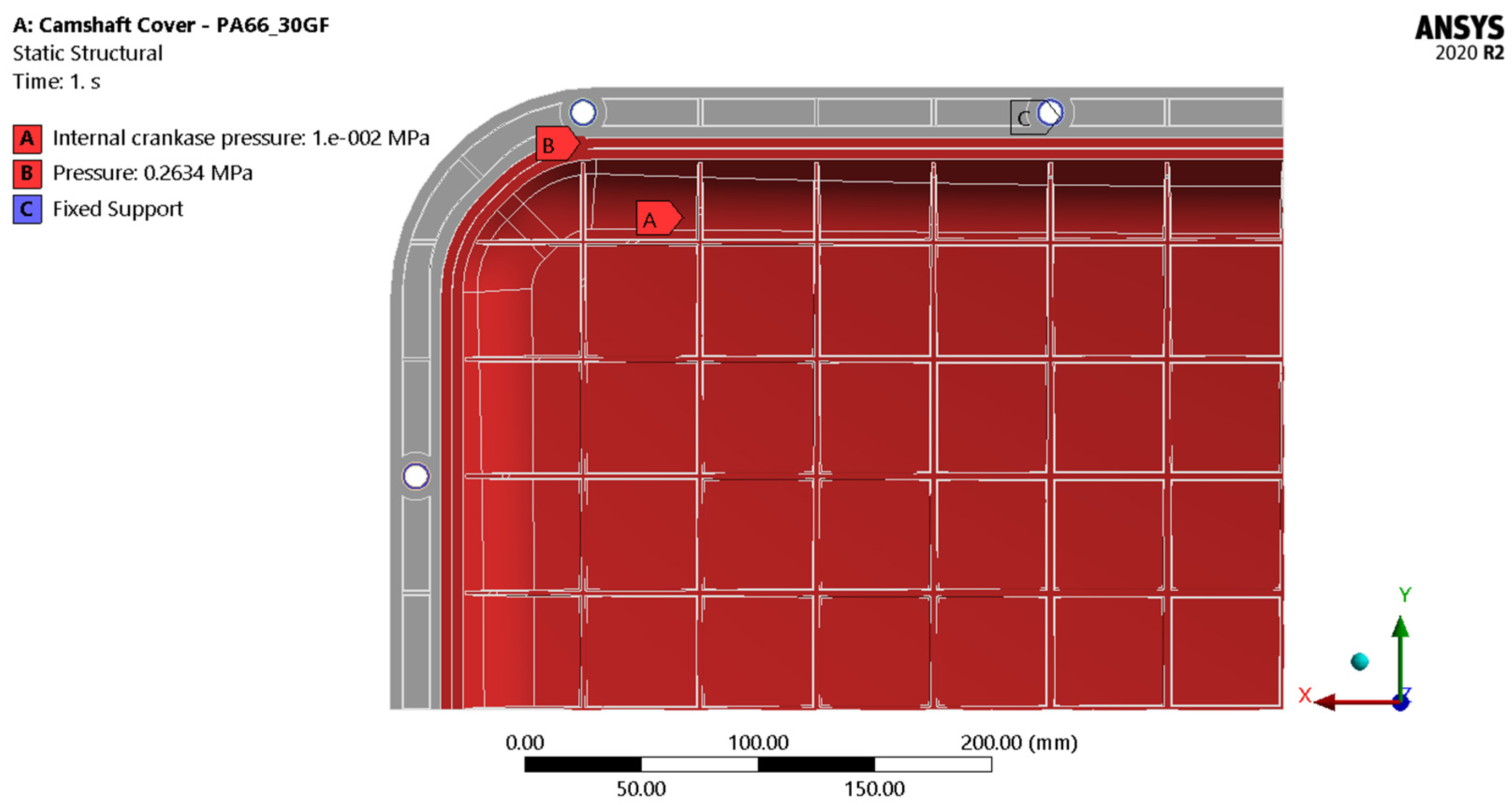
2.2.2. Finite Element Simulations
3. Results and Discussion
4. Conclusions
Author Contributions
Funding
Acknowledgments
Conflicts of Interest
Appendix A
Computational Details

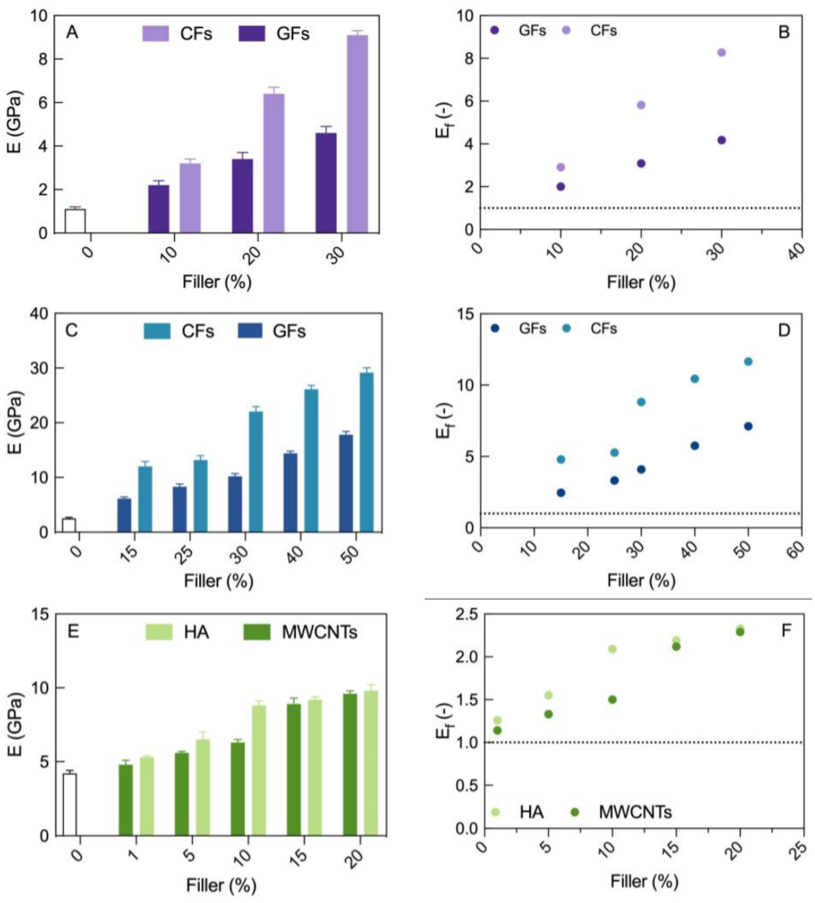
| System | E (GPa) | Ef (-) | System | E (GPa) | Ef (-) |
|---|---|---|---|---|---|
| PA6 | 1.1 ± 0.1 | ||||
| 10% wt GFs/PA6 | 2.2 ± 0.2 | 2.0 | 10% wt CF/PA6 | 3.2 ± 0.2 | 2.9 |
| 20% wt GFs/PA6 | 3.4 ± 0.3 | 3.1 | 20% wt CF/PA6 | 6.4 ± 0.3 | 5.8 |
| 30% wt GFs/PA6 | 4.6 ± 0.3 | 4.2 | 30% wt CF/PA6 | 9.1 ± 0.2 | 8.3 |
| System | E (GPa) | Ef (-) | System | E (GPa) | Ef (-) |
|---|---|---|---|---|---|
| PA6,6 | 2.5 ± 0.2 | ||||
| 10% wt GFs/PA6,6 | 6.1 ± 0.3 | 2.5 | 10% wt CF/PA6,6 | 12.0 ± 0.9 | 4.8 |
| 20% wt GFs/PA6,6 | 8.3 ± 0.5 | 3.3 | 20% wt CF/PA6,6 | 13.2 ± 0.8 | 5.3 |
| 30% wt GFs/PA6,6 | 10.2 ± 0.5 | 4.1 | 30% wt CF/PA6,6 | 22.1 ± 0.9 | 8.8 |
| 40% wt GFs/PA6,6 | 14.4 ± 0.4 | 5.8 | 40% wt CF/PA6,6 | 26.1 ± 0.7 | 10.4 |
| 50% wt GFs/PA6,6 | 17.8 ± 0.6 | 7.1 | 50% wt CF/PA6,6 | 29.1 ± 0.9 | 11.7 |
| System | E (GPa) | Ef (-) | System | E (GPa) | Ef (-) |
|---|---|---|---|---|---|
| PEEK | 4.2 ± 0.2 | ||||
| 1% wt MWCNTs/PEEK | 4.8 ± 0.3 | 1.1 | 1% wt HA/PEEK | 5.3 ± 0.1 | 1.3 |
| 5% wt MWCNTs/PEEK | 5.6 ± 0.1 | 1.3 | 5% wt HA/PEEK | 6.5 ± 0.5 | 1.6 |
| 10% wt MWCNTs/PEEK | 6.3 ± 0.2 | 1.5 | 10% wt HA/PEEK | 8.8 ± 0.3 | 2.1 |
| 15% wt MWCNTs/PEEK | 8.9 ± 0.4 | 2.1 | 15% wt HA/PEEK | 9.2 ± 0.2 | 2.2 |
| 20% wt MWCNTs/PEEK | 9.6 ± 0.2 | 2.3 | 20% wt HA/PEEK | 9.8 ± 0.4 | 2.3 |
References
- Mridha, S. Metallic Materials. In Reference Module in Materials Science and Materials Engineering; Elsevier: Amsterdam, The Netherlands, 2016; p. B9780128035818041000. ISBN 978-0-12-803581-8. [Google Scholar]
- Pruez, J.; Shoukry, S.; Williams, G.; Shoukry, M. Lightweight Composite Materials for Heavy Duty Vehicles; West Virginia University: Morgantown, WV, USA, 2013. [Google Scholar]
- Merulla, A.; Gatto, A.; Bassoli, E.; Munteanu, S.I.; Gheorghiu, B.; Pop, M.A.; Bedo, T.; Munteanu, D. Weight Reduction by Topology Optimization of an Engine Subframe Mount, Designed for Additive Manufacturing Production. Mater. Today Proc. 2019, 19, 1014–1018. [Google Scholar] [CrossRef]
- Lutsey, N. Review of Technical Literature and Trends Related to Automobile Mass-Reduction Technology; Institute of Transportation Studies: Davis, CA, USA, 2010. [Google Scholar]
- Burgmann, B. Bell Injection Moulding. Savings all round with metal replacement programme. Seal. Technol. 2009, 7, 4–5. [Google Scholar] [CrossRef]
- Fragassa, C. Lightening Structures by Metal Replacement: From Traditional Gym Equipment to an Advanced Fiber-Reinforced Composite Exoskeleton. Facta Univ. Ser. Mech. Eng. 2021, 19, 155. [Google Scholar] [CrossRef]
- Davies, J.I.; Humphris, K.J. Metal Replacement by Shortfibre-Reinforced Thermoplastics: A Case Study. Plast. Rubber Mater. Appl. 1980, 5, 25–31. [Google Scholar]
- Nagavally, R.R. Composite Materials—History, Types, Fabrication Techniques, Advantages, and Applications. Int. J. Adv. Sci. Eng. Technol. 2016, 4, 87–92. [Google Scholar]
- Do, M.D.; Kim, M.; Nguyen, D.; Han, S.; Pham Van, H.; Choi, H.-J. Multistep Workpiece Localization with Automated Symmetry Identification for Aerospace Carbon Fiber Reinforced Plastic Components. Int. J. Precis. Eng. Manuf.-Green Technol. 2021, 9, 1133–1150. [Google Scholar] [CrossRef]
- Zhao, J.; Yu, S.; Chen, G.; Juay, Y. Over Moulding Technologies for Automotive Plastic Components Manufacturing Applications; SIMTech Technical Reports; Citeseer: State College, PA, USA, 2008; Volume 9. [Google Scholar]
- Pashte, S.; Wagle, K.; Agrawal, S.; Sudhakar, D.S.S.; Patil, B.; Singraur, D.S. Simulation and Optimization for a Plastic Component. IOP Conf. Ser. Mater. Sci. Eng. 2020, 872, 012072. [Google Scholar] [CrossRef]
- McCann, K. Nanocomposites: The Future of Automotive Plastics. AutoTechnology 2001, 1, 50–51. [Google Scholar] [CrossRef]
- Greene, J. Design Aspect. In Automotive Plastics and Composites; Elsevier: Amsterdam, The Netherlands, 2021; pp. 301–324. ISBN 978-0-12-818008-2. [Google Scholar]
- Ioan, T.; Besliu, I.; Amarandei, D. Application of Reverse Engineering for Automotive Plastic Components—Case Study. Macromol. Symp. 2021, 395, 2000265. [Google Scholar] [CrossRef]
- Barbosa, R.C.N.; Campilho, R.D.S.G.; Silva, F.J.G. Injection Mold Design for a Plastic Component with Blowing Agent. Procedia Manuf. 2018, 17, 774–782. [Google Scholar] [CrossRef]
- Wang, C.; Huang, M.; Shen, C.; Zhao, Z. Warpage Prediction of the Injection-Molded Strip-like Plastic Parts. Chin. J. Chem. Eng. 2016, 24, 665–670. [Google Scholar] [CrossRef]
- Bertagna, S.; Laurini, E.; Marinò, A.; Nasso, C.; Pricl, S.; Bucci, V. Design of Non-Structural Components for Marine Engines Based on Nano-Engineered Thermoplastic Polymers. Int. Shipbuild. Prog. 2019, 66, 163–180. [Google Scholar] [CrossRef]
- Mio, A.; Bertagna, S.; Cozzarini, L.; Laurini, E.; Bucci, V.; Marinò, A.; Fermeglia, M. Multiscale Modelling Techniques in Life Cycle Assessment: Application to Nanostructured Polymer Systems in the Maritime Industry. Sustain. Mater. Technol. 2021, 29, e00327. [Google Scholar] [CrossRef]
- Watkins, M.F.; Mani, M.; Lyons, K.W.; Gupta, S.K. Sustainability Characterization for Die Casting Process. In Proceedings of the ASME 2013 International Design Engineering Technical Conferences and Computers and Information in Engineering Conference, Portland, AZ, USA, 4–7 August 2013. [Google Scholar]
- Dimla, D.E.; Camilotto, M.; Miani, F. Design and Optimisation of Conformal Cooling Channels in Injection Moulding Tools. J. Mater. Process. Technol. 2005, 164–165, 1294–1300. [Google Scholar] [CrossRef]
- Fermeglia, M.; Mio, A.; Aulic, S.; Marson, D.; Laurini, E.; Pricl, S. Multiscale Molecular Modelling for the Design of Nanostructured Polymer Systems: Industrial Applications. Mol. Syst. Des. Eng. 2020, 5, 1447–1476. [Google Scholar] [CrossRef]
- Laurini, E.; Marson, D.; Fermeglia, M.; Pricl, S. Multimodel Approach for Accurate Determination of Industry-Driven Properties for Polymer Nanocomposite Materials. J. Comput. Sci. 2018, 26, 28–38. [Google Scholar] [CrossRef]
- Helfer, C.A.; Mattice, W.L. The Rotational Isomeric State Model. In Physical Properties of Polymers Handbook; Mark, J.E., Ed.; Springer: New York, NY, USA, 2007; pp. 43–57. ISBN 978-0-387-31235-4. [Google Scholar]
- Sun, H. COMPASS: An Ab Initio Force-Field Optimized for Condensed-Phase ApplicationsOverview with Details on Alkane and Benzene Compounds. J. Phys. Chem. B 1998, 102, 7338–7364. [Google Scholar] [CrossRef]
- Corigliano, P.; Cucinotta, F.; Guglielmino, E.; Risitano, G.; Santonocito, D. Thermographic Analysis during Tensile Tests and Fatigue Assessment of S355 Steel. Procedia Struct. Integr. 2019, 18, 280–286. [Google Scholar] [CrossRef]
- Trelleborg Sealing Solutions. O-Rings and Back-Up Rings; Trelleborg Sealing Solutions: Trelleborg, Sweden, 2016. [Google Scholar]
- Berendsen, H.J.C.; Postma, J.P.M.; van Gunsteren, W.F.; DiNola, A.; Haak, J.R. Molecular Dynamics with Coupling to an External Bath. J. Chem. Phys. 1984, 81, 3684–3690. [Google Scholar] [CrossRef]
- Toukmaji, A.; Sagui, C.; Board, J.; Darden, T. Efficient Particle-Mesh Ewald Based Approach to Fixed and Induced Dipolar Interactions. J. Chem. Phys. 2000, 113, 10913–10927. [Google Scholar] [CrossRef]


| Property | 30% wt GFs/PA6,6 | S355 Steel [25] |
|---|---|---|
| Young Modulus (E, GPa) | 10.2 ± 0.5 | 205 |
| Poisson’s ratio (ν) | 0.4 | 0.29 |
| Density (d, kg/m3) | 1320 ± 30 | 7850 |
| Strain at break (%) | 4 ± 0.2 | 15.55 |
| Stress at break (MPa) | 189 ± 6 | 514 |
| Reference Camshaft Cover | Redesigned Camshaft Cover |
|---|---|
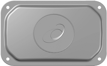 | 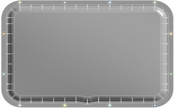 |
| Material: Aluminium alloy | Material: 30% wt GFs/PA6,6 |
| Working process: Die-casting | Working process: Injection moulding |
| 4 tightening bolts | 12 tightening studs |
| Mass: 13.3 kg | Mass: 4.8 kg |
| Property | Value | Explanation |
|---|---|---|
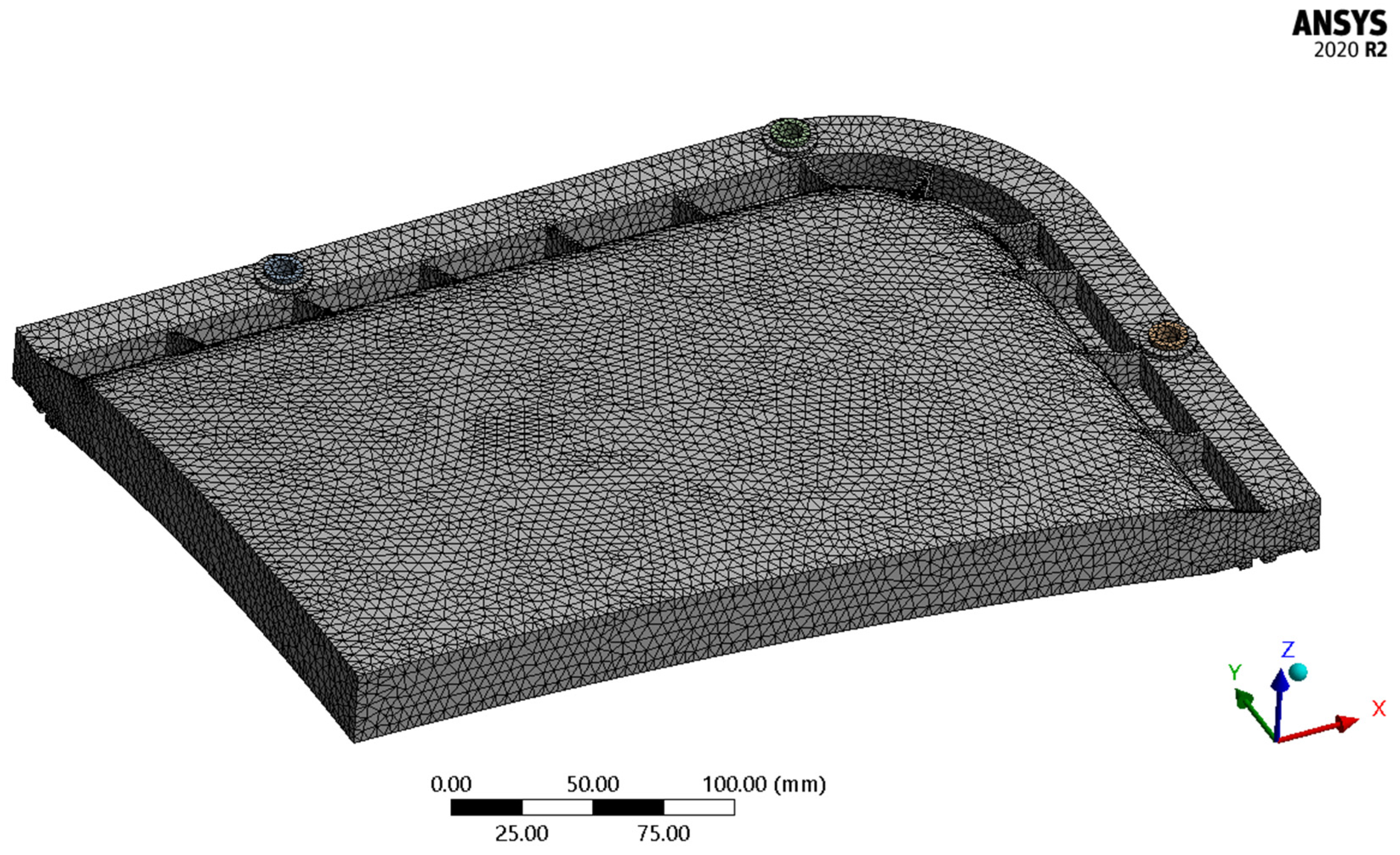
| Element size | 3 mm | - |
| Number of elements | 109,778 | - |
| Number of nodes | 201,558 | - |
| Element quality (average value) | 0.708 | Metric based on the ratio of the volume to the edge length for a given element (optimal values within 0.5 ÷ 1.0) |
| Aspect ratio (average value) | 2.361 | Ratio of longest to the shortest side in an element (optimal values within 1 ÷ 5) |
| FEA Result | Threshold Value | |
|---|---|---|
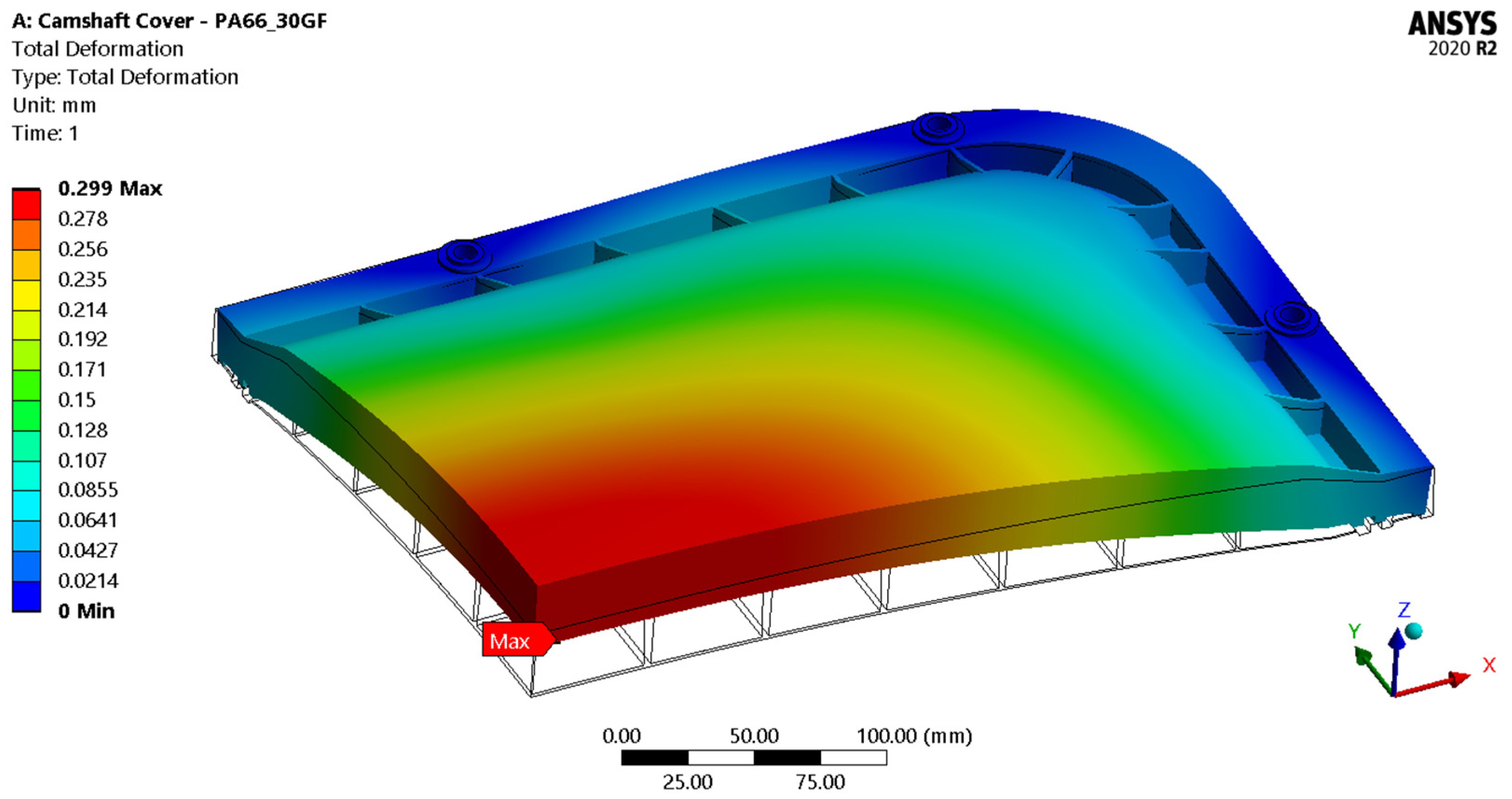
| Total deformation (mm) | 0.299 | - |
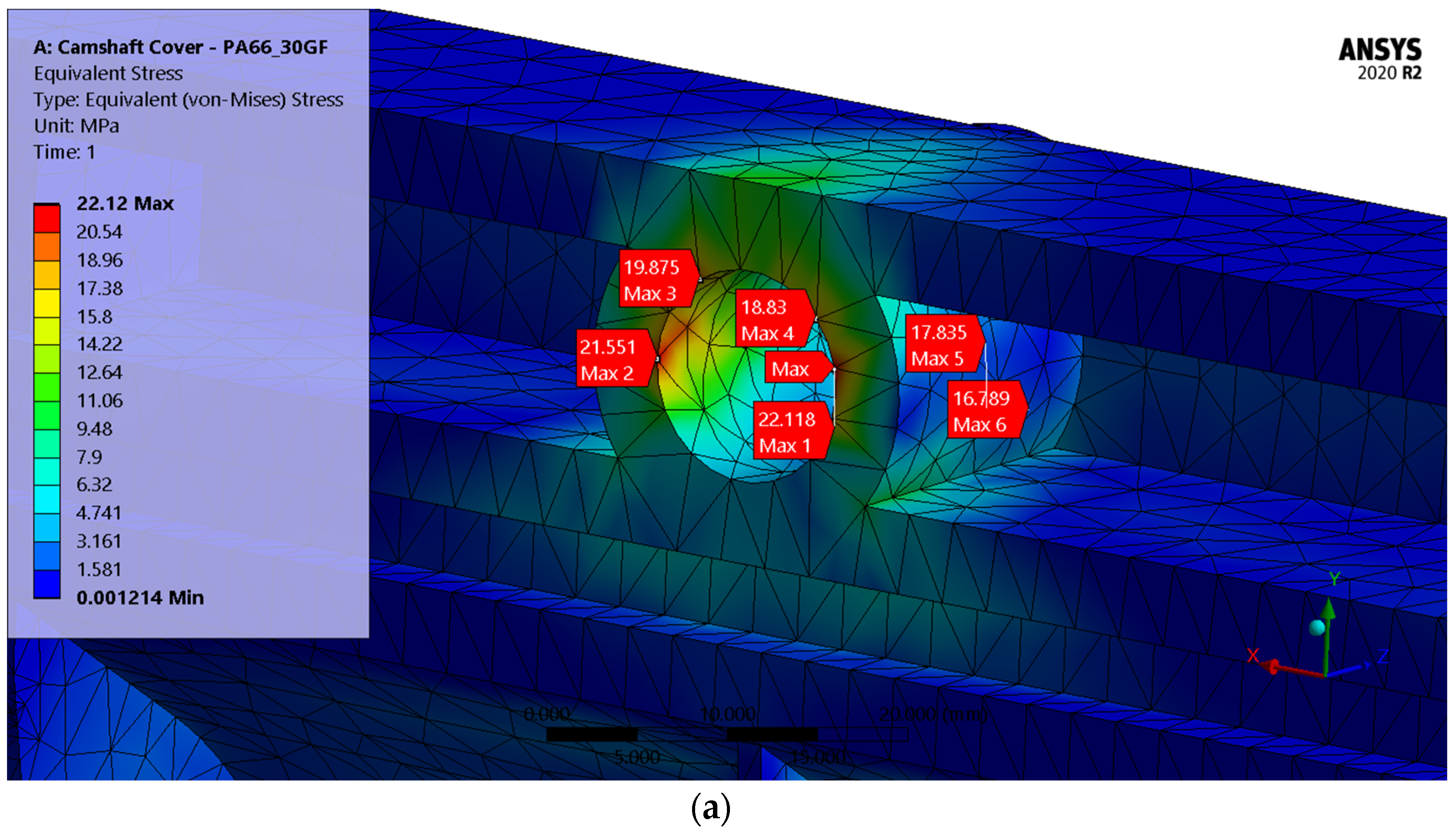
| Equivalent (von-Mises) stress (MPa) | 22.12 | 189 ± 6 |
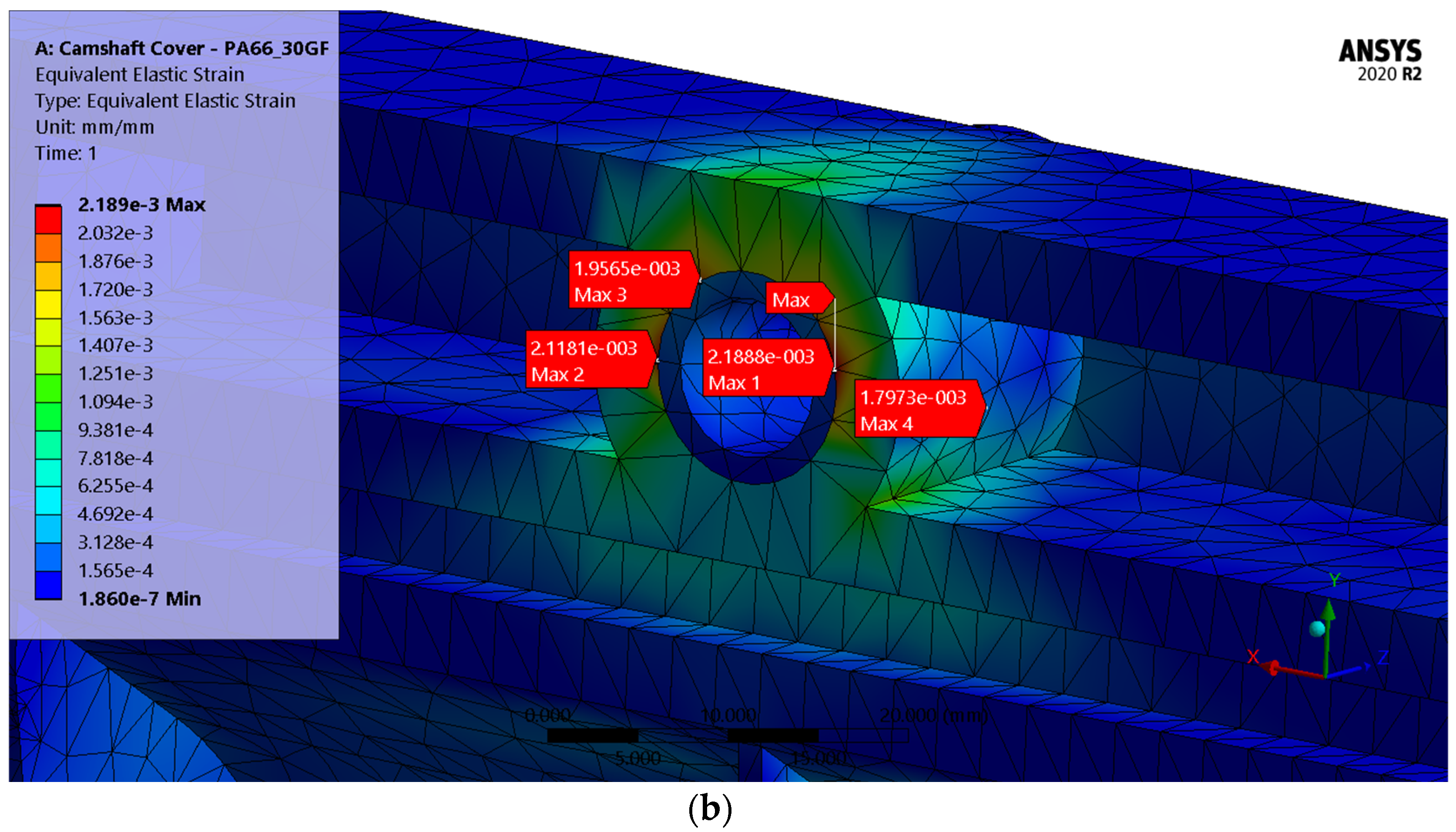
| Equivalent elastic strain (%) | 0.219 | 4 ± 0.2 |
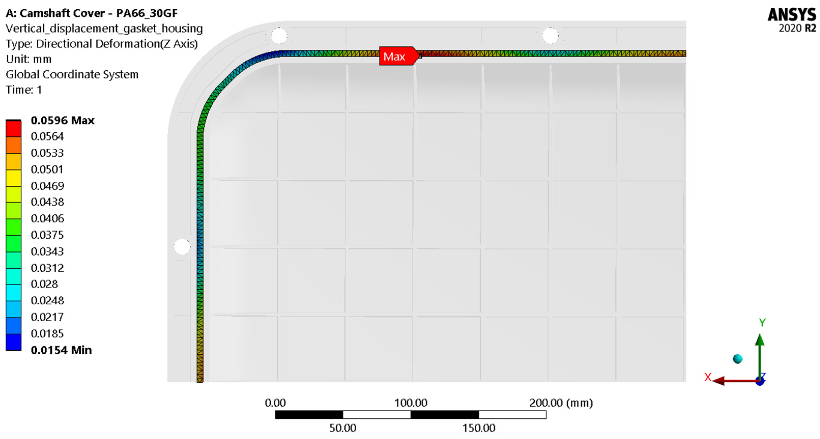
| Vertical displacement of the gasket housing (mm) | 0.0596 | - |
| Gasket compression value (%) | 28.8 | 15–30 |
Publisher’s Note: MDPI stays neutral with regard to jurisdictional claims in published maps and institutional affiliations. |
© 2022 by the authors. Licensee MDPI, Basel, Switzerland. This article is an open access article distributed under the terms and conditions of the Creative Commons Attribution (CC BY) license (https://creativecommons.org/licenses/by/4.0/).
Share and Cite
Bertagna, S.; Braidotti, L.; Laurini, E.; Marinò, A.; Pricl, S.; Bucci, V. Thermoplastic Materials for the Metal Replacement of Non-Structural Components in Marine Engines. Appl. Sci. 2022, 12, 8766. https://doi.org/10.3390/app12178766
Bertagna S, Braidotti L, Laurini E, Marinò A, Pricl S, Bucci V. Thermoplastic Materials for the Metal Replacement of Non-Structural Components in Marine Engines. Applied Sciences. 2022; 12(17):8766. https://doi.org/10.3390/app12178766
Chicago/Turabian StyleBertagna, Serena, Luca Braidotti, Erik Laurini, Alberto Marinò, Sabrina Pricl, and Vittorio Bucci. 2022. "Thermoplastic Materials for the Metal Replacement of Non-Structural Components in Marine Engines" Applied Sciences 12, no. 17: 8766. https://doi.org/10.3390/app12178766
APA StyleBertagna, S., Braidotti, L., Laurini, E., Marinò, A., Pricl, S., & Bucci, V. (2022). Thermoplastic Materials for the Metal Replacement of Non-Structural Components in Marine Engines. Applied Sciences, 12(17), 8766. https://doi.org/10.3390/app12178766