1. Introduction
Recently, derailment accidents have occurred on the double-slip turnouts of conventional railways in China, most of which occurred at the guard rail position of the acute-angle crossing and shared a similar derailment course. The double-slip turnout can help reduce the area of land used by railways, thereby improving the efficiency of shunting operations. Double-slip turnouts are slightly longer than single turnouts, and are equivalent to two sets of opposing single turnouts. In station throats with double- and multi-tracks where trains arrive, are marshaled, and depart, using double-slip turnouts with double crossovers can significantly shorten the length of the station throat. However, a double-slip turnout has a complex structure comprising two sets of acute-angle crossings, two sets of obtuse moveable point frogs, four straight-switch rails and four curved-switch rails, multiple lead rails, connecting rails, connecting parts, rail sleepers, and switch machines. Therefore, it is difficult to coordinate all these moveable parts, besides the complex wheel–track interaction when vehicles pass through [
1,
2,
3,
4].
Various domestic and international studies have focused on double-slip turnouts. Yuan and Liu [
5] improved the design of the turnout structure and rail foundation to address the problems of the No. 12 double-slip turnout for 60 kg/m rails. Liu [
6] designed and developed the No. 9 double-slip turnout for 50 kg/m rails with a 1520 mm gage, which solved the problems such as switching interference and gage expansion. Qiao et al. [
7] and Gao et al. [
8] established a longitudinal-lateral-vertical spatially coupled finite element model for double-slip turnouts, and analyzed the main mechanical characteristics and transverse deformation of the switch rail after the double-slip turnout was made seamless. He et al. [
9,
10,
11] studied the causes of typical faults with double-slip turnouts under actual operating conditions, analyzed the dynamic pattern of faults under heavy loads, and proposed corresponding remediation measures. Tian et al. [
12] and Ou et al. [
13] proposed a fault diagnosis method for double-slip turnouts based on a Bayesian network, and presented the most likely fault types. Furthermore, several studies on derailment problems have been conducted globally. Gong et al. [
14,
15] calculated and analyzed the derailment course of passenger and freight trains caused by overspeeding along curved sections. Gao et al. [
16] and Wang et al. [
17] established a spatial vibration calculation model of a vehicle–track system and analyzed the derailment course of a vehicle under a seismic effect. Ju et al. [
18] conducted vibration and derailment analyses of trains moving on curved and cant rails. Si et al. [
19] and Lai et al. [
20] studied the derailment of No. 6 symmetrical turnouts in a marshaling yard and analyzed the influence of the vehicle and turnout structure parameters on the flange climbing performance. Qiao et al. [
21] performed on-site tests to study the effect of the marshaling mode on the derailment coefficient of vehicles at the turnout of a hump yard. Yang et al. [
22] carried out an analysis on dynamic railway derailment risk with text-data-based Bayesian network. Kim et al. [
23] derived theoretical derailment equations for cross-wind with frequency to assess running safety. Zhu et al. [
24] established a vehicle dynamic model for a hump yard that comprehensively considers the hump plane and vertical sections as well as turnout characteristics, which they used to study the influence of hump track conditions on derailment. Wang et al. [
25,
26,
27] used the wheelset quasi-static derailment theory to analyze the wheel–track contact geometry when the wheelset derails at different cross sections of a turnout. They pointed out that wheel derailment at a turnout may have two flange climbing processes, and examined the safety limits of derailment of turnouts under two- and three-dimensional conditions. Yang and Dong [
28] and Li and Zhao [
29] proposed a prediction algorithm for the derailment coefficient of a turnout that combines data from multiple sensors yet did not consider enough factors to evaluate the safety of wheel–track contact. Lim et al. [
30] suggested an analysis method for a track ballast–wheel interaction that could be further developed to model the interaction in a train-derailment event, based on the discrete-element method (DEM). Zhou and Zeng [
31] studied the train derailments that occurred in China on some railway bridges due to insufficient lateral rigidity. Xiao et al. [
32] and Zhou and Shen [
33] established an asymmetric vehicle–track coupled dynamics model to analyze the influence of rail fastener failure on derailment. Song et al. [
34] conducted modeling and simulation of collision-causing derailment to design the derailment containment provision using a simplified vehicle model. Bae et al. [
35] conducted a full-scale train bogie derailment test and analyzed the post-derailment behavior of the casting bogie.
Generally, existing research on double-slip turnouts has mainly focused on structural design and fault remediation and little on derailment. The studies focusing on derailment primarily concentrate on the mechanism of derailments occurring on curved tracks, bridge sections, and switch panels of turnouts with small frog numbers, and the preventive measures to avoid the derailment. There has been little research on derailment at the crossings where guardrails are placed at a turnout, especially for double-slip turnouts.
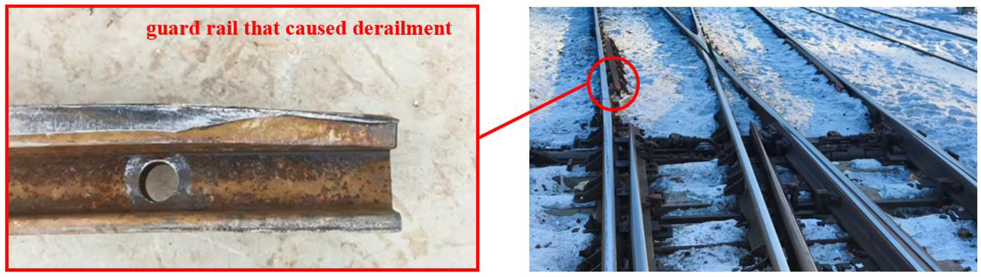
Therefore, we analyzed recent derailment accidents at double-slip turnouts in China and focused on the derailment mechanism. When a train passes through the acute-angle crossing of a double-slip turnout in the facing direction, the wheels may hit the opening section of the guardrail. Gradually, the frequent wheel impact loosens, deforms, or even damages the rail support bolt at the front end of the guardrail, which causes the rail head of the guardrail opening section to tip over to the side of the stock rail. This reduces the height difference between the stock rail and guardrail; thus, when a train passes through, the wheel flange can impact and abrade the top surface of the rail head of the guardrail opening section. The abrasion and plastic deformation eventually cause the rail head to form a stepped structure, as shown in
Figure 1. When a significant degree is reached, this stepped structure causes the wheel flange to climb the guardrail when a train passes, which eventually leads to train derailment.
Under normal operating conditions, the train wheel impacting the guardrail opening section is the direct cause of derailments at double-slip turnouts. If the wheel contact with the guardrail opening section can be prevented, the occurrence of derailment at the guardrail can be effectively reduced or avoided. According to an analysis of derailment accidents by railways bureau, the following factors lead to wheel impact on the guardrail opening section:
Track gage widening at the end of the buffer segment of the guardrail, and the flangeway not being widened by the same degree.
Abrasion at the upper rail of the curve, which increases the gage; however, the flangeway at the end of the buffer segment of the guardrail is kept the same.
During maintenance and repair, the restoring segment of gage widening of the lead curve moves backward, which increases the gage at the end of the buffer segment of the guardrail while the flangeway remains the same.
After the straight section of the guardrail experiences severe abrasion, adjusting pieces are continuously added at the end of the guardrail to maintain the check interval, which reduces the flangeway.
The guardrail bolts are not tightened in time after loosening and unloading, which causes the guardrail head to drop and reduces the flangeway.
The abovementioned scenarios can increase the guardrail interval (distance from the working edge of guardrail at the end of the buffer segment to the working edge of the rail on the opposite side) beyond the design limits and cause the wheels to hit the opening section when the train passes over the guardrail. Herein, recent double-slip turnout derailment accidents in China were analyzed to clarify the derailment mechanism. A large field study was conducted to explore the causes of wheel impact on the opening section of the guardrail. Some of the impacts are due to long-term abrasion or improper maintenance and repair, which can be effectively avoided through proper remediation and maintenance. However, some wheel impact scenarios cannot be effectively avoided regardless of the maintenance; these scenarios mainly occur with double-slip turnouts and occasionally with single turnouts. An in-depth analysis was conducted on the structural characteristics of the turnout and the wheel–track relationship for impacts in the opening section of the guardrail when maintenance requirements are met. The objective was to explore the reasonableness of the current calculation method for the guardrail interval limit and to establish an improved version.
2. Limitations of the Existing Calculation Method for the Guardrail Interval Limit
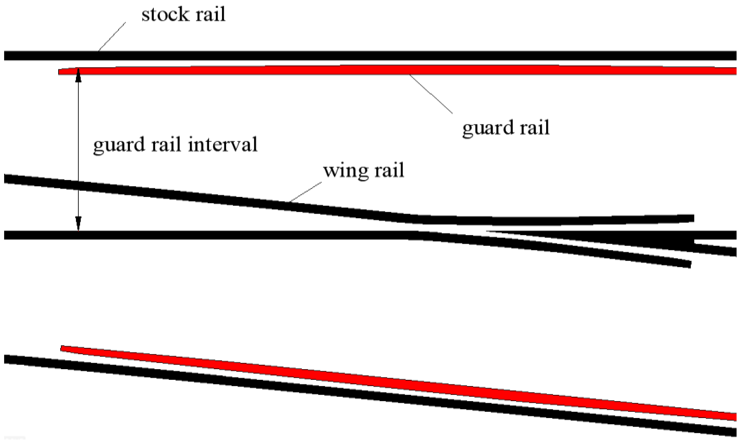
The concept of a guardrail interval is proposed based on the European Standard (EN) [
36] and can be defined as the distance from the working edge of the end of the buffer segment of a guardrail to the working edge of the rail on the opposite side, as shown in
Figure 2.
The guardrail interval limit should be set to ensure that various types of trains can smoothly pass through the guardrail opening section without collision, as shown in
Figure 3. The guardrail interval limit can be calculated using Equation (1):
where
is the minimum wheelset inner distance (i.e., 1350 mm),
is the wheelset inner distance reduction under the vehicle load (i.e., 2 mm), and
is the minimum flange thickness (i.e., 22 mm). With these assumed values, the guardrail interval
should be less than 1370 mm. In the worst-case scenario, where the most adverse wheelset has its edge against the rail, this limit ensures that the wheel back on the other side will not touch the guardrail.
A statistical analysis of the field data showed that none of the various turnout types resulted in a wheel–track impact in the opening section at the toe or heel end of the straight guardrail and the opening section at the heel end of the lateral guardrail. Wheel–track impact only occurred in the opening section at the toe end of the lateral guardrail. When a train passes through a turnout in trailing and straight-facing directions, it runs in a straight line before entering the guardrail. Only when a train passes through the turnout in the side-facing direction does it run along a curve before entering the guardrail. Therefore, when a train is running in a straight line before entering the guardrail, the current guardrail interval limit should ensure that the wheels will not hit the opening section of the guardrail. However, when the train is running along a curve before entering the guardrail, the current guardrail interval limit does not completely avoid a wheel–track impact at the opening section.
The existing calculation method also does not consider the impact based on the vehicle running attitude and the wheelset angle of attack. Therefore, the worst-case conditions are not considered. When the vehicle crosses the turnout in a straight line, the wheel running direction is parallel to the rail, which ensures that the back of the wheel does not hit the opening section of the guardrail, as shown in
Figure 4a. When the vehicle crosses the turnout in the side-facing direction, the wheels are barely out of the lead curve or are still in the lead curve before entering the toe end of the guardrail. The bogie approaches or reaches the free inscribing state when running on a small-radius curve, and the wheel running direction and rail direction are at different angles. Under the worst-case condition, when a guiding wheelset with the smallest inner distance and thinnest flange enters the opening section of the guardrail, the wheels on the upper rail of the curve are in immediate contact with the rail, and the wheels on the lower rail of the curve are far from the rail. The twisting of the bogie and wheelset moves the lower wheels further from the rail, which causes the distance between the back of the lower wheel and the working edge of the upper rail to drop below the guardrail interval limit of 1370 mm. This causes a collision with the guardrail opening section, as shown in
Figure 4b.
Therefore, to prevent the wheels from hitting the opening section of the guardrail when the vehicle crosses the turnout in the side-facing direction, the vehicle running attitude and the wheelset angle of attack need to be considered for the guardrail interval limit.
3. Proposed Calculation Method of the Guardrail Interval Limit Based on the Vehicle Running Attitude
The guardrail interval limit ensures that the wheels of a vehicle do not hit the opening section when it enters the guardrail section. Actually, the existing calculation method is a one-dimensional model, which does not consider the influence of the vehicle running attitude and wheelset angle of attack, and thus cannot account for the worst-case conditions. The actual worst-case conditions are as follows: when the bogie with the worst-case parameters passes the turnout in the side-facing direction, it enters the opening section at the toe end of the guardrail in the free inscribing state. In view of this, a two dimensional model is developed in this section to calculate the guardrail interval limit, which can consider the worst-case conditions.
First, the most adverse bogie parameters were studied. The existing calculation method for the guardrail interval limit indicates that a small wheel flange thickness and wheelset inner distance increase the likelihood that the wheel hits the guardrail. Therefore, the wheel flange thickness d and wheelset inner distance T were still set to the minimum values of 22 and 1350 mm, respectively. The possible reduction of the wheelset inner distance due to the vehicle load was considered, and it was set to a value of 2 mm. When a vehicle is running in the lead curve section, decreasing the bogie axis distance increases the angle of twisting when it reaches the free inscribing state, and the wheel becomes more likely to hit the guardrail. Therefore, the bogie axis distance Q was set to the minimum value of 1.8 m, which matches the actual dimensions of railway tracks.
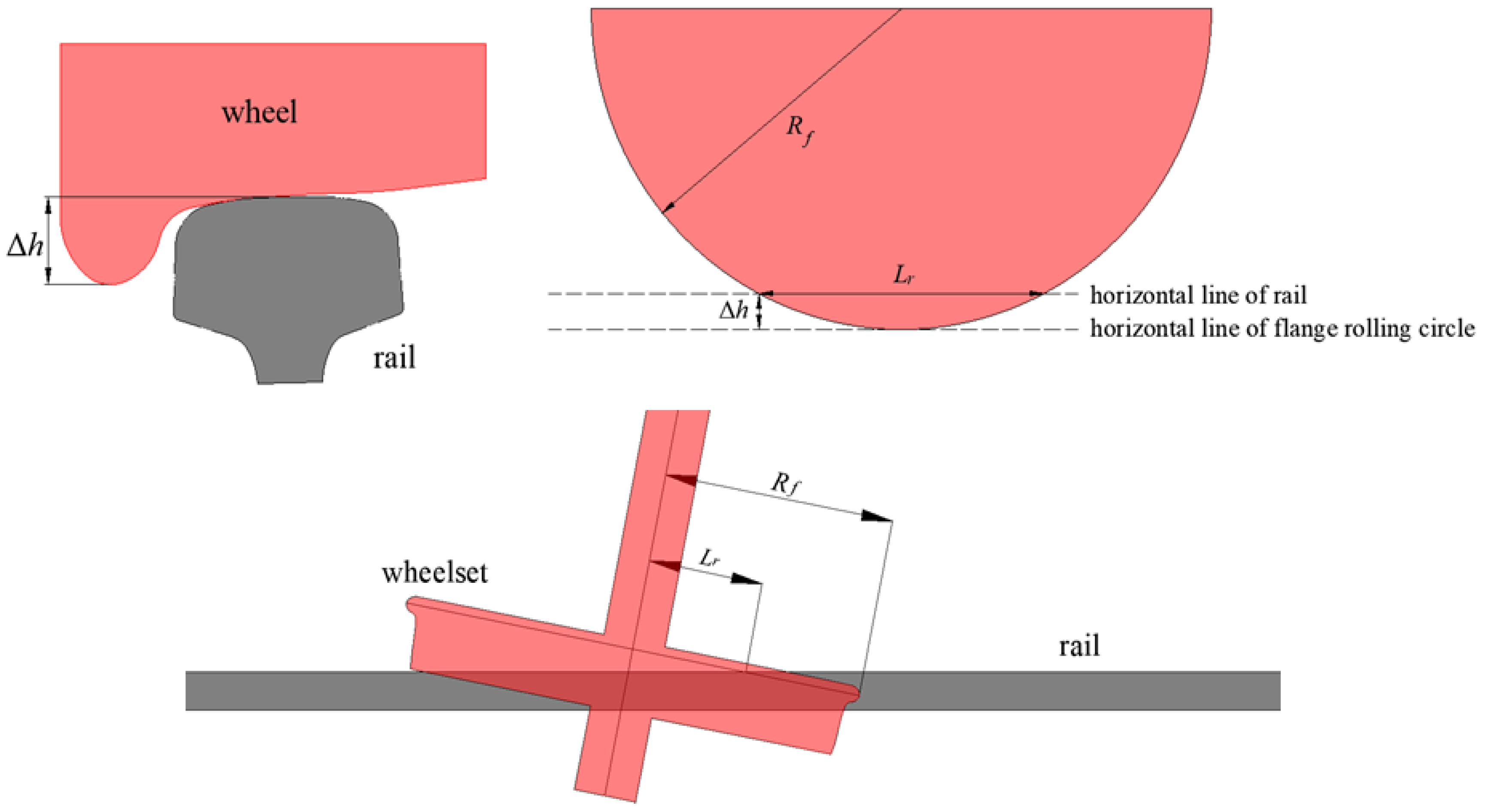
In the free inscribing state, the front wheelset flange of the bogie is in contact with the upper rail of the curve, while the rear wheelset flange is in contact with the lower rail of the curve. The radius of the wheel flange rolling circle
and the height difference between the top of the wheel flange and top surface of the rail
determine the twisting angle of the bogie in the free inscribing state, as shown in
Figure 5. A small
and
decrease the length of the secant line between the flange rolling circle and the top surface of the rail
, which weakens the ability of the rail to limit the twisting of the wheelset and increases the twisting angle of the bogie in the free inscribing state. Therefore, the minimum value of
can be calculated using Equation (2):
where
is the minimum value of
,
is the minimum value of the nominal rolling circle radius of the wheel (i.e., 420 mm), and
is the minimum value of the wheel flange height (i.e., 27 mm). Therefore,
is 447 mm.
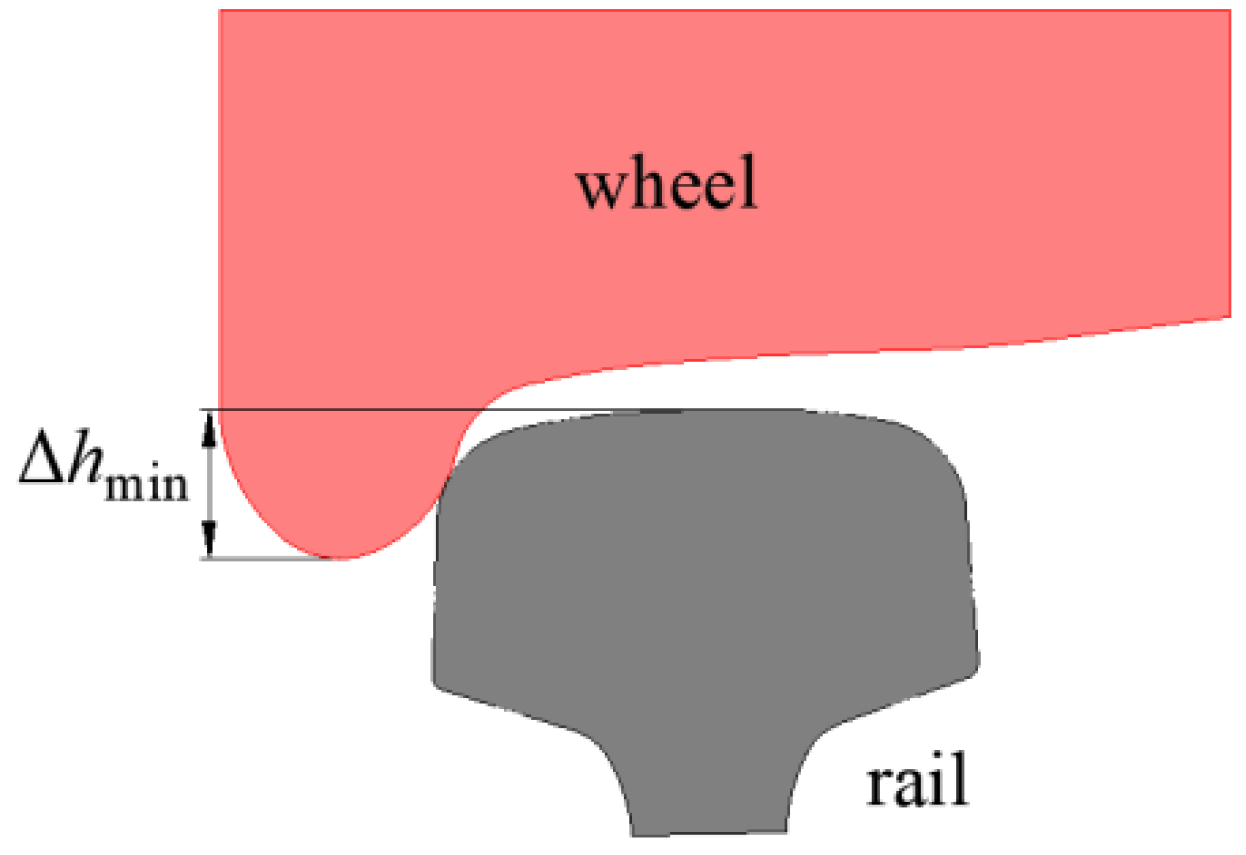
When a vehicle passes through a small-radius curve at a high speed, the bogie may experience a slight flange climb due to centrifugal forces after reaching the free inscribing state, as shown in
Figure 6. This will further reduce the height difference between the top of the wheel flange and the top surface of the rail
and further increase the twisting angle of the bogie, which is defined as the extreme inscribing state. In this case, the minimum value of
should be calculated using Equation (3) to consider the slight flange climb of the wheels in the extreme inscribing state.
where
is the minimum value of
and
is the flange climb of the wheel in the extreme inscribing state, which can be set to 12 mm. Then,
is 15 mm.
According to the above parameters, when the bogie reaches the maximum twisting angle, the probability of the flange of the lower wheel of the curve hitting the guardrail is closely related to the height difference between the top of the flange and the top surface of the guardrail
, as shown in
Figure 7. A larger value of
will cause a longer length of the secant line between the lower wheel flange rolling circle and the top surface of the guardrail
and reduce the distance from the endpoint of the secant line to the working edge of the upper rail of the curve, which increases the probability that the flange hits the guardrail. In this case, the maximum value of
is calculated using Equation (4).
where
is the maximum value of
and
is the height difference from the top surface of guardrail to the top surface of stock rail, which can be set to 12 mm based on the main types of turnouts in China. Then,
is 39 mm.
Based on the abovementioned parameters, the length of the secant line between the wheel flange rolling circle and top surfaces of the rail and guardrail under the worst-case conditions can be calculated using Equation (5).
where
is the minimum length of the secant line between the wheel flange rolling circle and the top surface of the rail (i.e., 230 mm) and
is the maximum length of the secant line between the wheel flange rolling circle and the top surface of the guardrail (i.e., 365 mm).
Based on the above analysis,
Figure 8 shows a bogie model under the worst-case conditions. Because the radius of the lead curve, gage-widening segment, and other alignment parameters vary among different types of turnouts, the worst-case attitude also differs for a bogie entering the guardrail opening section, which affects the guardrail interval limit. Based on the established worst-case bogie model and specific parameters for the turnout alignment, the inscribing state can be constructed based on the length of the secant line
of flange rolling circles of the upper wheel of the front wheelset and the lower wheel of the rear wheelset. In the inscribing state, when the front wheelset of the bogie is at the end of the buffer segment at the toe end of the guardrail, then the vertical distance from the end of the secant line
of the lower wheel flange rolling circle to the working edge of the upper rail of the curve is the necessary guardrail interval limit. This is shown in
Figure 9.
4. Validation of the Proposed Calculation Method
The No. 9 double-slip turnout for 60 kg/m rail, which has experienced derailment at the guardrail, was taken as an example to verify the reasonableness of the proposed calculation method. The number of design drawing for the double-slip turnout is SC450, which has a lead curve radius of 220 m, gage widening of 15 mm, angle of attack of 1°20′10″ for the tip of the switch rail and distance of 1751 mm from the tip of the switch rail to the end of the buffer segment of the guardrail. The end of the gage-widening segment extends to the guardrail, whose distance to the end of the buffer segment is 999 mm.
The proposed calculation was used to calculate the guardrail interval limit for the acute-angle crossing of the double-slip turnout, as shown in
Figure 10. The calculated limit was 1365.82 mm. However, the existing calculation method used by the railway maintenance department sets the limit to 1370 mm. Therefore, normal vehicle passage cannot be guaranteed; there is wear and impact at the opening section of the guardrail, which eventually leads to further derailment.
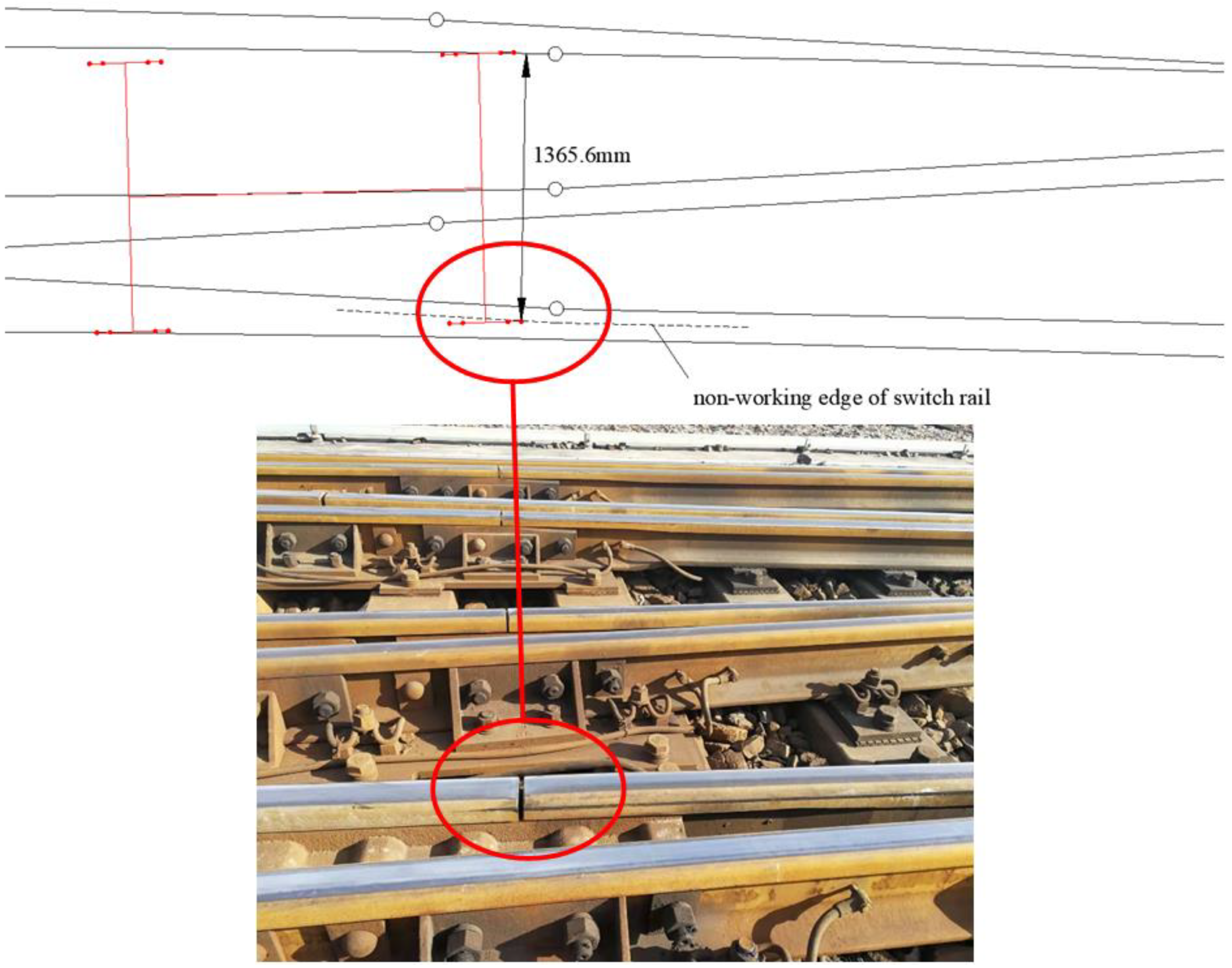
Wheel–track interactions in the double switch area are similar to those in the acute-angle crossing area for double-slip turnout. When the distance between the nonworking edge of the switch rail and the working edge of the opposite rail is too large, wheel–track interactions cause impact and wear on the nonworking edge of the switch rail. Furthermore, the bogie approaches or reaches the inscribing state because in the curved section the twisting angle is relatively large. Therefore, the proposed method was used to calculate the interval limit for the switch rail nonworking edge (i.e., distance from the nonworking edge of the switch rail to the working edge of the opposite rail) when a vehicle passes through the double switch area (
Figure 11). The limit was calculated to be 1365.6 mm. Then, the minimum flangeway of the switch rail (i.e., minimum distance between the nonworking edge of the switch rail and the working edge of the stock rail) can be calculated using Equation (6).
where
is the minimum flangeway of the switch rail,
is the track gage (i.e., 1450 mm), and
is the interval limit for the switch rail nonworking edge (i.e., 1365.6 mm). Thus,
is 84.4 mm.
According to the design requirements of the SC450 turnout, the minimum flangeway of the switch rail in the double switch area is set to 80 mm by the railway maintenance department. Thus, it also cannot ensure normal vehicle passage. The nonworking edge of the switch rail will also have wheel–track impact. Field tests showed that the nonworking edge of the switch rail for this turnout experiences wheel–rail impact and wear. Additionally, the flangeway of the switch rail corresponding to the starting position of wear traces (i.e., where the wheel started to contact the nonworking edge of the switch rail) happened to be 84 mm, which is consistent with the calculation results herein. Therefore, the feasibility of the proposed calculation method was verified.
5. Guardrail Interval Limits for Main Turnout Types and Analysis of Influencing Factors
Considering the influence of the vehicle running attitude, different turnouts require different guardrail interval limits. However, to facilitate field maintenance, a unified limit needs to be set that is applicable to all types of turnouts. To establish a reasonable guardrail interval limit that meets the needs of most types of turnouts and reduces the wheel–track impact and abrasion in the opening section, the proposed calculation method was used to determine the limits for single turnouts and double-slip turnouts widely used by major railways in China. The calculation results are presented in
Table 1 and
Table 2.
The calculated guardrail interval limits were distributed between 1365 and 1367 mm. For single turnouts, the No. 9 single turnout for 50 kg/m rail (Design Drawing No. CZ2209) required the smallest guardrail interval limit of 1365.48 mm, and the No. 18 single turnout for 50 kg/m rail (Design Drawing No. ZX 4275) required the largest guardrail interval limit of 1366.98 mm. For double-slip turnouts, the No. 9 double-slip turnout for 50 kg/m rail (Design Drawing No. CZ2214) required the smallest guardrail interval limit of 1365.52 mm, and the No. 12 double-slip turnout for 60 kg/m rail (Design Drawing No. SC350) required the largest guardrail interval limit of 1366.64 mm. For actual maintenance and repair, the guardrail interval limit should be 1365 mm, which will meet the needs of most turnouts and effectively avoid the occurrence of wheel–track impact in the opening section of guardrail and prevent derailment accidents.
The calculation results showed a strong correlation between the guardrail interval limit and turnout alignment parameters.
Figure 12 and
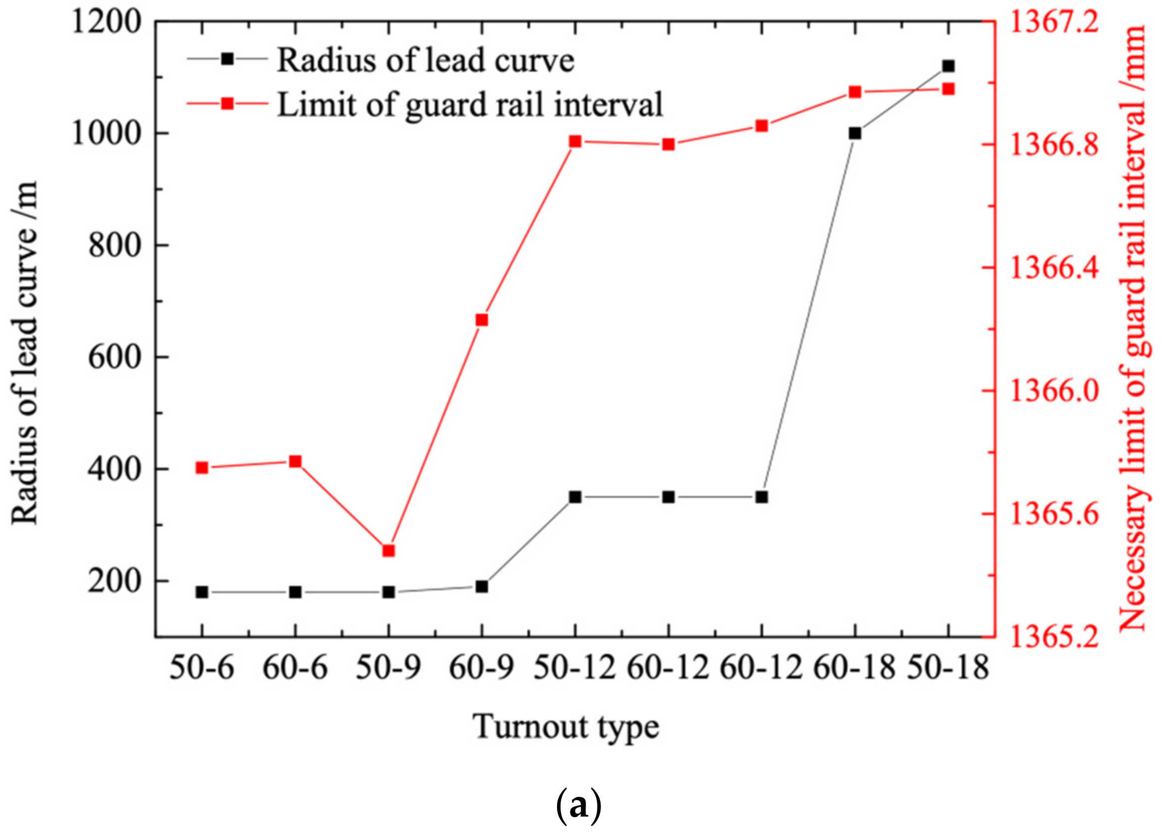
Figure 13 show the influence of different alignment parameters on the guardrail interval limits of single turnouts and double-slip turnouts, respectively.
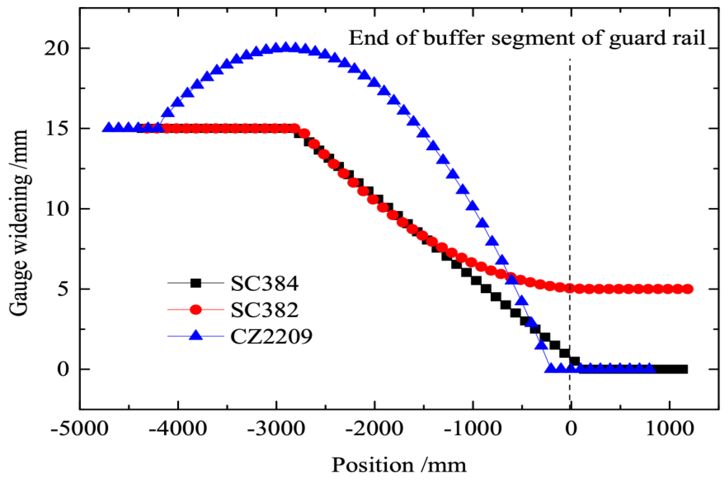
For single turnouts, reducing the frog number and radius of the lead curve and increasing the gage widening generally decreased the guardrail interval limit. However, the No. 9 single turnout for 50 kg/m rail (Drawing No. CZ2209) required a smaller guardrail interval limit than the No. 6 symmetrical turnouts even though the radius of the lead curve and that of the gage widening were identical, and the ends of the lead curve and gage-widening segment were located near the end of the buffer segment of the guardrail. However, the lower rails in the restoring segment of gage-widening of the No. 6 symmetrical turnout for 50 kg/m rail (Drawing No. SC384) and No. 6 symmetrical turnout for 60 kg/m rail (Drawing No. SC382) adopted a curved-track design, while the lower rail in the restoring segment of gage-widening of the No. 9 single turnout for 50 kg/m rail (Drawing No. CZ2209) adopted a straight-track design.
Figure 14 shows the variation law of gage in the restoring segment of gage-widening of the three turnouts. The CZ2209 turnout had a large gage in the gage widening restoring segment with a maximum widening of close to 20 mm just in front of the toe end of the guardrail. This leads to an increased twisting angle when the bogie entered the guardrail, decreasing the guardrail interval limit.
Figure 12 shows that the guardrail interval limit decreased as the lead curve endpoint and gage-widening endpoint converged to the toe end of the buffer segment of the guardrail. When the gage-widening endpoint reached or entered the buffer segment, the adverse effects continued to aggravate. However, when the lead curve endpoint reached or entered the buffer segment, the adverse effects did not aggravate. Seven types of small-number single turnouts had the end of the lead curve very close to the end of the buffer segment of the guardrail, and two types of No. 18 turnouts had the endpoints of the lead curve deep into the crossing area and the buffer segment inside the lead curve. However, compared with turnouts with small frog numbers, which had their endpoints of the lead curve already near the end of the buffer segment, the two types of No. 18 turnouts did not evidence more adverse effects.
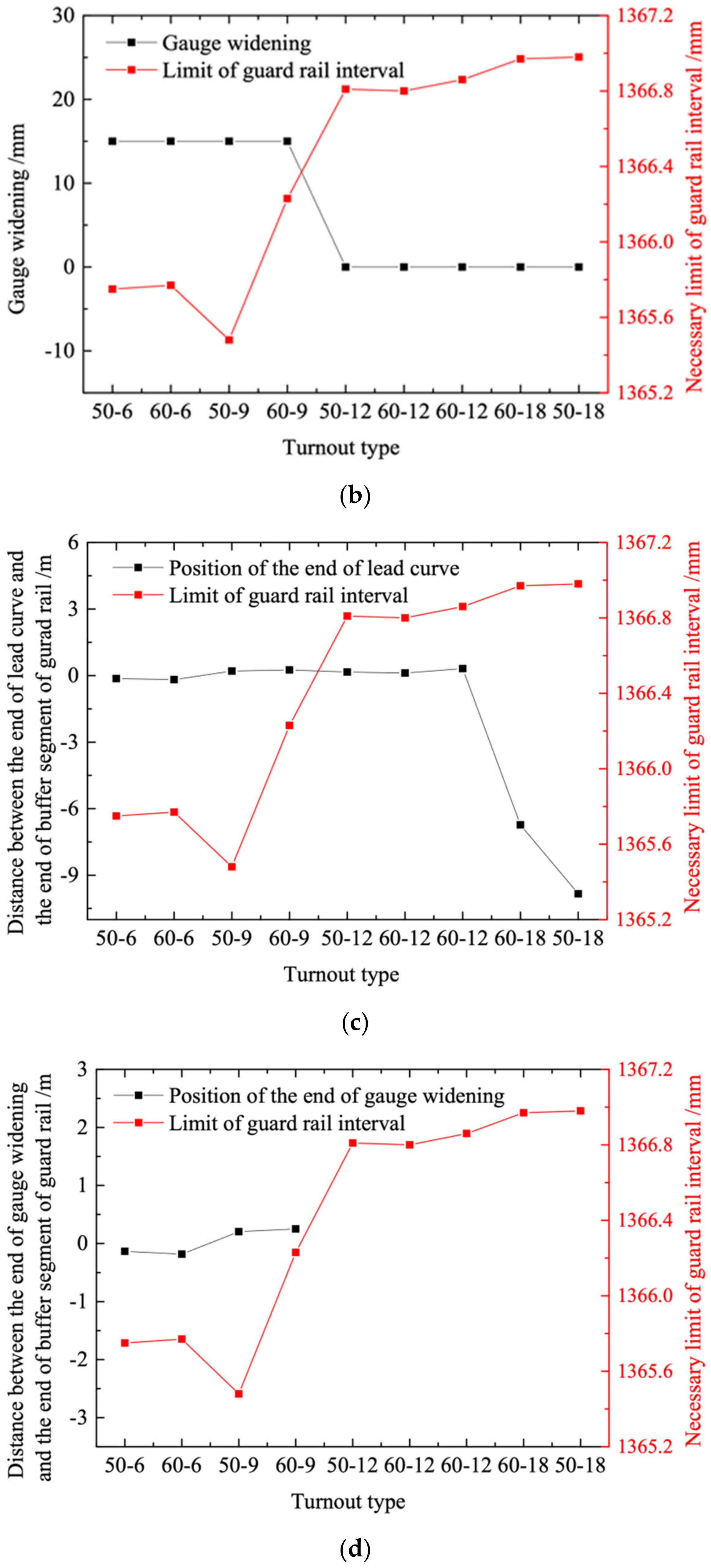
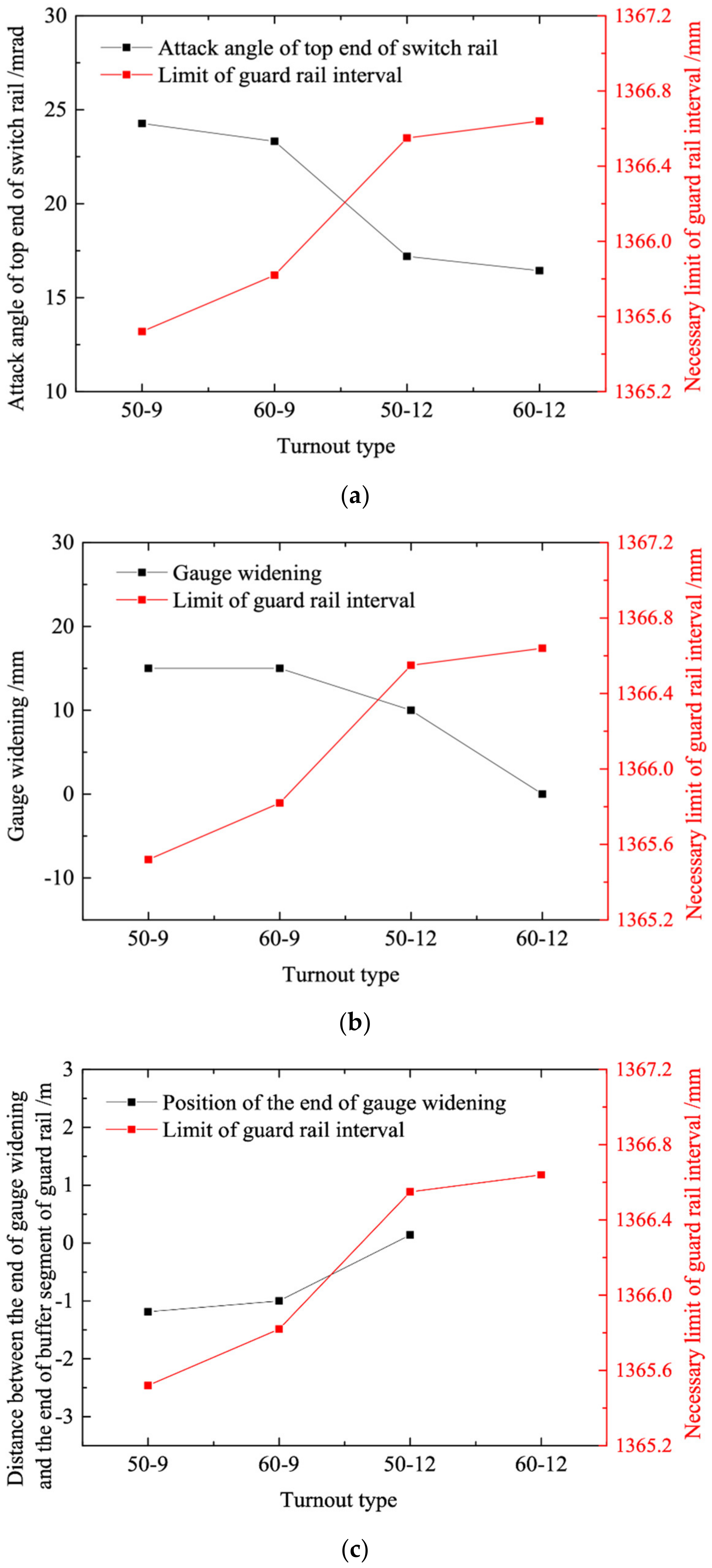
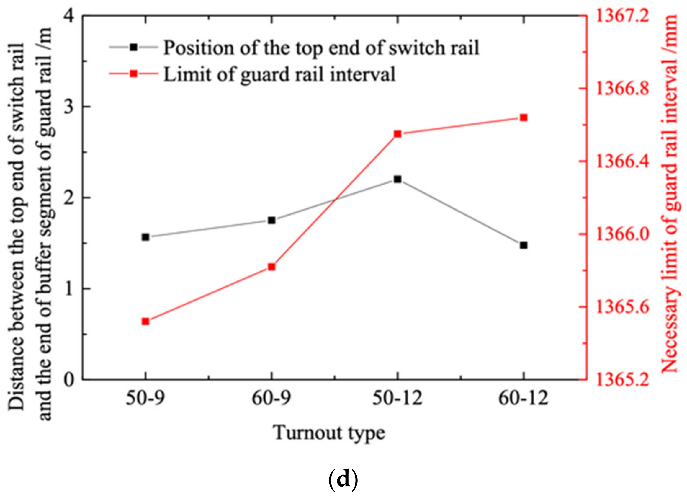
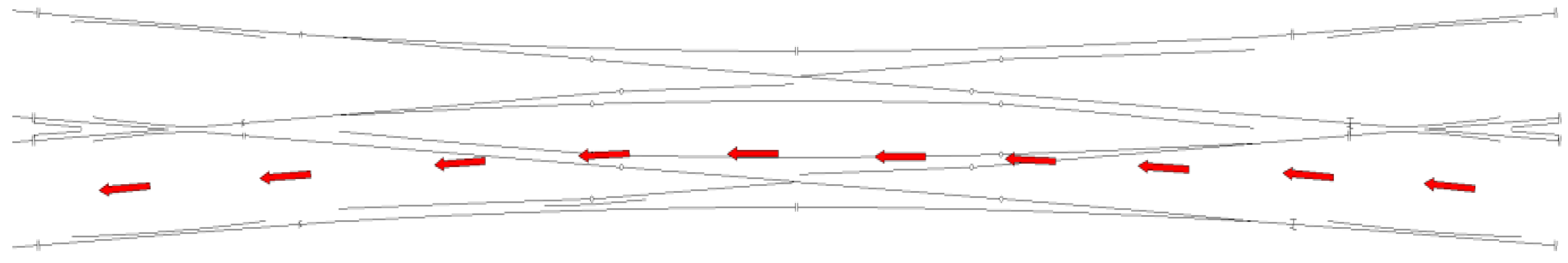
For double-slip turnouts, decreasing the frog number and increasing the angle of attack at the tip of the switch rail and the gage widening decreased the guardrail interval limit. A vehicle is most likely to hit the opening section of the guardrail when it passes the side-in and side-out paths of the double-slip turnout, as shown in
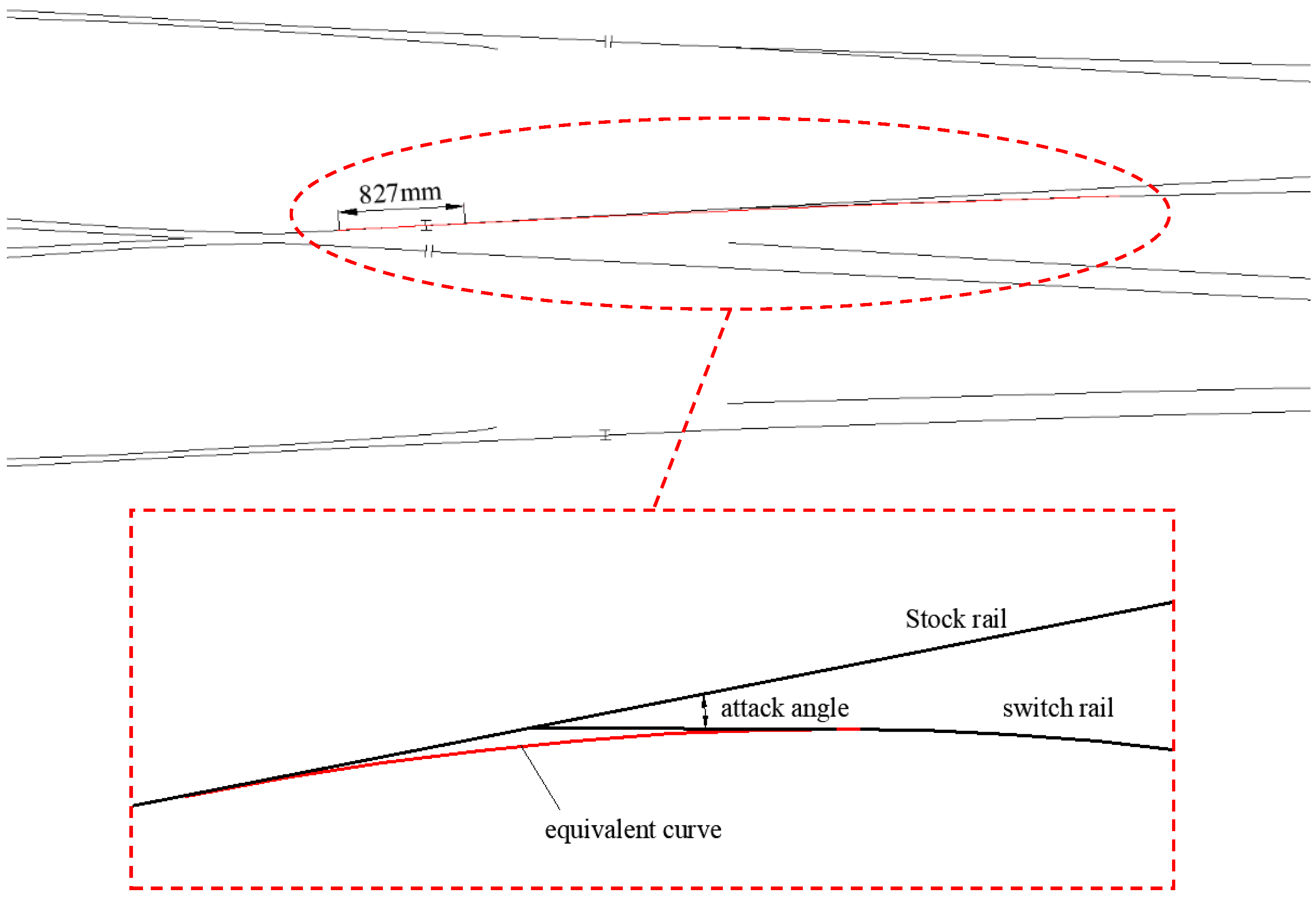
Figure 15. Under these conditions, the vehicle enters the straight segment in the front of the switch rail from the lead curve segment and then enters the stock rail in front of the switch rail through wheel load transition before finally entering the guardrail. Although the lead curve is relatively far from the guardrail, the angle of attack at the tip of switch rail means that the bogie still approaches or reaches the inscribing state before it reaches the toe end of the guardrail despite not running on the curved track. This is because it runs on a broken rail comprising the switch rail and stock rail. The twisting effect produced by the broken rail is not inferior to that produced by a curved track. For example, the No. 9 double-slip turnout for 60 kg/m rail has a distance of 1751.36 mm from the tip of the switch rail to the end of the buffer segment of the guardrail. The angle of attack at the tip of the switch rail is 1°20′10″, and the radius of the lead curve is 220 m. Before it enters the guardrail, the bogie passes through a broken rail comprising the switch rail and stock rail.
Figure 16 shows an inscribed circle of this broken rail based on the radius of the lead curve. The endpoint of the equivalent curve of the broken rail extends into the guardrail, and the distance from the end of the curve to the end of the buffer segment of the guardrail is 827 mm.
As shown in
Figure 13c, the guardrail interval limit can be reduced by decreasing the distance between the tip of the switch rail and the buffer segment at the toe of the guardrail. However, although this distance was relatively small for the No. 12 double-slip turnout for the 60 kg/m rail (Drawing No. SC350), the guardrail interval limit was still relatively large because of the small angle of attack at the tip of the switch rail and the absence of gage widening.
Figure 13d shows that the guardrail interval limit can be reduced by decreasing the distance between the endpoint of the gage widening and the buffer segment at the toe of the guardrail. When the endpoint of the gage widening reaches or enters the end of the buffer segment, the adverse effects continue to aggravate.
6. Summary
To address the derailment problem in recent years at the guardrail of the double-slip turnouts, this study focused on clarifying the derailment mechanism and discussed the feasibility of both the existing guardrail interval limit and its calculation method. A calculation method for the guardrail interval limit was proposed that considers the vehicle running attitude and wheelset angle of attack. It was verified against the actual measurement data of double-slip turnouts where derailment occurred. The proposed calculation method was used to determine the guardrail interval limits of the main types of single turnouts and double-slip turnouts in China and to analyze the main influencing factors and laws. The main conclusions are as follows.
(1) Under the most unfavorable vehicle conditions, the turnout alignment determines the guardrail interval limit. According to the calculated results using the developed method, the guardrail interval limit should be 1365 mm, which meets the requirements of most turnouts and effectively avoids impact and wear as well as derailment at the opening section of the guardrail.
(2) For single turnouts, the guardrail interval limit can be reduced by decreasing the frog number and the radius of the lead curve and gage widening. The guardrail interval limit can also be reduced by decreasing the distance from the end of the lead curve and the end of the gage widening to the buffer segment at the toe end of the guardrail. When the endpoint of the gage widening reaches or is deep into the end of the buffer segment, the adverse effects are aggravated. When the end of the lead curve reaches or enters the end of the buffer segment, adverse effects do not worsen. In the gage widening restoring segment, a straight-track design is more likely to increase the twisting angle of the bogie than a curved-track design, which will reduce the guardrail interval limit.
(3) For double-slip turnouts, the guardrail interval limit can become smaller with the decrease of the frog number and the increase of the gage widening. A broken rail comprising the stock rail and switch rail in front of the guardrail will cause the bogie to approach or reach the inscribing state, which will cause adverse effects similar to those of a curved rail. The guardrail interval limit can decrease with the increase of the angle of attack at the tip of the switch rail, and the reduction in the distance from the tip of the switch rail and end of the gage widening to the buffer segment at the toe end of the guardrail. When the end of the gage widening reaches or enters the end of the buffer segment, the adverse effects continue to increase.
In future, more field test data will be used to verify the method for calculating guardrail interval limits proposed in this paper as well as the feasibility of the recommended guardrail interval limit. This verified interval limit will effectively avoid wheel–rail impact and derailment at the opening section of the guardrail in turnout, thereby ensuring vehicle safety. Further, the optimization design of turnout will be conducted based on the results obtained in this research.


