
Application of Unconstrained Cobalt and Aluminium Metal Powders in the Alloying of Carbon Steel in Submerged Arc Welding: Thermodynamic Analysis of Gas Reactions


Abstract
:1. Introduction
2. Materials and Methods
2.1. Welding Tests
2.2. Materials and Analyses
2.3. Thermochemical Calculations
3. Results
3.1. Chemical Analyses
3.2. Mass Balance
4. Discussion
5. Conclusions
- The application of unconstrained cobalt and aluminium powders in SAW was used to alloy carbon steel weld metal to 5.3% Co and 4.2% Al. These alloying numbers were translated by mass balance to calculate yield numbers to the weld metal of 70% for Co and 55% for Al.
- Sufficient control of the oxygen potential at the slag–weld pool interface was achieved by the application of aluminium powder. This was done without interfering with oxygen transfer from the arc plasma to the weld pool. The total weld metal oxygen content was controlled to 230 ppm O in MP7 weld metal vs. 499 ppm O in the base case wled metal when no metal powder was added.
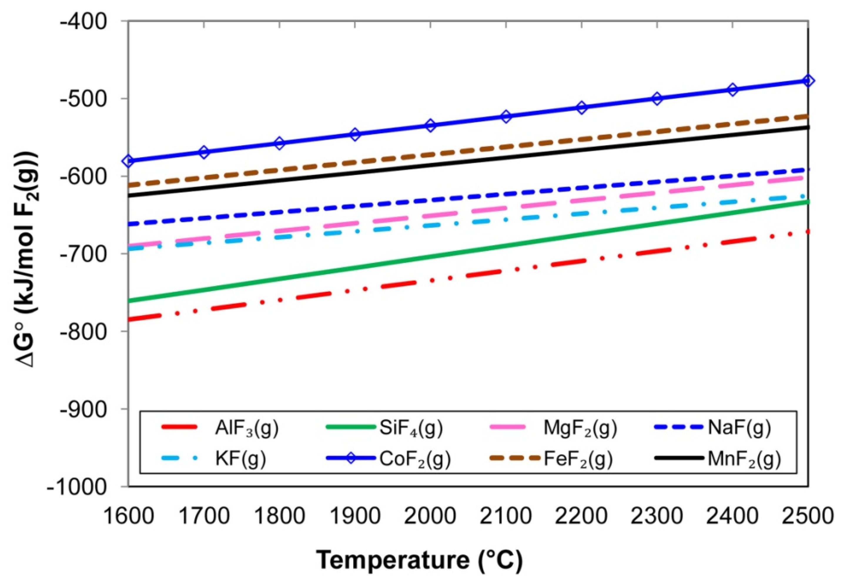
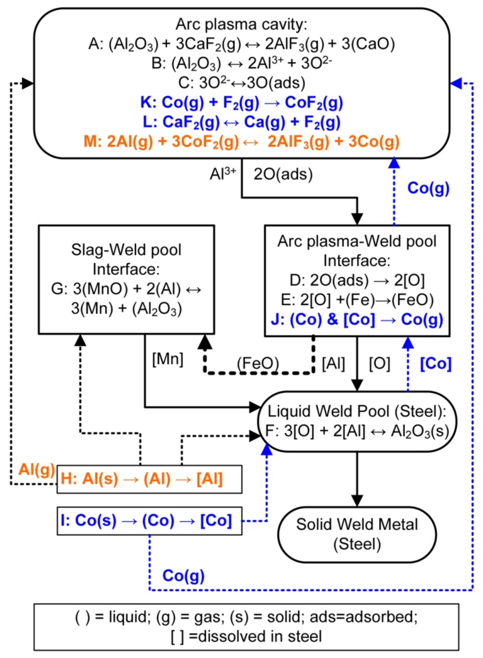
- Gas–slag–metal powder equilibrium calculations show that increased Co vapour formation is favoured by increased addition of Al powder to the reaction system, because aluminium fluorides are thermodynamically favoured ahead of CoF2(g) at the high temperatures in the arc cavity (2500 °C).
- The application of unconstrained metal powders in SAW improves the overall welding process productivity. Expensive time-consuming steps, namely manufacturing of alloyed wire and alloyed powder, can be eliminated if unconstrained metal powders are applied directly in the SAW process.
Author Contributions
Funding
Data Availability Statement
Conflicts of Interest
References
- Sengupta, V.; Havrylov, D.; Mendex, P.F. Physical phenomena in the weld zone of submerged arc welding—A Review. Weld. J. 2019, 98, 283–313. [Google Scholar]
- O’Brien, A. Welding Handbook—Materials and Applications, Part 1, 9th ed.; American Welding Society (AWS): Miami, FL, USA, 2011; Volume 4. [Google Scholar]
- Dallam, C.B.; Liu, S.; Olson, D.L. Flux composition dependence of microstructure and toughness of submerged arc HSLA weldments. Weld. J. 1985, 64, 140–152. [Google Scholar]
- Polar, A.; Indacochea, J.E.; Blander, M. Electrochemically generated oxygen contamination in submerged arc welding. Weld. J. 1990, 69, 68–74. [Google Scholar]
- Lau, T.; Weatherly, G.C.; Mc Lean, A. The sources of oxygen and nitrogen contamination in submerged arc welding using CaO-Al2O3 based fluxes. Weld. J. 1985, 64, 343–347. [Google Scholar]
- Eagar, T.W. Sources of weld metal oxygen contamination during submerged arc welding. Weld. J. 1978, 57, 76–80. [Google Scholar]
- Chai, C.S.; Eagar, T.W. Slag metal reactions in binary CaF2-metal oxide welding fluxes. Weld. J. 1982, 61, 229–232. [Google Scholar]
- Tuliani, S.S.; Boniszewski, T.; Eaton, N.F. Notch toughness of commercial submerged arc weld metal. Weld. Met. Fabr. 1969, 37, 327–339. [Google Scholar]
- Chai, C.S.; Eagar, T.W. Slag-metal equilibrium during submerged arc welding. Metall. Trans. B 1981, 12, 539–547. [Google Scholar] [CrossRef]
- Mitra, U.; Eagar, T.W. Slag-metal reactions during welding: Part I. Evaluation and reassessment of existing theories. Metall. Trans. B 1991, 22, 65–71. [Google Scholar] [CrossRef]
- Palm, J.H. How fluxes determine the metallurgical properties of Submerged Arc Welds. Weld. J. 1972, 51, 358–360. [Google Scholar]
- Paniagua-Mercado, A.M.; Lopez-Hirata, V.M.; Saucedo Munoz, M.L. Influence of the chemical composition of flux on the microstructure and tensile properties of submerged-arc welds. J. Mater. Proc. Technol. 2005, 169, 346–351. [Google Scholar] [CrossRef]
- Bang, K.; Park, C.; Jung, H.; Lee, J. Effects of flux composition on the element transfer and mechanical properties of weld metal in submerged arc welding. J. Met. Mater. Int. 2009, 15, 471–477. [Google Scholar] [CrossRef]
- Singh, B.; Khan, Z.A.; Siddiquee, A.N. Effect of flux composition on element transfer during Submerged Arc Welding (SAW): A literature review. Int. J. Curr. Res. 2013, 5, 4181–4186. [Google Scholar]
- Coetsee, T.; De Bruin, F. Aluminium Assisted Nickel Alloying in Submerged Arc Welding of Carbon Steel: Application of Unconstrained Metal Powders. Appl. Sci. 2022, 12, 5392. [Google Scholar] [CrossRef]
- Coetsee, T.; De Bruin, F.J. Improved titanium transfer in Submerged Arc Welding of carbon steel through aluminium addition. Miner. Process. Extr. Metall. Rev. 2021, 43, 771–774. [Google Scholar] [CrossRef]
- Coetsee, T.; De Bruin, F.J. Reactions at the molten flux-weld pool interface in submerged arc welding. High Temp. Mater. Processes. 2021, 40, 421–427. [Google Scholar] [CrossRef]
- Coetsee, T.; De Bruin, F. Application of Copper as Stabiliser in Aluminium Assisted Transfer of Titanium in Submerged Arc Welding of Carbon Steel. Processes 2021, 9, 1763. [Google Scholar] [CrossRef]
- Coetsee, T.; De Bruin, F. Chemical Interaction of Cr-Al-Cu Metal Powders in Aluminum-Assisted Transfer of Chromium in Submerged Arc Welding of Carbon Steel. Processes 2022, 10, 296. [Google Scholar] [CrossRef]
- Coetsee, T.; De Bruin, F. Aluminium-Assisted Alloying of Carbon Steel in Submerged Arc Welding: Application of Al-Cr-Ti-Cu Unconstrained Metal Powders. Processes 2022, 10, 452. [Google Scholar] [CrossRef]
- ESAB: Hardfacing & High Alloy Product Selection Guide. Available online: https://www.esabna.com/shared/documents/litdownloads/sto-2102a_stoody_hardfacing-highalloy_catalog_8-15-17.pdf (accessed on 8 July 2022).
- Hybrid Welding: More Emissions Than with WIG and MIG Welding. Available online: https://safe-welding.com/laser-welding-automated-but-hazardous-for-employees-nonetheless/ (accessed on 8 July 2022).
- Helis, L.; Toda, Y.; Hara, T.; Miyazaki, H.; Abe, F. Effect of cobalt on the microstructure of tempered martensitic 9Cr steel for ultra-supercritical power plants. Mater. Sci. Eng. A 2009, 510–511, 88–94. [Google Scholar] [CrossRef]
- Jing, H.; Luo, Z.; Xu, L.; Zhao, L.; Han, Y. Low cycle fatigue behavior and microstructure of a novel 9Cr-3W-3Co tempered martensitic steel at 650 °C. Mater. Sci. Eng. A 2018, 731, 394–402. [Google Scholar] [CrossRef]
- Hallén, H.; Johansson, K.-E. Use of a Metal Powder for surface coating by Submerged Arc Welding. U.S. Patent 6331688 B1, 18 December 2001. [Google Scholar]
- Daily Metal Price. Available online: https://www.dailymetalprice.com/ (accessed on 11 July 2022).
- Hercik, T.; Sigmund, M.; Hruby, P. Weldability of cobalt alloys by hybrid methods. MM Sci. J. 2021, 2021, 4946–4953. [Google Scholar] [CrossRef]
- Raabe, D.; Tasan, C.C.; Springer, H.; Bausch, M. From high-entropy alloys to high-entropy steels. Steel Res. Int. 2015, 86, 1127–1138. [Google Scholar] [CrossRef]
- Moon, J.; Ha, H.-Y.; Kim, K.-W.; Park, S.-J.; Lee, T.-H.; Kim, S.-D.; Jang, J.H.; Jo, H.-H.; Hong, H.-U.; Lee, B.H.; et al. A new class of lightweight, stainless steels with ultra-high strength and large ductility. Sci. Rep. 2020, 10, 12140. [Google Scholar] [CrossRef]
- Coetsee, T. Phase chemistry of Submerged Arc Welding (SAW) fluoride based slags. Mater. Res. Technol. 2020, 9, 9766–9776. [Google Scholar] [CrossRef]
- Bale, C.W.; Bélisle, E.; Chartrand, P.; Decterov, S.; Eriksson, G.; Gheribi, A.E.; Hack, K.; Jung, I.-H.; Kang, Y.-B.; Melançon, J.; et al. Reprint of: FactSage thermochemical software and databases, 2010–2016. Calphad 2016, 55, 1–19. [Google Scholar] [CrossRef]
- Kluken, A.O.; Grong, Ø. Mechanisms of inclusion formation in Al-Ti-Si-Mn deoxidized steel weld metals. Metall. Trans. B 1989, 20, 1335–1349. [Google Scholar] [CrossRef]
- Mitra, U.; Eagar, T.W. Slag-metal reactions during welding: Part II. Theory. Metall. Trans. B 1991, 22, 73–81. [Google Scholar] [CrossRef]
- Mitra, U.; Eagar, T.W. Slag metal reactions during submerged arc welding of alloy steels. Metall. Trans. B 1984, 15, 217–227. [Google Scholar] [CrossRef]
- Zhang, J.; Coetsee, T.; Basu, S.; Wang, C. Impact of gas formation on the transfer of Ti and O from TiO2-bearing basic fluoride fluxes to submerged arc welded metals: A thermodynamic approach. Calphad 2020, 71, 102195. [Google Scholar] [CrossRef]
- Coetsee, T.; Mostert, R.J.; Pistorius, P.G.H.; Pistorius, P.C. The effect of flux chemistry on element transfer in Submerged Arc Welding: Application of thermochemical modelling. Mater. Res. Technol. 2021, 11, 2021–2036. [Google Scholar] [CrossRef]
- Zhang, J.; Coetsee, T.; Wang, C. Element transfer behaviors of fused CaF2-SiO2 fluxes subject to high heat input submerged arc welding. Metall. Trans. B 2020, 51, 16–21. [Google Scholar] [CrossRef]
- Zhang, J.; Coetsee, T.; Dong, H.; Wang, C. Element transfer behaviors of fused CaF2-SiO2-MnO fluxes under high heat input submerged arc welding. Metall. Trans. B 2020, 51, 885–890. [Google Scholar] [CrossRef]
- Zhang, J.; Coetsee, T.; Dong, H.; Wang, C. Element transfer behaviors of fused CaF2-TiO2 fluxes in EH36 shipbuilding steel during high heat input Submerged Arc Welding. Metall. Trans. B 2020, 51, 1953–1957. [Google Scholar] [CrossRef]
- Coetsee, T.; De Bruin, F. In Situ Modification of CaF2-SiO2-Al2O3-MgO Flux Applied in the Aluminium-Assisted Transfer of Titanium in the Submerged Arc Welding of Carbon Steel: Process Mineralogy and Thermochemical Analysis. Minerals 2022, 12, 604. [Google Scholar] [CrossRef]
- Gött, G.; Gericke, A.; Henkel, K.-M.; Uhrlandt, D. Optical and spectroscopic study of a submerged arc welding cavern. Weld. J. 2016, 95, 491–499. [Google Scholar]


| %C | %Si | %Mn | %O | %Al | %P | %S | %Ti | %Cu | %Cr | Balance | |
|---|---|---|---|---|---|---|---|---|---|---|---|
| Plate | 0.120 | 0.155 | 1.340 | 0.0007 | 0.067 | 0.019 | 0.007 | 0.005 | 0.030 | 0.160 | Fe |
| Wire | 0.110 | 0.137 | 0.990 | 0.0003 | 0.000 | 0.009 | 0.023 | 0.000 | 0.140 | 0.000 | Fe |
| MnO | CaO | SiO2 | Al2O3 | CaF2 | MgO | FeO | TiO2 | Na2O | K2O |
|---|---|---|---|---|---|---|---|---|---|
| 6.8 | 0.1 | 19.6 | 24.9 | 17.9 | 22.2 | 2.4 | 1.0 | 1.6 | 0.2 |
| %C | %Si | %Mn | %O | %Al | %P | %S | %Co | %Cr | %Fe | |
|---|---|---|---|---|---|---|---|---|---|---|
| Base case | 0.110 | 0.260 | 1.300 | 0.0499 | 0.032 | 0.022 | 0.011 | 0.006 | 0.110 | 98.03 |
| MP7 | 0.105 | 0.410 | 1.723 | 0.0230 | 4.200 | 0.023 | 0.011 | 5.340 | 0.163 | 87.71 |
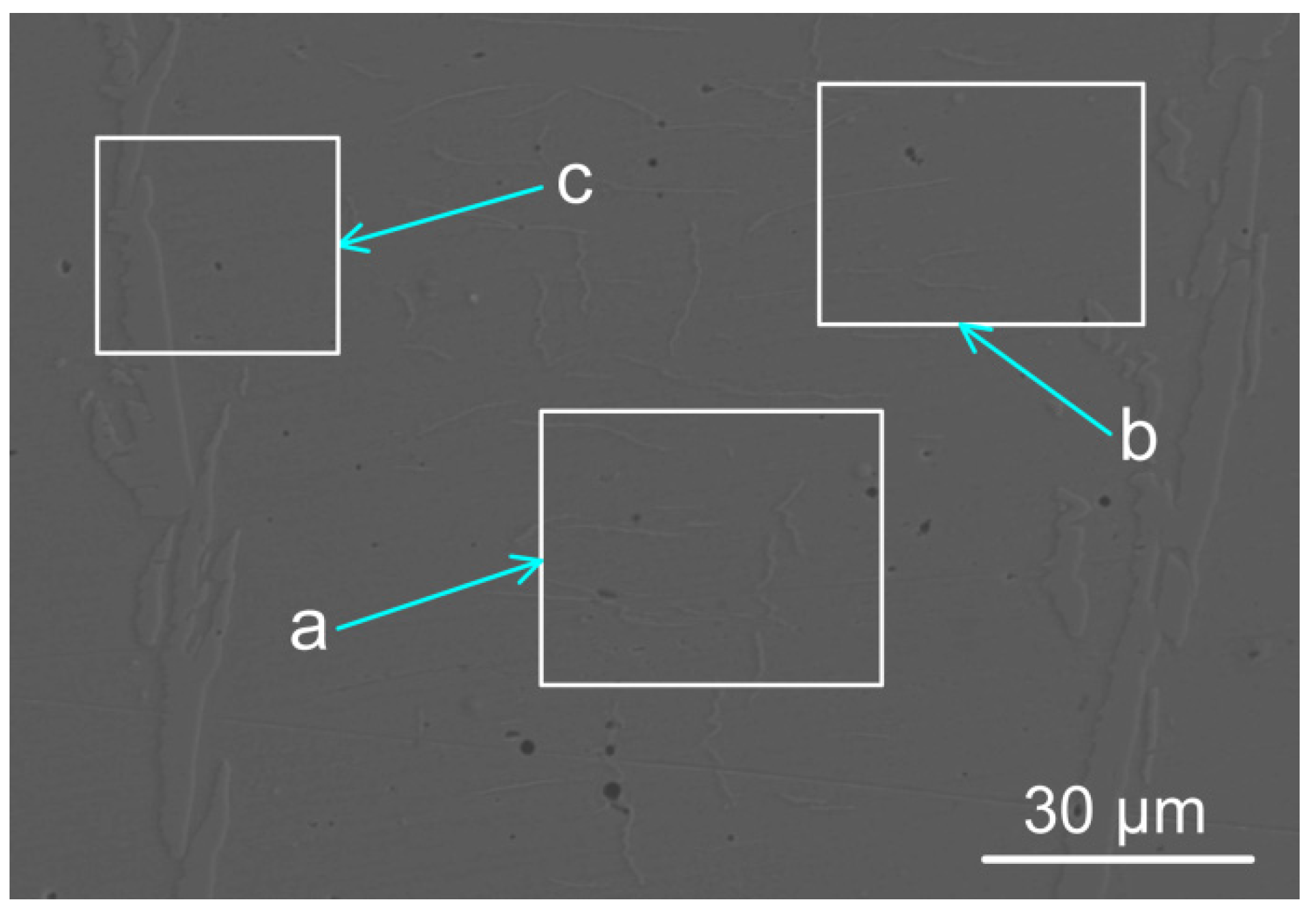
| %Si | %Mn | %Al | %Co | %Fe | |
|---|---|---|---|---|---|
| a | 0.93 | 1.75 | 3.72 | 5.47 | 88.1 |
| b | 0.80 | 1.70 | 3.90 | 5.50 | 88.1 |
| c | 0.90 | 1.70 | 3.70 | 5.40 | 88.3 |
| Al (g) | Co (g) | Powder (g) | Wire (g) | Base Plate (g) | Weld Metal (g) | %DR(wire + MP) | %Al Yield | %Co Yield | |
|---|---|---|---|---|---|---|---|---|---|
| Base Case | 0 | 0 | 0 | 33.8 | 33.8 | 67.6 | 50 | 0 | 0 |
| MP7 | 3.9 | 5.0 | 8.9 | 51.1 | 33.5 | 93.5 | 64 | 55 | 70 |
| SiO2 (g) | MnO (g) | Al (g) | Reaction (2) (kJ) | Reaction (3) (kJ) | Reactions (2) & (3) (kJ) | Weld metal ΔT (°C) | |
|---|---|---|---|---|---|---|---|
| MP7 | 0.53 | 0.67 | 0.49 | −0.96 | −1.57 | −2.53 | 58 |
| Gram Al | %MgF2 | %MgF | %Mg | %AlF3 | %AlF2 | %AlF | %CaF2 | %NaF | %Na | %Mn | %MnF2 | %Co | %SiO | Mass%Co to Gas |
|---|---|---|---|---|---|---|---|---|---|---|---|---|---|---|
| zero | 27 | 5 | 2 | 5 | 3 | 1 | 21 | 12 | 4 | 2 | 2 | 10 | 1 | 10 |
| 3.25 | 7 | 8 | 16 | 1 | 5 | 16 | 7 | 3 | 5 | 9 | <0.5 | 8 | 9 | 16 |
| 6.50 | 2 | 5 | 25 | 0.3 | 3 | 24 | 2 | 1 | 4 | 8 | <0.5 | 7 | 15 | 23 |
Publisher’s Note: MDPI stays neutral with regard to jurisdictional claims in published maps and institutional affiliations. |
© 2022 by the authors. Licensee MDPI, Basel, Switzerland. This article is an open access article distributed under the terms and conditions of the Creative Commons Attribution (CC BY) license (https://creativecommons.org/licenses/by/4.0/).
Share and Cite
Coetsee, T.; De Bruin, F. Application of Unconstrained Cobalt and Aluminium Metal Powders in the Alloying of Carbon Steel in Submerged Arc Welding: Thermodynamic Analysis of Gas Reactions. Appl. Sci. 2022, 12, 8472. https://doi.org/10.3390/app12178472
Coetsee T, De Bruin F. Application of Unconstrained Cobalt and Aluminium Metal Powders in the Alloying of Carbon Steel in Submerged Arc Welding: Thermodynamic Analysis of Gas Reactions. Applied Sciences. 2022; 12(17):8472. https://doi.org/10.3390/app12178472
Chicago/Turabian StyleCoetsee, Theresa, and Frederik De Bruin. 2022. "Application of Unconstrained Cobalt and Aluminium Metal Powders in the Alloying of Carbon Steel in Submerged Arc Welding: Thermodynamic Analysis of Gas Reactions" Applied Sciences 12, no. 17: 8472. https://doi.org/10.3390/app12178472
APA StyleCoetsee, T., & De Bruin, F. (2022). Application of Unconstrained Cobalt and Aluminium Metal Powders in the Alloying of Carbon Steel in Submerged Arc Welding: Thermodynamic Analysis of Gas Reactions. Applied Sciences, 12(17), 8472. https://doi.org/10.3390/app12178472