Article

Optimization Design and Analysis of Bionic Friction Reducing Nozzle in Oil Shale High-Pressure Jet Mining

1
Key Laboratory of Deep Geological Drilling Technology, Ministry of Natural Resources, China University of Geosciences, Beijing 100083, China
2
Sinopec Research Institute of Petroleum Engineering, Beijing 100101, China
*
Author to whom correspondence should be addressed.
Appl. Sci. 2022, 12(16), 8159; https://doi.org/10.3390/app12168159
Submission received: 8 July 2022 / Revised: 3 August 2022 / Accepted: 8 August 2022 / Published: 15 August 2022
(This article belongs to the Section Energy Science and Technology)

Abstract

:
The borehole hydraulic mining method has unique advantages for underground oil shale exploitation. Breaking rock with a high-pressure water jet is a crucial step to ensure the smooth implementation of borehole hydraulic mining in oil shale. The hydraulic performance of the nozzle determines the efficiency and quality of high-pressure water jet technology. To obtain a superior hydraulic performance nozzle, based on the bionic non-smooth theory, a circular groove was selected as the bionic unit to design a bionic straight cone nozzle. The structural parameters of the circular groove include the groove depth, width, and slot pitch. The optimization objective was to minimize the pressure drop, where the fluid has the least resistance. A genetic algorithm was used to optimize the structural parameters of the circular grooves in the inlet and outlet sections of the bionic straight cone nozzle. The optimal structural parameters of the nozzle were as follows: the inlet diameter was 15 mm, the inlet length was 20 mm, the outlet diameter was 4 mm, the length-to-diameter ratio was 3, and the contraction angle was 30°. In addition, in the inlet section, the groove width, slot pitch, and groove depth were 3.9 mm, 5.2 mm, and 5.5 mm, respectively, and the number of circular grooves was 2. Moreover, in the outlet section, the groove width, slot pitch, and groove depth were 2.25 mm, 3 mm, and 5.5 mm, respectively, and the number of circular grooves was 2. The CFD numerical simulation results showed that under the same numerical simulation conditions, compared with the conventional straight cone nozzle, the bionic straight cone nozzle velocity increase rate could reach 13.45%. The research results can provide scientific and valuable references for borehole hydraulic mining of high-pressure water jets in oil shale drilling.

1. Introduction

Oil shale is an unconventional oil and gas resource, as coal, oil, and natural gas provide non-renewable fossil energy [1,2]. Such resources worldwide are abundant, equivalent to more than 400 billion tons of synthetic shale oil, three times the world’s crude reserves [3,4]. The borehole hydraulic mining method has unique advantages for underground oil shale exploitation [5]. As shown in Figure 1, when borehole hydraulic mining technology is used to mine underground oil shale, first, drilling rigs must be used to drill holes that are 100~1000 mm in diameter and pass through oil shale layers. Second, the high-pressure water gun is inserted into the borehole, and the underground oil shale bed is broken into several small pieces by the high-pressure water jet from the nozzle connected to the end of the ejector. Then, it is stripped from the parent rock to form a solid–liquid two-phase flowable slurry at the bottom of the borehole. Finally, pneumatic or hydraulic lifting devices are used to extract slurry to the surface [6]. Borehole hydraulic mining technology has the advantages of low cost, short cycle, reliable use, easy operation, low labor intensity, and little environmental pollution [7].
High-pressure water jet broken rock is crucial to ensure the smooth implementation of oil shale borehole hydraulic mining [8,9]. The entire underground oil shale deposit has to be broken into small pieces of rock and stripped off. A series of follow-up work can be carried out [10,11]. The hydraulic performance of the nozzle determines the efficiency and quality of high-pressure water jet technology [12,13]. Thus, it is necessary to study the hydraulic performance of the nozzle. Due to the mechanical properties of oil shale, it is most easily broken when the water jet is parallel to the bedding direction of the oil shale [14,15]. The primary flow resistance of the straight cone nozzle appears in the outlet section. When drilling hydraulic mining oil shale, a high-pressure water jet often uses a straight cone nozzle because the straight cone nozzle can improve the jet quality [16,17]. The structural parameters of the straight-cone nozzle are the key factors affecting the spray performance of the nozzle [18,19]. The transition from the convergence section to the outlet section must be optimized. It is necessary to reduce the outlet section length as much as possible while satisfying the beam-gathering ability. All the optimization work involves increasing rock breaking effect, saving hydraulic energy, and improving energy conversion efficiency [20,21]. Wen et al. [22] chose a circular annular groove as a bionic unit and arranged the circular annular groove evenly on the inner cavity surface of a straight cone nozzle. The original smooth flow channel inside the nozzle became a bionic non-smooth surface structure, effectively improving the flow channel’s hydraulic characteristics inside the nozzle. However, how the size of the circular annular groove affects the hydraulic characteristics of the internal flow channel of the nozzle has not been studied.
In summary, based on the existing pressure drop formula of the variable cross-section of a circular tube, this study deduced the theoretical formula for the pressure drop calculation of a bionic circular tube (BCT). Using a genetic algorithm, combined with the pressure drop calculation formula of a BCT, the minimum pressure drop was taken as the optimization goal. The circular annular groove structure parameters of the inlet and outlet sections of the bionic straight cone nozzle (BSCN) were optimized. The optimal structural parameters of the BSCN were obtained by using genetic algorithm optimization analysis and CFD numerical simulation results. The drag reduction characteristics of BSCN were further analyzed. The research results can provide scientific and valuable references for borehole hydraulic mining of high-pressure water jets in oil shale drilling. At the same time, it provides a scientific and valuable reference for improving the hydraulic performance of conventional nozzles.

2. Modeling and Optimization Method

2.1. BCT Model and Pressure Drop Calculation

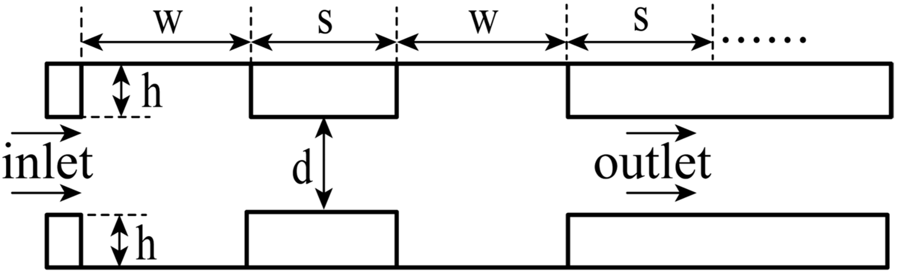
2.1.1. Conceptual Model of a BCT

The bionic non-smooth surface drag reduction technology is based on the principle of bionics [23]. Changing the morphological characteristics of the object surface will change the kinematic and dynamic characteristics of the fluid flowing along the wall [24]. Research on bionic non-smooth surface-drag-reduction technology mainly focused on different rib surfaces [25,26]. Currently, two main drag-reduction mechanisms of bionic non-smooth surfaces are recognized by many scholars, namely, the ‘second vortex group’ theory and the ‘bulgy height’ theory [27,28]. The ‘second vortex group’ theory holds that a small secondary vortex is generated due to the interaction between the backward-rotating flow vortex and the tip of the groove. The existence of the groove restricts the movement of the flow direction vortex, which makes the wall suddenly weak, and ultimately reduces the wall friction [29,30]. The ‘bulgy height’ theory argues that the existence of grooves increases the thickness of the viscous bottom in the boundary layer, resulting in a decrease in friction, which was confirmed by many researchers [31].
The rib drag reduction method was used in many fields and was shown to positively reduce fluid resistance [32,33]. In this study, according to the typical L-shaped rib, we proposed a new type of bionic circular tube (BCT), where the schematic diagram is shown in Figure 2.
As shown in Figure 2, the typical non-smooth surface bionic prototype mainly includes shield scales of shark skin, the mastoid structure of the lotus leaf, the spherical nodular structure of a humpback fin, and radial stripes of scallops. A BCT model was proposed based on the bionic non-smooth surface drag reduction theory. A circular annular groove was uniformly added to the internal flow channel surface of the conventional circular pipe according to certain rules as the bionic unit so that the internal flow channel of the conventional circular pipe was changed from the original smooth flow channel to the bionic non-smooth surface structure. This could improve the kinematic and dynamic characteristics of the fluid flowing on the pipe wall to a certain extent.

2.1.2. Modeling for a Single-Type Variable Cross-Sectional Structure

A single type of circular tube with a variable cross-sectional structure has a reduced or increased diameter, as shown in Figure 3. In a Newtonian fluid, the structure has a mature formula for calculating the pressure drop [34].
In Figure 3, D and d are the large and small diameters (m), respectively; L D s and L d s are the effective lengths of the flow passage generated by the pressure drop in the reduced structure (m), respectively; L D k and L d k are the effective lengths of the flow passage generated by the pressure drop in the increased structure (m), respectively. For the reduced pipe diameter structure [35,36,37] (as shown in Figure 3a), the pressure drop calculation formula is:
Δ p s = ρ g v d 2 v D 2 2 g + h j s
h j s = 0.5 1 d 2 / D 2 2 v d 2 2 g
For the increased pipe diameter structure [35,36,37] (as shown in Figure 3b), the pressure drop calculation formula is:
Δ p k = ρ g v D 2 v d 2 2 g + h j k
h j k = D 2 / d 2 1 2 v D 2 2 g
In these formulas: Δ p s and Δ p k —reduced or increased pipe diameter structure pressure drop (MPa), respectively; D and d—large diameter and small diameter (m), respectively; v D and v d —mean velocity of the large diameter and small diameter cross-sections (m/s), respectively; ρ —liquid density (kg/m3).
When the fluid density is constant, the velocity is inversely proportional to the cross-sectional area. The fluid flow through the contraction channel will accelerate and the flow through the expansion channel will decelerate. Combined with the continuous equation of fluid mechanics, the pressure drops of the pipe diameter reduction or increased structure were further simplified and expressed as:
A D v D = A d v d
D = d + 2 h
Δ p k 1 = ρ d 2 ( d + 2 h ) 2 d 2 ( d + 2 h ) 2 1 v d 2
Δ p s 1 = ρ 3 5 d 2 ( d + 2 h ) 2 + 2 d 2 ( d + 2 h ) 2 2 v d 2 2
In these formulas: Δ p k 1 and Δ p s 1 —simplified increased and reduced pipe diameter structure pressure drops (MPa), respectively; d—trail diameter (m); h—groove depth (m); v D and v d —mean velocities of large diameter and small diameter cross-sections (m/s), respectively; A D and A d —the cross-sectional areas of the large and small paths (m2), respectively; ρ —liquid density (kg/m3).

2.1.3. Modeling for a Comprehensive-Type Variable Cross-Sectional Structure

The comprehensive type of circular tube with a variable cross-sectional structure is a reduction–increase or increase–reduction structure, as shown in Figure 4. For a Newtonian fluid, the structure has a related mature formula for calculating the pressure drop [38,39].
In Figure 4, L d and L D are the length of the reduction section and increase section (m), respectively. For the pipe diameter reduction–increase structure [35,40,41] (as shown in Figure 4a), the pressure drop calculation formula is
Δ p s k = K d Δ p s + Δ p k
K d = 1.01 + 15.46 e n d 0.009 + 0.73 e n d 0.212
In these formulas: Δ p s k is the reduction–increase pipe diameter structure pressure drop; K d is the influence coefficient of the pressure drop of the increased structure; and n d = L d / D , where 0.04 n d 0.2 .
For the increase–reduction pipe diameter structure [35,40,41] (as shown in Figure 4b), the pressure drop calculation formula is
Δ p k s = K D Δ p s + Δ p k
K D = 2.573 2.565 e n D 7.491
In these formulas: Δ p k s is the pressure drop of the increase–reduction pipe diameter structure; K D is the influence coefficient of the pressure drop of the increased structure; and n D = L D / D , where 0.15 n D 0.37 .
Combined with the geometric characteristics of the BCT, the pressure drop of the reduction–increase and increase–reduction pipe diameter structures was further simplified and expressed as
n d 1 = s d + 2 h
n D 1 = w d + 2 h
Δ p s k 1 = 1.01 + 15.46 e s 0.009 ( d + 2 d ) + 0.73 e s 0.212 ( d + 2 h ) ρ 3 5 d 2 ( d + 2 h ) 2 + 2 d 2 ( d + 2 h ) 2 2 v d 2 2
Δ p k s 1 = 2.573 2.565 e w 7 491 ( d + 2 h ) ρ 3 5 d 2 ( d + 2 h ) 2 + 2 d 2 ( d + 2 h ) 2 2 v d 2 2
In these formulas: Δ p s k 1 —reduction–increase BCT pipe diameter structure pressure drop (MPa); Δ p k s 1 —increase–reduction BCT pipe diameter structure pressure drop (MPa); s—slot pitch (m); d—trail diameter (m); h—groove depth (m); w—groove width (m); ρ —liquid density (kg/m3).

2.1.4. Pressure Drop Calculation

According to the superposition of a pressure drop, the pressure drop calculation formula of a BCT is extended as follows:
Δ p = Δ p s k 1 + Δ p k s 1
In this formula: Δ p —BCT pressure drop (MPa); Δ p s k 1 —reduction–increase BCT pipe diameter structure pressure drop (MPa); Δ p k s 1 —increase–reduction BCT pipe diameter structure pressure drop (MPa).

2.2. BSCN model and Optimization

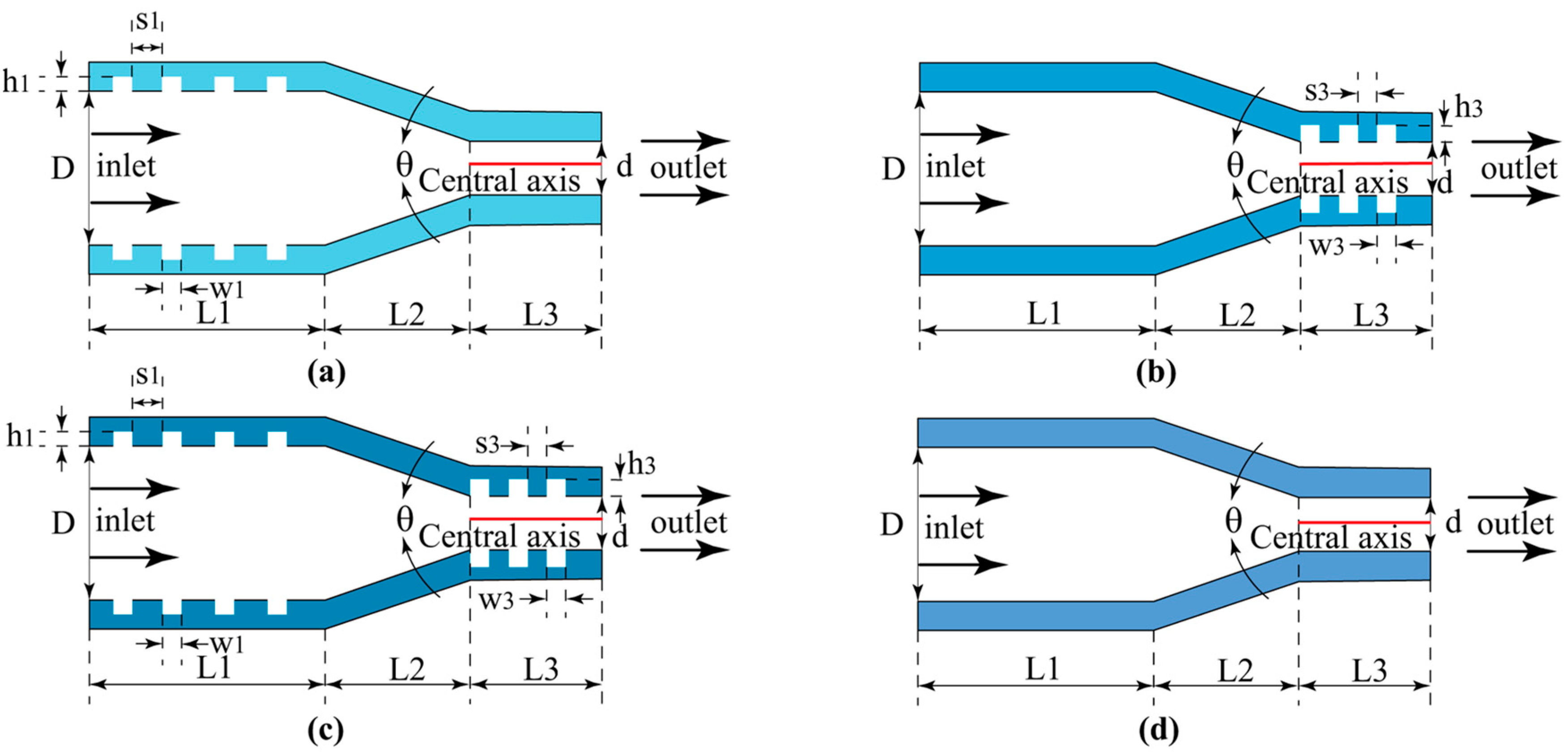
2.2.1. Conceptual Model of the BSCN

In Figure 5, in the conventional straight cone nozzle inlet section L1 and outlet section L3 of the internal flow channel surface, according to a specific uniform rule, a circular groove was added as a bionic unit. The inner pipe of the conventional straight cone nozzle changed from the original smooth flow channel to the bionic non-smooth surface structure, thus forming the BSCN.
As shown in Figure 5, the inlet section L1 and outlet section L3 of the conventional straight cone nozzle were circular tubes. The BSCN model was proposed based on the bionic non-smooth surface drag reduction theory, which can effectively improve the kinematic and dynamic characteristics of fluid flow along the pipe wall to a certain extent.

2.2.2. Optimization Process

The genetic algorithm is a bionic algorithm for solving complex global optimization based on Darwin’s natural evolution theory and genetic variation theory [42]. It draws on natural selection and natural genetic mechanisms in the biological world. It conducts a random search in the solution space based on probability theory and finally finds the optimal solution to the problem [43,44]. A genetic algorithm is a mature optimization algorithm with unique advantages for solving multi-variable optimization problems. It can save the time and cost of experimentation and provide more accurate results.
Figure 6 shows the optimization process of the structural parameters of the BSCN. The BSCN optimization variables’ parameter combinations were converted to the genetic algorithm to identify the search space for processing, and chromosome coding was realized for the parameter data. The constraint function created each generated initial population within the range of values. In the optimization process of genetic algorithms, fitness is an important indicator used to evaluate individual performance. This study selected the objective function as the fitness function to evaluate the fitness.

2.2.3. Objective Function and Constraint Function

To further study the structural parameters of the groove of the BSCN, the pressure drop formula of the BCT was taken as the objective function for the inlet section L1 and the outlet section L3. As shown in Figure 7, a pressure drop calculation formula of the BCT was obtained by selecting a circular groove element:
Δ p = Δ p k s 1 + Δ p s k 1
In this formula: Δ p —BCT pressure drop; Δ p s k 1 —shrinkage–increase BCT structure pressure drop; Δ p k s 1 —expansion–shrinkage BCT pressure drop.
The example Formula (18) was further simplified to the objective function:
Δ p = 3.583 2.565 e w 7.491 ( d + 2 h ) + 15.46 e s 0.009 ( d + 2 h ) + 0.73 e s 0.212 ( d + 2 h ) ρ 3 5 d 2 ( d + 2 h ) 2 + 2 d 2 ( d + 2 h ) 2 2 v d 2 2
In these formulas: d—trail diameter (m); w—groove width (m); s—slot pitch (m); h—groove depth (m); ρ —liquid density (kg/m3); v d —flow rate at the inlet (m/s).
Combined with the constraint conditions of Formula (18), the following constraint function was obtained:
0.04 s d + 2 h 0.2 0.15 w d + 2 h 0.37
In this formula: d—trail diameter (m); w—groove width (m); s—slot pitch (m); h—groove depth (m).

2.2.4. Basic Structure Parameters

Combined with the structural parameters of the conventional straight cone nozzle, the structural parameters of the BSCN were determined. As shown in Table 1, the BSCM mainly increased the three structural parameters of groove depth, groove width, and slot pitch compared with the conventional straight cone nozzle.
For the inlet section L1 and outlet section L3 of the BSCN, according to the example Formula (19) of the BCT, the inlet velocity of the inlet section L1 of the bionic straight cone nozzle was 1 m/s, the inlet velocity of the outlet section L3 of the BSCN was 14 m/s, and the liquid density was 1 kg/m3. The inlet section L1 and outlet section L3 of the BSCN were regarded as two BCTs, and the minimum pressure drop of the BCT was taken as the optimization objective. In the range of 0.1 mm–14.5 mm in groove depth, the genetic algorithm was used to analyze and solve the pressure drop example in Formula (19), and the groove width and slot pitch of the structural parameters of the BSCN were obtained.

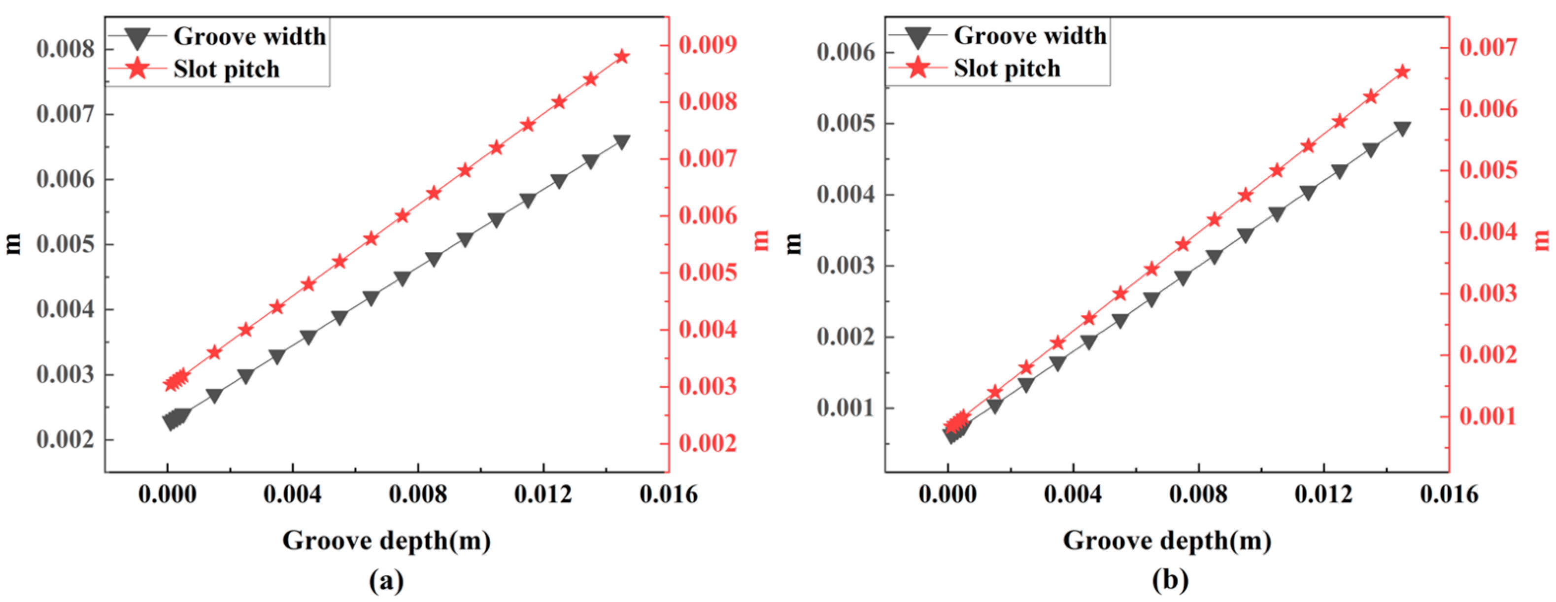
2.2.5. Optimization Results

The inlet section L1 and outlet section L3 of the BSCN were regarded as two BCTs. The inlet velocity of the inlet section L1 of the BSCN was 1 m/s, the inlet velocity of the outlet section L3 of the BSCN was 14 m/s, and the liquid density was 1 kg/m3. In the groove depth range 0.1 mm–14.5 mm, the genetic algorithm was used to analyze and solve Formula (19) for the pressure drop example and the groove width, and the slot pitch of the structural parameters of a circular groove unit of the BSCN was obtained.
As shown in Figure 8, in the groove depth range of 0.1 mm ~ 14.5 mm, the minimum pressure drop of the BCT was taken as the optimization objective, and the genetic algorithm was used to solve the objective function. The values of the groove width and slot pitch could be obtained. The values of the groove width and slot pitch spacing obtained showed a linear change trend.

3. Case Study

3.1. CFD Numerical Simulation

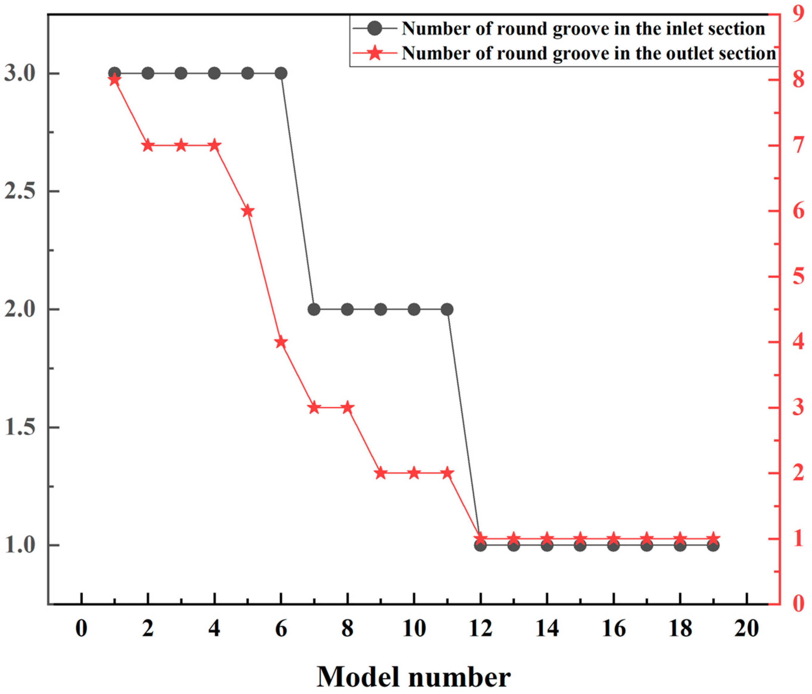
3.1.1. Determining the Number of BSCN Grooves

Based on the optimization results of the genetic algorithm, the number of grooves in the inlet and outlet sections of the BSCN was determined by combining the terms in the following Formula (21), as shown in Figure 9. The models of the BSCN and conventional straight cone nozzle were established.
n 1 max × ( s 1 + w 1 ) L 1 n 3 max × ( s 3 + w 3 ) L 3
In this formula, n1 and n3 are the maximum positive integers, respectively; w1 and s1 are the groove width and slot pitch of the inlet section of the BSCN, respectively; and L1 is the length of the inlet section of the BSCN. w3 and s3 are the groove width and slot pitch of the outlet section of the BSCN, respectively, and L3 is the length of the outlet section of the BSCN.

3.1.2. Basic Settings for Numerical Simulation

COMSOL Multiphysics software was used for the simulation. The inlet velocity was 1 m/s and the outlet was under a static pressure condition. The fluid was incompressible, the wall material of the model was set to ordinary steel, the turbulence model ( k ξ ) was selected, the mesh size was selected to be more refined, and the calibration was fluid dynamics. The maximum unit size was 0.91 mm, the minimum unit size was 0.026 mm, and the boundary layer number was set to 8. The solver selected was the steady-state solver. The velocity in each model was analyzed using CFD numerical simulation.

3.1.3. Analysis of Simulation Results

As shown in Figure 10, based on CFD numerical simulation results, the velocity along the L3 axis of each BSCN and the conventional straight cone nozzle was extracted, and then the average value was taken.
The average velocity along the central L3 axis of each BSCN was subtracted from the average velocity on the L3 central axis of the conventional straight cone nozzle. The obtained results were divided by the average velocity along the central axis of L3 in the outlet of the conventional straight cone nozzle, and finally, the velocity increase rate of the BSCN was obtained. Then, the curves of the velocity rise rate of each BSCN were drawn, as shown in Figure 11.
η 0 = V bn V cn V c n × 100 %
In this formula: η 0 —the rate of velocity increase; V bn —average velocity along the axis of the BSCN (m/s); V cn —average velocity along the central axis of the conventional straight cone nozzle (m/s).
It can be observed from Figure 11 that the velocity increase rate of the BSCN was more significant than zero after the structural parameters were optimized. It was further noted that the resistance against the fluid flowing through the inner wall was reduced by setting circular grooves in the inlet and outlet sections of the conventional straight cone nozzle, and the drag reduction effect of the outlet section of the BSCN was better than that of the inlet section.
In the optimized BSCN model, in the L1 inlet section, the groove width was 3.9 mm, the slot pitch was 5.2 mm, the groove depth was 5.5 mm, and the number of grooves was 2. In the L3 outlet section, the groove width was 2.25 mm, the slot pitch was 3 mm, the groove depth was 5.5 mm, and the number of grooves was 2. The maximum velocity increase rate was 13.45%, and the drag reduction effect was the best.

3.2. Analysis of the Effect

Figure 12 is the velocity vector diagram of the BSCN with the best drag reduction effect and a velocity increase rate of 13.45%. In Figure 12, each circular annular groove contained a swirl opposite the direction of the internal flow.
As shown in Figure 13, the BSCN and the conventional straight cone nozzle were divided perpendicular to the axis. The first dividing line was at the left end of the first circular groove, the second dividing line was located at the middle line of the first circular groove slot pitch in the inlet section, the third dividing line was located at the right end of L1, the fourth dividing line was located at the left end of L3, the fifth dividing line was located at the middle line of the first circular groove slot pitch in the outlet section, and the sixth dividing line was located at the right end of L3.
As shown in Figure 14, based on the results of the CFD numerical simulation, the value of the velocity at each dividing line was extracted, and the curve of the change in the velocity at each dividing line with the distance of the dividing line was plotted. Line01/line1 to line06/line6 represent the positions shown in Figure 13.
It can be concluded from Figure 14a that in the inlet section, the velocity of the BSCN at different positions perpendicular to the axis was greater than that of the conventional straight cone nozzle at a distance of 2 mm from the wall. It can be seen from Figure 14b that in the outlet section, at the position of 0.75 mm away from the wall, the velocity of the BSCN at different positions perpendicular to the axis was greater than that of the conventional straight cone nozzle. In the outlet section, compared with the conventional straight cone nozzle, the BSCN improved the fluid velocity and had a more vital constraint on the fluid.

4. Conclusions

(1)
Under the same numerical simulation conditions, compared with the conventional straight cone nozzle, the velocity increase rate of the BSCN could reach 13.45%. This can provide valuable scientific references for the hydraulic mining of high-pressure water jets in oil shale drilling.
(2)
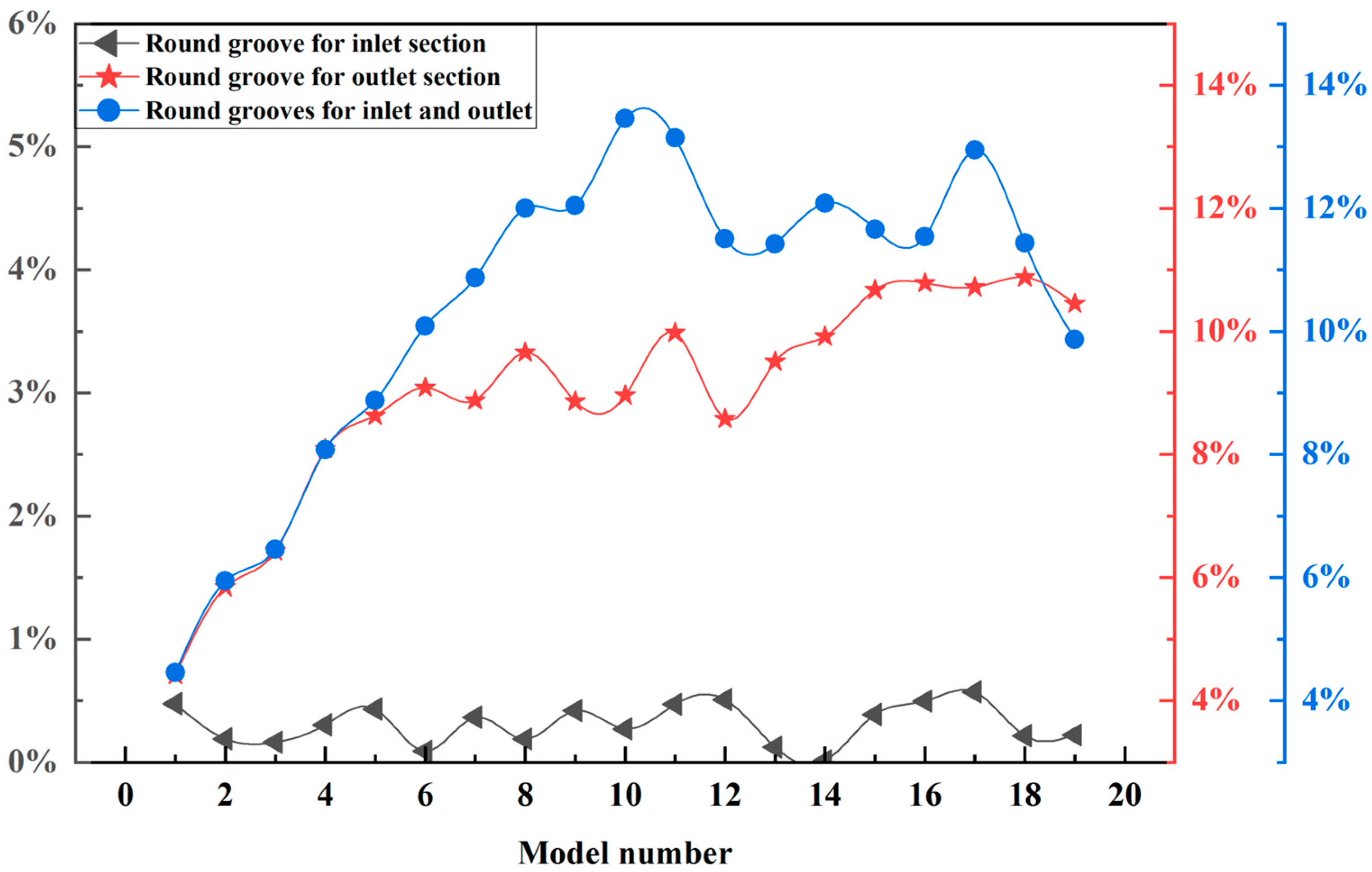
CFD numerical simulation results showed that the circular groove in the inlet and outlet sections could effectively reduce the fluid resistance. The drag reduction effect of the circular groove arranged in the outlet section of BSCN was better than that arranged in the inlet section.
(3)
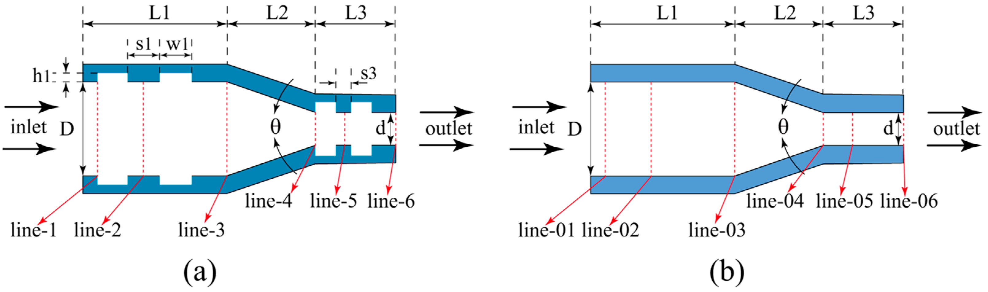
Based on the results of genetic algorithm optimization analysis and CFD numerical simulation, the optimal structural parameters of the BSCN were as follows: Fixed values were inlet diameter D = 15 mm, inlet length L1 = 20 mm, outlet diameter d = 4 mm, L3/d = 3, and contraction angle θ = 30°. Variable values for the inlet section of L1, namely, the groove width, slot pitch, and groove depth, were 3.9 mm, 5.2 mm, and 5.5 mm, respectively, and the number of circular grooves was 2. In the outlet section of L3, the groove width, slot pitch, and groove depth were 2.25 mm, 3 mm, and 5.5 mm, respectively, and the number of circular grooves was 2.
Future work is planned to manufacture the real object of the BSCN and conduct a series of experiments. At the same time, in addition to the bionic unit used in this study, we can also try to find different types of bionic units to explore nozzles with better hydraulic performance.

Author Contributions

Conceptualization, J.Z. and Y.L.; Methodology, J.Z.; Software, J.Z. and Z.D.; Formal analysis, J.Z., Y.L. and X.Q.; Writing—original draft preparation, J.Z.; Writing—review and editing, X.X.; Funding acquisition, Y.L., X.Q. and J.L.; Visualization, J.Z., Y.L. and J.L. All authors have read and agreed to the published version of the manuscript.

Funding

The research was funded by the Natural Science Foundation of China (No. 42002307), Fundamental Research Funds for the Central Universities, China (No. 2652019070).

Institutional Review Board Statement

Not applicable.

Informed Consent Statement

Not applicable.

Data Availability Statement

Data are contained within the article.

Acknowledgments

The authors would like to thank the editor and the reviewers for their helpful comments.

Conflicts of Interest

The authors declare no conflict of interest.

References

  1. Zhu, G.; Zhang, B.; Zhao, P.; Duan, C.; Zhao, Y.; Zhang, Z.; Yan, G.; Zhu, X.; Ding, W.; Rao, Z. Upgrading low-quality oil shale using high-density gas-solid fluidized bed. Fuel 2019, 252, 666–674. [Google Scholar] [CrossRef]
  2. Brendow, K. Global oil shale issues and perspectives (Synthesis of the Symposium on Oil Shale held in Tallinn (Estonia) on 18 and 19 November 2002). Oil Shale 2003, 20, 81–92. [Google Scholar]
  3. Knaus, E.A.; Killen, J.B.; Biglarbigi, K.A.; Crawford, P.A. An Overview of Oil Shale Resources; ACS Symposium Series: Washington, DC, USA, 23 February 2010; pp. 3–20. [Google Scholar]
  4. Dyni, J.R. Geology and Resources of Some World Oil-Shale Deposits. Oil Shale 2003, 20, 193–252. [Google Scholar]
  5. Kang, Z.; Zhao, Y.; Yang, D. Review of oil shale in-situ conversion technology. Appl. Energy 2020, 269, 115121–115139. [Google Scholar] [CrossRef]
  6. Jiwei, W.; Chen, C. Optimizing the Structure of the Straight Cone Nozzle and the Parameters of Borehole Hydraulic Mining for Huadian Oil Shale Based on Experimental Research. Energies 2017, 10, 2021–2035. [Google Scholar]
  7. Xu, Y.; Sun, P.; Yao, S.; Liu, Z.; Tian, X.; Li, F.; Zhang, J. Progress in exploration, development and utilization of oil shale in China. Oil Shale 2019, 36, 285–304. [Google Scholar] [CrossRef]
  8. Zhabin, A.; Polyakov, A.; Averin, E.; Khachaturian, W. Experimental studies on cutting oil shale by high-pressure water jets. Oil Shale 2019, 36, 32–42. [Google Scholar] [CrossRef]
  9. Dongqing, Z.; Jingbin, L.; Xiao, H.; Xin, L.; Kang, C. Flow field simulation of swirling abrasive jet nozzle for hard rock breaking. Geofluids 2022, 2022, 4681189. [Google Scholar] [CrossRef]
  10. Wen, J.; Chen, C.; Urso, C.; Yang, X.J. Experimental research on the performances of water jet devices and proposing the parameters of borehole hydraulic mining for oil shale. PLoS ONE 2018, 13, e0199027. [Google Scholar] [CrossRef]
  11. Pedchenko, L.; Pedchenko, N.; Manhura, A.; Pedchenko, M. Development of natural bitumen (bituminous sands) deposits based on the technology of hydraulic mining by boreholes. In Proceedings of the E3S Web of Conferences, Odesa, Ukraine, 22 October 2019; pp. 01036–01050. [Google Scholar]
  12. Jian, Z.; Zhang, G.; Xu, Y.; Lin, A.; Yang, D. Enhancing rate of penetration in a tight formation with high-pressure water jet (HPWJ) via a downhole pressurized drilling tool. J. Pet. Sci. Eng. 2019, 174, 1194–1207. [Google Scholar]
  13. Hja, C.; Hz, A.; Kg, B.; Ow, A.; Yw, A.; Dm, A. Numerical investigation of hard rock breakage by high-pressure water jet assisted indenter impact using the coupled SPH/FEM method. Powder Technol. 2020, 376, 176–186. [Google Scholar]
  14. Chen, S.; Yin, D.; Jiang, N.; Wang, F.; Zhao, Z. Mechanical properties of oil shale-coal composite samples. Int. J. Rock Mech. Min. Sci. 2019, 123, 104120–104130. [Google Scholar] [CrossRef]
  15. He, Q.; He, B.; Li, F.; Shi, A.; Chen, J.; Xie, L.; Ning, W. Fractal characterization of complex hydraulic fractures in oil shale via topology. Energies 2021, 14, 1123. [Google Scholar] [CrossRef]
  16. Spotts, N.G.; Guzik, S.; Gao, X. A CFD analysis of compressible flow through convergent-conical nozzles. In Proceedings of the 49th AIAA/ASME/SAE/ASEE Joint PropulsionConference, San Jose, CA, USA, 15–17 July 2013; p. 3734. [Google Scholar]
  17. Mao, J.S.; Sun, Y.H.; Wen, J.W.; Chen, C. Research on Nong’an oil shale hydraulic breaking. Appl. Mech. Mater. 2013, 398, 7–10. [Google Scholar] [CrossRef]
  18. Shen, Y.; Huang, Y.Q.; Ye, R.F.; Ding, S.; Wang, L.; Lin, C.; Gu, Y. A new design of the laser-micro jet system. In Proceedings of the 2009 Symposium on Photonics and Optoelectronics, Wuhan, China, 14–16 August 2009; pp. 1–4. [Google Scholar]
  19. Chen, L.; Cheng, M.; Cai, Y.; Guo, L.; Gao, D. Design and Optimization of High-Pressure Water Jet for Coal Breaking and Punching Nozzle Considering Structural Parameter Interaction. Machines 2022, 10, 60. [Google Scholar] [CrossRef]
  20. Jiang, T.-W.; Huang, Z.-W.; Li, J.-B.; Zhou, Y.-S. Internal flow mechanism of cone-straight nozzle. Pet. Sci. 2021, 18, 1507–1519. [Google Scholar] [CrossRef]
  21. Jiang, T.; Huang, Z.; Li, J.; Zhou, Y.; Xiong, C. Effect of Nozzle Geometry on the Flow Dynamics and Resistance Inside and Outside the Cone-Straight Nozzle. ACS Omega 2022, 7, 9652–9665. [Google Scholar] [CrossRef] [PubMed]
  22. Wen, J.; Chen, C.; Qi, Z.; Campos, U.; Pei, X. Bionic optimum design of straight cone nozzle and the effectiveness evaluation of reducing fluid resistance. J. Braz. Soc. Mech. Sci. Eng. 2019, 41, 358. [Google Scholar] [CrossRef]
  23. Zhu, Z.; Li, J.; Peng, H.; Liu, D. Nature-Inspired Structures Applied in Heat Transfer Enhancement and Drag Reduction. Micromachines 2021, 12, 656. [Google Scholar] [CrossRef]
  24. Bhushan, B. Biomimetics: Lessons from nature–an overview. Philos. Trans. R. Soc. A: Math. Phys. Eng. Sci. 2009, 367, 1445–1486. [Google Scholar] [CrossRef]
  25. Wilkinson, S.; Anders, J.; Lazos, B.; Bushnell, D. Turbulent drag reduction research at NASA Langley: Progress and plans. Int. J. Heat Fluid Fl. 1988, 9, 266–277. [Google Scholar] [CrossRef]
  26. Liu, C.; Sheng, C.; Yang, H.; Yuan, Z. Design and optimization of bionic janus blade in hydraulic torque converter for drag reduction. J. Bionic Eng. 2018, 15, 160–172. [Google Scholar] [CrossRef]
  27. Dean, B.; Bhushan, B. Shark-skin surfaces for fluid-drag reduction in turbulent flow: A review. Philos. Trans. R. Soc. A Math. Phys. Eng. Sci. 2010, 368, 4775–4806. [Google Scholar] [CrossRef]
  28. Bechert, D.; Reif, W. On the drag reduction of the shark skin. In Proceedings of the 23rd Aerospace sciences meeting, Reno, NV, USA, 14–17 January 1985; p. 546. [Google Scholar]
  29. Walsh, M.; Lindemann, A. Optimization and application of riblets for turbulent drag reduction. In Proceedings of the 22nd Aerospace Sciences Meeting, Reno, NV, USA, 9–12 January 1984; p. 347. [Google Scholar]
  30. Bechert, D.; Bruse, M.; Hage, W.; Meyer, R. Fluid mechanics of biological surfaces and their technological application. Naturwissenschaften 2000, 87, 157–171. [Google Scholar] [CrossRef]
  31. Bechert, D.; Bruse, M.; Hage, W.v.; Van der Hoeven, J.T.; Hoppe, G. Experiments on drag-reducing surfaces and their optimization with an adjustable geometry. J. Fluid Mech. 1997, 338, 59–87. [Google Scholar] [CrossRef]
  32. Yunqing, G.; Tao, L.; Jiegang, M.; Zhengzan, S.; Peijian, Z. Analysis of drag reduction methods and mechanisms of turbulent. Appl. Bionics Biomech. 2017, 2017, 6858720. [Google Scholar] [CrossRef] [PubMed]
  33. Liu, E.; Li, L.; Wang, G.; Zeng, Z.; Zhao, W.; Xue, Q. Drag reduction through self-texturing compliant bionic materials. Sci. Rep. 2017, 7, 40038. [Google Scholar] [CrossRef] [PubMed]
  34. Chen, I.Y.; Wongwises, S.; Yang, B.-C.; Wang, C.-C. Two-phase flow across small sudden expansions and contractions. Heat Transf. Eng. 2010, 31, 298–309. [Google Scholar] [CrossRef]
  35. Liu, J.; Yao, L.; Zhang, Y.; Chen, J. The Calculation Method of Local Pressure Drop on Variable Cross-Section Circular Tube Structure. Mach. Des. Manuf. 2016, 5, 83–87. [Google Scholar]
  36. Zhao, B.-F.; Jin, Y.-Z.; Men, B.-H. The Study on Pipe Sudden Enlargement Local Resistant Coefficient. J. Northeast Agric. Univ. 1999, 6, 147–151. [Google Scholar]
  37. Roul, M.K.; Dash, S.K. Two-phase pressure drop caused by sudden flow area contraction/expansion in small circular pipes. Int. J. Numer. Methods Fluids 2011, 66, 1420–1446. [Google Scholar] [CrossRef]
  38. Hermany, L.; dos Santos, D.D.O.; Frey, S.; Naccache, M.F.; De Souza Mendes, P.R. Flow of yield-stress liquids through an axisymmetric abrupt expansion-contraction. J. Non-Newton. Fluid Mech. 2013, 201, 1–9. [Google Scholar] [CrossRef]
  39. Dos Santos, D.D.O.; Frey, S.L.; Naccache, M.F.; de Souza Mendes, P.R. Flow of elasto-viscoplastic liquids through a planar expansion–contraction. Rheol. Acta 2014, 53, 31–41. [Google Scholar] [CrossRef]
  40. Yao, L.; Liu, J.; Li, X.; Yue, Q.; Liu, Y.; Wang, H. Application of the building block approach to characterize the pressure loss of water and fracturing fluid in contraction-expansion pipe. J. Pet. Sci. Eng. 2019, 176, 51–61. [Google Scholar] [CrossRef]
  41. Wu, J.H.; Ai, W.Z. Flows through energy dissipaters with sudden reduction and sudden enlargement forms. J. Hydrodyn. 2010, 22, 360–365. [Google Scholar] [CrossRef]
  42. Mirjalili, S. Genetic algorithm. In Evolutionary algorithms and neural networks; Springer: Cham, Switzerland, 2019; pp. 43–55. [Google Scholar]
  43. Kumar, M.; Husain, D.; Upreti, N.; Gupta, D. Genetic algorithm: Review and application. Int. J. Inf. Technol. Knowl. Manag. 2010, 2, 451–454. [Google Scholar] [CrossRef]
  44. Katoch, S.; Chauhan, S.S.; Kumar, V. A review on genetic algorithm: Past, present, and future. Multimed. Tools Appl. 2021, 80, 8091–8126. [Google Scholar] [CrossRef] [PubMed]
Figure 1. Borehole hydraulic mining schematic diagram.
Applsci 12 08159 g001
Figure 2. Concept diagram of a BCT (note: d is the diameter (m), h is the groove depth (m), w is the groove width (m), and s is the slot pitch (m).
Applsci 12 08159 g002
Figure 3. Schematic diagram of the pipe structure with a reduced or increased diameter. (a) reduced structure; (b) increased structure.
Applsci 12 08159 g003
Figure 4. Schematic diagram of pipe diameter reduction–increase and increase–reduction structures. (a) reduction–increase structure; (b) increase–reduction structure.
Applsci 12 08159 g004
Figure 5. Concept diagram of BSCN.
Applsci 12 08159 g005
Figure 6. BSCN optimization flow chart.
Applsci 12 08159 g006
Figure 7. BCT schematic diagram.
Applsci 12 08159 g007
Figure 8. Groove width and slot pitch change under different groove depths: (a) inlet section of the BSCN and (b) outlet section of the BSCN.
Applsci 12 08159 g008
Figure 9. The number of circular ring grooves in the inlet and outlet sections.
Applsci 12 08159 g009
Figure 10. Conceptual model: (ac) BSCN and (d) conventional straight cone nozzle.
Applsci 12 08159 g010
Figure 11. Velocity increase rate of the BSCN.
Applsci 12 08159 g011
Figure 12. The velocity vector of a BSCN.
Applsci 12 08159 g012
Figure 13. Line plan:(a) BSCN; (b) conventional straight cone nozzle.
Applsci 12 08159 g013
Figure 14. Velocity distribution along lines in the line plan: (a) Line01/line1 to line03/line3 plan; (b) Line04/line4 to line06/line6 plan.
Applsci 12 08159 g014
Table 1. Structural parameters of the BSCN.
ParameterDdL1L3θhws
Value15 mm4 mm20 mm12 mm30°------
Publisher’s Note: MDPI stays neutral with regard to jurisdictional claims in published maps and institutional affiliations.

