Abstract
The high penetration of photovoltaic (PV) systems in low-voltage distribution networks relieves the pressure of energy shortages. However, the severe intermittency and variability in the output of PVs also bring a series of voltage quality problems, such as over-voltage, under-voltage, and voltage fluctuations. In this paper, a novel voltage control strategy based on air conditioners (ACs) and an on-load-tap-changer (OLTC) is proposed. By regulating the operating power of the ACs, voltage regulation powers are provided for the distribution network during the regulation time delays of the OLTC, which can effectively avoid the occurrence of regulation lag by the OLTC. The thermal model and electrical model are established to evaluate the operating performance of voltage regulation potential of the ACs. Furthermore, the voltage regulation strategy is formulated based on the regulation potential of the ACs, which it can make full use of. The effectiveness of the proposed voltage control strategy is illustrated in numerical studies.
1. Introduction
Developing the photovoltaic (PV) industry can effectively deal with the problems of energy shortages and environmental pollution. However, the outputs of PVs have intermittence and randomness [1]. The high penetration of PVs brings a series of benefits to the world but also poses great challenges to the stability and security of distribution networks. An enormous number of PVs on the user side may cause an inverse power flow and increase the voltage, even leading to an over-voltage problem [2]. In addition, when the output of PVs decreases, the surge in daily load may cause an under-voltage problem [3]. These over-voltage and under-voltage problems make the voltage optimization of the distribution network more complicated.
Voltage regulation plays a crucial role in keeping the power balance between generation and consumption. The fundamental voltage problem, without considering the PVs, can be easily resolved by resetting the tap position of on-load tap changers (OLTCs) [4]. Abolfazl Babaei et al. [5] propose a model that could show the transient behavior of OLTCs. The proposed model can simulate the recovery voltages and switch current waveform during transient and steady-state conditions. Jiayan Liu et al. designed a fuzzy controller to operate the OLTC for voltage regulation. The regulation process does not require an accurate mathematical model between voltage and tap position [6]. However, due to the time delays of the regulation process, the action of the OLTC is slow, which results in the tap of the OLTC not being able to respond frequently to the voltage regulation of the distribution network [7]. In addition, an OLTC is vulnerable to being damaged and needs expensive maintenance, so the action of the OLTC should avoid being too frequent [8]. Therefore, facing the distribution network with a high penetration of PVs, the OLTC cannot cope with the voltage problems of the distribution network alone.
With the development of the smart grid, a flexible load can be remotely controlled to optimize the voltage of a distribution network through demand response technology [9]. Among the numerous flexible loads, air conditioners (ACs) contribute to almost 40% of the total power demand in the United States [10]. In addition, the insulation of buildings has improved, allowing the ACs to change the operating power with little effect on room temperature. The development of microelectronic technology and frequency conversion technology makes the compressor speed of the AC adjust continuously [11]. In this way, the inverter AC can flexibly participate in voltage regulation. Therefore, inverter ACs are suitable and have enormous potential to participate in voltage regulation for the distribution network.
Dongxiao Wang et al. equivalent an inverter AC to the virtual battery and regulate the low-voltage distribution network voltage by coordinating distributed VESSs [12]. Additionally, Ke Meng et al. provide a hierarchical control scheme to coordinate multiple groups of AC controlled loads to regulate network loading and voltage in a distribution network [13]. However, due to the limited quality of ACs on the user side, the ACs cannot afford massive regulation power. In addition, changing the operating power of ACs would affect the room temperature, negatively impacting the comfort of occupants [14]. Therefore, the ACs cannot provide a voltage regulation service for long.
To address the above problems, a novel voltage regulation strategy with coordinated control of an OLTC and ACs is proposed. When the distribution network encounters a voltage problem, the ACs provide a voltage regulation service during the time delays of the OLTC. After the regulation action of the OLTC finishes, the ACs quit the regulation service. In this manner, the voltage regulation can be responded to quickly. The voltage regulation potential of the ACs and OLTC can be fully utilized. The contributions of this paper can be described as follows:
- (1)
- A detailed thermal and electrical model is developed for a voltage regulation service. Based on the models, the voltage regulation potential can be evaluated to formulate the voltage regulation strategy of the ACs, making full use of the voltage regulation potential.
- (2)
- A novel voltage regulation method is proposed by coordinating the control of the OLTC and ACs. In the regulation process, the ACs take priority in voltage regulation during the time delays of the OLTC. In this manner, the slow action defect of the OLTC can be offset.
- (2)
- A voltage ranking optimization algorithm is proposed. The algorithm considers preferentially regulating the node with the most severe voltage problem, which can utilize less regulation power for voltage optimization.
2. The Voltage Regulation Model
2.1. The Model of OLTC
As traditional voltage regulation equipment, the OLTC can adjust the tap position to realize the voltage regulation. The inner control of the OLTC is shown in Figure 1.
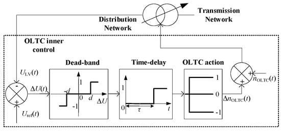
Figure 1.
The inner control of OLTC.
If the difference between the voltage reference and the distribution network voltage exceeds the dead band, the OLTC will change a tap. Each variation of a tap has a voltage change at the secondary side of the transformer. The action of the OLTC has a time delay in the voltage regulation service [15]. The voltage variation can be expressed as:
where and are the voltage array of the distribution network at the current time and previous time. is the variable number of taps. is the voltage variation in each tap. , and is the number of nodes.
2.2. Thermal Model of a Room
The thermal model of a room should be built to describe the thermal dynamic variation and evaluate the room temperature. The room temperature variation is mainly affected by the operating states of the ACs and the temperature difference between the room temperature and the ambient temperature [16]. In addition, disturbances such as thermal radiation of the occupants, electrical equipment and sunlight also impact the room temperature variation. Therefore, the thermal model can be expressed as follows [11]:
where and are the heat capacity and the density of the air, respectively. and are the volume and the surface area of the room, respectively. and are the room temperature and ambient temperature, respectively. is the heat gain. is the cooling power of the AC. is the heat transfer coefficient from indoors to outdoors. is the exchange times of air. is the heat gain of other disturbances.
2.3. Electrical Model of a Room
Compared with a regular constant-frequency AC, the operating frequency of the inverter AC compressor can be adjusted continuously. Therefore, the operating power and the cooling power of the inverter AC are adjustable, which can be expressed as:
where is the operating frequency of the compressor. and are the coefficients of the operating power calculation equation. , , and are the coefficients of the cooling power calculation equation.
When the room temperature stabilizes at the set temperature, the cooling power provided by the AC is equal to the heat gain of the room. At this time, the compressor frequency can be expressed as:
3. Voltage Regulation Performance of the AC
Several indexes should be calculated to evaluate the performance and voltage regulation potential, including capacity, over-voltage regulation power, and under-voltage regulation power.
3.1. Capacity
AC can convert electric energy into heat energy and store it in a room. Additionally, the power consumption pressure of the distribution network can be relieved by decreasing the operating power of ACs. However, when the operating power of the AC is regulated, the room temperature should be kept within [Tmin, Tmax] to avoid affecting the comfort of occupants. Therefore, the capacity can be expressed as:
where and are the maximum and minimum of the comfortable temperature.
3.2. Over-Voltage/Under-Voltage Regulation Power
The compressors work at to keep the room temperatures at the set temperatures if the ACs do not participate in the regulation service. When the distribution network encounters an over-voltage problem, the compressor increases the operating frequency to provide regulation power for over-voltage regulation; when the distribution network encounters an under-voltage problem, the compressor decreases the operating frequency to provide regulation power for under-voltage regulation. The regulation power can be expressed as follows:
where is the regulation power for the over-voltage problem; when the compressor frequency works at the max operating frequency , the regulation power for the over-voltage problem reaches maximum. is the regulation power for the under-voltage problem, and when the compressor frequency works at the min operating frequency , the regulation power for the under-voltage problem reaches the minimum.
3.3. Residual Regulation Capacity
The residual regulation capacity can be used to describe the room of the energy storage state, which relates to the comfortable temperature of the room [, ]. The difference between and room temperature can describe the residual regulation capacity of the room:
4. Voltage Regulation Strategy
The OLTC has a time delay when the tap position changes to respond to the voltage problems. The ACs have huge voltage regulation potential that can provide a voltage regulation service during the time delay of the OLTC through demand-response technology. The voltage regulation strategy includes three processes when coordinating control of the OLTC and ACs. When the distribution network has a voltage problem, the tap position of the OLTC is adjusted according to the voltage violations. Due to the time delay of the OLTC’s action, the ACs will regulate the operating power to provide the voltage regulation service. The room temperature should be controlled within [Tmin, Tmax] to avoid impacting the comfort of occupants during the voltage regulation service provided by ACs. After the time delay of the OLTC finishes, the ACs exit the voltage regulation service.
The number of ACs on the user side is limited, which cannot provide enormous regulation power for the distribution network. Therefore, when calculating the regulation power provided by the ACs, the quantity of ACs should be considered. This paper proposes a voltage ranking optimization algorithm to calculate the voltage regulation power provided by the limited ACs.
The voltage should be controlled within a limited range in the distribution network to avoid harming electrical equipment on the user side. The brief distribution network model is shown in Figure 2. The nodal voltage can be obtained according to the information on the power flow:
where and are the nodal voltages at node n and n − 1. is the impedance between node n − 1 and node n on the distribution line. is the output current of PV at node n. is the current flowing into node n for the load at the user side. It can be seen from (11) that the main factors affecting the fluctuations of nodal voltage are and . The power consumption of ACs accounts for a huge proportion of daily loads. Therefore, regulating the operating power of the ACs at the node with the most severe voltage problem can solve the voltage problem of the distribution network. The PID algorithm can obtain the regulation power of the ACs:
where is the difference between nodal voltage and setpoint. , , and are the coefficients of the PID algorithm. When the ACs of node n cannot provide enough regulation to keep the voltage of the distribution network within the permissive range, the ACs of the adjacent node will provide the regulation power for the voltage regulation.
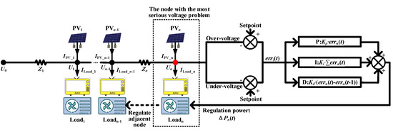
Figure 2.
The distribution network model and regulation strategy.
According to the voltage regulation performance of the ACs, the voltage regulation potential can be evaluated. To make full use of the voltage regulation potential of the ACs, classifying will be implemented based on the . The classification process is shown in Figure 3. The ACs are classified into five groups in this paper. During over-voltage regulation, the s of each group are [0.975, +∞] (Group 0), [0.75, 0.975], [0.5, 0.75], [0.25, 0.5], [−∞, 0.25]. During under-voltage regulation, the s of each group are [−∞, 0.025] (Group 0), [0.025, 0.25], [0.25, 0.5], [0.5, 0.75], [0.75, +∞]. The ACs in Group 0 have no or only little voltage regulation potential. Therefore, those ACs will not participate in the voltage regulation service. Excluding the ACs of Group 0, the other groups will be allocated different regulation power based on their voltage regulation performances.
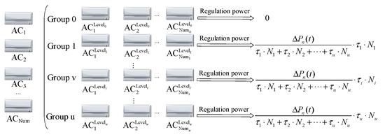
Figure 3.
The classification process of the ACs.
The regulation power can be expressed as follows:
where is the coefficient regulation power of Group i. is the ACs’ quantity of Group i.
5. Numerical Test and Results
The availability of the proposed voltage regulation strategy is verified in the IEEE 33 node power system, which is shown in Figure 4. Node 1 is the reference node. The others are the ‘PQ’ nodes. According to IEEE Recommended Practice for Monitoring Electric Power Quality, the voltage of each node should be kept within [0.9, 1.1] p.u. [17].
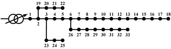
Figure 4.
The model of the IEEE 33 node power system.
The simulation lasts a whole day, from 6:00 a.m. on the first day to 6:00 a.m. on the second day, which has 288 time slots, with each time slot set as 5 min. The penetration rates of the PVs and the ACs are 85% and 100%, respectively. The data of PVs and base load are obtained from the literature [18], which is shown in Figure 5. The outpower of the PVs reaches the maximum of 7229.7 kW at 11:10 and stops generating power at 19:20. The load fluctuates around 4623.8 kW and 2325.9 kW. The parameters of the thermal model are shown in Table 1.
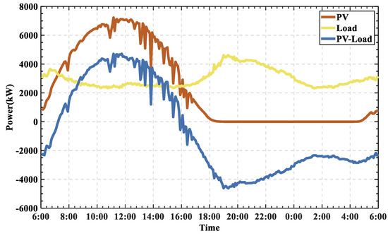
Figure 5.
The data of the PVs and loads.

Table 1.
Units for Magnetic Properties.
Three cases are considered in the simulation as follows:
Case 1: The voltage regulation is not applied.
Case 2: The voltage regulation is applied only with the OLTC.
Case 3: The voltage regulation is applied with the OLTC and ACs.
In Case 1, due to the unbalance power between supply and demand, the voltage problem happens without any voltage regulation. For Case 2, the OLTC provides voltage regulation when the nodal voltage exceeds the permissive range. For Case 3, the OLTC and the ACs participate in voltage regulation services when the nodal voltage exceeds the permissive range. The ACs exit voltage regulation after the action of the OLTC finishes.
5.1. Case 1: Without Voltage Regulation
The nodal voltage curves are shown in Figure 6. The red, blue, and green curves represent the voltage of nodes 18, 17, and 16 (having voltage problems), respectively. The grey curves of other nodes have had no voltage for the whole day. Since node 18 is farthest from the reference node, the voltage problem of node 18 is most severe. The voltage of node 18 reaches the maximum of 1.013 p.u. at 11:10 and reaches the minimum of 0.896 p.u. at 19:20.
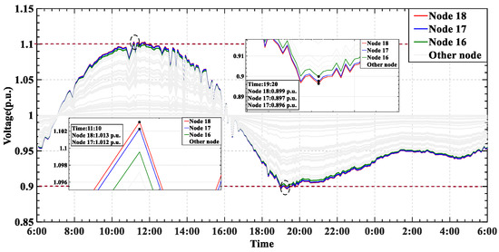
Figure 6.
The voltage curves before regulation.
5.2. Case 2: Voltage Regulation with OLTC
The OLTC is the traditional voltage regulation device that can effectively solve the voltage problem for the distribution network. The OLTC decreases the tap position, and the voltage of node 18 decreases from 1.103 p.u. to 1.091 p.u. at 11:11. The OLTC increases the tap position, and the voltage of node 18 increases from 0.897 p.u. to 0.911 p.u. at 18:41, the nodal voltage curves are shown in Figure 7. However, OLTC has a 1 min regulation delay time, so it cannot quickly respond to voltage problems.
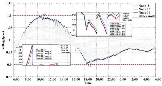
Figure 7.
The voltages curves after regulation by the OLTC.
5.3. Case 3: Voltage Regulation with OLTC and ACs
To solve the delay problem of the OLTC, the ACs will provide voltage regulation services during the delay time. At 11:10, the distribution network encounters the over-voltage problem. The ACs and the OLTC both participate in voltage regulation. The ACs in node 18 increase 58.46 kW operating power for over-voltage regulation. The four groups of the ACs increase 0 kW (Group 1: 0 ACs), 26.31 kW (Group 2: 50 ACs), 29.57 kW (Group 3: 47 ACs) and 2.58 kW (Group 4: 3 ACs) of operating power, respectively. The voltage of node 18 decreases to 1.099 p.u. After 1 min, the action of the OLTC finishes, the ACs exit voltage regulation, and the voltage of node 18 decease to 1.091 p.u. At 18:40, the distribution network encounters the under-voltage problem. The ACs and the OLTC both participate in voltage regulation. The ACs in node 18 decrease 37.31 kW operating power for under-voltage regulation. The four groups of the ACs decrease 0 kW (Group 1: 0 ACs), 0.24 kW (Group 2: 5 ACs), 13.81 kW (Group 3: 49 ACs) and 23.26 kW (Group 4: 46 ACs) of operating power, respectively. The voltage of node 18 increases to 0.900 p.u. After 1 min, the action of the OLTC finishes, and when the ACs exit voltage regulation, the voltage of node 18 increases to 0.911 p.u.. The nodal voltage curves are shown in Figure 8.
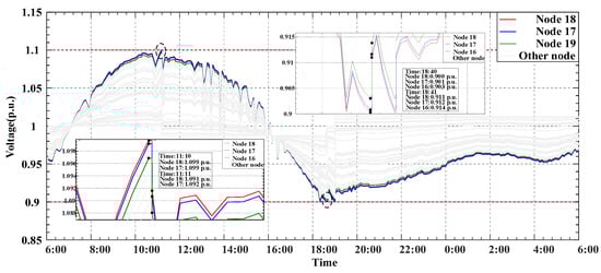
Figure 8.
The voltage curves after regulating by the OLTC and ACs.
6. Conclusions
The OLTC is an effective voltage regulation device, and the ACs have great potential for voltage regulation. Both of these have limitations in the process of voltage regulation. This paper proposes a novel voltage regulation strategy by coordinating the control of the OLTC and ACs to solve voltage problems of the distribution network. The ACs and the OLTC participate in voltage regulation when the distribution network encounters a voltage problem. The ACs provide a voltage regulation service before the action of the OLTC finishes and exits from regulating after the action finishes. The simulation test was carried out in the IEEE 33-node distribution system. The simulation results illustrate that the proposed voltage regulation strategy can provide fast responses for voltage regulation and optimize voltage problems.
Author Contributions
Conceptualization, H.Q.; methodology, H.Q.; software, J.C.; validation, J.C., Y.L. and L.Z.; formal analysis, Y.H.; investigation, H.Q.; resources, H.Q.; data curation, J.C.; writing—original draft preparation, J.C.; writing—review and editing, H.Q.; supervision, H.Q. All authors have read and agreed to the published version of the manuscript.
Funding
This paper is funded by the China Postdoctoral Science Foundation (2022M710039).
Conflicts of Interest
The authors declare no conflict of interest.
References
- Sanchis, P.; Lopez, J.; Ursua, A.; Marroyo, L. Electronic Controlled Device for the Analysis and Design of Photovoltaic Systems. IEEE Power Electron. Lett. 2005, 3, 57–62. [Google Scholar] [CrossRef]
- Varma, R.K.; Siavashi, E.M. Enhancement of Solar Farm Connectivity With Smart PV Inverter PV-STATCOM. IEEE Trans. Sustain. Energy 2019, 10, 1161–1171. [Google Scholar] [CrossRef]
- Ye, R.; Huang, X.; Chen, Z.; Ji, Z. A hybrid charging management strategy for solving the under-voltage problem caused by large-scale EV fast charging. Sustain. Energy Grids Netw. 2021, 27, 100508. [Google Scholar] [CrossRef]
- Mouli, G.R.C.; Bauer, P.; Wijekoon, T.; Panosyan, A.; Barthlein, E.-M. Design of a Power-Electronic-Assisted OLTC for Grid Voltage Regulation. IEEE Trans. Power Deliv. 2015, 30, 1086–1095. [Google Scholar] [CrossRef]
- Babaei, A.; Ziomek, W.; Gole, A.M. Transient characteristics of on-load tap changers during change-over operation. Electr. Power Syst. Res. 2021, 197, 107296. [Google Scholar] [CrossRef]
- Liu, J.; Li, Y.; Rehtanz, C.; Cao, Y.; Qiao, X.; Lin, G.; Song, Y.; Sun, C. An OLTC-inverter coordinated voltage regulation method for distribution network with high penetration of PV generations. Int. J. Electr. Power Energy Syst. 2019, 113, 991–1001. [Google Scholar] [CrossRef]
- Khan, H.A.; Zuhaib, M.; Rihan, M. Voltage fluctuation mitigation with coordinated OLTC and energy storage control in high PV penetrating distribution network. Electr. Power Syst. Res. 2022, 208, 107924. [Google Scholar] [CrossRef]
- Sun, X.; Qiu, J.; Yi, Y.; Tao, Y. Cost-Effective Coordinated Voltage Control in Active Distribution Networks with Photovoltaics and Mobile Energy Storage Systems. IEEE Trans. Sustain. Energy 2022, 13, 501–513. [Google Scholar] [CrossRef]
- Song, E.Y.; Fitz Patrick, G.J.; Lee, K.B.; Griffor, E. A Methodology for Modeling Interoperability of Smart Sensors in Smart Grids. IEEE Trans. Smart Grid 2022, 13, 555–563. [Google Scholar] [CrossRef]
- Manic, M.; Wijayasekara, D.; Amarasinghe, K.; Rodriguez-Andina, J.J. Building Energy Management Systems: The Age of Intelligent and Adaptive Buildings. IEEE Ind. Electron. Mag. 2016, 10, 25–39. [Google Scholar] [CrossRef]
- Hui, H.; Ding, Y.; Zheng, M. Equivalent Modeling of Inverter Air Conditioners for Providing Frequency Regulation Service. IEEE Trans. Ind. Electron. 2019, 66, 1413–1423. [Google Scholar] [CrossRef]
- Wang, D.; Meng, K.; Gao, X.; Qiu, J.; Lai, L.L.; Dong, Z.Y. Coordinated Dispatch of Virtual Energy Storage Systems in LV Grids for Voltage Regulation. IEEE Trans. Ind. Inform. 2018, 14, 2452–2462. [Google Scholar] [CrossRef]
- Meng, K.; The University of Sydney; Wang, D.; Dong, Z.; Guo, X.; Zheng, Y.; Wong, K.P.; The University of Newcastle; Grid, C.S.P. The University of Western Australia Distributed control of thermostatically controlled loads in distribution network with high penetration of solar PV. CSEE J. Power Energy Syst. 2017, 3, 53–62. [Google Scholar] [CrossRef]
- Lakeridou, M.; Ucci, M.; Marmot, A.; Ridley, I. The potential of increasing cooling set-points in air-conditioned offices in the UK. Appl. Energy 2012, 94, 338–348. [Google Scholar] [CrossRef]
- Morin, J.; Colas, F.; Dieulot, J.; Grenard, S.; Guillaud, X. Embedding OLTC nonlinearities in predictive Volt Var Control for active distribution networks. Electr. Power Syst. Res. 2017, 143, 225–234. [Google Scholar] [CrossRef]
- Hui, H.; Ding, Y.; Liu, W.; Lin, Y.; Song, Y. Operating reserve evaluation of aggregated air conditioners. Appl. Energy 2017, 196, 218–228. [Google Scholar] [CrossRef]
- Committee, E.M. IEEE Recommended Practice for Monitoring Electric Power Quality. IEEE Std. 2009, 2009, 6. [Google Scholar]
- Xie, Q.; Hara, R.; Kita, H.; Tanaka, E. Coordinated control of OLTC and multi-CEMSs for overvoltage prevention in power distribution system. IEEJ Trans. Electr. Electron. Eng. 2017, 12, 692–701. [Google Scholar] [CrossRef]
Publisher’s Note: MDPI stays neutral with regard to jurisdictional claims in published maps and institutional affiliations. |
© 2022 by the authors. Licensee MDPI, Basel, Switzerland. This article is an open access article distributed under the terms and conditions of the Creative Commons Attribution (CC BY) license (https://creativecommons.org/licenses/by/4.0/).