1. Introduction
With the development of renewable energy generation and energy storage technologies, isolated AC-DC converters become more and more attractive. Isolated AC-DC converters generally include two-stage AC-DC-DC structures [
1,
2,
3,
4,
5,
6] and single-stage ones. The two-stage structures possesses good performance, however, because of the large DC link capacitor, the power density and lifetime are difficult to increase [
7,
8,
9], which is the main disadvantage of this structure.
Over the past few years, single-phase isolated quasi-single-stage (Q1S) AC-DC converters without DC link electrolytic capacitors have been put forward [
10,
11,
12,
13]. Their front-end rectifier operates at the grid frequency, for which the switching loss can be ignored [
14]. Its back dual-active-bridge (DAB) converter can adopt an optimized phase shift modulation. In [
15], a triple-phase-shift (TPS) modulation strategy is proposed to extend the range of the soft-switching operation. A closed-form analytical solution for the modulation scheme of full-range zero-voltage-switching (ZVS) and near-minimum circulating currents is presented in [
16], which improves the efficiency and lifetime of the converter. Thanks to the efforts of researchers, this type of converter provides an effective solution to enhance the power density and efficiency and lengthen the lifetime of grid-connected power-conversion systems.
Since this type of converter needs to be generally connected to power grid, its quality of the grid current waveform ought to be ensured, otherwise the corresponding grid-connected standard cannot be reached. Based on its working principle, the voltage and current of the back-end DAB converter are processed in sinusoidal form, which illustrates that port voltage and average transfer current in a switching cycle are different from those in the contiguous cycle. Instantaneous transformer currents in any two contiguous switching cycles should be uncoupled and independently controlled so as to achieve the goal of average transfer current without steady-state error. In [
17], an improved triple-phase-shift (ITPS) modulation strategy is put forward, in order to completely eliminate circulating currents and coupling of transformer currents in the contiguous switching cycles, thus realizing the accurate control of AC side transfer currents. As a result, AC side currents of this converter are sine waves.
Under ideal conditions, namely, if the grid voltage waveform is sinusoidal without any harmonics, the grid current waveform will also be sinusoidal because the ITPS ensures a sinusoidal waveform of the AC side average current of the converter. However, an LC filter is set up between the converter and grid, which can transform converter’s AC side discrete currents to be continuous sine waveforms of grid currents. The LC filter introduces an impedance link between the grid and the converter, and as a result, the grid current is determined not only by AC side currents together but also by grid voltages. Since low-order harmonics are generally included in actual grid voltages, grid currents are difficult to ensure good sine waves, even though AC side currents of this converter are perfect sine waves. For the grid-connected type converters, the general solution to eliminate the influence of grid harmonics on grid currents is to construct the closed-loop control configuration of grid currents. In [
18], a ripple controller with improved voltage feed-forward scheme and quasi-proportional-resonant compensator was designed to realize good voltage ripple suppression for a Q1S AC–DC converter with an audio susceptibility model. A Q1S current-fed resonant AC-DC converter is proposed in [
19]. Its closed-loop control adopts a dual-loop structure, whose inner loop is used to control the grid current and the outer loop regulates the output voltage. A PI controller is used in both inner loop and outer loop. In [
20], a hybrid control strategy was proposed to realize stable output voltage and quasi-constant bus voltage, which consists of the output voltage feedback loop and the bus voltage feedback loop. However, the influence of the grid voltage harmonics on grid currents is not considered in [
18,
19,
20].
In order to eliminate the influence of the grid harmonics on grid currents of the Q1S AC-DC converter and fill in research gaps, in this paper, this problem is deeply researched and a grid current closed-loop control strategy for this converter is proposed. This paper has the following innovations and contributions. (1) The large-signal model of the Q1S AC-DC converter is built for the first time. (2) The influence of the grid voltage harmonics on grid currents is derived, which builds the theoretical basis for the upcoming solutions. (3) A novel grid current closed-loop control strategy is put forward by combining proportional-resonant (PR) controllers and odd-mode repetitive controllers (OMRC). The proposed closed-loop control strategy realizes the control of grid currents without steady-state error and eliminates the influence from grid voltage harmonics.
The rest of this paper is organized as follows.
Section 2 introduces the process of building the large-signal model of the Q1S AC-DC converter. In
Section 3, the influence of grid harmonics on grid currents is discussed based on the built model. In
Section 4, a novel compound grid current closed-loop control strategy containing a PR controller and an OMRC is proposed. Then, parameter constraints of the proposed compound controller are discussed.
Section 5 shows the experimental results. Finally, the conclusion is presented in
Section 6.
2. Large-Signal Model of Q1S AC-DC Converter
For the purpose of analyzing the influence of grid voltage low-order harmonics on grid currents, the large-signal model of the Q1S AC-DC converter under ITPS is built.
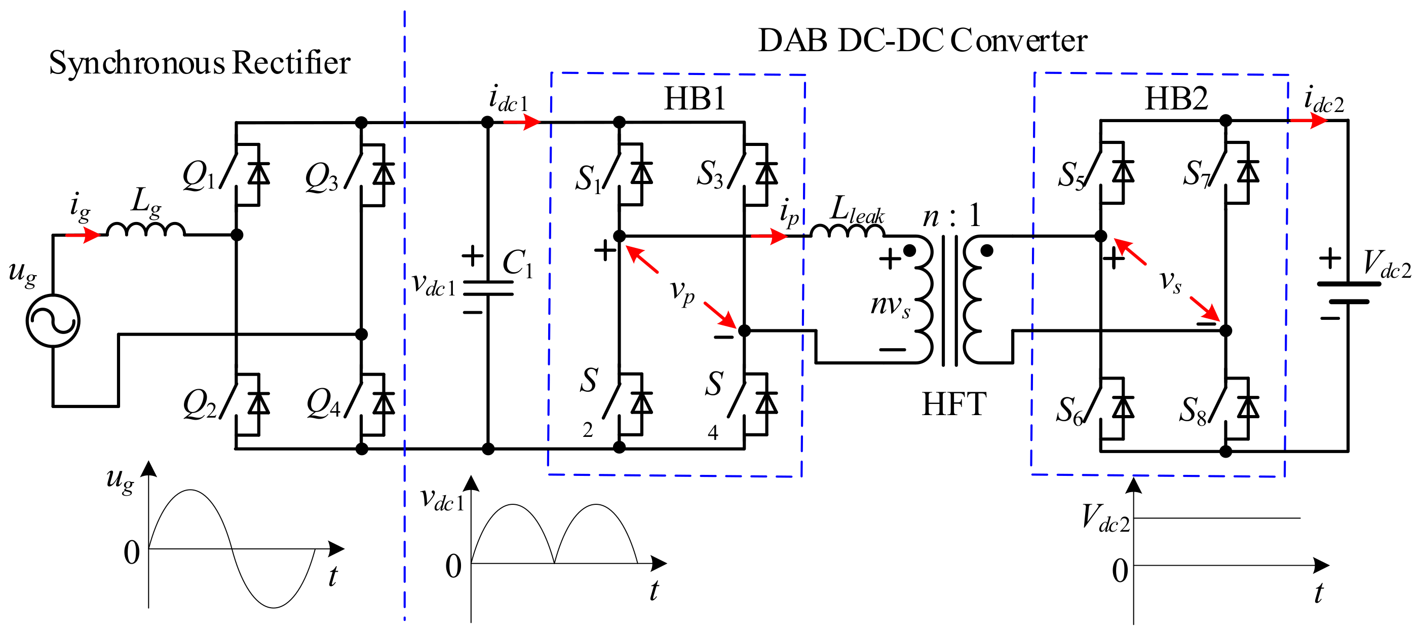
Figure 1 shows the topology structure of the Q1S AC-DC converter, which is comprised of the front-end synchronous rectifier and the back-end DAB converter. Its front-end synchronous rectifier converts the grid voltage to the unipolar rectified waveform. Comprised of the DC side capacitor
and AC side inductor
, the LC filter can filter out the high-frequency current components before they flow into the grid. Thus, the capacitance of
is generally very small and not exceeding tens of micro-Farad. HB1 and HB2 represent two H-bridge converters.
and
are the high-frequency voltages of HB1 and HB2.
and
are DC side voltages, and
and
are DC side currents.
represents the primary current of the high-frequency transformer (HFT). The turns ratio is
n. After the grid voltage is rectified, the unipolar voltage
can be acquired on
. The expression is shown as
In (1), and represent amplitude and frequency of the grid voltage.
For the purpose of keeping sinusoidal grid current
, the expected average DC side current of HB1 in the switching cycle
should be sinusoidal. As reported in [
17], its definition is
In (2),
is the expected AC side current amplitude of this converter. Since the grid frequency is far less than DAB converter’s switching frequency,
can be deemed a constant. Thus, at the switching cycle scale, the principle of the DAB converter put behind and exhibited in
Figure 1 identifies with the routine DAB DC-DC converter. Then this converter can realize the function of AC-DC buck-boost voltage conversion and bidirectional power flow. In [
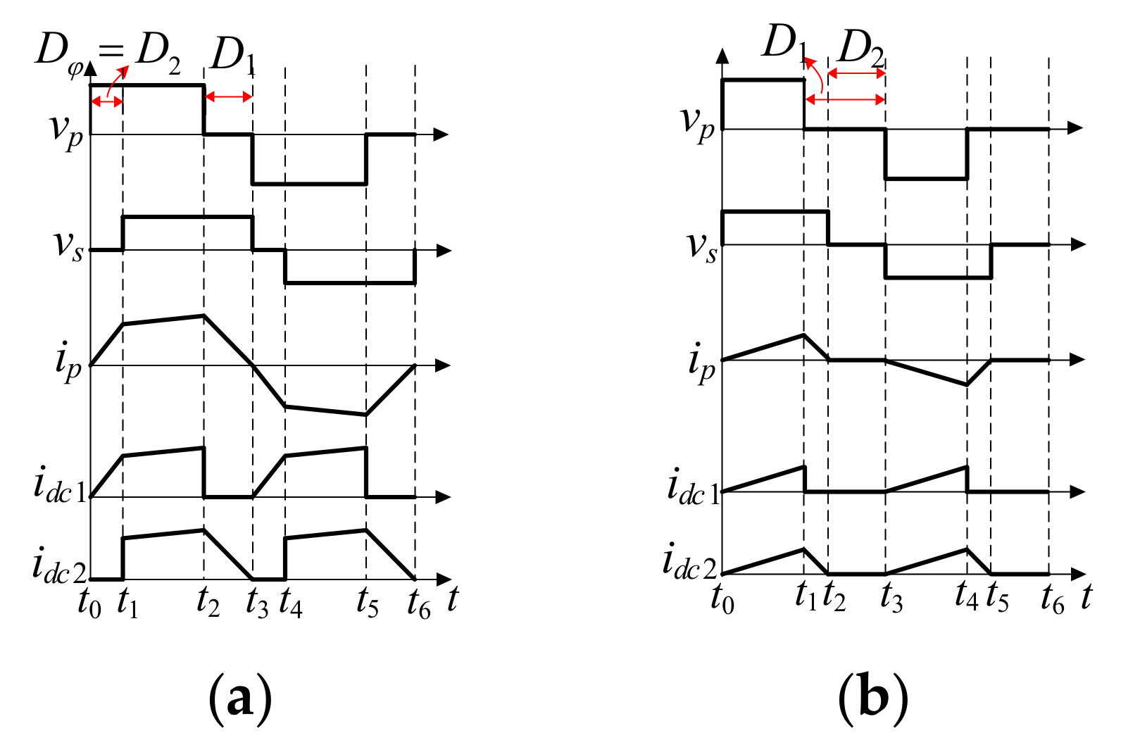
17], an ITPS modulation strategy is proposed to completely eliminate the circulating current and make transformer currents uncoupled in adjacent switching cycles, thus realizing the AC side transfer current’s accurate control of the converter. Switching period scale operating waves of the ITPS put forward in [
17] are shown in
Figure 2. In
Figure 2, the voltage conversion ratio is
,
.
and
represent the internal phase angles of HB1 and HB2, while
represents the outer phase shift angle.
From
Figure 2, transformer currents of the contiguous switching cycles are decoupled and waveforms of the positive half switching cycle and the negative half switching period are completely symmetrical. For the sake of the simplification, the large-signal model is derived based on the waveforms in the positive half switching period. From
Figure 1, the grid side filter inductor, capacitor, and transformer leakage inductor are energy-storage components in this converter. Therefore,
,
and are selected as the state variables for the large-signal model building of this converter.
Based on
Figure 1 and
Figure 2a, the state equation
during
is expressed as (3) in [
17].
By putting three phase shifts’ relationships of the ITPS in [
16] into (3), the variation rate of the average transformer current within a half switching cycle is
From
Figure 1 and
Figure 2a, the state equation of
during
is expressed as
The average value of (5) within a half switching cycle is
The state equation of
in the positive half switching cycle is acquired from
Figure 1:
rL in (7) is called the filter parasitic resistor of the filter inductor. On the basis of (4), (6), and (7), the large-signal model of the converter under the modulation in
Figure 2b is
Similarly, the large-signal model in the negative half grid cycle is derived as
In order to characterize (8) and (9) in a unified form, define the following variables.
From (8)–(10), the large-signal model of the Q1S AC-DC converter in the whole grid cycle is
From (11), it is obvious that the differential value of the average transformer current in a switching cycle is zero. This feature is very interesting, because under the ITPS, Lleak does not cause the transient process of the transformer current, and in consequence the total order number of the system decreases. It means even the step change of the three phase shift occurs, the transformer current will reach its final value immediately, and there is no transient process; therefore, the Q1S AC-DC converter under the ITPS is a linear system in essence.
From (11), the transfer functions from
to
and from
to
can be expressed as
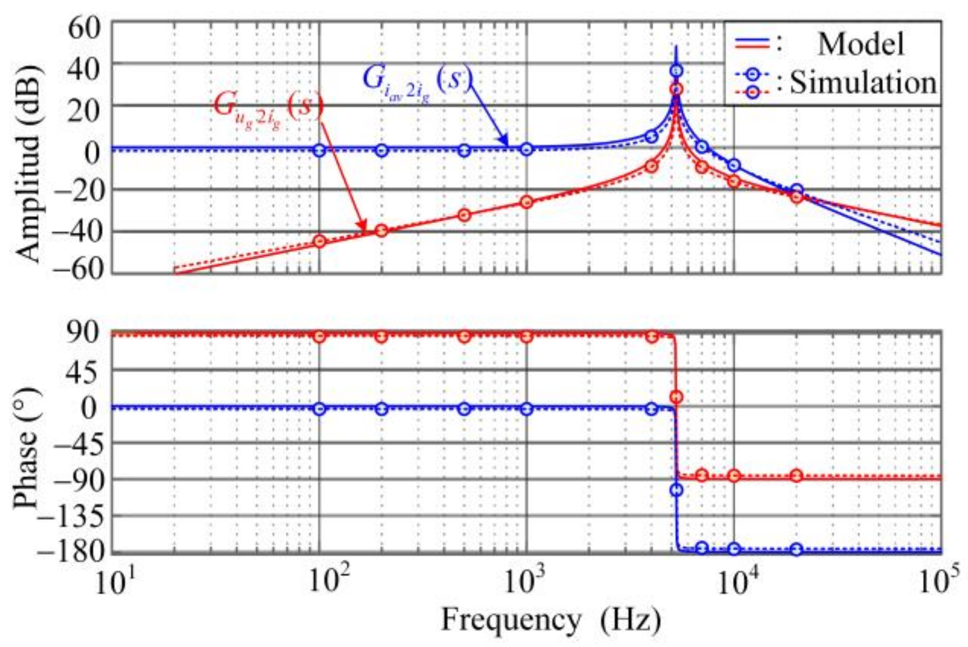
According to (12),
Figure 3 shows the bode diagrams of the built model, the simulation amplitude and phase data of the built model through the frequency-response method. From
Figure 3, the theoretical bode diagrams of the built model basically coincides with the simulation data, which proves the validity of the built model.
3. Influence of Grid Harmonics on Grid Currents
From
Figure 1, the actual grid currents are decided not only by grid voltages but also by AC side average currents of the converter. For this part, taking the low-order grid voltage harmonics into consideration, the influence of these harmonics on grid currents is researched based on the built model.
Based on the principle of ITPS in [
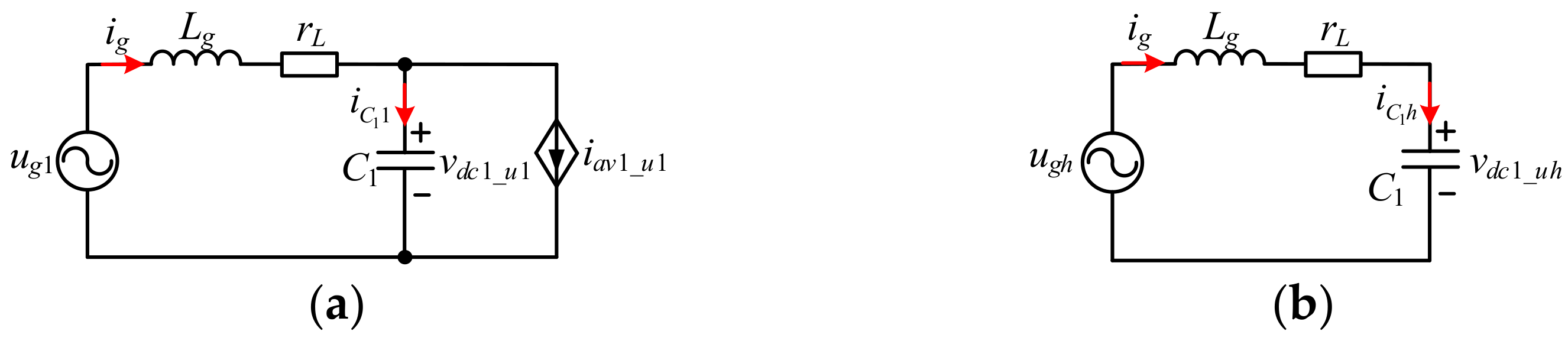
17], AC side currents of the converter are still sine shaped even if there are low-order harmonics in grid. From its large-signal model, the converter under the ITPS can be equivalent to a controlled current source
. Then when there are low-order harmonics in grid, the fundamental and harmonics equivalent circuits of this Q1S AC-DC converter are shown as
Figure 4a,b, respectively.
From the fundamental equivalent circuit in
Figure 4a, the relationship among various variables yields
From (13), the grid current fundamental component is
From the harmonics equivalent circuit in
Figure 4b, the grid current harmonics yield
From (14) and (15), the expression of the total grid current yields
From (16), is mainly determined by the currents of the converter AC side, while grid voltage low-order harmonics generate grid current harmonics, whose amplitudes are related to the LC filter parameters. The orders of those harmonics are consistent.
The effect of LC filter parameters on grid current low-order harmonics is analyzed as follows. For the parameter design of the LC filter, the ranges of the LC filter parameters should be comprehensively determined by the filter cutoff frequency, filter damping, and the power factor, and the specific parameters are finally determined according to the actual system operation performance [
21]. Hence, for a certain filter resonant frequency, there are a series of LC filter parameters to be selected.
Figure 5 shows the simulation waveforms of grid currents with two different groups of the filter inductance and capacitance, while with the same resonant frequency of 5 kHz. The simulation parameters of the converter are shown in
Table 1. The 3rd and 5th harmonics contents in the grid voltage are 10% and 5%, respectively, and the given grid current amplitude is 5A.
In
Figure 5, under two groups of LC filter parameters, the THDs of grid currents are all greater than 5% and the grid currents contain considerable 3rd and 5th harmonics. It follows that the grid voltage low-order harmonics will cause the same order grid current harmonics.
Figure 5 can also illustrate that only varying the parameters of the filter is not a highly efficient approach to eliminate the grid current harmonics caused by the grid harmonics. Therefore, for the purpose of eliminating the influence of grid harmonics on grid currents, it is necessary to research a new closed-loop control strategy of grid currents.
4. Proposed Grid Current Closed-Loop Control
For the purpose of improving the grid current’s performance and rejecting the effect of grid low-order harmonics, a general solution is to construct the closed-loop control system. The homologous closed-loop control configuration of grid currents of this converter is discussed first. Then the design of controller parameters is analyzed in detail in this section.
4.1. Grid Current Closed-Loop Control Configuration
To realize the control of the grid current fundamental component without steady error, the PR controller is utilized [
21]. Because the single-phase grid voltage generally contains odd harmonics, the odd harmonics will be caused in the grid current. The odd-mode repetitive controller (OMRC) contains the internal modes of all odd harmonics resonant controllers, so it can effectively eliminate the grid current odd harmonics [
22]. Besides, the needed data storage space of the OMRC is half the standard repetitive controller (RC), and its control error convergence period of the OMRC is also half the standard one [
23]. Then, a novel compound grid current closed-loop control strategy containing a PR controller and an OMRC is proposed.
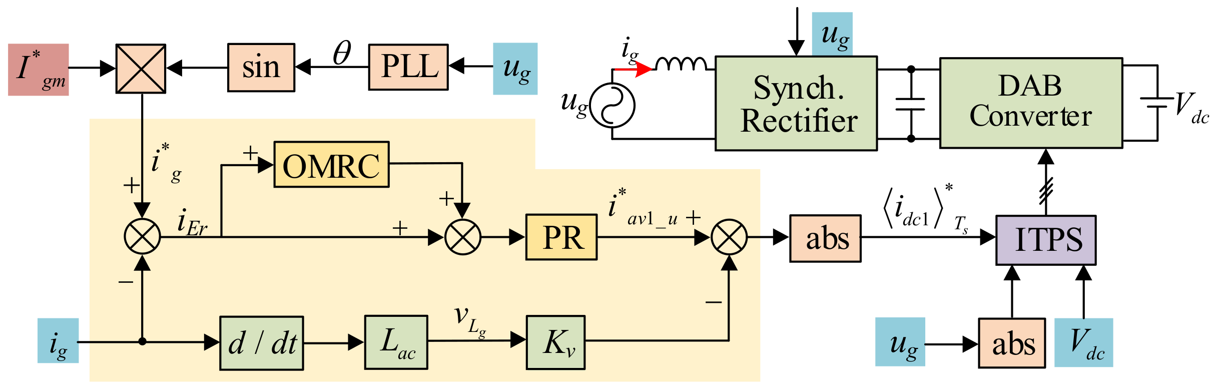
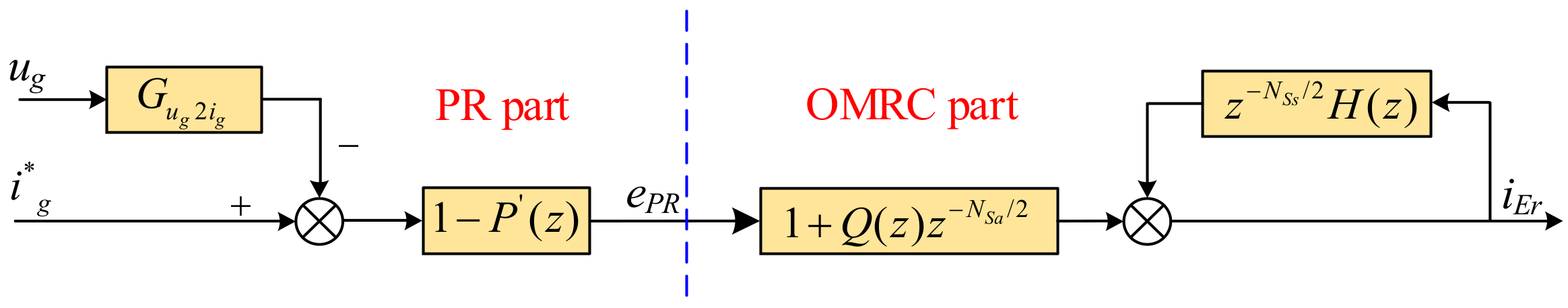
Figure 6 shows the configuration of the grid current closed-loop control strategy that is put forward. Variables with asterisk (*) are reference instructions. In
Figure 6,
is the amplitude of the grid current reference, which multiplies by the sine value of grid phase angle to gain the momentary grid current reference
. This grid phase angle is estimated online by the EPLL in [
24]. The difference between
and
,
is set to be the input of the OMRC. The sum of
and the OMRC output are set to be the input of the PR controller. Furthermore, the active damping method in [
25] is used to eliminate the resonance of LC filter. The inductor voltage is reconstructed by the differentiation of the acquired grid current to avoid adding an extra voltage sensor.
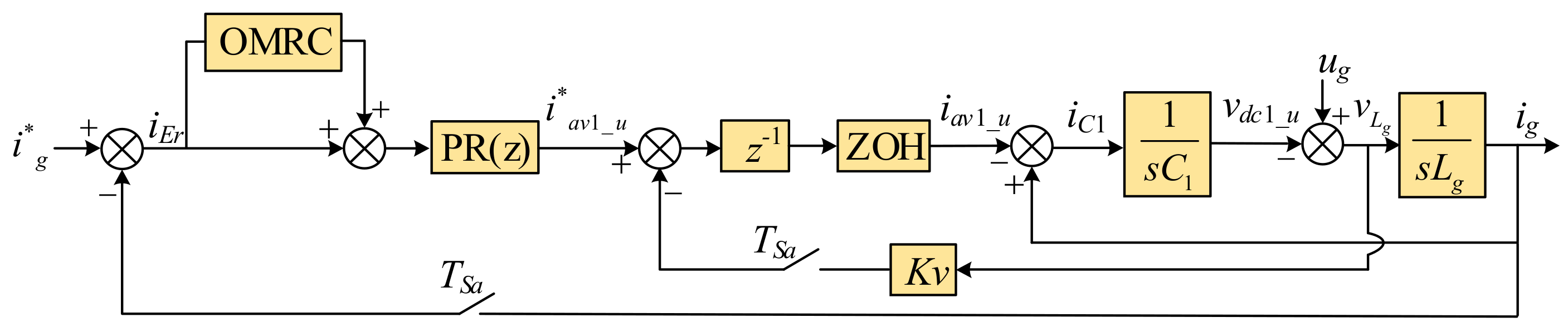
After the output of the PR controller deducts the feedback inductor voltage, the absolute value is set to be the AC side current reference of ITPS. Furthermore, the instantaneous grid voltage and the DC side voltage input ITPS, then the control signals of switching cycles are finally obtained. According to
Figure 6, the block diagram of the closed-loop system in the discrete domain is gained, just as shown in
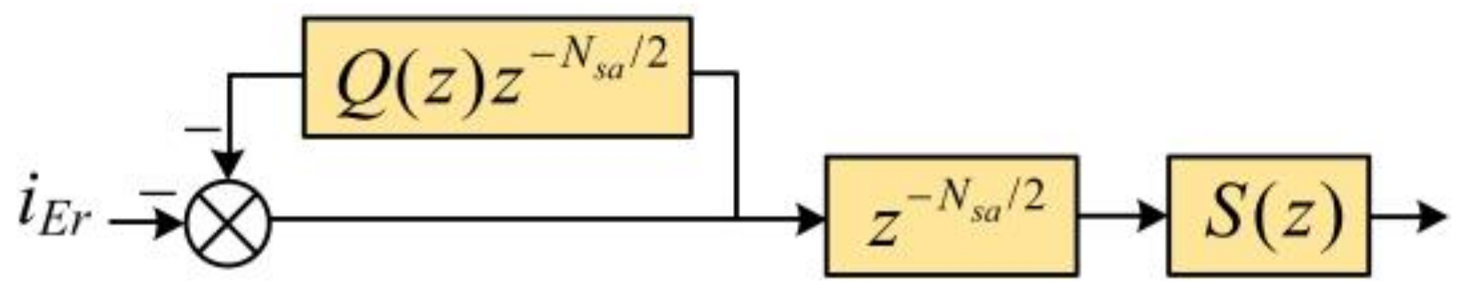
Figure 7. The corresponding configuration of the OMRC is shown in
Figure 8, in which
is the number of the data that should be stored in a grid period.
is the grid period and
is the sampling period. For the purpose of increasing this system stability, a LPF
and a compensator
are set.
From
Figure 8, the internal mode of OMRC is expressed as
Equation (17) in s domain can be expressed as
where
is the resonant cutoff frequency.
From (18), the OMRC contains the internal modes of all odd harmonics resonant controllers, so it is able to effectively eliminate the odd harmonics.
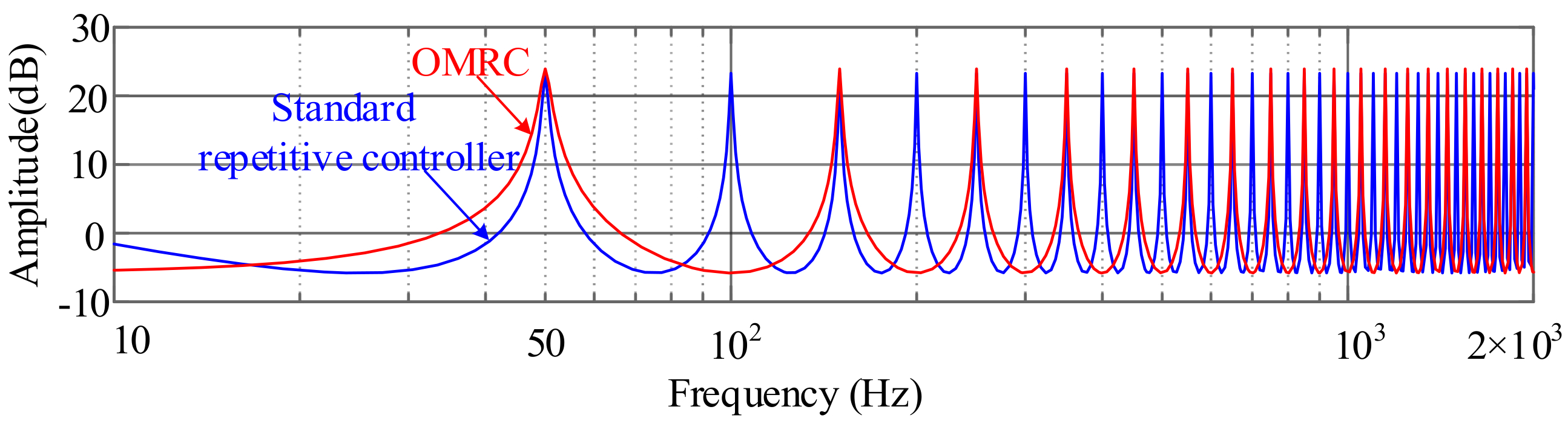
Figure 9 shows the curve of the OMRC’s amplitude-frequency characteristics, which can be gained on the basis of (18). According to
Figure 9, the OMRC presents the high gains in odd harmonic frequencies and accordingly, the effect of odd-order grid harmonics can be eliminated.
4.2. Parameter Constraints of Proposed Compound Controller
Next, the parameter constraint of this proposed PR + OMRC control strategy is analyzed in this section, in order to build the theoretical reference for the controller parameter design.
The stability constraint is analyzed first.
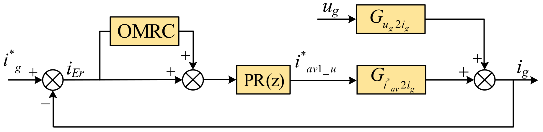
Figure 10 shows the simplified block diagram of the PR + OMRC, where the grid voltage is regarded as the disturbance. From
Figure 10, the function expression of the grid current control error is
where
is the system closed-loop transfer function only under PR controller. Then the block diagram of the grid current control error is obtained from (19) and shown in
Figure 11, where
.
According to
Figure 11, the grid current control error contains two parts, namely, it can be regarded as the sum of the two current control errors under only one controller, which are defined as
and
, respectively. In order to realize the global stability of the closed-loop system with the proposed compound controller, it is necessary to ensure
and
both converge. Therefore, the characteristic roots of the equivalent two closed-loop systems only under the PR controller and only under the OMRC should all be located within the unit circle of
z plane:
Next, the convergence constraints of the controller are analyzed. The major goal of this compound controller is to eliminate odd grid current’s harmonics of caused by grid harmonics. From
Figure 11, it yields
Furthermore, (21) can be organized as
Angular frequency of grid current odd harmonics is
From (23), at the odd harmonics frequencies,
is
By substituting (24) into (22) and considering that
is closed to 1 in the low frequency bands, there is
According to (25), the update cycle of this proposed controller is 1/2T1. As a result, the control error convergence rate is twice that of the standard repetitive controller.
Last, the zero steady-state error constraint is derived. By substituting (24) into (21), there is
From (26), the control error of the current odd harmonics is reduced by times. Therefore, in order to eliminate the odd harmonic currents, namely, to ensure , it is necessary to set , .
4.3. C. Parameter Design of Proposed Compound Controller
According to the above analysis, the parameters of PR and OMRC can be designed separately. The parameter design of the PR controller is first. From
Figure 7, the discrete-domain open-loop transfer function of Q1S AC-DC converter is expressed as
In (27), , , .
In [
21], the PR controller’s parameter design has been discussed in detail and it is not mentioned here.
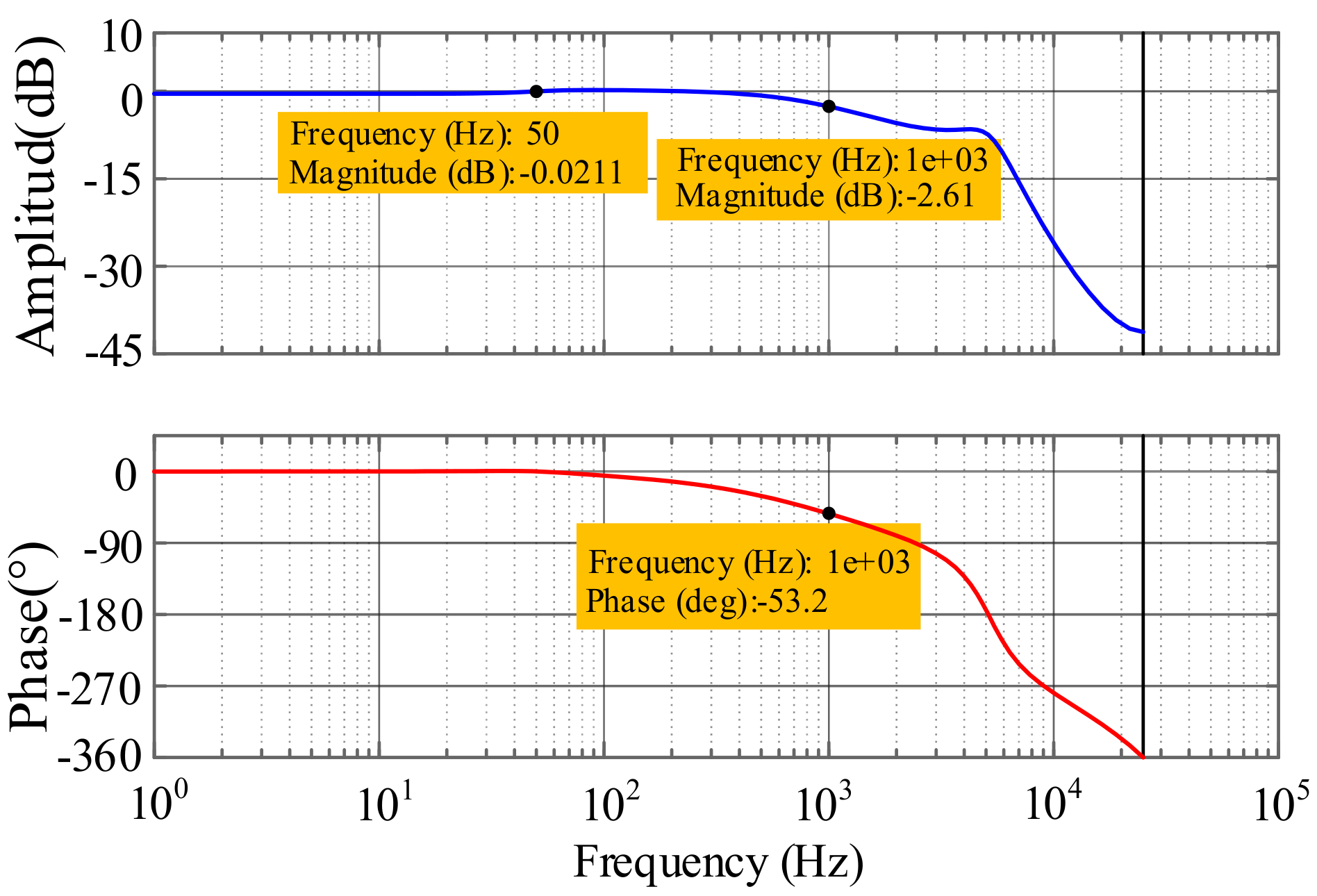
Table 2 lists the resulted parameter values. The bode diagram of the closed-loop system with the PR controller
drawn and shown in
Figure 12. At grid frequency, characteristics of
are unit gain and zero phase shift. Therefore, the control of grid current first harmonic without steady-state error can be achieved.
The parameters design procedure of OMRC is introduced as follows. The sampling frequency is the same as the switching frequency:
. An LPF without phase shift is used for
and its expression is
The general expression of compensator
is
where
is the gain factor of the compensator,
is the phase lead link, and
is the low-pass filter.
From
Figure 12, in the low-frequency bands, the gain of
is unity, therefore,
and
are determined. Since there is the phase lag in
, the phase lead link
should be used. From
Figure 12, the lag phase of
at 1 kHz is
. Therefore, phase advance factor
is
From (30),
contains the fractional part and it will decrease the actual phase compensation performance. In order to solve this problem, the finite-impulse response filter is utilized to approximate
[
26]. The final expression of
in the discrete domain is
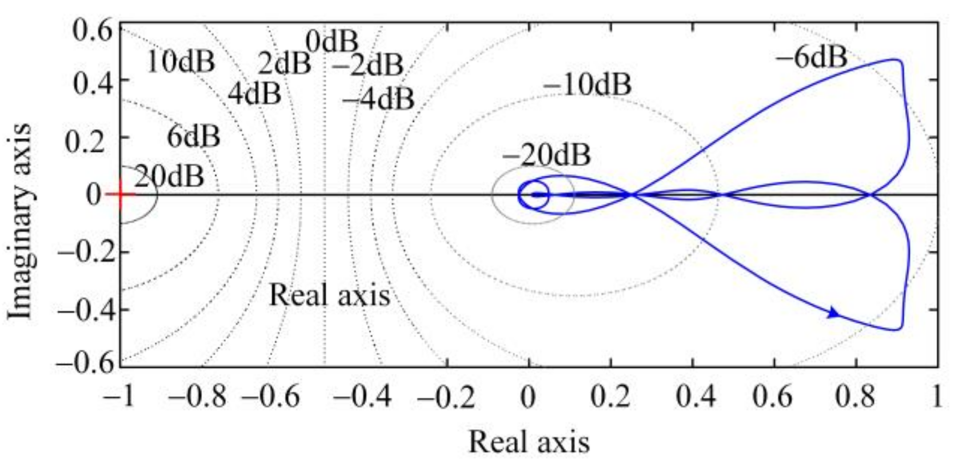
Based on these determined parameters, the Nyquist curve of
is drawn and shown in
Figure 13. From
Figure 13,
is always less than 1 in the entire frequency range. In consequence, the designed closed-loop system is globally stable.
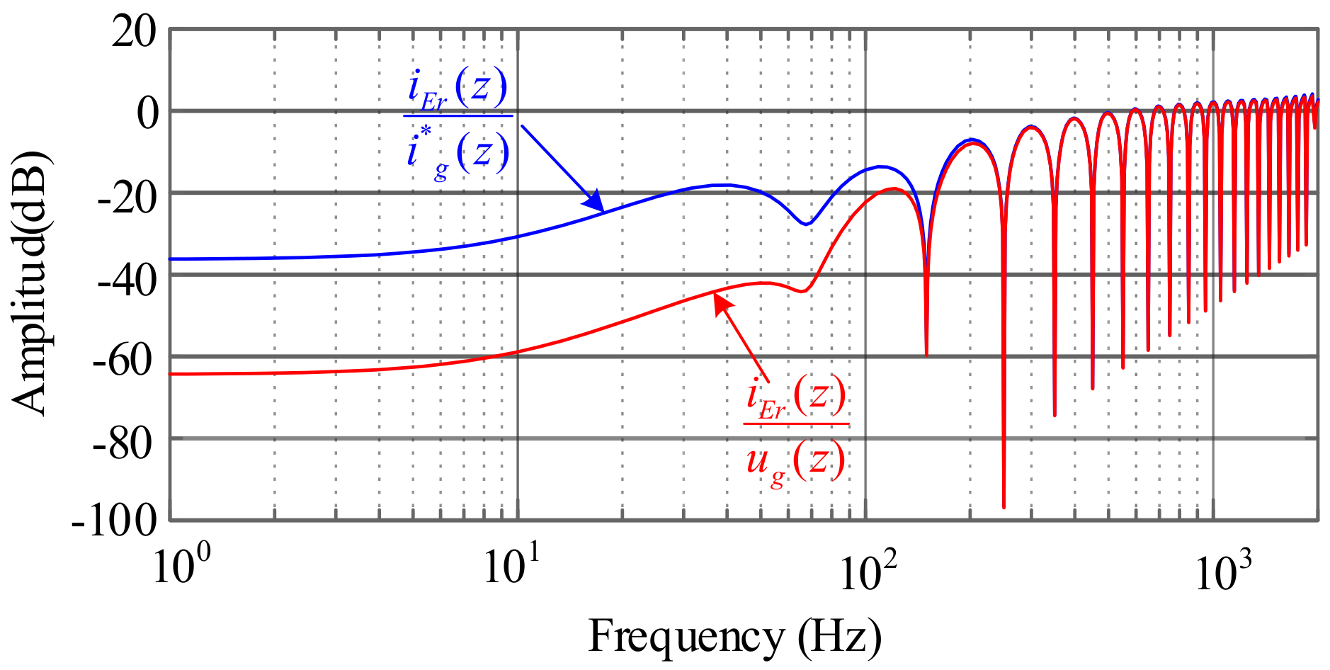
Figure 14 shows the bode diagram of the control error transfer function of the PR + OMRC. From
Figure 14, the tracking error of grid current at fundamental frequency is far less than 0 dB. It means that the zero steady-state error grid current control can be achieved. Furthermore, tracking errors of grid current at the odd-order frequencies are also far less than 0 dB. It means that the influence of grid voltage odd harmonics on grid current can be efficiently eliminated by the proposed compound controller.
5. Experimental Verification
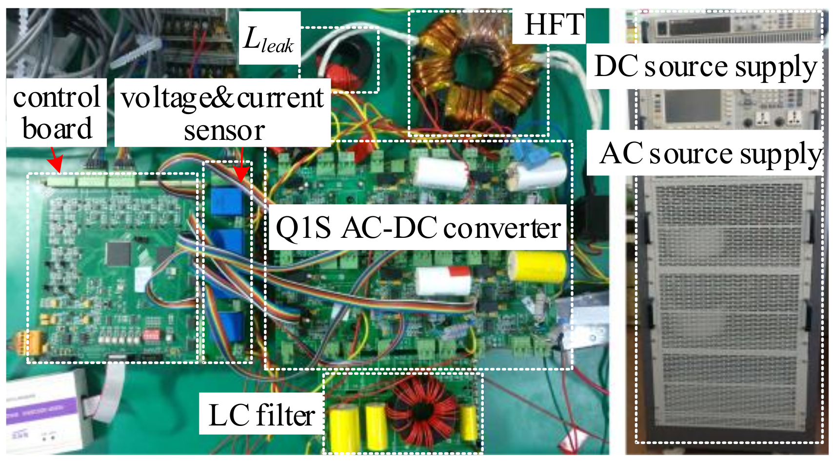
For the purpose of verifying the analysis of the effect of grid harmonics and proposed closed-loop control strategy, the experiment platform of this Q1S AC-DC converter has been built.
Figure 15 clearly shows its photograph. The corresponding experimental parameters are the same as
Table 1 and
Table 2. We inject 10% of the 3rd, 5% of the 5th and 7th harmonics to output voltage of AC source supply, with the aim to realize the simulation of the distorted single-phase grid voltage. All of these experimental results are measured by Memory Hicorder MR6000 from HIOKI (Ueda, Japan).
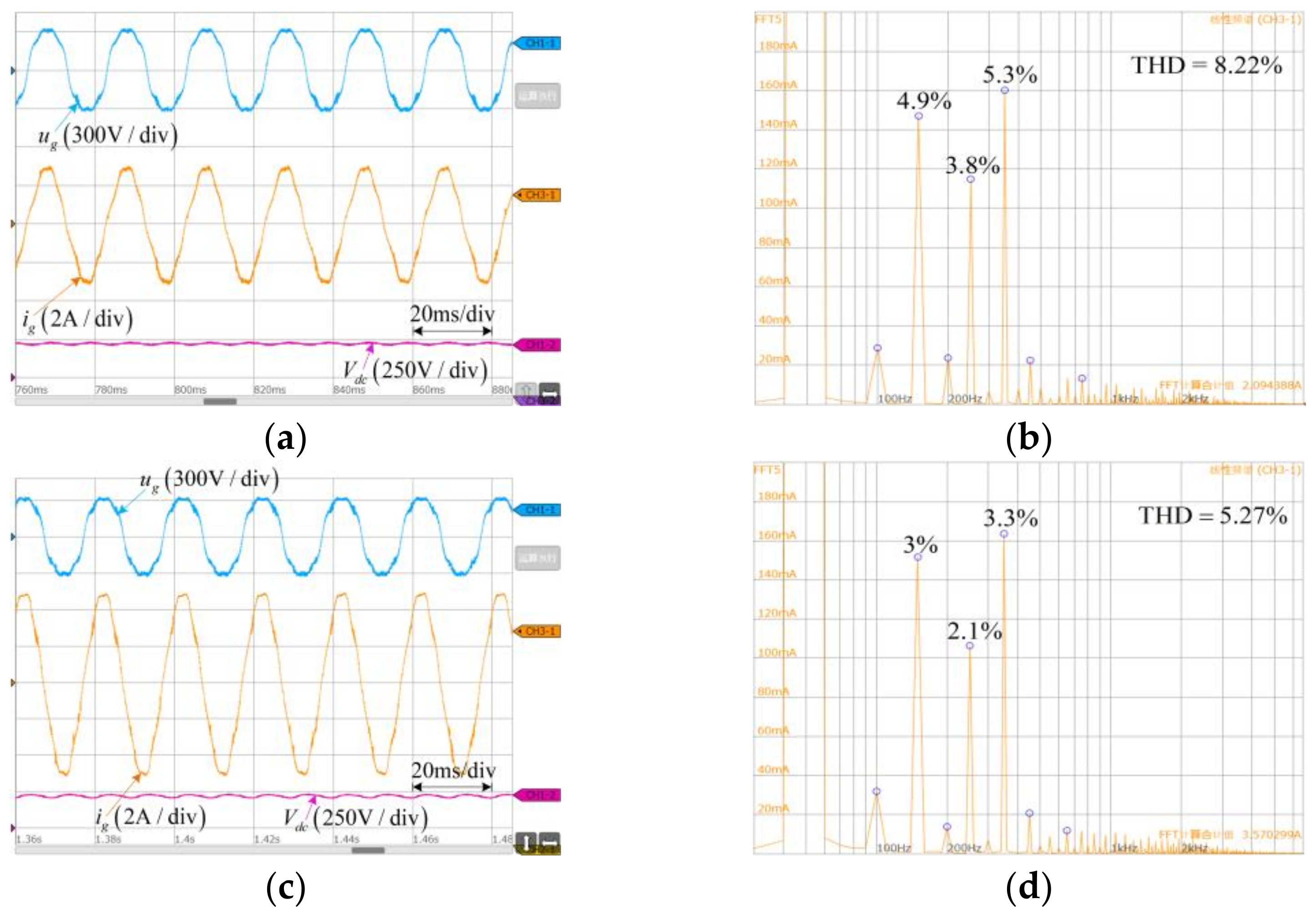
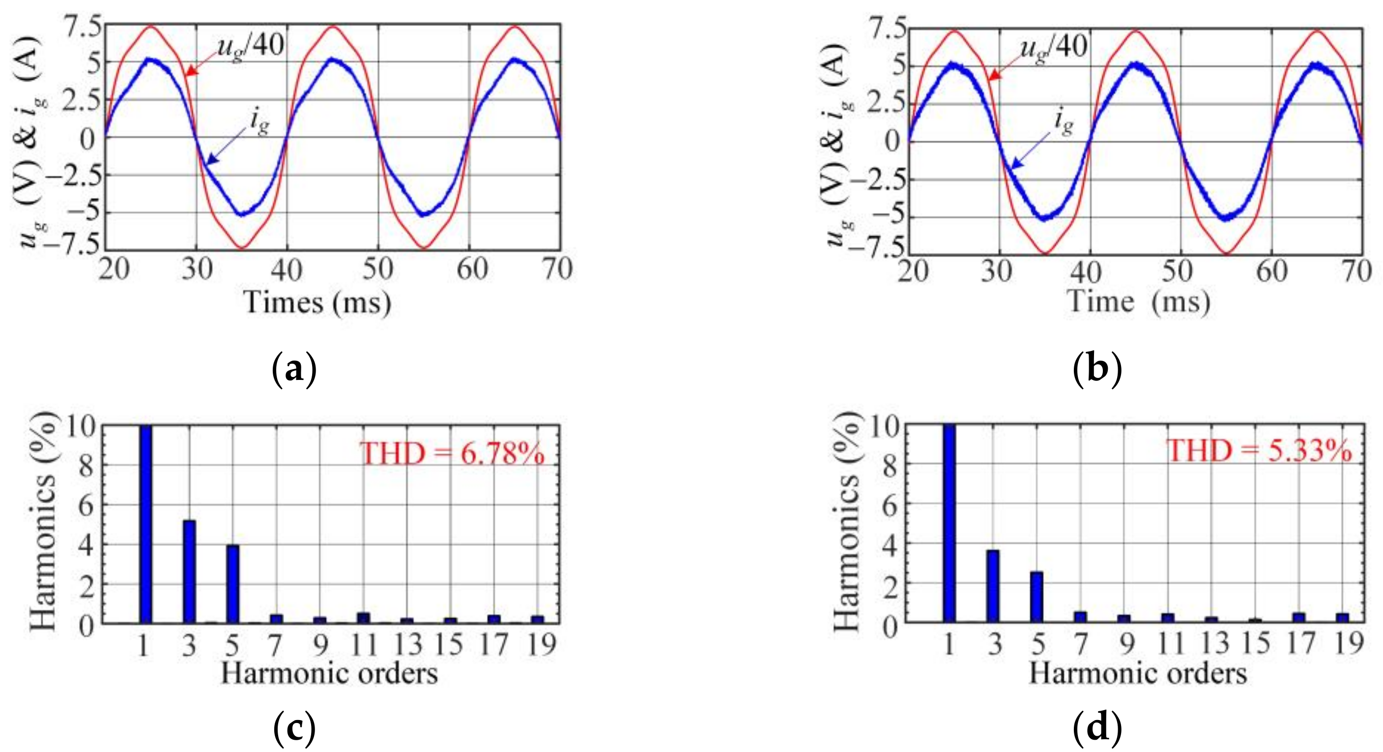
First, the influence of grid harmonics on grid current of this converter driven by ITPS control under open-loop situations is verified, as displayed in
Figure 16. From
Figure 16a,c, when given grid current amplitudes are 3A and 5A, respectively, obvious distortions of grid currents can be seen. From
Figure 16b,d, under two different current amplitudes, 3rd, 5th, and 7th current harmonics obviously exist and THDs of grid currents are 8.22% and 5.27%, respectively. This verifies that the grid harmonics do cause the same order harmonics in the grid currents. In consequence, the validity of previous theoretical analysis is verified.
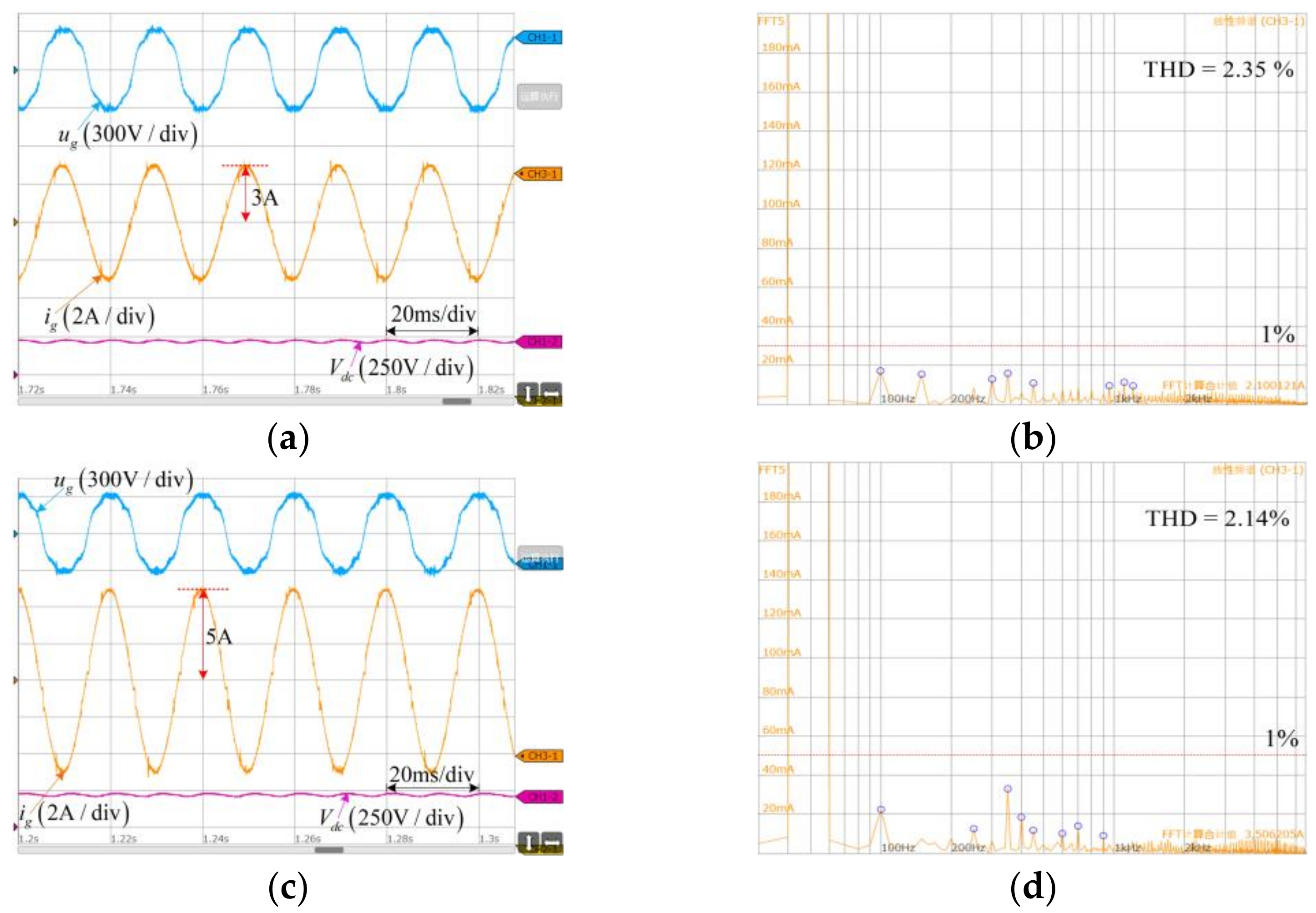
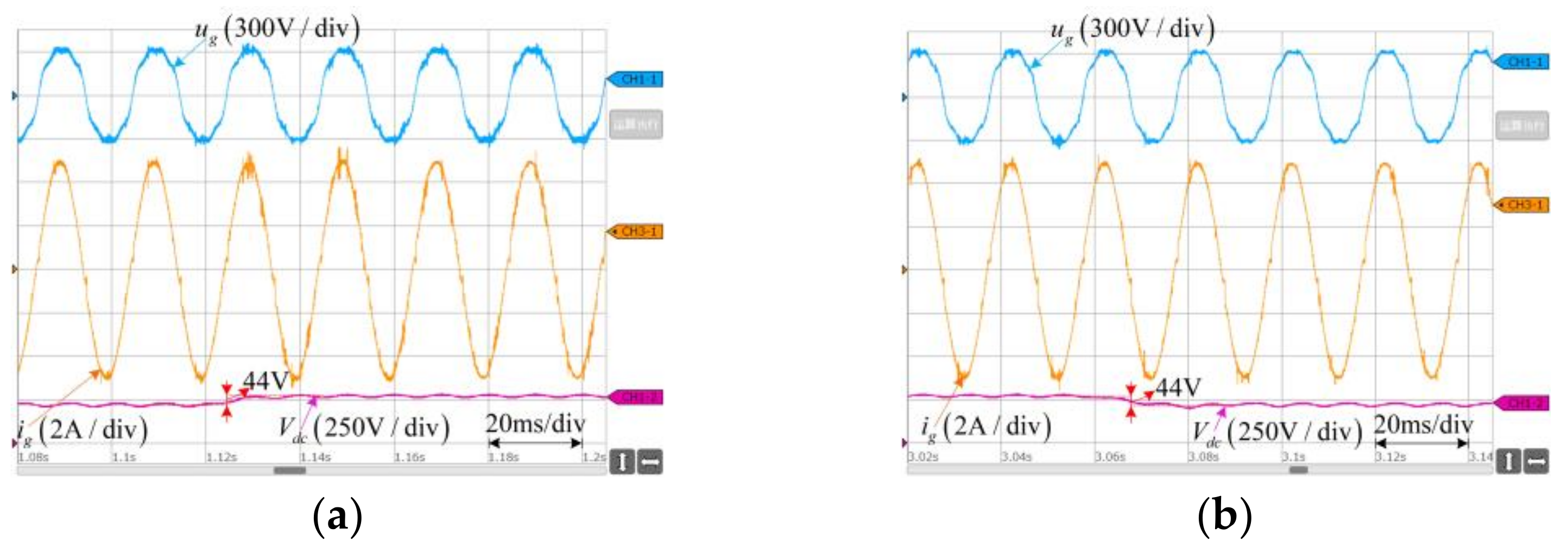
In the following, the steady-state control performance of the compound closed-loop control strategy that we put forward is verified. Grid voltage and given grid current amplitude are the same as that under open-loop situations.
Figure 17 shows relevant experiment results in detail. According to
Figure 17a,c, under two given different grid current amplitudes, the actual grid currents are both sine waves, whose amplitudes are precisely 3A and 5A. It verifies that the closed-loop control strategy put forward realizes the function that control of grid current fundamental component is without steady-state error.
From
Figure 17b,d, THDs of grid currents are 2.35% and 2.14%, respectively, and the 3rd, 5th, and 7th harmonic contents are all reduced below 1% under these two situations. Therefore, the proposed closed-loop control strategy effectively eliminates the grid current odd harmonics.
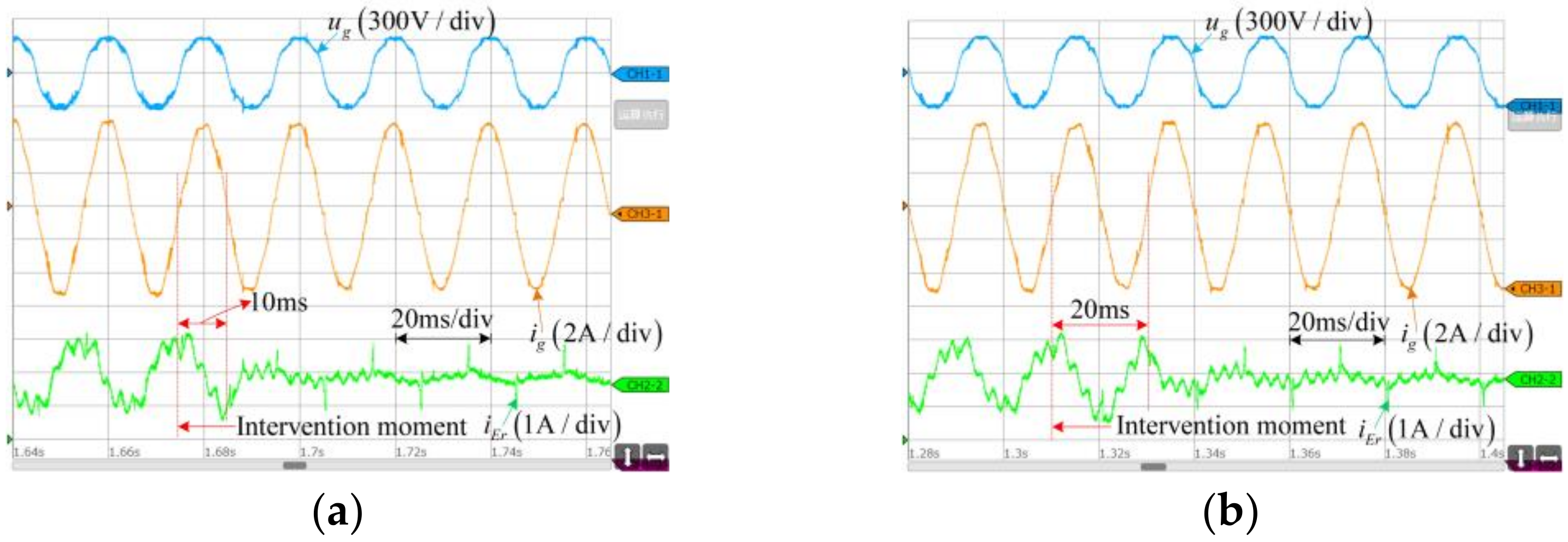
For the purpose of verifying the control error convergence rate of OMRC that we put forward,
Figure 18 shows the respective experiment results when proposed OMRC controller and another standard RC are suddenly enabled. From
Figure 18, before the two controllers are enabled, there is a periodic ripple in
iEr and the grid current is distorted.
After either OMRC or RC is enabled, iEr reduces to zero gradually. The difference is that after OMRC is enabled, iEr reduces to zero within 1/2 grid period; however, after the standard RC is enabled, iEr reduces to zero within one grid period. Hence, it verifies the convergence speed of the OMRC is twice that of the standard RC.
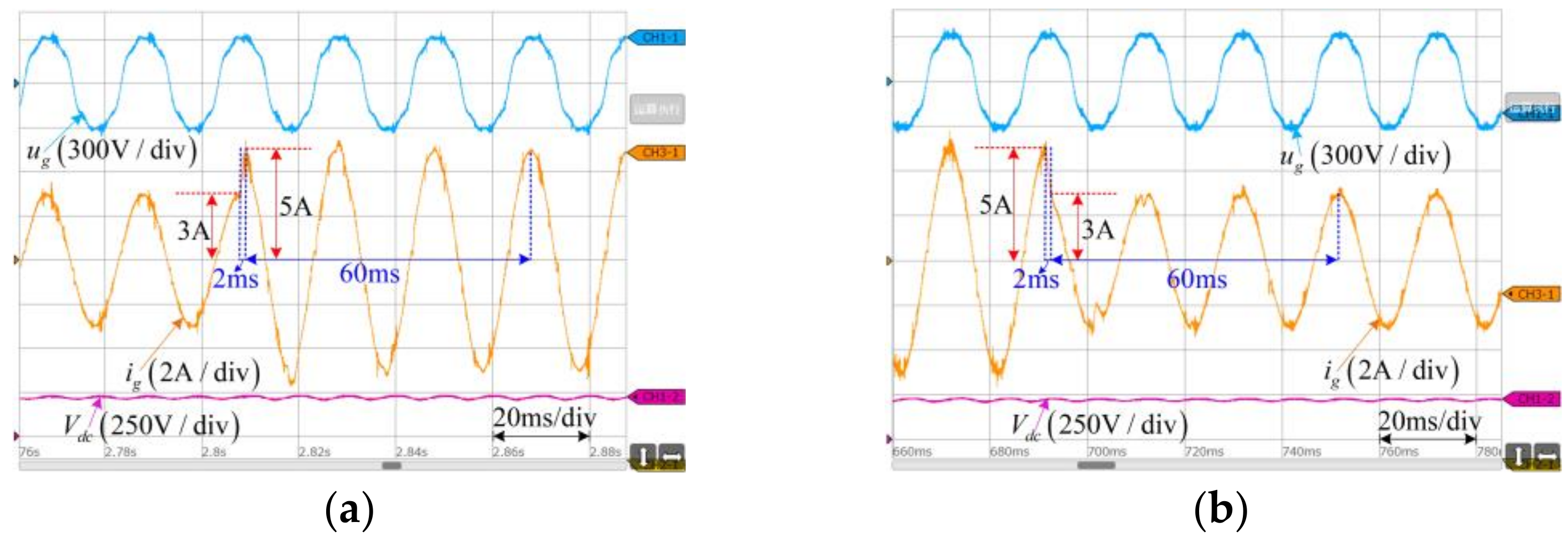
Next, the dynamic performance of the proposed compound controller is verified in
Figure 19. In
Figure 19a, when the reference grid current steps up from 3A to 5A, the actual grid current amplitude can be adjusted to the given value within 2 ms. After around 60 ms (three grid periods), an undistorted sinusoidal grid current is obtained.
Figure 19b shows the situation that the reference grid current steps down from 5A to 3A. Its dynamic process is similar to
Figure 19a. Therefore,
Figure 19 certifies that the proposed controller realizes good dynamic performance.
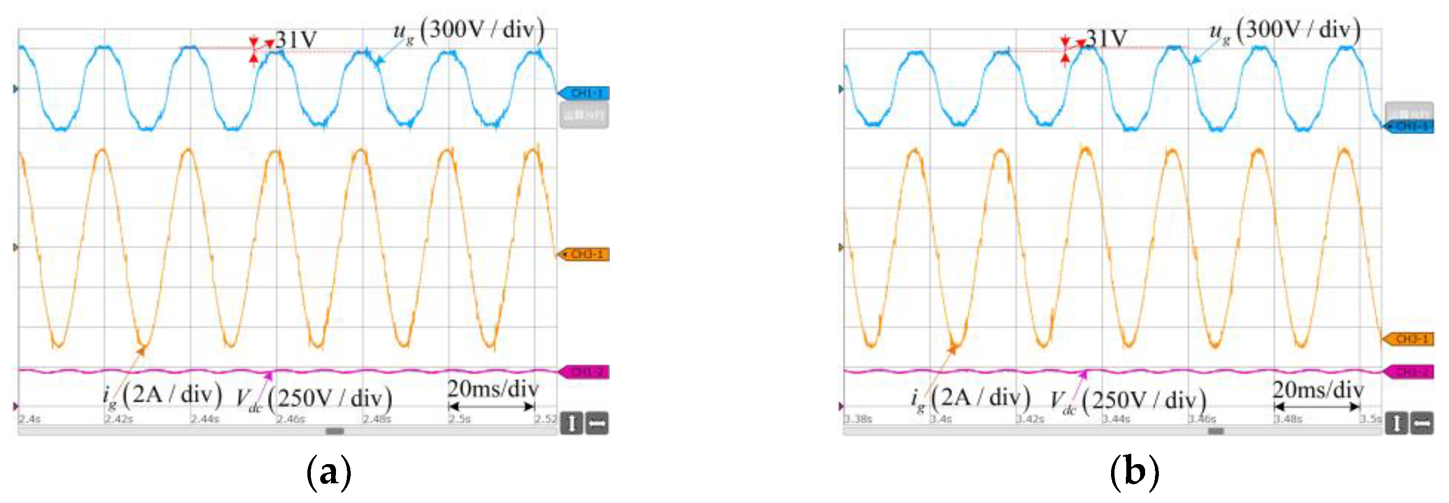
Finally, the ability of the proposed strategy to reject the step disturbance of AC or DC sources is verified. From
Figure 20, when the grid voltage amplitude floats up or down by 10%, the grid current amplitude maintains constant. Meanwhile, its transient adjustment process is very short. From
Figure 21, when DC side voltage floats up or down by 20%, the grid current amplitude also maintains constant. Meanwhile, its transient adjustment process is also very short.
Figure 20 and
Figure 1 verify that the compound controller we put forward efficiently eliminate the effect of step disturbance of grid voltage and DC side voltage.


