1. Introduction
Electric and hybrid vehicles use three times more motors than fossil-fueled vehicles [
1,
2]. The use of so many motors increases the weight of vehicles and their fuel consumption. To solve this problem, the ferrite magnets used in the motors should be replaced with Nd
2Fe
14B permanent magnets with superior magnetic characteristics to reduce the weight of the motors and improve overall fuel efficiency [
3,
4,
5]. Nd
2Fe
14B permanent magnets have been recognized as the most energy-efficient hard magnets with excellent magnetic properties. Nd
2Fe
14B-based permanent magnets have been intensively studied due to their strategic importance for modern economies; these magnets are key components in sustainable mobility and energy conversion devices [
6]. The Nd
2Fe
14B phase crystallizes in a tetragonal structure with space group P42/mnm. Nd
2Fe
14B ternary magnets exhibit excellent magnetic properties since they can be produced in fine crystalline grains (ca. 0.3 µm), close to a single domain size, using the hydrogenation–disproportionation–desorption–recombination (HDDR) process [
7], which was first reported by Takeshita and Nakayama [
8]. Permanent magnets used in motors must be magnetized to uniformly create flux in 4 to 24 poles for uniform motor torque. If non-uniform flux is emitted from the yoke and the permanent magnets are non-uniformly magnetized, an unstable flux is emitted from the permanent magnets that are magnetized when the motor is driven. Such non-uniform magnetic flux emission causes an unstable rotation when the motor is driven, which results in noise and deterioration in the motor performance [
9,
10]. Therefore, in this study, various magnetic yokes were designed and fabricated to analyze the magnetic characteristics of the permanent magnets in order to understand the factors that are related to the non-uniform rotation of the motor. A permanent magnet magnetized in each condition was mounted on a rotor to manufacture a motor, and the performance of the motor was evaluated. Finally, we propose an optimal yoke design for improving motor performance.
2. Experimental Procedure
2.1. Materials
As a raw material, we used Nd
2Fe
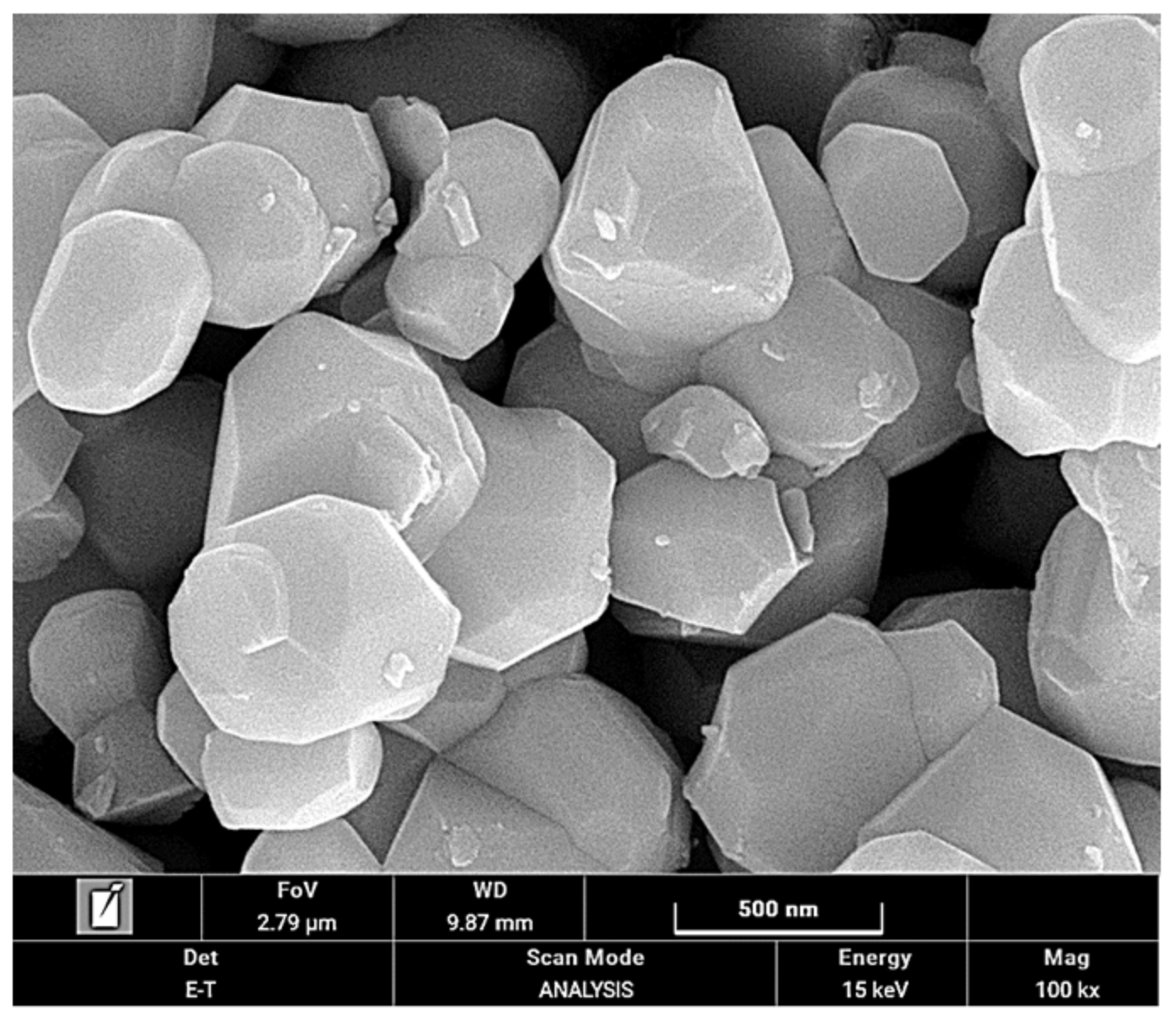
14B powders with high residual inductance (9.15–9.35 kG) and low intrinsic coercivity (6.8–7.8 kOe), which were fabricated by employing a proprietary rapid solidification process followed by a milling process and heat treatment. Microstructures of specimens were examined with scanning electron microscopy (SEM).
Figure 1 shows an SEM image of the Nd
2Fe
14B powders. The Nd
2Fe
14B powders have an irregular shape with an average particle size of approximately 500 nm.
Nd2Fe14B powders and epoxy resin were mixed manually, to which was added a hardener weighing approximately 0.5% of the epoxy resin. The mixed materials were pressed with an applied pressure of ~5 MPa, and we obtained a disk sample with diameter of 10 mm and thickness 7 mm. The pellet samples were cured using a drying oven at 200 °C.
A magnetometric study of Nd2Fe14B bonded magnets was performed. The magnetic properties of Nd2Fe14B had a strong temperature dependence. The (BH) max drops sharply once the temperature exceeds 100 °C. In order to achieve saturation magnetization, the power conditions of the magnetizing yoke were set to 950 V and 800 uF to generate 1.4 Tesla magnetic fields at room temperature. A magnetized yoke was designed to emit various magnetic fluxes.
Case 1: The center of the magnetization yoke core and the winding coil coincided with one another.
Case 2: The center of the yoke core and the winding coil matched, but the center of the wound coil had a 100 μm deviation.
Case 3: The center of the winding coil was shifted by 50 μm from the center of the yoke core.
Nd
2Fe
14B bonded magnets with 100 ea were magnetized with a magnetized yoke to produce each condition. Each of the magnetized Nd
2Fe
14B magnets was used to manufacture a motor. The magnetized yoke was analyzed through a non-destructive analysis procedure. Additionally, magnetic properties of the magnetized yoke and magnetized magnet were analyzed using a surface flux meter. The motor was fabricated using the magnets magnetized with the respective magnetizing yokes, and the correlation between the magnetizing yoke and the motor characteristics was analyzed.
Figure 2 shows the schematics of motor assays and tear-down images of motor indicating stator and rotor (Nd
2Fe
14B bonded magnets).
2.2. Testing Procedures
In this study, three designs of magnetization yokes were proposed to confirm the influence of the magnetic flux emitted from the yoke at the time of magnetization. Based on the three designs, the magnetization yoke was manufactured. The manufactured magnetization yoke was connected to the magnetizing power supply, and magnetization was performed under the conditions of 1500 V and 2000 uF.
The magnetized magnets were evaluated to determine their magnetization characteristics using a surface flux meter. Moreover, after the magnetized magnet was mounted on the motor and driven, total harmonic distortion analysis (THD) and back electromotive force (BEMF) were evaluated, respectively.
3. Results and Discussion
Figure 3 shows microstructures of the Nd
2Fe
14B bonded magnets fabricated in this research. The polished microstructures (
Figure 3a,b) of the Nd
2Fe
14B bonded magnets show Nd
2Fe
14B particles uniformly and densely dispersed in the sample. The observed powder size from SEM images was approximately 500 μm.
In order to confirm the influence of the magnetic flux emitted from the yoke at the time of magnetization, three kinds of magnetization yokes (cases 1 to 3) were designed and are shown in
Figure 4. In case 1, the center of the yoke core and the center of the coil were designed to be the same and are shown in
Figure 4a. In order to confirm the effect of the magnetizing coil that emits the magnetic field at the time of magnetization, the center of the yoke core and the coil were designed to be the same, and the center of each coil was designed to have a deviation of 100 μm in the radial direction. This condition is shown in
Figure 4b. For case 3, the center of the coil was designed to have a deviation of 50 μm from the center of the yoke core and is shown in
Figure 4c.
The designed yokes were fabricated and then subjected to 3D non-destructive analysis with an X-ray, as shown in
Figure 5. In case 1, we can confirm that the yoke core and the coil core coincide with each other, as seen in
Figure 5a,d. In case 2, the position deviation of each coil is 100 μm in the radial direction, and is shown in
Figure 5b,e. In case 3, the center of the coil was shifted to the left by 50 μm, as shown in
Figure 5c,f.
A Nd
2Fe
14B rare-earth bonded magnet was magnetized using a yoke in each of the three cases. In order to achieve saturation magnetization, the power condition of the magnetizing yoke was set to 950 V and 800 μF to generate 1.4 Tesla magnetic fields. To analyze the magnetic flux emitted from each pole of the magnetized yoke, the magnetic properties of each pole of the magnetized magnet were evaluated in the same manner, as shown in
Figure 6.
The surface magnetic flux density of the magnetized Nd
2Fe
14B magnet was measured [
11,
12].
Figure 7 shows the surface magnetic flux density of the Nd
2Fe
14B magnet with magnetizing yoke designs in all of the cases. In cases 1 and 2, it was confirmed that a uniform magnetic flux was generated in each pole as a whole. However, in case 3, a low magnetic flux was observed at the 2~7 poles.
For a more accurate analysis, we analyzed the flux density, maximum flux peak value, and total harmonic distortion (THD) generated at each pole of the magnet magnetized using the magnetized yoke in cases 1 through 3, as shown in
Figure 8 [
13]. It can be seen that a constant flux density of 150 and 147 mT is generated in all the poles of the Nd
2Fe
14B bonded magnet magnetized with the yokes in cases 1 and 2, as seen in
Figure 8a,b. However, in case 3, the magnet density of 135 mT can be observed at magnet poles 2~6, as in
Figure 8c. As a result of the maximum flux peak analysis, it was confirmed that the maximum flux peaks of the magnets in cases 1 and 2 were similar. In case 3, we were able to confirm the low flux peak at the 2~7 pole. This finding is due to the non-uniform flux from the magnetized yoke because of the shift at the center of the coil. As a result of THD analysis, the THD value of the magnet that was magnetized with the yoke in case 3 (6.2%) is much higher than those magnetized with the yoke in cases 1 and 2 (3.5%). If the flux distortion of the magnetization of the magnet is increased, the efficiency of driving the motor for a long time is lowered, which can generate noise. The shift in the yoke coil creates a pole with a non-uniform magnetic flux of the Nd
2Fe
14B magnet, so that the deviation of flux peak and density becomes very high.
As a result of the magnetic field simulation for the design conditions in case 3 (
Figure 9), it was confirmed that the low flux was emitted at poles 2 to 6. The simulation results are consistent with the surface magnetic flux density analysis results.
Figure 10 shows the results of the measurement of the back EMF of the motors manufactured using the Nd
2Fe
14B bonded magnets in cases 1 through 3 [
13]. Generally, the power (
P) of the motor can be expressed by the torque and angular velocity (ω) of the motor, as well as by the BEMF (e) and the stator core current (I) [
14,
15].
From Equation (1), the BEMF (e) can be expressed as follows:
If the current applied to the stator core is constant, the back electromotive force is correlated with B, the flux value of the rotor, which is the Nd2Fe14B permanent magnet magnetized in Equation (2). Therefore, in cases 1 and 2, where uniform flux is generated at each yoke pole, a uniform flux is formed in the entire rotor, and the equivalent BEMF value of 710 and 708.6 mV can be confirmed when the motor is mounted. However, when the magnets were magnetized with the yoke in case 3, which had low magnetic flux values at poles 2 to 7, and the forces were applied to the rotor, a low BEMF value of 688.4 mV was confirmed.
In addition,
Figure 11 shows the measurement results for back EMF (3×) that were generated during the motor operation [
16,
17]. In general, the value of BEMF (3×) indicates the discrepancy between the physical rotation of the rotor and the electrical rotation. As a result of the analysis of the BEMF (3×) value of the motor using each rotor with a black rotor, it was confirmed that the motor using yokes in cases 1 and 2 measured 1.25 and 1.28 BEMF (3×). However, in case 3, where a non-uniform magnetic flux emission was confirmed, a high BEMF (3×) value of 7.87 was obtained.


