Article

A Real-Time Map Restoration Algorithm Based on ORB-SLAM3

1
College of Electronics and Information, Hangzhou Dianzi University, Hangzhou 310018, China
2
School of Medicine, University College Dublin, Belfield, D04 V1W8 Dublin, Ireland
*
Author to whom correspondence should be addressed.
Appl. Sci. 2022, 12(15), 7780; https://doi.org/10.3390/app12157780
Submission received: 14 June 2022 / Revised: 29 July 2022 / Accepted: 29 July 2022 / Published: 2 August 2022
(This article belongs to the Section Robotics and Automation)

Abstract

:
In the monocular visual-inertia mode of ORB-SLAM3, the insufficient excitation obtained by the inertial measurement unit (IMU) will lead to a long system initialization time. Hence, the trajectory can be easily lost and the map creation will not be completed. To solve this problem, a fast map restoration method is proposed in this paper, which adresses the problem of insufficient excitation of IMU. Firstly, the frames before system initialization are quickly tracked using bag-of-words and maximum likelyhood perspective-n-point (MLPNP). Then, the grayscale histogram is used to accelerate the loop closure detection to reduce the time consumption caused by the map restoration. After experimental verification on public datasets, the proposed algorithm can establish a complete map and ensure real-time performance. Compared with the traditional ORB-SLAM3, the accuracy improved by about 47.51% and time efficiency improved by about 55.96%.

1. Introduction

In the past decade, simultaneous localization and mapping (SLAM) has developed significantly, and the focus of research has gradually shifted from laser SLAM to visual SLAM and visual-inertial SLAM. Through rich visual information, the robot can accurately calculate its own pose in an unknown environment, and construct the map of the environment. Combined with the angular velocity and acceleration information of inertial measurement unit (IMU), we can not only estimate an absolute scale, but also make the SLAM system based on vision more robust.
According to the different ways of back-end optimization, the research on visual-inertial SLAM (VINS) can be divided into filtering-based and optimization-based methods. The MSCKF (multi-state constraint kalman filter) proposed by [1] is a visual-inertial odometry (VIO) based on the extended Kalman filter (EKF), but it is not strictly a complete SLAM system because of its lack of loop closure detection and map reuse. OPENVINS proposed by Geneva et al. [2] is a VINS algorithm based on MSCKF, which combines ARUCO (Augmented Reality University of Cordoba) two-dimensional code features and conventional sparse features, and an open source library is provided.
However, since the filtering-based SLAM method has a Markov property, which means it is impossible to establish the relationship between a certain moment and all previous states, the current mainstream SLAM research is mostly based on the framework of nonlinear optimization methods. The LSD-SLAM proposed by Engel et al. [3] is a SLAM system based on the direct method, which can work in a large-scale environment. The SVO [4] is a semi-direct visual odometry, which combines the feature point method with the direct method, and finally calculates the pose based on optimization. With the introduction and application of ORB-SLAM2 [5], the indirect method using an oriented brief (ORB) feature [6] has also achieved good results. ORB-SLAM2 is compatible with monocular, stereo and RGB-D cameras and has real-time performance when working on CPU. In most cases, it is an accurate SLAM system. On the basis of [5], Li et al. [7] proposed R-ORBSLAM by combining photometric information with ORB features; Yu et al. [8] adds semantic segmentation network SegNet [9] and moving consistency check to improve dynamic performance, and generates dense semantic octo-tree map [10]; Bescos et al. [11] and Zhong et al. [12] also studied to improve the performance of ORB-SLAM2 in a dynamic environment. The former added the function of dynamic target detection and background embedding, while the latter combined with central processing unit (SSD) [13].
With the continuous expansion of the application field of SLAM, the requirements for the robustness and stability of the SLAM system are also increasing. Therefore, the fusion of multi-sensors in the SLAM system has become an inevitable trend, and the joint processing of visual information and IMU data is the most feasible method at present. Leutenegger et al. [14] proposed a tightly coupled stereo VIO algorithm OKVIS (open keyframe-based visual-inertial SLAM). Based on the concept of keyframes, they use sliding windows for batch nonlinear optimization and compute Harris corners as well as BRISK descriptors. However, the algorithm can only output poses with six degrees of freedom. Since there are no loop closing threads, it is not a complete SLAM system. VINS-Mono (visual-inertial system) proposed by the Flight Robot Laboratory [15] of Hong Kong University of Science and Technology is a tightly coupled monocular visual-inertial SLAM system, which has a more perfect system framework, including five parts: observation preprocessing, initialization, joint optimization of local visual-inertia, global graph optimization and loop closure detection. VINS-MONO uses the Lucas–Kanade (LK) optical flow method to track inter-frame feature points, and accelerates the tracking process.Not long ago, Rosinol et al. [16] also proposed Kimera, and used technologies such as PGO and loop closure detection, 3D grid reconstruction and semantic labeling. Although it is not stable at present, it shows great potential.
Campos et al. [17] proposed ORB-SLAM3, which is one of the most accurate and robust algorithms at present. ORB-SLAM3 is the first open source algorithm that can support pure visual, visual-inertia and multi-map reuse. It not only supports the pinhole camera model, but also supports the fisheye camera model and custom camera model. It only needs to take the projection, back projection and Jacobian equation as input. ORB-SLAM3 establishes three kinds of data association: short-term, medium-term and long-term data association, which enables the algorithm to adapt to various environments and greatly improves the positioning accuracy through different optimization methods. In the visual-inertia mode, ORB-SLAM3 first describes the visual-inertia initialization problem as an optimal estimation problem [18], which enables the inertial measurement unit to initialize in a short time, so that the pose of the lost frame can be calculated temporarily by IMU pre-integration when short-term image tracking is lost. Even in the case of long-term data loss, the current active map is saved by the Atlas multi-map system [19], and then a new map is re-established, initialized and tracked on this new map. Based on ORB-SLAM3, fast corner points are extracted by the adaptive dynamic threshold, and a random sampling consensus (RANSAC) method is used to identify candidate ORB features [20]. Li et al. [21], Hu et al. [22] and Liu et al. [23] improve the performance of dynamic scenes by combining semantic information.
Most of the above improvements on the SLAM system require high computational cost to improve the performance of some specific scenes. Excessive computational time cannot meet the real-time requirements of robots in practical applications. At the same time, in the framework of the monocular camera, if the system cannot be well initialized and create an accurate map, it is very detrimental to the expansion of the SLAM system and the tracking of robots in offline state. For the initialization problem of the monocular SLAM system, Martinez et al. [17] calculated the homography matrix and fundamental matrix synchronously, then, selecting the model according to the scores of them will increase the success rate of initialization and achieve the automatic initialization process. In the work of Zhang et al. [24], a fast monocular initialization process based on the feature is proposed, which can improve the speed of the initialization process. In order to improve the quality and success rate of initialization, Cheng et al. [25] proposed an improved iterative strategy based on trust region. Yang et al. [26] added the generalized motion feature assumption in the initialization process, and transformed the solution of the rotation and translation matrix of camera motion into the error elimination problem in the initialization process.
However, current monocular initialization methods cannot improve both the accuracy and real-time performance. These methods are all based on SFM, and the initialization process requires the participation of many frames, which is the limitation of the SLAM. In particular, in the initialization of ORB-SLAM3 monocular visual inertial mode, with insufficient IMU excitation will make the initialization process of the system even slower. Due to this limitation, the SLAM system cannot generate a complete map. Therefore, this paper proposes a real-time map restoration method, which avoids the limitation of monocular initialization and generates a complete map with higher accuracy. The improvement of this algorithm is as follows:
  • After the scale optimization of ORB-SLAM3, in order to obtain a complete map, all frames before successful initialization are quickly tracked back. In this process, the bag-of-words is used to match the feature points, and the MLPNP [27] is used to estimate the pose.
  • In order to offset the extra time consumption caused by reverse tracking, the loop closure detection of each frame is accelerated. The process uses the mean, standard deviation and correlation of grayscale histogram to pre-process and pre-screen the loop candidate frames. It can improve the quality of the loop candidate frames and further reduce the number of invalid calculations in the loop closure verification.
The remainder of this paper is organized as follows. Section 2 discusses in detail the overall framework of the system, the details of reverse tracking and the method of using the grayscale histogram acceleration. The effectiveness of the proposed algorithm is verified on the Euroc dataset, and the comparison of the time efficiency and accuracy with ORB-SLAM3 algorithm is included in Section 3, followed by the conclusion in Section 4.

2. Materials and Methods

Our system pipeline is an extension of ORB-SLAM3. The proposed algorithm improves the tracking thread, local mapping thread, and loop closing thread. We added the map restoration function and introduced the grayscale histogram as a tool to speed up loop closure detection.

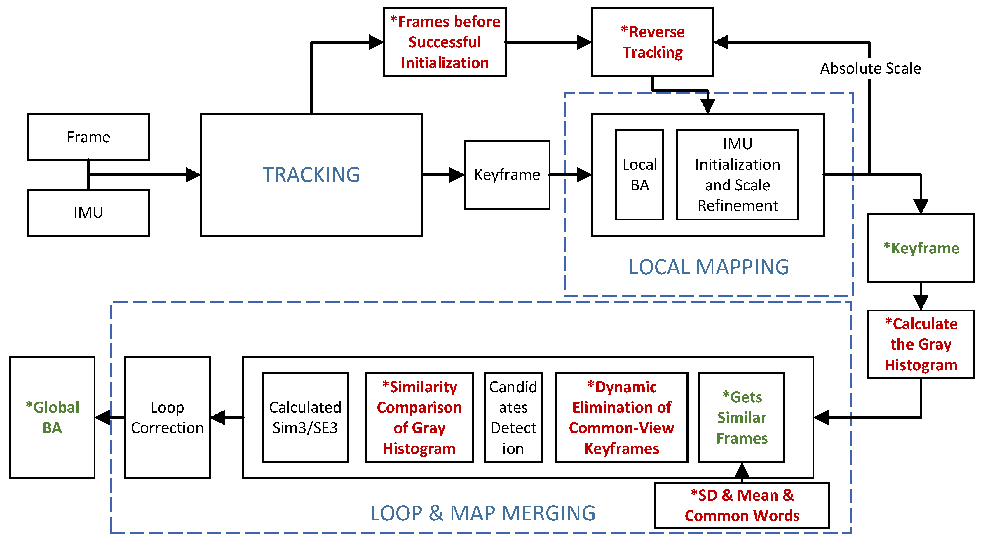
2.1. Overview of Real-Time Map Restoration Algorithms

This paper proposes a real-time map restoration algorithm based on ORB-SLAM3. The framework of the system proposed in this paper is shown in Figure 1. In the monocular inertial mode, each image frame will extract ORB feature points and calculate descriptors in the tracking thread. We insert frames that have extracted feature points into a custom stack for reuse. This stack stores all image frames up to the successful initialization of the current active map. In the local mapping thread, when the IMU initialization is successful and the second bundle adjustment (BA) optimization [28] is completed, the frame in the stack is quickly tracked, that is, from the first keyframe of the map to the earlier frame quickly matching and tracking one by one. Moreover, the process is parallel to the tracking thread. The detailed process is demonstrated in Section 2.2. In addition, when the keyframe is inserted from the local mapping thread into the loop closing thread, the grayscale image of the keyframe is adaptively clipped and the grayscale histogram is calculated. After normalization of the grayscale histogram, the standard deviation and mean value are calculated (details refer to Section 2.3). This facilitates the dynamic elimination of common-view frames, detection of candidate frames in loop closing threads, and similarity comparison of grayscale histograms.

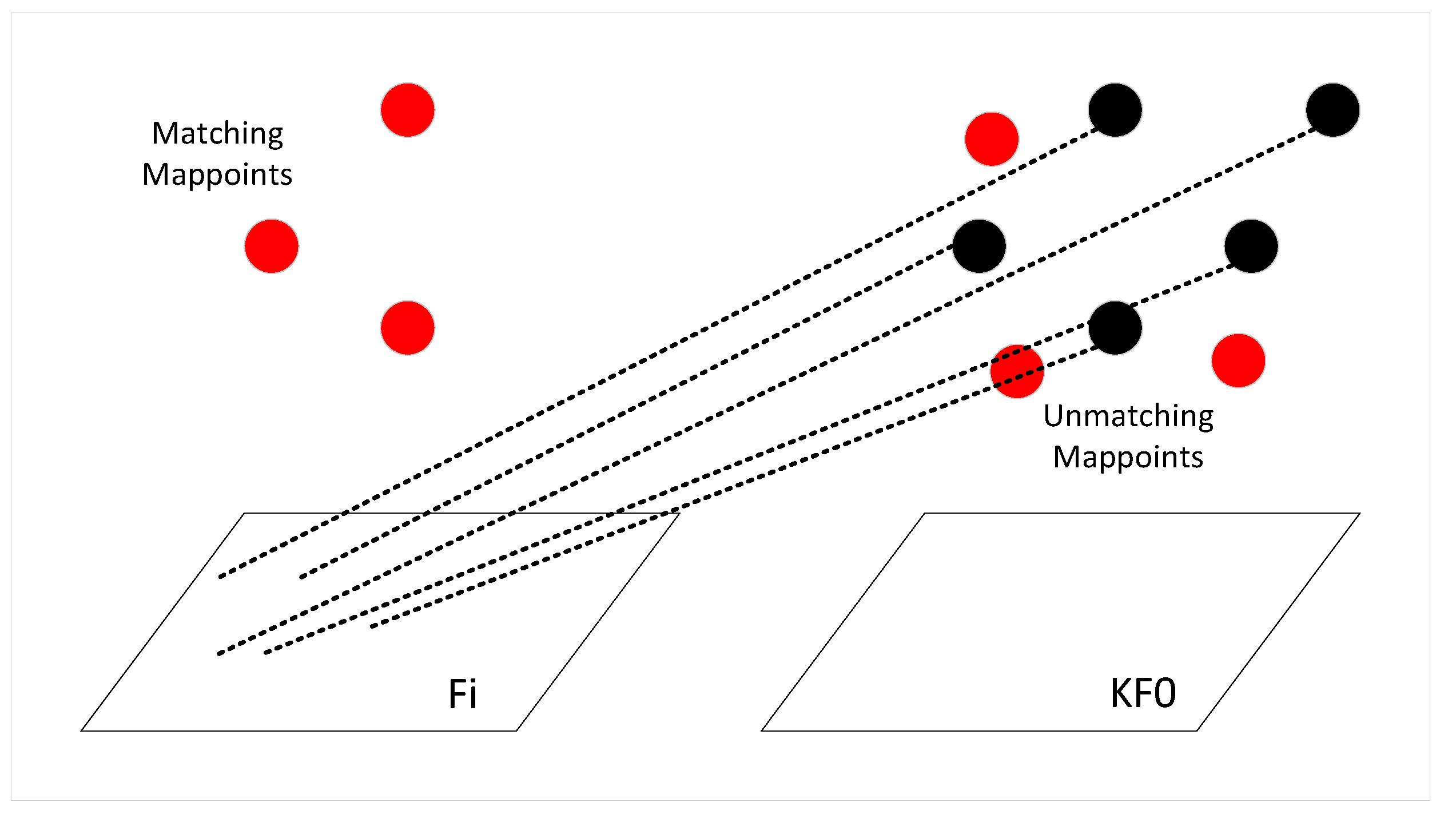
2.2. Map Restoration Based on Reverse Tracking

In the reverse tracking, we first take out a frame F i in the stack and precise positioning tracking. We quickly match F i with the first keyframe K F 0 in the current active map using a bag-of-words. In the matching process, only the feature points belonging to the same node are matched, and the number of successful matching points n is obtained. If the number meets the requirements, MLPNP is used to estimate the pose of F i . MLPNP not only decouples the relationship with the camera model, but also has the advantages of fast speed and high accuracy. Then, the chi-square test is used to eliminate the outliers, and the reprojection error is calculated according to Equation (1),
e = u u ¯ ,
where u is the pose of the feature point of F i on the pixel plane, u ¯ is the pose of the map point of K F 0 projected to the F i pixel plane. Affected by many independent factors, the reprojection error is random. According to the central limit theorem, the reprojection error obeys the Gaussian distribution,
e N 0 , C ,
where C is the covariance,
C = ( s n × p ) 2 1 0 0 1 ,
where s is the scaling factor of the image pyramid, p is the standard deviation of the 0th layer. The error term in Equation (1) is weighted by covariance to obtain an error scalar r,
r = e T C 1 e ,
which, according to the monocular projection, is 2 degrees of freedom, and the threshold of chi-square statistics is 5.99 at 0.05 significant level. We believe that the point greater than this threshold is the outlier, and the point less than this threshold is the interior point. When the number of interior points m is sufficient, we update the pose T c w in the world coordinate system of the current frame,
T c w = R c w t c w 0 T 1 ,
where R c w and t c w are the rotation and translation matrices from the world coordinate system to the current camera coordinate system, respectively.If the number of interior point m obtained in the previous step is small, as shown in Figure 2, the unmatched map points between frame K F 0 and F i are re-projected to the camera coordinate system of F i , and the new point pairs are obtained by using a more stringent threshold and smaller window matching. Finally, the pose optimization is carried out again.
After tracking F i and getting the pose, the fast reference frame tracking begins. After inserting F i into the keyframe queue, the mappoints are inserted into the point cloud map, and we update this frame as a reference keyframe for the image frame in the stack. The next frame F i 1 of pop stack is quickly matched with its reference keyframe through the bag-of-words, and then the mappoints of the reference keyframe are projected to F i 1 and the pose estimation is carried out according to MLPNP, so as to obtain the pose transformation of the frame in the world coordinate system. The pose transformation T c r of this frame relative to the reference frame is calculated according to Equation (6) and saved to the map file for the generation of map trajectory.
T c r = T c w × T w r T w r = T r w 1 T r w = R r w t r w 0 T 1
If the number of successful matching points of F i 1 is small, the steps similar to the completed precise positioning tracking between F i and K F 0 are performed. However, in addition to its reference keyframe, the keyframe quickly matched with F i 1 also contains a keyframe with high similarity found in the keyframe database. If the calculation condition of pose still does not meet the requirements, the pose of F i 1 is directly set as the pose of the previous image frame according to the principle that the pose between two adjacent image frames does not change dramatically. Follow this until the last image frame F 0 in the stack is tracked. After tracking, a complete map trajectory can be obtained, which contains more frame poses, and more mappoints in point cloud map. The generation of the trajectory does not care about the effect of initialization. Due to the use of all the information of the input sequence, there can also be a good pose within the range of the original unsuccessful initialization, so that the accuracy of the algorithm to estimate the trajectory will also be improved.
The tracking process simplifies the process of using a bag-of-words to search for matching, and adjusts the number of iterations in optimizing pose, which can make this process become extremely lightweight and ensure accuracy. Considering that the pose transformation between image frames is not regular in the initialization process, a constant speed is not used to estimate the pose of the next frame in this tracking process.

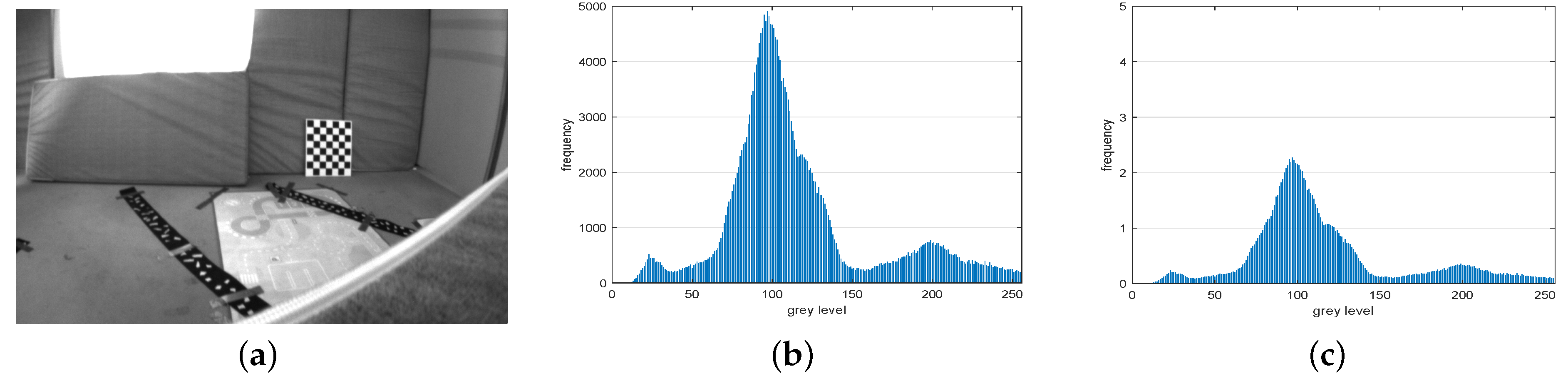
2.3. Loop Closure Detection Acceleration Based on Grayscale Histogram

The grayscale histogram of image frame has a small computational cost, but it can well reflect the pixel distribution characteristics of an image. In addition, the grayscale histogram has the advantages of translation, rotation and scaling invariance, which is very suitable for frame measurement in the SLAM system. In this paper, we use the grayscale histogram to accelerate the loop closure detection of each frame, so that the real-time performance of the map restoration algorithm is improved.
In the ORB-SLAM3 system, the local mapping thread will continuously insert keyframes into the keyframe queue of the loop closing thread, and then find out the similar keyframes in the database for the similarity judgment. If the similarity is high, this keyframe will be used as a candidate keyframe. When inserting a keyframe into the keyframe queue of the loop closing detection thread, we calculate the grayscale histogram of the keyframe. In the working process of the SLAM system, there is almost no case that the two frames are exactly the same. Therefore, the grayscale image I g r a y of the keyframe is adaptively clipped so that the grayscale histogram of the image can retain the main information of the image, and at the same time, the uncertainty caused by the perspective difference is reduced,
I g r a y = R e c t ( I g r a y , θ 1 , λ 1 , θ 2 , λ 2 ) ,
where R e c t denotes that the grayscale image I g r a y is cut from coordinates ( θ 1 , λ 1 ) to coordinates ( θ 2 , λ 2 ); θ represents the abscissa of the image coordinate system, λ represents the ordinate. Then, the grayscale histogram of the cut I g r a y is calculated to obtain H i s t . A total of 256 grayscale levels are taken from 0 to 255, and the number of pixels corresponding to each grayscale level is calculated, which can represent the frequency of the grayscale level,
H ( P ) = [ h ( x 0 ) , h ( x 1 ) , , h ( x 255 ) ] h ( x i ) = S ( x i ) j S ( x j ) ,
where S ( x i ) is the number of pixels in a grayscale level, j S ( x j ) is the total number of pixels. After calculating the grayscale histogram, in order to maintain the relative relationship between the two sets of data and make the data more comparable, the range of H i s t is normalized by Equation (9),
x o u t = β α δ γ ( x i n γ ) + α ,
where x i n and x o u t are the original values and the normalized values of each grayscale level, respectively. The range of values is mapped from ( γ , δ ) to ( α , β ). For example, Figure 3 shows the process of normalizing histogram (b) of the grayscale image (a) to obtain (c).
Then, the normalized grayscale histogram is used to calculate the mean and standard deviation according to Equation (10) as a rough image feature measure.
μ = 1 M × N i = 1 M j = 1 N P ( i , j ) S D = 1 M × N i = 1 M j = 1 N ( P ( i , j ) μ ) 2
where M × N is the size of the histogram, P ( i , j ) represents the value of line i and column j of the histogram.
After obtaining the histogram information of the keyframe, the keyframe is inserted into the loop closure detection queue, and ( μ , S D ) is used as the coordinate index to add the keyframe to the container that is connected by a mean and standard deviation. This operation makes the keyframes with a similar mean and standard deviation always stored in a certain interval of the container. Filter candidate keyframes first when loop closure detection. According to the container characteristics of the mean-SD structure, the keyframe group similar to the mean and standard deviation of the current keyframe K F i is taken out, and then all keyframes with common words with K F i are taken out from the keyframe group through the bag-of-words model and inverted index. This process can help us roughly and quickly exclude some impossible options, saving time for the SLAM system.
The obtained keyframe group is further eliminated according to the common view relationship. If the number of common view keyframes in K F i is m, the m frames connected to K F i will be directly eliminated, which is not used to calculate similar scores. Moreover, if the result of insufficient similarity between this keyframe and K F i is obtained by judging the similarity score; a one-way mark that is not used for detection will be added to this keyframe to illustrate that there is no similarity between this keyframe and K F i . According to this mark, when traversing the common words of other K F i and its similar keyframes, those with this mark will skip directly. This also saves a lot of computer resources, with less computational cost to save subsequent invalid duplicate calculations.
Then, a set of keyframes K M with a high similarity score is obtained by the bag-of-words matching and calculating the similarity score. According to the characteristics of bag-of-words matching, K M has high similarity with K F i in multiple parts, but in many textured similar environments, the overall similarity between K M and K F i is still not guaranteed. Thus, before K M is calculated by Sim3, we calculate the correlation between the grayscale histogram of K M and K F i to compare the overall grayscale distribution. Suppose the grayscale histogram of H 1 and H 2 , and the correlation between H 1 and H 2 is d ( H 1 , H 2 ) , then
d ( H 1 , H 2 ) = I ( H 1 ( I ) H ¯ 1 ) ( H 2 ( I ) H ¯ 2 ) I ( H 1 ( I ) H ¯ 1 ) 2 I ( H 2 ( I ) H ¯ 2 ) 2 ,
where,
H ¯ k = 1 N j H k ( j )
If d ( H 1 , H 2 ) is closer to 1, it is considered that the correlation between H 1 and H 2 is higher. Although the high correlation between two grayscale images cannot be obtained from the high correlation between grayscale histograms, it can be concluded that there is no similarity between two grayscale images if the correlation between grayscale histograms is insufficient. Combined with the previous bag-of-words model screening, if d ( H 1 , H 2 ) is greater than a certain threshold (0.8 in this paper), it can be determined that the similarity between the two frames is high enough. On the contrary, if d ( H 1 , H 2 ) is less than the threshold, skip the current keyframe and judge the next keyframe. In the subsequent test, the situation that the candidate frame is abandoned due to poor frame quality will not occur.
If the candidate keyframes K M that meets all the above conditions is obtained, a local window W m is defined. The window contains K M and several keyframes with the highest degree of common view. The set of all mappoints in W m is X m . Mappoints of X m and K F i are matched by a bag-of-words. Then, the Sim3 solver is constructed, and the initial relative pose T a m of W m and K F i is solved by RANSAC. Through T a m , the mappoints in the window and the mappoints in K F i are projected bidirectionally similar to Figure 2, so as to obtain more matching points. According to Equation (1), a more accurate relative pose is obtained by nonlinear optimization by minimizing the reprojection error. If the number of interior points is greater than a certain threshold, a more stringent search radius and Hamming distance are used to match again. Otherwise this process is repeated to obtain a relative pose with the highest accuracy.
After the T a m is calculated, in order to prevent the loop closure failure, it is necessary to check the keyframes like a collection card. This process follows the geometric consistency check in [17] and the loopback continuity check in [5]. Firstly, the geometric consistency check is performed. This process does not depend on time continuity, and K M is verified by the degree of common-view between its keyframes and K F i . If the common-view keyframes of K M have enough matching points with K F i , it is recorded as a successful verification. Traverse these common-view keyframes, and if at least three of them pass the check, exit the check process. Otherwise, the loopback continuity check is performed. The loop closure detection results are verified by projecting X m to the newly generated keyframes for matching, and the pose of Sim3 is optimized. If the number of matching points meets the requirements, it is recorded as a validation success. If the total number of verification successes (geometric consistency check and loopback continuity check) reaches three times, the detection process will be directly exited, and the final roll angle, pitch angle and yaw angle will be judged. In ORB-SLAM3, the roll angle and pitch angle are required to be less than 0.46°, and the yaw angle is less than 20°, otherwise the loopback result is considered bad. If the above conditions are met, loopback correction will be performed.

3. Simulation Results and Performance Analysis

In order to verify the effectiveness of the proposed algorithm, this paper uses the visual-inertial dataset Euroc [29] collected by a micro aerial vehicle (MAV) for simulation. Euroc contains 11 stereo video sequences, and the dataset environment is divided into indoor rooms and factories. Firstly, according to the different initialization effects caused by different motion characteristics of each sequence, the dataset is divided into two categories, where MH01∼MH05 is the sequence with difficulty in initialization, and V101∼V203 is the sequence with easy initialization. Since V203 contains motion blur and loop closure, we use it as a sequence to verify time efficiency. The simulation platform is an Intel (R) Core (TM) i7-7700HQ CPU @ 2.80GHz, 24G RAM computer.

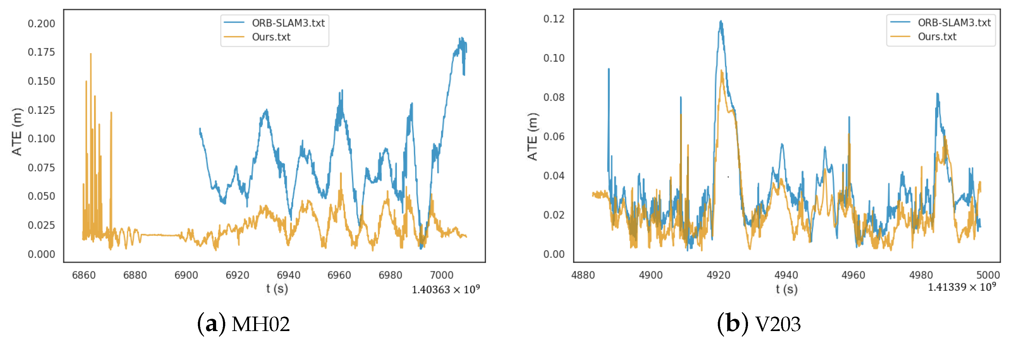
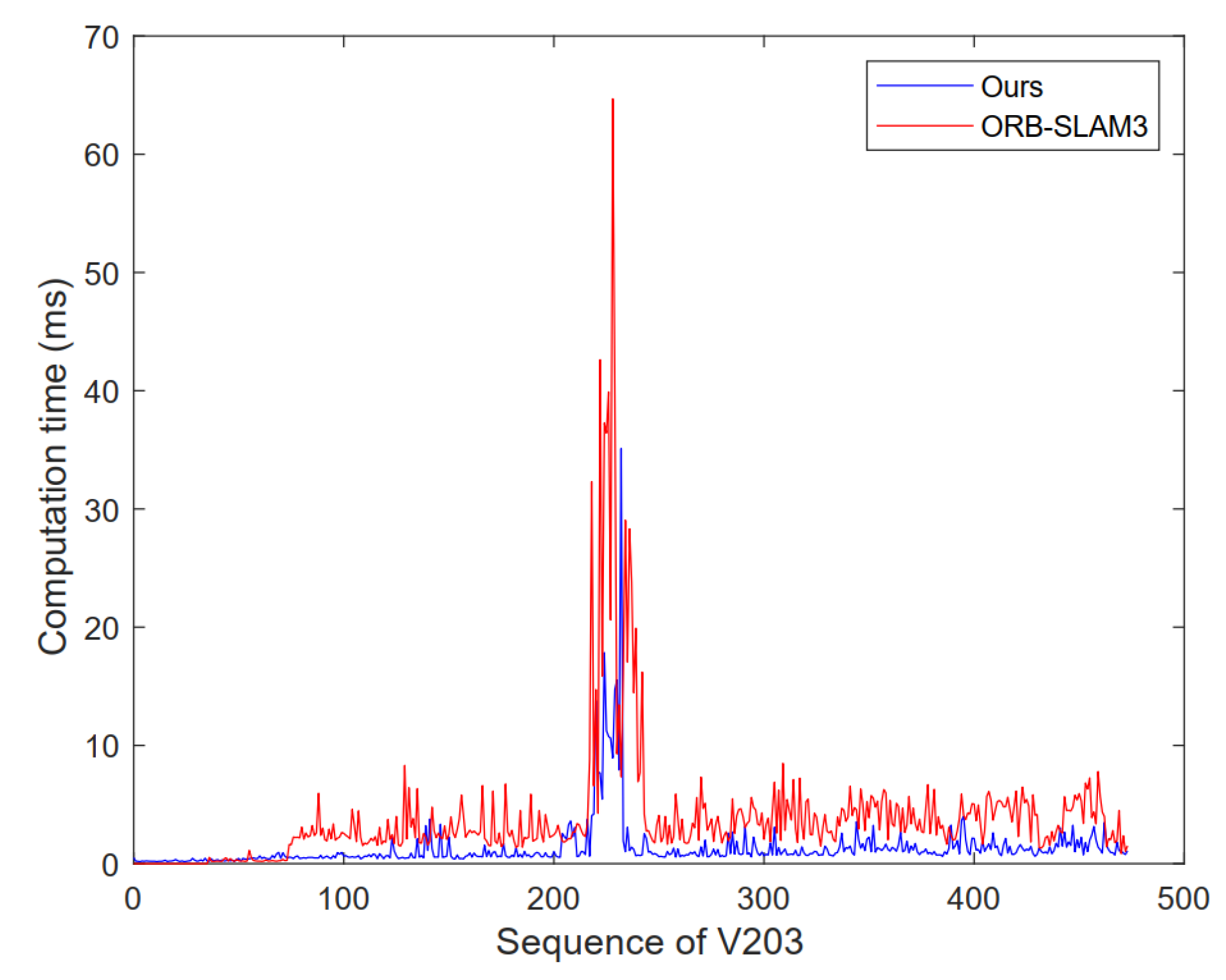
3.1. Quantitative Analysis

This paper first provides the number of the pose and trajectory length of the map generated after running on a Euroc dataset before and after the improvement of the ORB-SLAM3 algorithm, and according to Equations (13) and (14), the effect of the number of Pose and trajectory length recovery by the algorithm in this paper compared with ORB-SLAM3.
σ P o s e = ( β α 1 ) × 100 %
σ T r a j = ( γ μ 1 ) × 100 %
where σ P o s e is the effect of the Pose recovery, σ T r a j is the effect of trajectory recovery, α and β , μ and γ are the number of the Pose and the total length of map trajectory before and after the algorithm improvement. In order to eliminate interference as much as possible and ensure the rationality of the experimental data, the experimental data are the result of taking the median value after running the Euroc dataset ten times, such as Table 1.
A more complete map can be generated when there are more Poses or fewer discarded frames. The length difference of map trajectory can also intuitively reflect the effect of mapping and the distance consumed by the algorithm initialization. Due to the recovery tracking and mapping of discarded frames during initialization, this algorithm must have a longer map trajectory than ORB-SLAM3. However, in the initialization, due to different motion modes of different datasets, the effect of map restoration in this paper is different.
The initialization of the visual-inertial SLAM system needs to meet the following conditions at the same time: the perspective changes slowly, the tracking thread works normally, and the IMU excitation is stable and sufficient.
For example, in the MH02 sequence, the initialization of the system can be divided into three stages, namely the vertical reciprocating motion, horizontal reciprocating motion, and horizontal circular motion. Visual-inertial SLAM systems face different challenges at each stage. In the first stage, the local map tracking fails due to the rapid change of perspective, so that the SLAM system cannot create the map. In the second stage, the map cannot be created and the IMU cannot be initialized because the tracking thread is still not working properly. In the third stage, the three conditions for initialization are satisfied, thus completing the computation of the IMU residual, bias and BA optimization of the first part. However, the MAV then landed on the take-off platform, and the lack of excitation of the IMU caused the initialization to fail again. In these three stages, the current ORB-SLAM3 algorithm cannot complete the initialization and loses a lot of initialization information. The initialization cannot be completed until the next time the MAV leaves the platform, however, the map created does not include the map information of the first three stages.
After the recovery tracking of the algorithm in this paper, the Pose recovery of 41.36% can be achieved on the MH02 sequence. Since some frames are stationary, namely, the pose difference is small, the actual trajectory recovery is 14.91%, about 9.771 m. It can be observed from Table 1 that the initialization effect of ORB-SLAM3 is poor in the factory environment; thus, the effect is better after the algorithm is improved in this paper. In the sequence of room environment in V101∼V203, ORB-SLAM3 can be initialized quickly, so the effect after recovery and tracking has little improvement, and the recovered trajectory length is only about half a meter away.
Secondly, for example, Table 2, this paper also counts the root mean square error (RMSE) and standard deviation of the ATE to reflect the improvement of robustness and stability of the proposed algorithm compared with the ORB-SLAM3. RMSE can well reflect the global consistency, such as Equations (15) and (16),
R M S E ( F 1 : n ) : = ( 1 n i = 1 n t r a n s ( F i ) 2 ) 1 2 ,
F i : = Q i 1 S P i ,
where t r a n s ( F i ) represents the translation part of the ATE, Q i S E ( 3 ) is the ground truth, P i S E ( 3 ) is the estimated pose, and S S E ( 3 ) is the transformation matrix from P i to Q i . The improvement of the time efficiency of the proposed algorithm is analyzed by calculating the time spent by the SLAM system in the loop closure detection and the mean tracking time of each frame. Table 3 reflects the improvement of each sequence in the Euroc dataset.
After comparing and analyzing the proposed algorithm with ORB-SLAM3 using Euroc dataset, it can be observed that under the same conditions (compared with the complete trajectory of the ground truth), RMSE, standard deviation, mean tracking time and loop closure detection time of the proposed algorithm are reduced. The RMSE of 11 sequences decreased by 47.51% on average, and the accuracy was improved significantly. Among them, the RMSE on MH01∼MH05 sequence is much lower, which is because the number of Pose recovered by the algorithm in this paper on these sequences is up to several hundred, and the final reconstructed map trajectory is long. More information can be provided to the map after trajectory recovery, and keyframes created during tracking can also be involved in global optimization to further improve accuracy. At the same time, because the time efficiency of the SLAM system is improved, there are more sufficient computer resources to complete BA optimization and more stable tracking image frames. The RMSE reduction in V101∼V203 is less than in the factory environment. This is because in the sequence of these room scenes, the image frame and IMU data obtained by SLAM system are good and can complete rapid initialization, so the accuracy improvement effect of this algorithm on these sequences is limited. Secondly, the average decline of standard deviation on Euroc dataset is 52.18%, which indicates that the proposed algorithm is more stable than the original algorithm and can run SLAM system consistently.
In addition, this algorithm can also significantly improve the time efficiency. In the Euroc dataset, tracking the time efficiency increased by 12.91% on average, and the detection time efficiency increased by 55.96% on average. Similarly, the time efficiency is significantly improved in the sequences with difficulty in initialization, which is due to the computational lightweight of the map restoration algorithm in this paper. Of course, the improvement is not high in the easy initialization sequence. It is worth noting that V103, V202 and V203 sequences are easy to initialize, but there are loop closures in their sequences. After the loop closure, the number of common-view keyframes will increase significantly, so that more frames can be eliminated, and the detection time and tracking time can be significantly reduced.
Therefore, compared with ORB-SLAM3, the proposed algorithm can first generate a complete map, and then significantly improve the accuracy and time efficiency of the difficult initialization sequence. According to the characteristics of the algorithm, in the environment that initialization is easier to fail and the number of loop closure is more, or when the system runs longer, the accuracy and time efficiency of the system are improved more obviously.

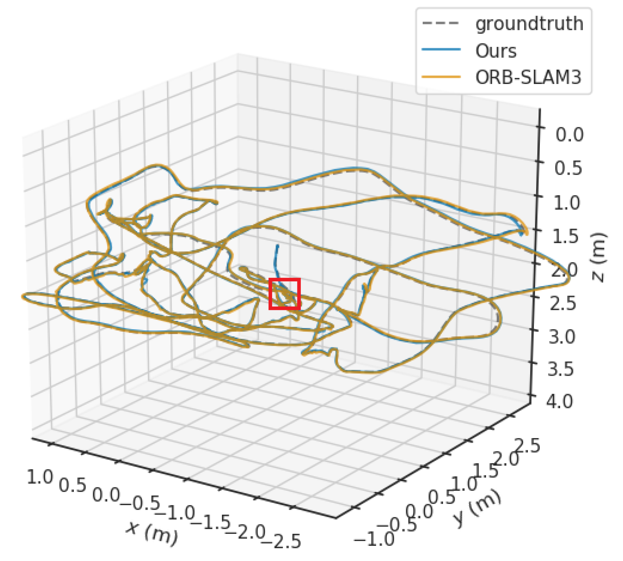
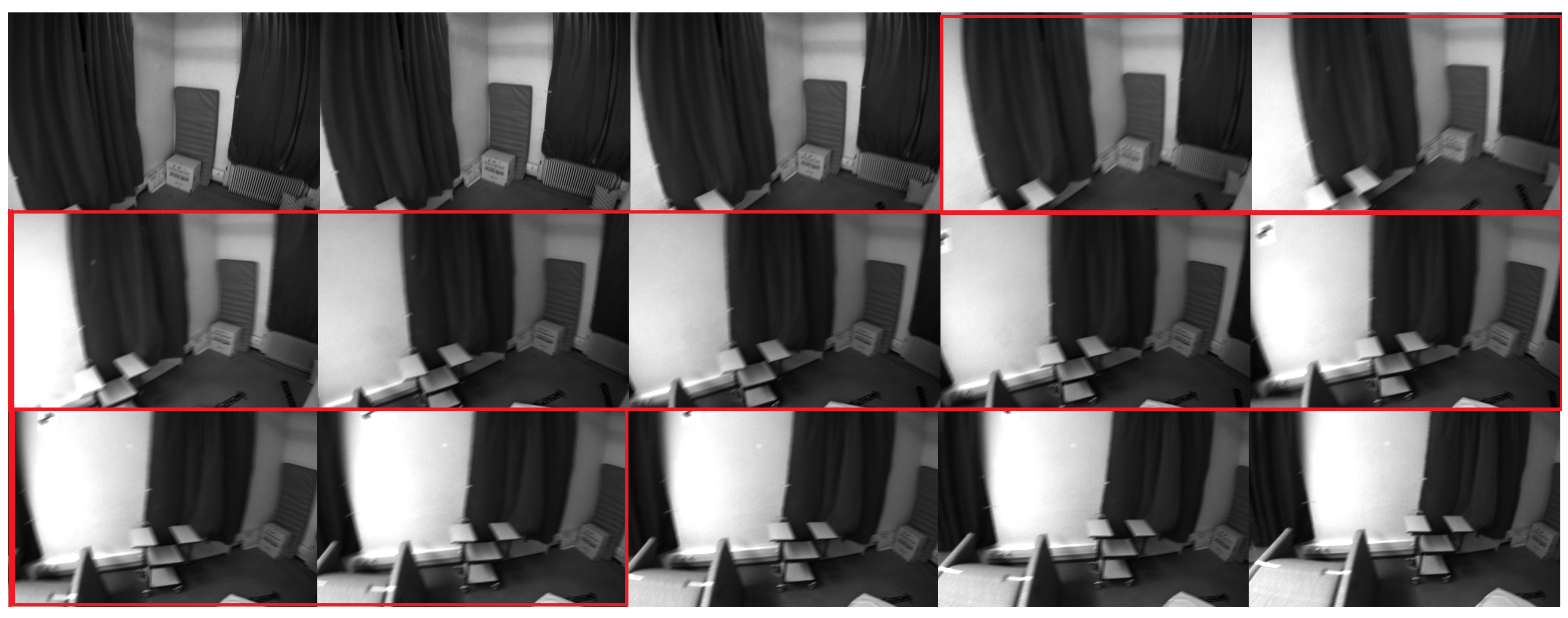
3.2. Qualitative Analysis

In order to evaluate the performance impact of the proposed algorithm on the SLAM system more intuitively, two representative sequences (MH02 and V203) are selected and qualitatively analyzed. This is where the MH02 is the sequence with difficulty in initialization, and V203 is the sequence with easy initialization. First, the differences between the estimated trajectories before and after the algorithm improvement and the groundtruth trajectories are compared. Then, the difference of RMSE of ATE between the two algorithms is compared.
As shown in Figure 4 and Figure 5, the trajectories on the MH02 sequence and the V203 sequence are compared, respectively. The blue line is the trajectory generated by the algorithm in this paper, the brown line is the trajectory generated by ORB-SLAM3, and the gray dotted line represents the ground truth trajectory. The red rectangle in the figure marks the position where ORB-SLAM3 initialization is completed.
It is obvious that ORB-SLAM3 loses a large part of the initial map information when faced with challenging sequences (MH02). In this case, the map recovered by the proposed algorithm has higher value. On the other hand, in the easily initialized sequence (V203), the maps we can recover are limited because ORB-SLAM3 is able to complete the initialization at an earlier position.
As shown in Figure 6, the ATE of the proposed algorithm (yellow) is smaller than that of ORB-SLAM3 (blue) in both difficult and easy initialization sequences, and is more obvious in difficult initialization sequences. Due to the slow initialization of ORB-SLAM3 in the MH02 sequence, there is no data at the beginning. In addition, some outliers will be generated in our restored map. This is because there are many static scenes at the beginning of the sequence, and it is unstable to process this information through vision. However, the effectiveness of the map will not be affected by these few outliers. We further analyze the ATE of the two, as shown in Figure 7. The blue part of the box plot is ORB-SLAM3, and the brown part is the algorithm in this paper. It can be clearly observed that the data obtained by the proposed algorithm are more concentrated, and they are all concentrated in areas with small ATE. The above is the qualitative analysis of the proposed algorithm. Next, V203 is taken as an example to analyze the improvement of the time efficiency of the loop closure detection part by the proposed algorithm.
V203 is a fast moving sequence with motion blur. In this sequence, a large number of repeated scenes begin to appear in the middle and late stages. The SLAM system should complete loop closure detection and loop correction during this period. However, not all frames can be used as the reference frames of the loop, because most frames are blurred or the rpy direction angle changes too much. Although these frames can extract feature points and match them, they will eventually be abandoned. Therefore, there are many times of invalid calculations in V203 due to the above reasons, in which each calculation takes tens of milliseconds, which seriously wastes computer resources. However, the grayscale histogram is very sensitive to the changes of pitch angle, roll angle and yaw angle. If one of the changes is too large, the grayscale distribution of image frames will change greatly. According to this feature, the proposed algorithm eliminates these image frames which may cause invalid calculation in advance, thus improving the quality of input frames.
Figure 8 shows the comparison of the time-consumed for loop detection in each frame of the V203 sequence, where blue is the proposed algorithm and red is ORB-SLAM3. It is obvious that the time-consuming of the proposed algorithm is generally significantly lower than that of ORB-SLAM3. When a large number of similar frames appear in the medium term, many calculations over 10 ms are performed in ORB-SLAM3. However, the proposed algorithm completes the loop correction process only after two such calculations.
It is worth noting that on the same sequence, the loop completion time of the proposed algorithm is slightly earlier than that of ORB-SLAM3. This is because when ORB-SLAM3 calculates and optimizes the pose, it takes too much time, resulting in missing the most suitable loop candidate frame, and only finding the appropriate loop candidate frame after the calculation is completed.
Around 230 of the sequence, the loop closure detection process is mainly concentrated here. For example, loop closures can be detected by the bag-of-words model in both Figure 9a,b, but only the keyframe pair in Figure 9a can finally pass the loop closure check. In Figure 9b, the computer reappears at the same angle, so some descriptors are successfully matched. By matching using the bag-of-words model, we think that the camera came to the same location. However, in this keyframe pair, the computer is at different distances in the image, and the roll angle of the camera changes significantly. In the loop closure check, because the scale of the feature points has a large difference or the angle of the rpy direction changes too much, we think that the loop closure at this time has a great risk, and thus reject the loop closure. However, this situation can be effectively avoided by improved methods. For example, the grayscale histogram similarity of the keyframe pair in Figure 9a is 0.9782, and in Figure 9b is 0.6659. Therefore, the loop closure in Figure 9b will be eliminated early.
More importantly, when we combine Figure 6b, Figure 8 and Figure 9, we can understand why there are some larger ATEs at certain time spots. We found that in the V203 sequence, its ATE was larger during the period when loop closures were easily identified. This is because different threads need to coordinate the allocation of computer resources when the SLAM system processes tasks. Moreover, when ORB-SLAM3’s loop closing thread requests more time to process the loopback, the work of tracking the thread becomes more challenging. As a result, the accuracy of the Poses we obtain will decrease. Of course, not all larger ATEs are only affected by time efficiency. As shown in Figure 9b and Figure 10, motion blur and large scale changes will affect our accuracy. In general, both motion blur and scale differences will affect the quality of the feature points extracted by the SLAM system. When we use these feature points to track and estimate pose, there will be fluctuations in accuracy.

4. Conclusions

This paper proposes a real-time map restoration algorithm based on ORB-SLAM3. This method reversely tracks all frames before successful initialization, and accelerates the loop closure detection. We can generate a complete map in real time regardless of the initialization effect of the system. After comparing the RMSE of ATE, the accuracy was increased by 47.51% on average. Compared with standard deviation, the stability is increased by 52.18% on average. After comparing the time consumption, the time efficiency in the loop closure detection stage increases by 55.96% on average, and the average tracking time of the system decreases by 13% on average. Experiments show that the proposed algorithm can achieve map restoration while ensuring real-time performance. The complete map generated by this algorithm is significant for off-line robot tracking.
The map restoration method proposed in this paper is mainly for the scenes with difficult initialization, and the effect is not obvious in simple scenes. In addition, the proposed algorithm is based on the assumption of low dynamic environment and does not eliminate dynamic objects, so the accuracy in an high dynamic environment will decrease. In the future, dynamic detection function should be added so that robots can adapt to more complex environments.

Author Contributions

All named authors initially contributed a significant part to the paper. Conceptualization, Q.L.; methodology, Q.L.; software, Q.L.; validation, Q.L.; formal analysis, Q.L. and J.L.; investigation, Q.L. and J.L.; data curation, Q.L.; writing—original draft preparation, Q.L.; writing—review and editing, W.H., Q.L., J.L. and K.Z.; visualization, Q.L.; supervision, W.H., Q.L., J.L. and L.S.; project administration, W.H., Q.L., J.L. and H.Q. All authors have read and agreed to the published version of the manuscript.

Funding

This research received no external funding.

Institutional Review Board Statement

Not applicable.

Informed Consent Statement

Not applicable.

Data Availability Statement

Publicly available datasets were analyzed in this study. This data can be found here: https://projects.asl.ethz.ch/datasets/doku.php?id=kmavvisualinertialdatasets (accessed on 3 May 2022).

Conflicts of Interest

The authors declare no conflict of interest.

Abbreviations

The following abbreviations are used in this manuscript:
SLAMSimultaneous Localization and Mapping
IMUInertial Measurement Unit
MSCKFMulti-State Constraint Kalman Filter
MLPNPMaximum Likelihood Solution to The Perspective-N-Point
VIOVisual Inertial Odometry
OPENVINSOpen Visual-Inertial SLAM
VINSVisual-Inertial SLAM
EKFExtended Kalman filter
ARUCOAugmented Reality University of Cordoba
LSD-SLAMLarge-Scale Direct SLAM
SVOSemidirect Visual Odometry
ORBORiented Brief
LKLucas–Kanade
RGB-DRGB-Depth
CPUCentral Processing Unit
SSDSingle Shot Multibox Detector
OKVINSOpen Keyframe-Based Visual-Inertial SLAM
BRISKBinary Robust Invariant Scalable Keypoints
PGOPose Graph Optimizer
SFMStructure From Motion
RANSACRandom Sampling Consensus
Sim3Similar Transformation Using 3 Pairs of Points
MAVMicro Aerial Vehicle
BABundle Adjustment
ATEAbsolute Trajectory Error
RMSERoot Mean Square Error
SDStandard Deviation

References

  1. Mourikis, A.I.; Roumeliotis, S.I. A Multi-State Constraint Kalman Filter for Vision-aided Inertial Navigation. In Proceedings of the 2007 IEEE International Conference on Robotics and Automation, Rome, Italy, 10–14 April 2007; pp. 3565–3572. [Google Scholar] [CrossRef]
  2. Geneva, P.; Eckenhoff, K.; Lee, W.; Yang, Y.; Huang, G. OpenVINS: A Research Platform for Visual-Inertial Estimation. In Proceedings of the 2020 IEEE International Conference on Robotics and Automation (ICRA), Paris, France, 31 May–31 August 2020; pp. 4666–4672. [Google Scholar] [CrossRef]
  3. Engel, J.; Schops, T.; Cremers, D. LSD-SLAM: Large-Scale Direct monocular SLAM. In Proceedings of the 13th European Conference, Zurich, Switzerland, 6–12 September 2014; Volume 8690 LNCS, pp. 834–849. [Google Scholar]
  4. Forster, C.; Zhang, Z.; Gassner, M.; Werlberger, M.; Scaramuzza, D. SVO: Semidirect Visual Odometry for Monocular and Multicamera Systems. IEEE Trans. Robot. 2017, 33, 249–265. [Google Scholar] [CrossRef] [Green Version]
  5. Mur-Artal, R.; Tardós, J.D. ORB-SLAM2: An Open-Source SLAM System for Monocular, Stereo, and RGB-D Cameras. IEEE Trans. Robot. 2017, 33, 1255–1262. [Google Scholar] [CrossRef] [Green Version]
  6. Rublee, E.; Rabaud, V.; Konolige, K.; Bradski, G. ORB: An efficient alternative to SIFT or SURF. In Proceedings of the 2011 International Conference on Computer Vision, Barcelona, Spain, 6–13 November 2011; pp. 2564–2571. [Google Scholar] [CrossRef]
  7. Li, C.; Zhang, X.; Cao, T. SLAM with mapping based on photometric information and ORB features. J. East China Univ. Sci. Technol. 2021, 47, 331–339. [Google Scholar] [CrossRef]
  8. Yu, C.; Liu, Z.; Liu, X.J.; Xie, F.; Yang, Y.; Wei, Q.; Fei, Q. DS-SLAM: A Semantic Visual SLAM towards Dynamic Environments. In Proceedings of the 2018 IEEE/RSJ International Conference on Intelligent Robots and Systems (IROS), Madrid, Spain, 1–5 October 2018; pp. 1168–1174. [Google Scholar] [CrossRef] [Green Version]
  9. Badrinarayanan, V.; Kendall, A.; Cipolla, R. SegNet: A Deep Convolutional Encoder-Decoder Architecture for Image Segmentation. IEEE Trans. Pattern Anal. Mach. Intell. 2017, 39, 2481–2495. [Google Scholar] [CrossRef] [PubMed]
  10. Hornung, A.; Wurm, K.M.; Bennewitz, M.; Stachniss, C.; Burgard, W. OctoMap: An efficient probabilistic 3D mapping framework based on octrees. Auton. Robot. 2013, 34, 189–206. [Google Scholar] [CrossRef] [Green Version]
  11. Bescos, B.; Fácil, J.M.; Civera, J.; Neira, J. DynaSLAM: Tracking, Mapping, and Inpainting in Dynamic Scenes. IEEE Robot. Autom. Lett. 2018, 3, 4076–4083. [Google Scholar] [CrossRef] [Green Version]
  12. Zhong, F.; Wang, S.; Zhang, Z.; Chen, C.; Wang, Y. Detect-SLAM: Making Object Detection and SLAM Mutually Beneficial. In Proceedings of the 2018 IEEE Winter Conference on Applications of Computer Vision (WACV), Lake Tahoe, NV, USA, 12–15 March 2018; pp. 1001–1010. [Google Scholar] [CrossRef]
  13. Liu, W.; Anguelov, D.; Erhan, D.; Szegedy, C.; Reed, S.; Fu, C.Y.; Berg, A.C. SSD: Single shot multibox detector. In Proceedings of the 14th European Conference, Amsterdam, The Netherlands, 11–14 October 2016; Volume 9905 LNCS, pp. 21–37. [Google Scholar]
  14. Leutenegger, S.; Lynen, S.; Bosse, M.; Siegwart, R.; Furgale, P. Keyframe-based visual–inertial odometry using nonlinear optimization. Int. J. Robot. Res. 2015, 34, 314–334. [Google Scholar] [CrossRef] [Green Version]
  15. Qin, T.; Li, P.; Shen, S. VINS-Mono: A Robust and Versatile Monocular Visual-Inertial State Estimator. IEEE Trans. Robot. 2018, 34, 1004–1020. [Google Scholar] [CrossRef] [Green Version]
  16. Rosinol, A.; Abate, M.; Chang, Y.; Carlone, L. Kimera: An Open-Source Library for Real-Time Metric-Semantic Localization and Mapping. In Proceedings of the 2020 IEEE International Conference on Robotics and Automation (ICRA), Paris, France, 31 May–31 August 2020; pp. 1689–1696. [Google Scholar] [CrossRef]
  17. Martinez, C.C.; Elvira, R.; Gomez Rodriguez, J.J.; Montiel, J.M.; Tardos, J.D. ORB-SLAM3: An accurate open-source library for visual, visual-inertial and multi-map SLAM. IEEE Trans. Robot. 2021, 37, 1874–1890. [Google Scholar]
  18. Campos, C.; Montiel, J.M.; Tardós, J.D. Inertial-Only Optimization for Visual-Inertial Initialization. In Proceedings of the 2020 IEEE International Conference on Robotics and Automation (ICRA), Paris, France, 31 May–31 August 2020; pp. 51–57. [Google Scholar] [CrossRef]
  19. Elvira, R.; Tardós, J.D.; Montiel, J. ORBSLAM-Atlas: A robust and accurate multi-map system. In Proceedings of the 2019 IEEE/RSJ International Conference on Intelligent Robots and Systems (IROS), lMacau, China, 3–8 November 2019; pp. 6253–6259. [Google Scholar] [CrossRef] [Green Version]
  20. Wu, R.; Pike, M.; Lee, B.G. DT-SLAM: Dynamic Thresholding Based Corner Point Extraction in SLAM System. IEEE Access 2021, 9, 91723–91729. [Google Scholar] [CrossRef]
  21. Li, X.; Wu, H.; Chen, Z. Dynamic Objects Recognizing and Masking for RGB-D SLAM. In Proceedings of the 2021 4th International Conference on Intelligent Autonomous Systems (ICoIAS), Wuhan, China, 14–16 May 2021; pp. 169–174. [Google Scholar] [CrossRef]
  22. Hu, Z.; Zhao, J.; Luo, Y.; Ou, J. Semantic SLAM Based on Improved DeepLabv3+ in Dynamic Scenarios. IEEE Access 2022, 10, 21160–21168. [Google Scholar] [CrossRef]
  23. Liu, Y.; Miura, J. RDS-SLAM: Real-Time Dynamic SLAM Using Semantic Segmentation Methods. IEEE Access 2021, 9, 23772–23785. [Google Scholar] [CrossRef]
  24. Zhang, A.S.; Liu, B.S.; Zhang, C.J.; Wang, D.Z.; Wang, E.X. Fast initialization for feature-based monocular slam. In Proceedings of the 2017 IEEE International Conference on Image Processing (ICIP), Beijing, China, 17–20 September 2017; pp. 2119–2123. [Google Scholar] [CrossRef]
  25. Cheng, J.; Zhang, L.; Chen, Q.; Zhou, K.; Long, R. A Fast and Accurate Binocular Visual-Inertial SLAM Approach for Micro Unmanned System. In Proceedings of the 2021 IEEE 4th International Conference on Electronics Technology (ICET), Chengdu, China, 7–10 May 2021; pp. 971–976. [Google Scholar] [CrossRef]
  26. Yang, Y.; Xiong, J.; She, X.; Liu, C.; Yang, C.; Li, J. Passive Initialization Method Based on Motion Characteristics for Monocular SLAM. Complexity 2019, 2019, 8176489. [Google Scholar] [CrossRef] [Green Version]
  27. Urban, S.; Leitloff, J.; Hinz, S. MLPNP—A real-time maximum likelihood solution to the perspective-n-point problem. In Proceedings of the ISPRS Annals of the Photogrammetry, Remote Sensing and Spatial Information Sciences, 2016 XXIII ISPRS Congress, Prague, Czech Republic, 12–19 July 2016; Volume III-3, pp. 131–138. [Google Scholar]
  28. Triggs, B.; McLauchlan, P.F.; Hartley, R.I.; Fitzgibbon, A.W. Bundle adjustment a modern synthesis. In Proceedings of the International Workshop on Vision Algorithms, Corfu, Greece, 21–22 September 1999; Springer: Berlin/Heidelberg, Germany, 2000; Volume 1883, pp. 298–372. [Google Scholar]
  29. Burri, M.; Nikolic, J.; Gohl, P.; Schneider, T.; Rehder, J.; Omari, S.; Achtelik, M.W.; Siegwart, R. The EuRoC micro aerial vehicle datasets. Int. J. Robot. Res. 2016, 35, 1157–1163. [Google Scholar] [CrossRef]
Figure 1. System overview. Our system pipeline is an extension of ORB-SLAM3 [17]. Compared with ORB-SLAM3, the main improvements of our system have been marked with “*” in the flowchart. The red part indicates new additions, and the green indicates improvements.
Applsci 12 07780 g001
Figure 2. Reprojection of mappoints. The red points is the mappoints that has been matched between the two frames, and the black points is the unmatched mappoints. This process is used to generate new matching relations.
Applsci 12 07780 g002
Figure 3. Examples of normalization of grayscale histogram. (a) A room image in Euroc dataset. (b) The grayscale histogram of the image. (c) Normalized grayscale histogram.
Applsci 12 07780 g003
Figure 4. Trajectory comparison in the MH02 sequence.
Applsci 12 07780 g004
Figure 5. Trajectory comparison in the V203 sequence.
Applsci 12 07780 g005
Figure 6. Comparison of ATE (raw date). (a) and (b) are the ATE comparison between the proposed algorithm and ORB-SLAM3 in MH02 sequence and V203 sequence respectively. The yellow line represents the result of the proposed algorithm, and the blue line represents the result of ORB-SLAM3.
Applsci 12 07780 g006
Figure 7. Comparison of ATE (box plot). (a,b) are the comparison of ATE between the proposed algorithm and ORB-SLAM3 in MH02 sequence and V203 sequence, respectively, by box plot. The results of ORB-SLAM3 are shown in blue and ours are shown in brown.
Applsci 12 07780 g007
Figure 8. Computation time used to loop closure detection for each frame in V203.
Applsci 12 07780 g008
Figure 9. Pairs of keyframes detected by loop closures in V203 sequences and their grayscale histograms. (a) Good loopback situation. The loopback detection thread can usually complete the loopback here. (b) Bad loopback situation. The loopback detection thread is prone to loopback rejections here.
Applsci 12 07780 g009
Figure 10. Motion blur in V203 sequences. The image in the red rectangle is the blurred image.
Applsci 12 07780 g010
Table 1. Comparison of ORB-SLAM3 and proposed algorithm. It includes the comparison and improvement of the number of the Pose and the trajectory length (unit in meters). The Pose is estimated by the SLAM system according to the video sequence, and its number is the same as the number of the Pose in the trajectory file.
SequenceNumber of PoseGainsTrajectoryGains
ORBSLAM3OursORBSLAM3Ours
MH01354836803.72%78.82683.2535.62%
MH022207303741.36%65.51775.28814.91%
MH032282269818.23%128.725141.72210.11%
MH041605203226.60%91.038102.44912.53%
MH051789226226.44%95.522110.08015.24%
V101280028943.36%58.41358.8280.71%
V102159217057.11%75.47878.7274.30%
V103200021396.95%79.12779.9351.02%
V201218322754.21%37.36837.7210.94%
V202226923463.41%83.74484.1650.50%
V203181019176.44%87.07687.5700.57%
Table 2. Comparison of absolute trajectory error (ATE) and time efficiency. The mean time (unit in second) is the time consumed by tracking each frame, and the detection time (unit in millisecond) is the time consumed by each frame in the loop closure detection.
SequenceRMSEStandard DeviationMean TimeDetect Time
ORBSLAM3OursORBSLAM3OursORBSLAM3OursORBSLAM3Ours
MH010.0422740.0214420.0280040.0089020.034480.027022.001820.72322
MH020.0899790.0257430.0357640.0133150.035910.027681.461970.66376
MH030.1440680.0352200.0950120.0177780.032320.028142.312371.09805
MH040.1400390.1343850.0680270.0608910.031180.024702.587961.55749
MH050.4920240.0575850.3000620.0267580.030730.025902.564321.40208
V1010.0580890.0355300.0277760.0120110.030590.029862.248150.95563
V1020.0742440.0179520.0631030.0118320.028310.026152.185410.85070
V1030.0199570.0189030.0087850.0088860.028240.024932.362210.85074
V2010.0483770.0284860.0274420.0143100.026320.025083.277651.27054
V2020.0241060.0158830.0098510.0062800.029980.026122.894321.11357
V2030.0332580.0249230.0176200.0148050.027010.024652.540091.16674
Table 3. Improvement of RMSE, SD, mean tracking time and loop closure detection time.
   MH01MH02MH03MH04MH05V101V102V103V201V202V203
RMSE49.28%85.21%75.55%4.04%88.31%38.84%75.82%5.28%41.12%34.11%25.06%
SD68.21%85.93%81.29%10.49%91.08%56.76%81.25%−1.15%47.85%36.25%15.98%
Mean Time21.64%22.92%12.93%20.78%15.72%2.39%7.63%11.72%4.71%12.88%8.74%
Detect Time63.87%54.61%52.51%39.82%45.32%57.49%61.07%63.99%61.24%61.54%54.07%
Publisher’s Note: MDPI stays neutral with regard to jurisdictional claims in published maps and institutional affiliations.

