
Subwavelength Chiral Spiral Acoustic Metamaterials for a Robust Topological Acoustic Insulator


Abstract
:1. Introduction
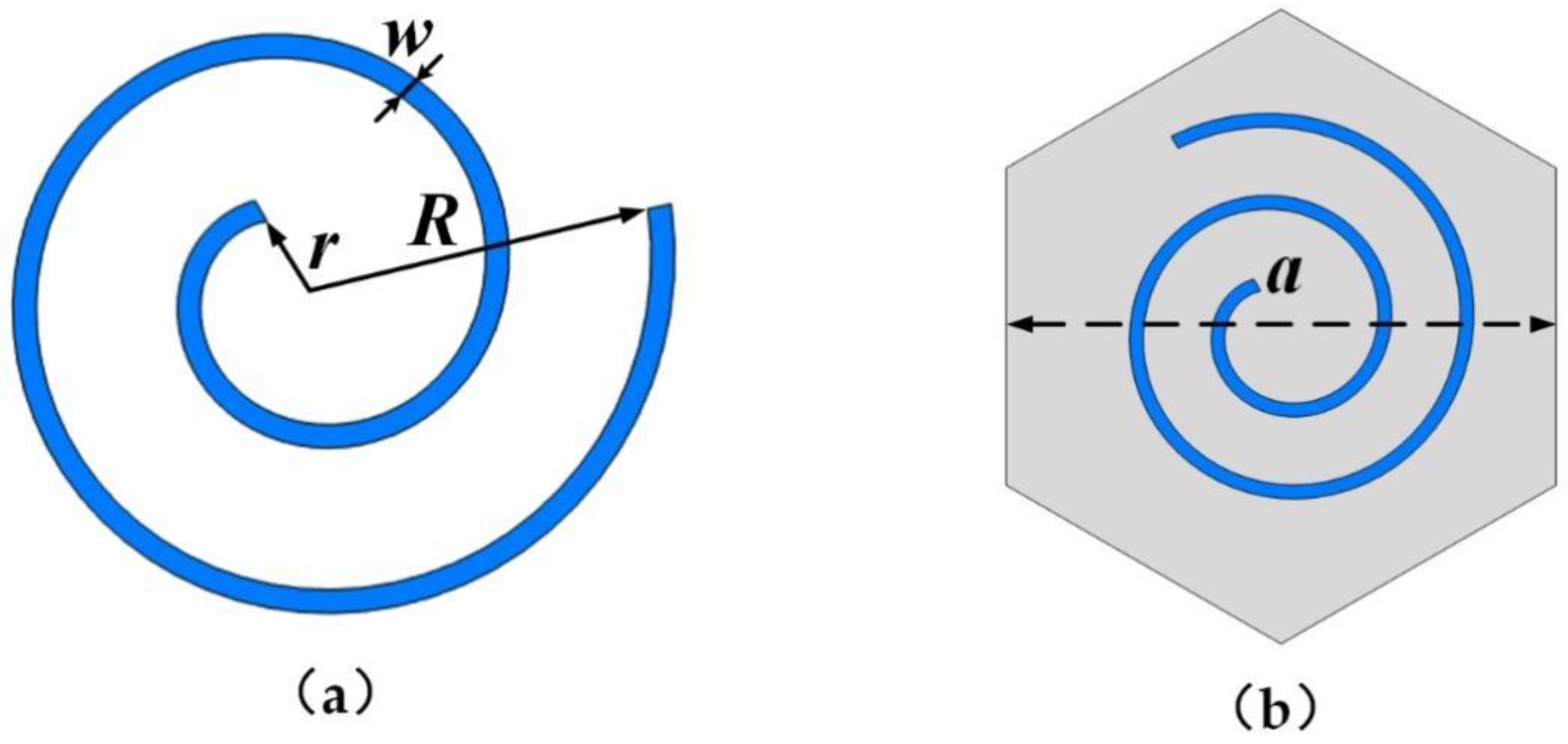
2. Structure Design
3. Results
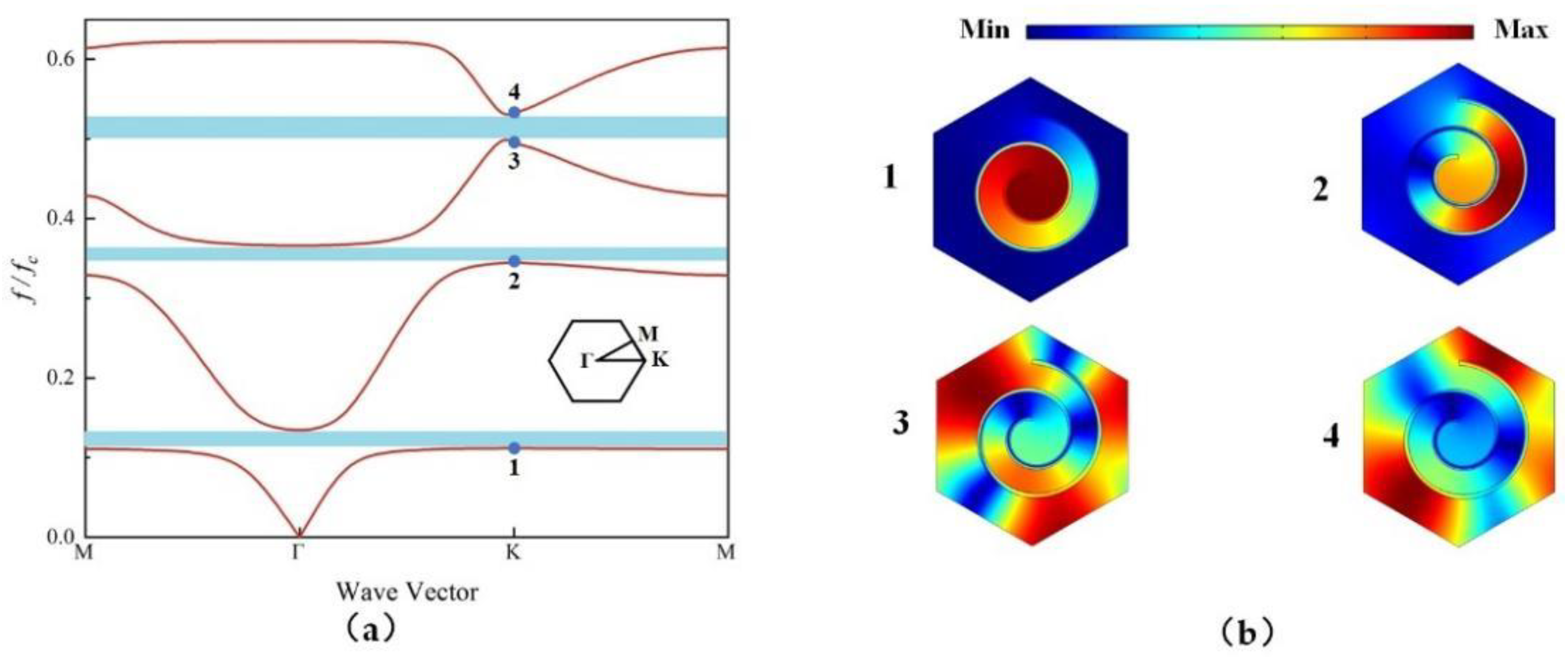
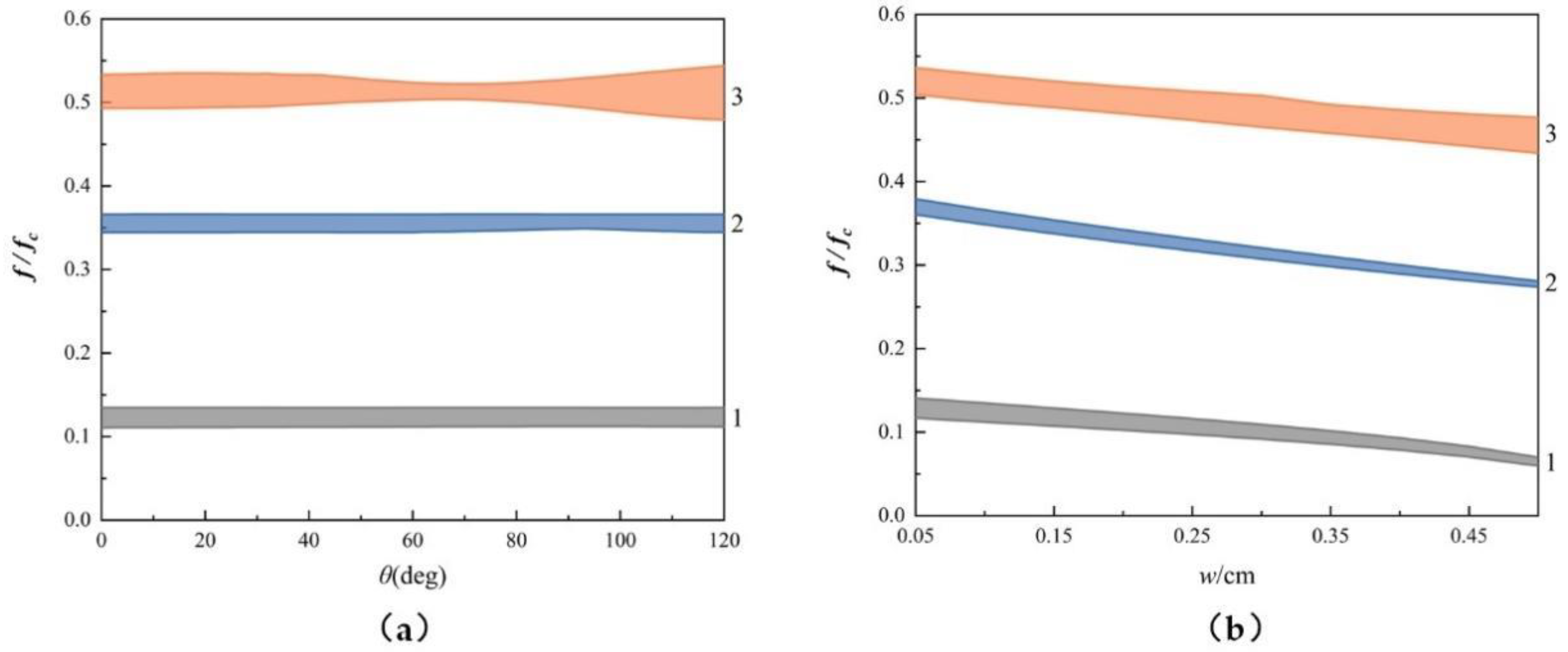
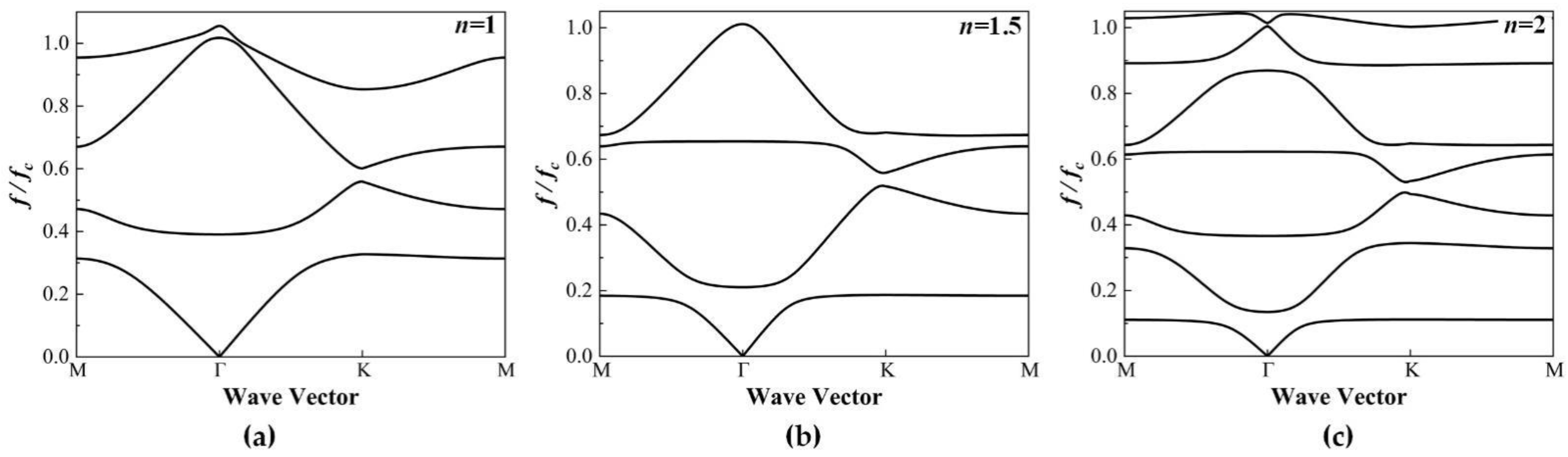
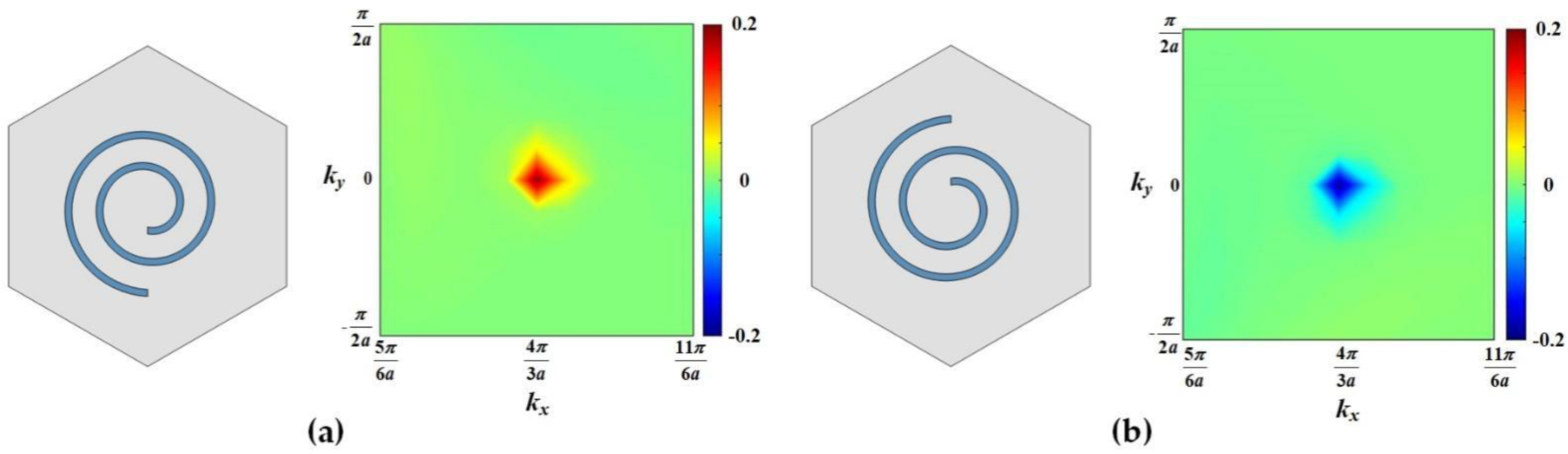
3.1. Band Structure
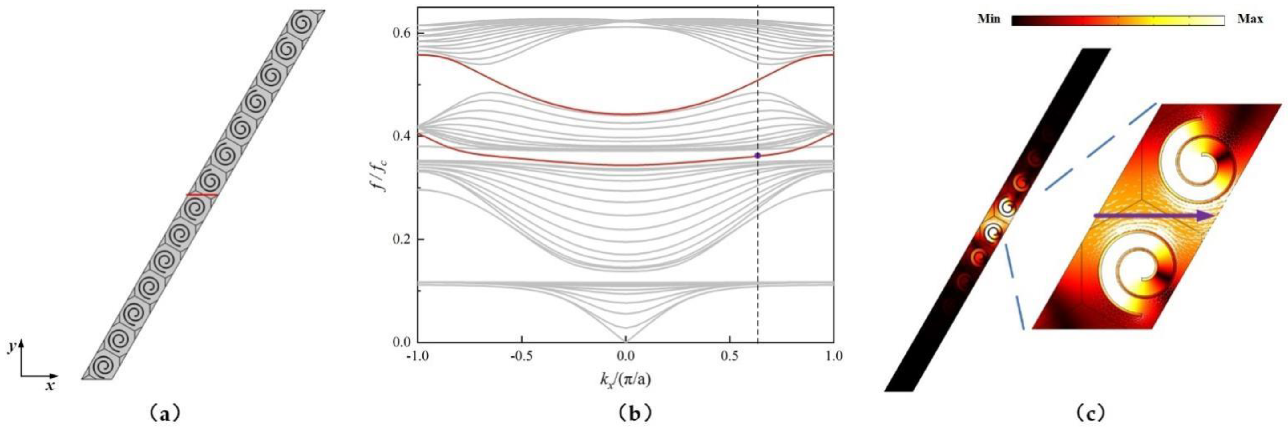
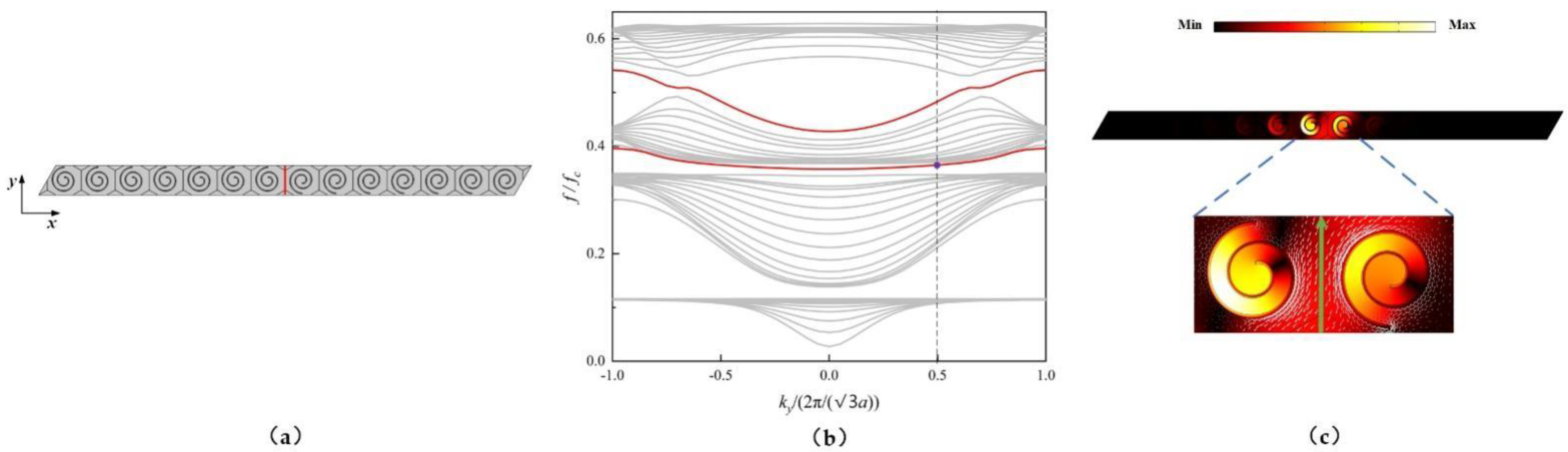
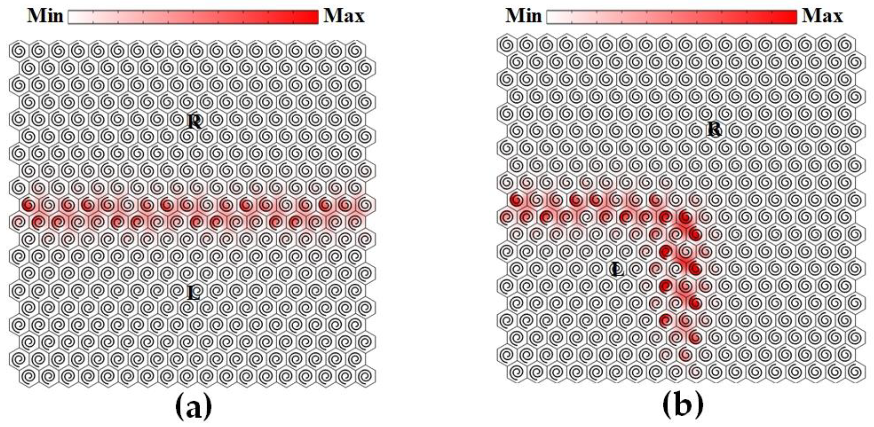
3.2. Topological Edge States
4. Conclusions
Author Contributions
Funding
Institutional Review Board Statement
Informed Consent Statement
Data Availability Statement
Conflicts of Interest
References
- Hasan, M.Z.; Kane, C.L. Colloquium: Topological insulators. Rev. Mod. Phys. 2010, 82, 3045–3067. [Google Scholar] [CrossRef] [Green Version]
- Qi, X.; Zhang, S. Topological insulators and superconductors. Rev. Mod. Phys. 2011, 83, 1057–1110. [Google Scholar] [CrossRef] [Green Version]
- Klitzing, K.V.; Dorda, G.; Pepper, M. New Method for High-Accuracy Determination of the Fine-Structure Constant Based on Quantized Hall Resistance. Phys. Rev. Lett. 1980, 45, 494–497. [Google Scholar] [CrossRef] [Green Version]
- Laughlin, R.B. Anomalous Quantum Hall Effect: An Incompressible Quantum Fluid with Fractionally Charged Excitations. Phys. Rev. Lett. 1983, 50, 1395–1398. [Google Scholar] [CrossRef] [Green Version]
- Kane, C.L.; Mele, E.J. Quantum Spin Hall Effect in Graphene. Phys. Rev. Lett. 2005, 95, 226801. [Google Scholar] [CrossRef] [PubMed] [Green Version]
- Bernevig, B.A.; Zhang, S.C. Quantum spin Hall effect. Phys. Rev. Lett. 2006, 96, 106802. [Google Scholar] [CrossRef] [Green Version]
- Yao, W.; Xiao, D.; Niu, Q. Valley-dependent optoelectronics from inversion symmetry breaking. Phys. Rev. B 2008, 77, 235406. [Google Scholar] [CrossRef] [Green Version]
- Ju, L.; Shi, Z.; Nair, N.; Lv, Y.; Jin, C.; Velasco, J.; Ojeda-Aristizabal, C.; Bechtel, H.A.; Martin, M.C.; Zettl, A.; et al. Topological valley transport at bilayer graphene domain walls. Nature 2015, 520, 650–655. [Google Scholar] [CrossRef]
- Zhang, X.; Xiao, M.; Cheng, Y.; Lu, M.; Christensen, J. Topological sound. Commun. Phys. 2018, 1, 97. [Google Scholar] [CrossRef] [Green Version]
- Pirie, H.; Sadhuka, S.; Wang, J.; Andrei, R.; Hoffman, J.E. Topological Phononic Logic. Phys. Rev. Lett. 2022, 128, 015501. [Google Scholar] [CrossRef]
- Wen, Z.; Zeng, S.; Wang, D.; Jin, Y.; Djafari-Rouhani, B. Robust edge states of subwavelength chiral phononic plates. Extrem. Mech. Lett. 2021, 44, 101209. [Google Scholar] [CrossRef]
- Qiu, H.; Xiao, M.; Zhang, F.; Qiu, C. Higher-Order Dirac Sonic Crystals. Phys. Rev. Lett. 2021, 127, 146601. [Google Scholar] [CrossRef] [PubMed]
- Yang, Z.; Peng, Y.; Li, X.; Zou, X.; Cheng, J. Boundary-dependent corner states in topological acoustic resonator array. Appl. Phys. Lett. 2020, 117, 113501. [Google Scholar] [CrossRef]
- Wang, Y.; Dong, Y.; Zhai, S.; Ding, C.; Luo, C.; Zhao, X. Reconfigurable topological transition in acoustic metamaterials. Phys. Rev. B 2020, 102, 174107. [Google Scholar] [CrossRef]
- Zheng, S.; Duan, G.; Xia, B. Progress in Topological Mechanics. Appl. Sci. 2022, 12, 1987. [Google Scholar] [CrossRef]
- Fleury, R.; Sounas, D.L.; Sieck, C.F.; Haberman, M.R.; Alù, A. Sound Isolation and Giant Linear Nonreciprocity in a Compact Acoustic Circulator. Science 2014, 343, 516–519. [Google Scholar] [CrossRef] [PubMed]
- Khanikaev, A.B.; Fleury, R.; Mousavi, S.H.; Alù, A. Topologically robust sound propagation in an angular-momentum-biased graphene-like resonator lattice. Nat. Commun. 2015, 6, 8260. [Google Scholar] [CrossRef] [PubMed]
- Ding, Y.; Peng, Y.; Zhu, Y.; Fan, X.; Yang, J.; Liang, B.; Zhu, X.; Wan, X.; Cheng, J. Experimental Demonstration of Acoustic Chern Insulators. Phys. Rev. Lett. 2019, 122, 014302. [Google Scholar] [CrossRef]
- He, C.; Ni, X.; Ge, H.; Sun, X.-C.; Chen, Y.-B.; Lu, M.-H.; Liu, X.-P.; Chen, Y.-F. Acoustic topological insulator and robust one-way sound transport. Nat. Phys. 2016, 12, 1124–1129. [Google Scholar] [CrossRef]
- Zhang, Z.; Wei, Q.; Cheng, Y.; Zhang, T.; Wu, D.; Liu, X. Topological Creation of Acoustic Pseudospin Multipoles in a Flow-Free Symmetry-Broken Metamaterial Lattice. Phys. Rev. Lett. 2017, 118, 084303. [Google Scholar] [CrossRef]
- Deng, Y.; Ge, H.; Tian, Y.; Lu, M.; Jing, Y. Observation of zone folding induced acoustic topological insulators and the role of spin-mixing defects. Phys. Rev. B 2017, 96, 184305. [Google Scholar] [CrossRef] [Green Version]
- Lu, J.; Qiu, C.; Ye, L.; Fan, X.; Ke, M.; Zhang, F.; Liu, Z. Observation of topological valley transport of sound in sonic crystals. Nat. Phys. 2016, 13, 369–374. [Google Scholar] [CrossRef] [Green Version]
- Xie, B.; Liu, H.; Cheng, H.; Liu, Z.; Tian, J.; Chen, S. Dirac points and the transition towards Weyl points in three-dimensional sonic crystals. Light Sci. Appl. 2020, 9, 201. [Google Scholar] [CrossRef] [PubMed]
- Tian, Z.; Shen, C.; Li, J.; Reit, E.; Bachman, H.; Socolar, J.E.S.; Cummer, S.A.; Jun Huang, T. Dispersion tuning and route reconfiguration of acoustic waves in valley topological phononic crystals. Nat. Commun. 2020, 11, 762. [Google Scholar] [CrossRef] [Green Version]
- Zhu, J.; Chen, T.; Chen, C.; Ding, W. Valley Vortex Assisted and Topological Protected Microparticles Manipulation with Complicated 2D Patterns in a Star-like Sonic Crystal. Materials 2021, 14, 4939. [Google Scholar] [CrossRef]
- Fang, W.; Han, C.; Chen, Y.; Liu, Y. Valley Hall Elastic Edge States in Locally Resonant Metamaterials. Materials 2022, 15, 1491. [Google Scholar] [CrossRef] [PubMed]
- Song, X.; Chen, T.; Chen, C.; Ding, W. Observation of frequency band-switchable topological edge modes using a 2 bit coding acoustic topological insulator. J. Phys. D Appl. Phys. 2021, 54, 255302. [Google Scholar] [CrossRef]
- Zhang, Z.; Cheng, Y.; Liu, X. Subwavelength higher-order topological insulator based on stereo acoustic networks. J. Appl. Phys. 2021, 129, 135101. [Google Scholar] [CrossRef]
- Xie, Y.; Wang, W.; Chen, H.; Konneker, A.; Popa, B.I.; Cummer, S.A. Wavefront modulation and subwavelength diffractive acoustics with an acoustic metasurface. Nat. Commun. 2014, 5, 5553. [Google Scholar] [CrossRef]
- Wang, X.; Mao, D.; Li, Y. Broadband acoustic skin cloak based on spiral metasurfaces. Sci. Rep. 2017, 7, 11604. [Google Scholar] [CrossRef] [Green Version]
- Zuo, S.; Wei, Q.; Tian, Y.; Cheng, Y.; Liu, X. Acoustic analog computing system based on labyrinthine metasurfaces. Sci. Rep. 2018, 8, 10103. [Google Scholar] [CrossRef] [PubMed]
- Jia, X.; Yan, M.; Hong, M. Sound energy enhancement via impedance-matched anisotropic metamaterial. Mater. Des. 2021, 197, 109254. [Google Scholar] [CrossRef]
- Orazbayev, B.; Kaina, N.; Fleury, R. Chiral Waveguides for Robust Waveguiding at the Deep Subwavelength Scale. Phys. Rev. Appl. 2018, 10, 054069. [Google Scholar] [CrossRef]
- Li, S.; Yang, J. Topological Transition in Spiral Elastic Valley Metamaterials. Phys. Rev. Appl. 2021, 15, 014058. [Google Scholar] [CrossRef]
- Zhao, R.; Xie, G.-D.; Chen, M.L.N.; Lan, Z.; Huang, Z.; Sha, W.E.I. First-principle calculation of Chern number in gyrotropic photonic crystals. Opt. Express 2020, 28, 4638–4649. [Google Scholar] [CrossRef] [PubMed] [Green Version]

Publisher’s Note: MDPI stays neutral with regard to jurisdictional claims in published maps and institutional affiliations. |
© 2022 by the authors. Licensee MDPI, Basel, Switzerland. This article is an open access article distributed under the terms and conditions of the Creative Commons Attribution (CC BY) license (https://creativecommons.org/licenses/by/4.0/).
Share and Cite
Yang, T.; Chen, M.; Xiao, B.; Liu, Y.; Jiang, H.; Wang, Y. Subwavelength Chiral Spiral Acoustic Metamaterials for a Robust Topological Acoustic Insulator. Appl. Sci. 2022, 12, 7778. https://doi.org/10.3390/app12157778
Yang T, Chen M, Xiao B, Liu Y, Jiang H, Wang Y. Subwavelength Chiral Spiral Acoustic Metamaterials for a Robust Topological Acoustic Insulator. Applied Sciences. 2022; 12(15):7778. https://doi.org/10.3390/app12157778
Chicago/Turabian StyleYang, Tao, Meng Chen, Boya Xiao, Yu Liu, Heng Jiang, and Yuren Wang. 2022. "Subwavelength Chiral Spiral Acoustic Metamaterials for a Robust Topological Acoustic Insulator" Applied Sciences 12, no. 15: 7778. https://doi.org/10.3390/app12157778
APA StyleYang, T., Chen, M., Xiao, B., Liu, Y., Jiang, H., & Wang, Y. (2022). Subwavelength Chiral Spiral Acoustic Metamaterials for a Robust Topological Acoustic Insulator. Applied Sciences, 12(15), 7778. https://doi.org/10.3390/app12157778