
Design of a CW BISOL RFQ for Three Kinds of High-Charge-State Ions Simultaneous Acceleration

 ,
,
Abstract
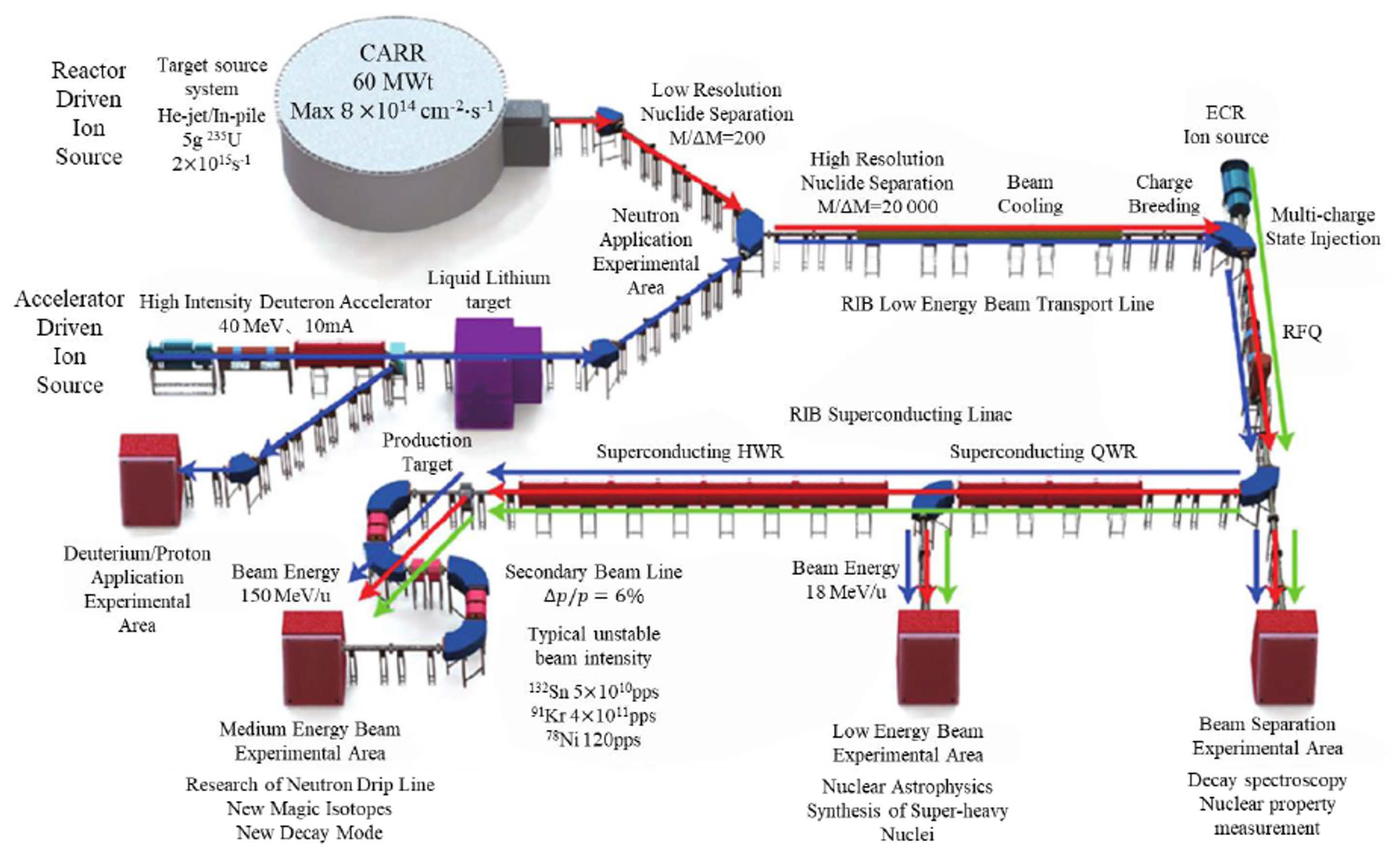
:1. Introduction
2. Beam Dynamics Design
2.1. Design Requirements and Beam Dynamics Scheme
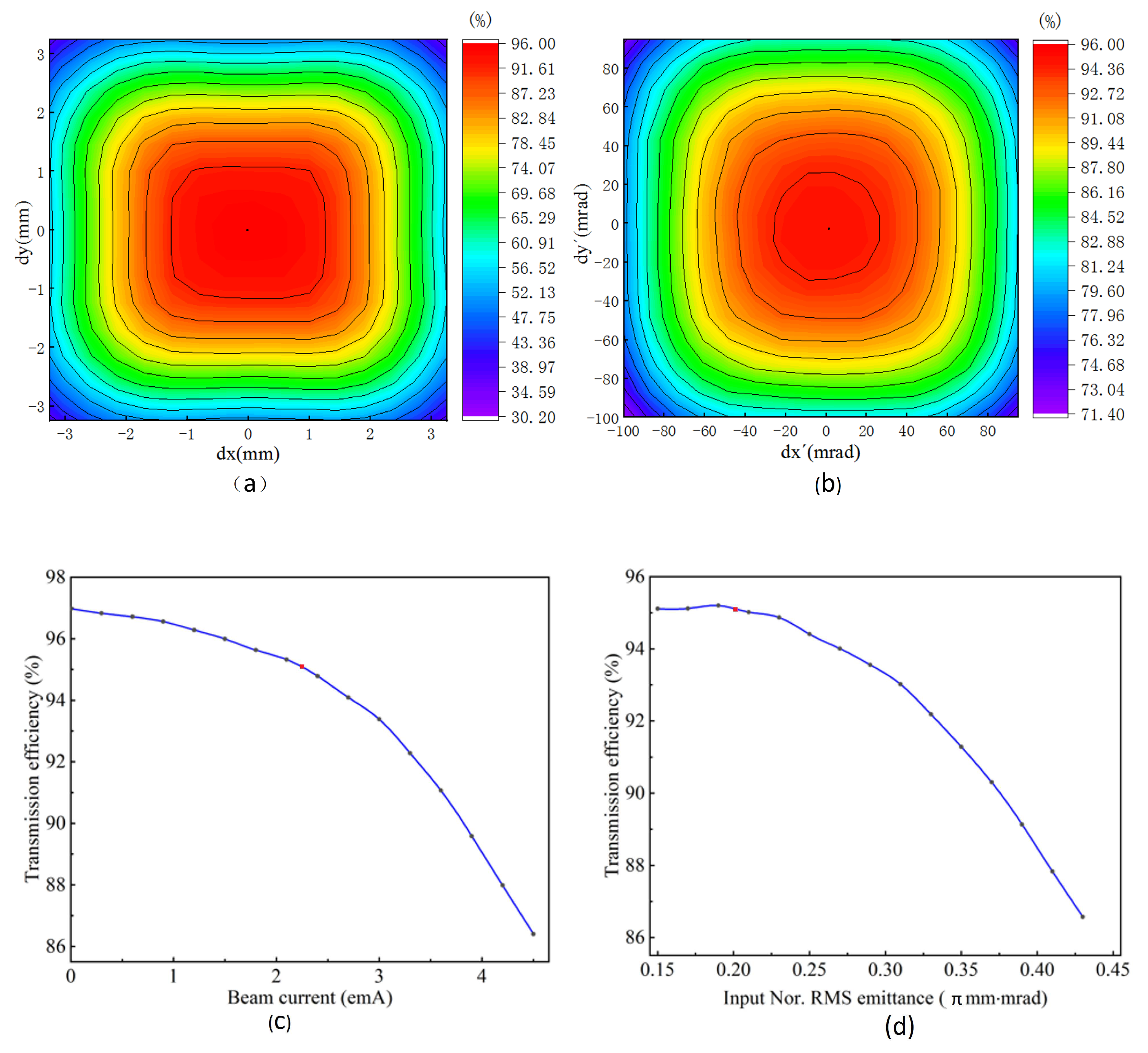
2.2. Tolerance Analysis
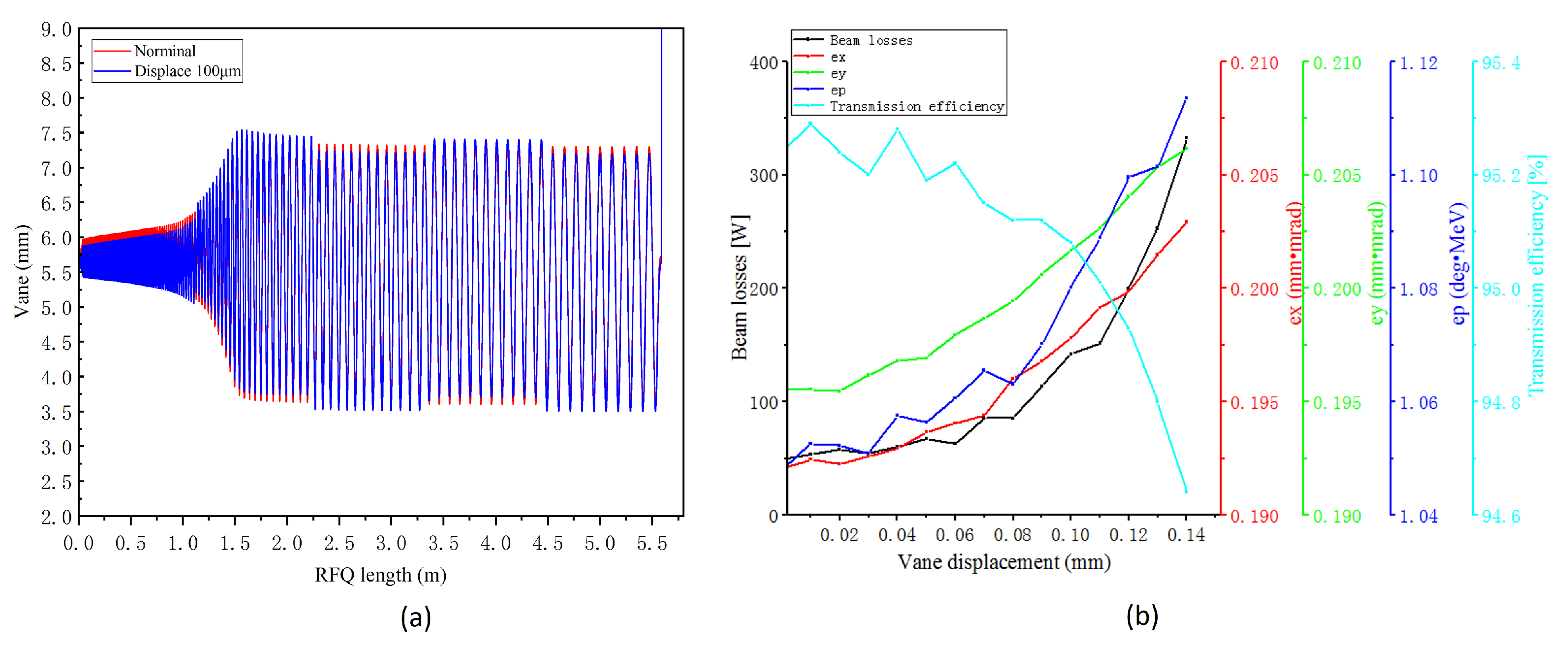
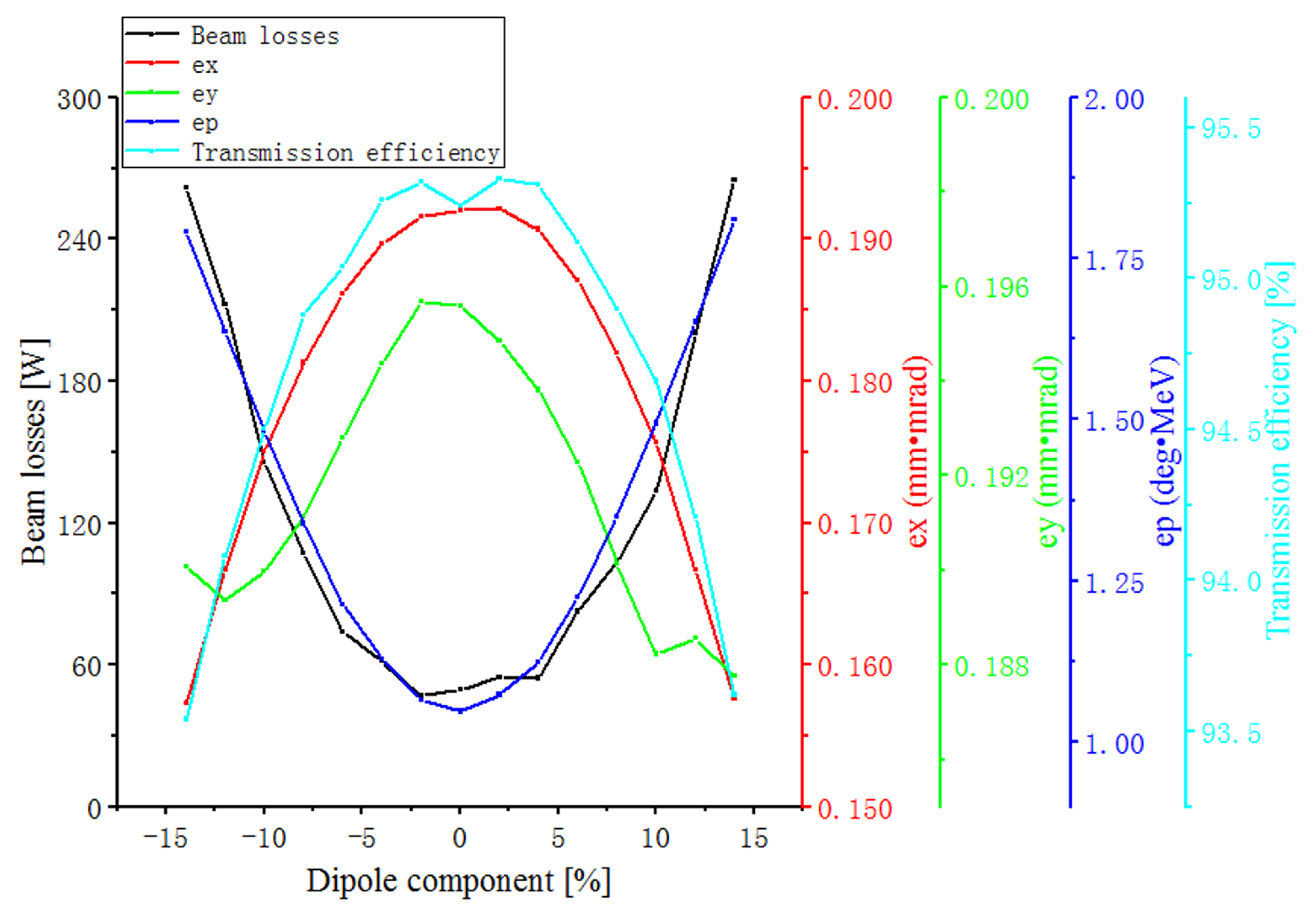
2.3. Errors Study
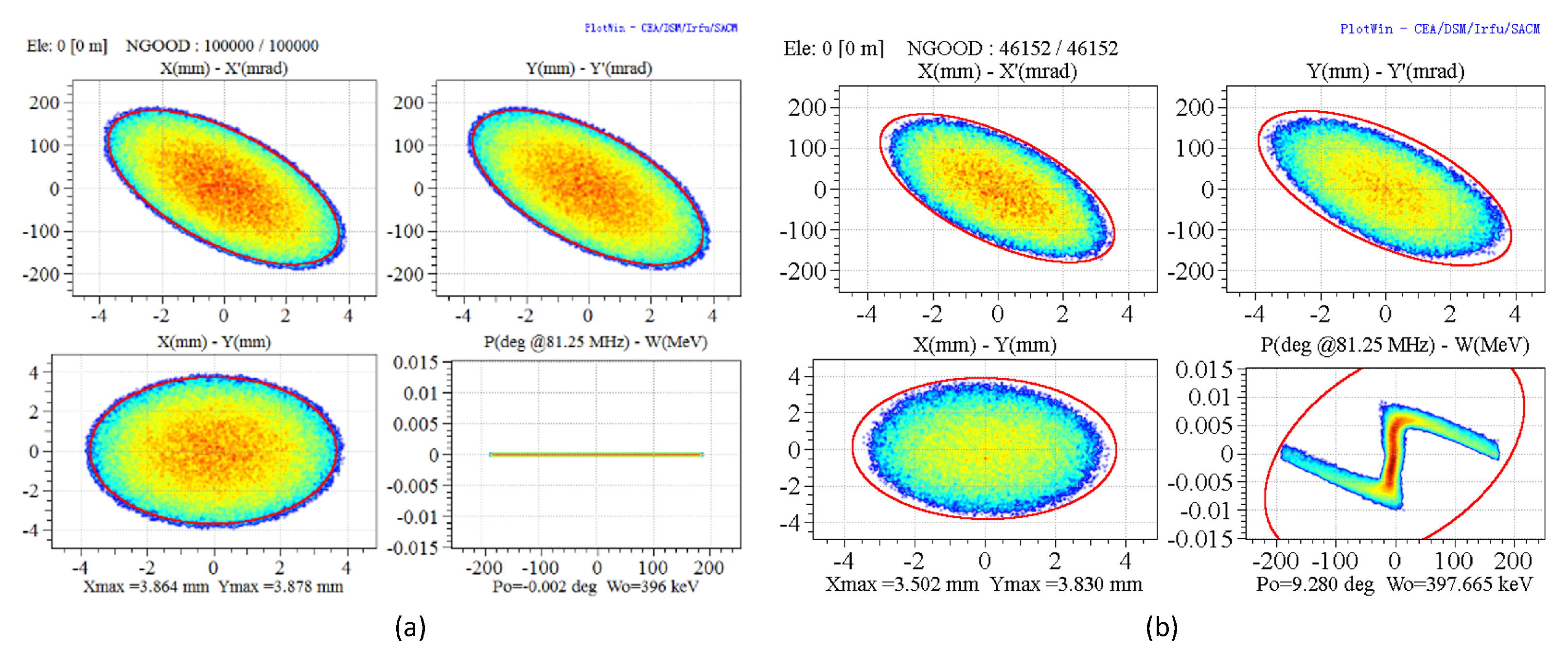
2.4. Three Kinds of High-Charge-State Ions Simultaneous Acceleration
3. Electromagnetic Design
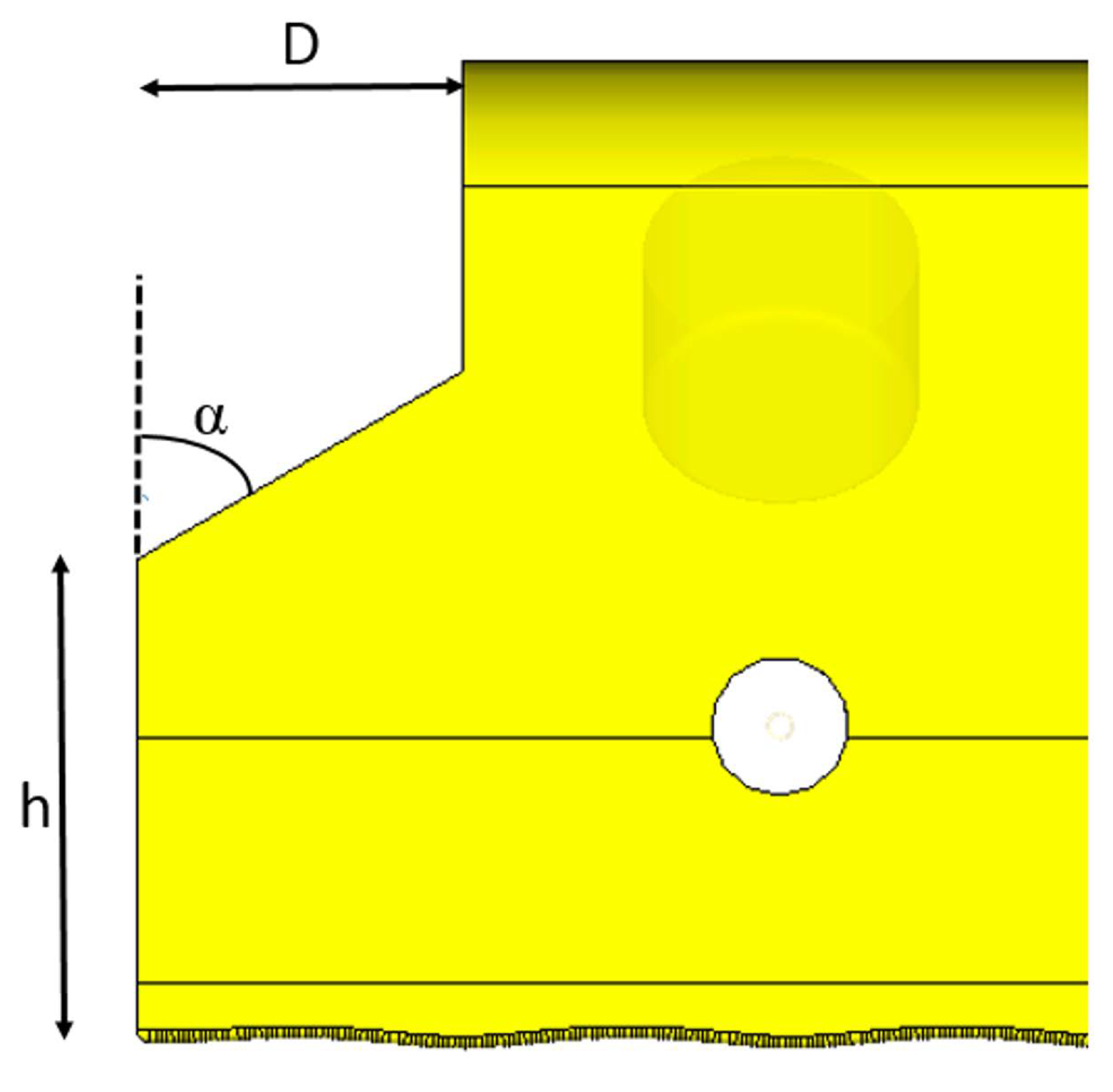
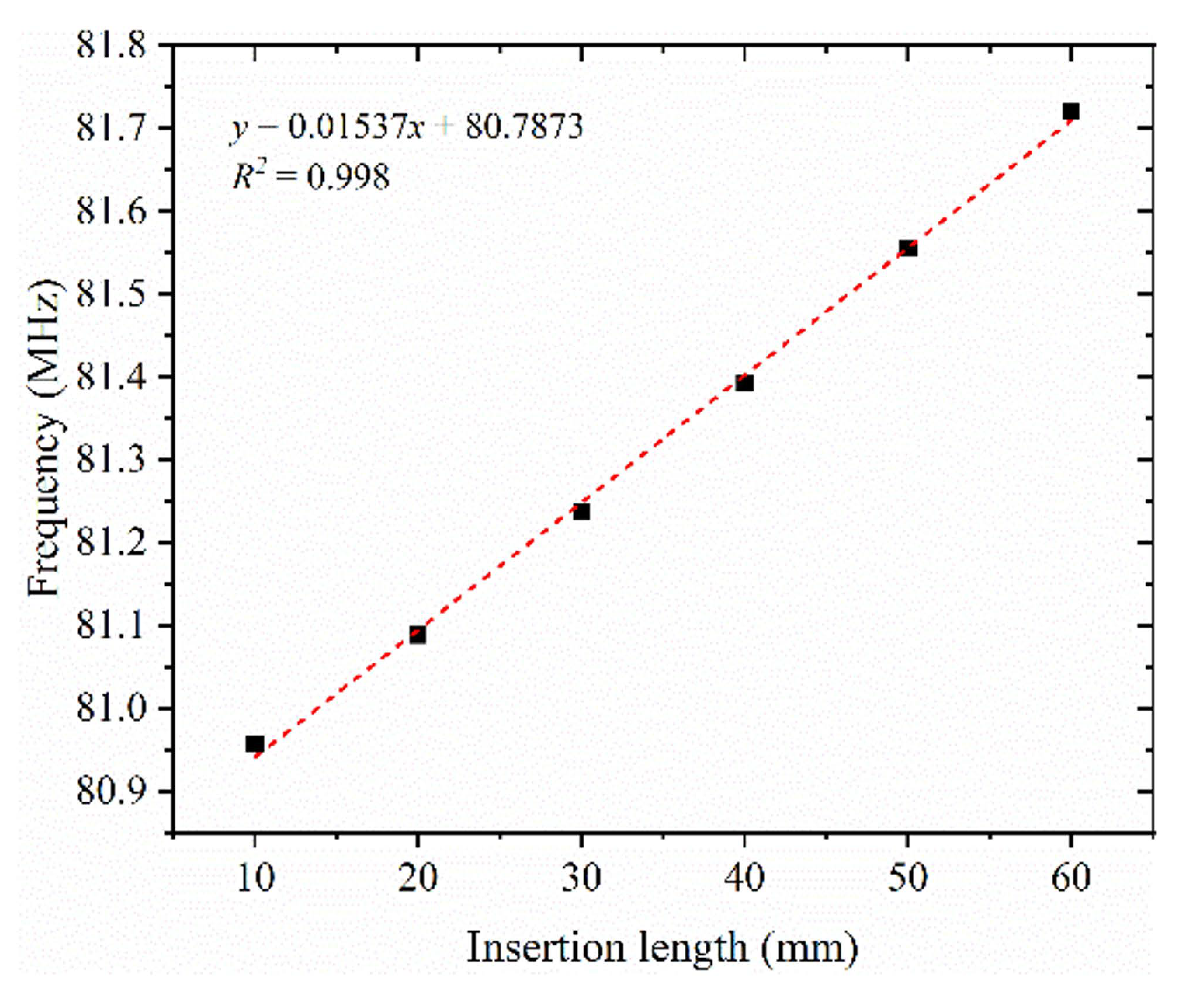
3.1. RFQ Field Tuning
3.2. Mode Separation
3.3. Rfq Full-Length Model Simulation
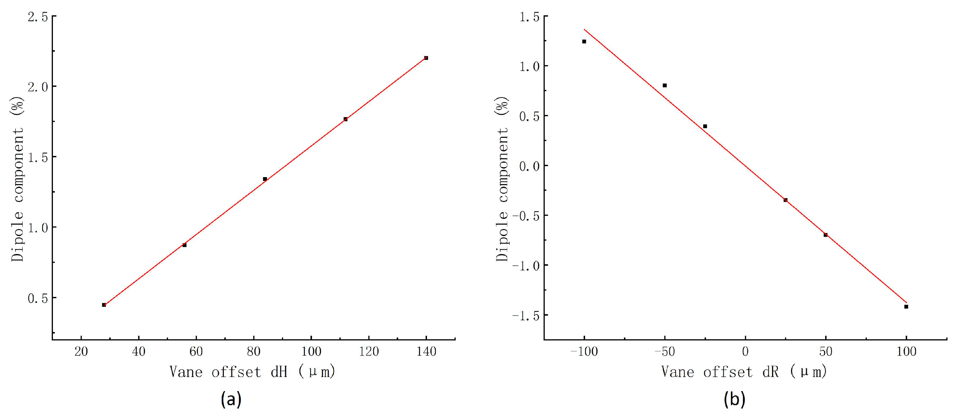
3.4. Errors Analysis
4. Multiple-Physical Analysis
5. Conclusions
Author Contributions
Funding
Acknowledgments
Conflicts of Interest
References
- Cui, B.; Gao, Y.; Ge, Y.; Guo, Z.; Li, Z.; Liu, W.; Peng, S.; Peng, Z.; Wang, Z.; Yan, S.; et al. The Beijing ISOL initial conceptual design report. Nucl. Instrum. Methods Phys. Res. Sect. Beam Interact. Mater. Atoms 2013, 317, 257–262. [Google Scholar] [CrossRef]
- Kamigaito, O. World-wide efforts on rare isotope and radioactive ion beams. In Proceedings of the IPAC2010, Kyoto, Japan, 23–28 May 2010; Volume 10. [Google Scholar]
- Gan, P.; Li, H.; Wang, Z.; Zhu, K.; Fu, Q.; Tan, Q.; Peng, Z.; Lu, Y. CW RFQ design and investigation for multi-charge-state acceleration of radioactive beams from BISOL. J. Instrum. 2018, 13, T08002. [Google Scholar] [CrossRef]
- Gerhard, P.; Barth, W.; Dahl, L.; Hartmann, W.; Schreiber, G.; Vinzenz, W.; Vormann, H. Experience with a 4-Rod CW Radio Frequency Quadrupole. In Proceedings of the LINAC2012, Tel-Aviv, Israel, 9–14 September 2012; pp. 825–827. [Google Scholar]
- Jeon, D.O.; Kim, H.J.; RAON Institute for Basic Science. Status of the RAON heavy ion accelerator project. In Proceedings of the LINAC2014, Geneva, Switzerland, 31 August–5 September 2014; p. 775. [Google Scholar]
- Ostroumov, P.; Mustapha, B.; Barcikowski, A.; Dickerson, C.; Kolomiets, A.; Kondrashev, S.; Luo, Y.; Paskvan, D.; Perry, A.; Schrage, D.; et al. Development and beam test of a continuous wave radio frequency quadrupole accelerator. Phys. Rev. Spec.-Top.-Accel. Beams 2012, 15, 110101. [Google Scholar] [CrossRef] [Green Version]
- Ren, H.; Pozdeyev, E.; Morris, D.; Zhao, S.; Morrison, P.; Walker, R.; Bultman, N.; Konrad, M.; Rao, X.; Brandon, J.; et al. Commissioning of the FRIB RFQ; IOP Publishing: Bristol, UK, 2018; Volume 1067, p. 052010. [Google Scholar]
- Kilpatrick, W. Criterion for vacuum sparking designed to include both rf and dc. Rev. Sci. Instrum. 1957, 28, 824–826. [Google Scholar] [CrossRef] [Green Version]
- Vossberg, M.; Schempp, A.; Zhang, C.; Dahl, L.; Barth, W. The new GSI HLI-RFQ for cw-operation. In Proceedings of the Linear Accelerator Conference, Tsukuba, Japan, 12–17 September 2010. [Google Scholar]
- Ferdinand, R.; Bertrand, P.; Di Giacomo, M.; Franberg, H.; Kamalou, O.; Lagniel, J.; Normand, G.; Savalle, A.; Varenne, F.; Uriot, D.; et al. Status of SPIRAL2 and RFQ beam commissioning. In Proceedings of the LINAC 2016, East Lansing, MI, USA, 25–30 September 2016; Volume 16, pp. 668–672. [Google Scholar]
- Liu, G.; Lu, Y.; He, Y.; Wang, Z.; Xiao, C.; Gao, S.; Yang, Y.; Zhu, K.; Yan, X.; Chen, J.; et al. Design of a CW high charge state heavy ion RFQ for SSC-LINAC. Nucl. Instrum. Methods Phys. Res. Sect. Accel. Spectrometers Detect. Assoc. Equip. 2013, 701, 186–193. [Google Scholar] [CrossRef]
- Li, C.; Zhang, Z.L.; Qi, X.; Xu, X.B.; He, Y.; Yang, L. Beam dynamics study of RFQ for CADS with a 3D space-charge-effect. Chin. Phys. C 2014, 38, 037005. [Google Scholar] [CrossRef]
- Schempp, A. Design of Compact RFQs. In Proceedings of the International Linear Accelerator Conference, Geneva, Switzerland, 26–30 August 1996. [Google Scholar]
- Crandall, K.; Stokes, R.; Wangler, T. RF quadrupole beam dynamics design studies. In Proceedings of the LINAC79, BNL, Montauk, NY, USA, 10–14 September 1979; Volume 51134, p. 205. [Google Scholar]
- Uriot, N.P.D. TraceWin. 2021. Available online: https://irfu.cea.fr/dacm/logiciels/codesdacm/tracewin/tracewin.pdf (accessed on 24 July 2022).
- Ji, Q. IMPACT-T: A 3D Parallel Particle Tracking Code in Time Domain. 2021. Available online: https://amac.lbl.gov/~jiqiang/IMPACT-T/index.html (accessed on 24 July 2022).
- Duperrier, R. TOUTATIS: A radio frequency quadrupole code. Phys. Rev. Spec.-Top.-Accel. Beams 2000, 3, 124201. [Google Scholar] [CrossRef] [Green Version]
- Ostroumov, P. FRIB Accelerator Science and Technology Challenges. 2021. Available online: https://meetings.triumf.ca/event/238/contributions/2954/attachments/2351/2667/Ostroumov-FRIB%20accelerator%20science%20and%20technology%20challenges.pdf (accessed on 24 July 2022).
- Ostroumov, P.; Pardo, R.; Zinkann, G.; Shepard, K.; Nolen, J. Simultaneous acceleration of multiply charged ions through a superconducting linac. Phys. Rev. Lett. 2001, 86, 2798. [Google Scholar] [CrossRef] [PubMed] [Green Version]
- Ostroumov, P.; Kondrashev, S.; Mustapha, B.; Scott, R.; Vinogradov, N. Analysis and recombination of multiple-charge-state beams from an electron cyclotron resonance ion source. Phys. Rev. Spec.-Top.-Accel. Beams 2009, 12, 010101. [Google Scholar] [CrossRef]
- Ostroumov, P.; Shepard, K. Multiple-charge beam dynamics in an ion linac. Phys. Rev. Spec.-Top.-Accel. Beams 2000, 3, 030101. [Google Scholar] [CrossRef] [Green Version]
- Staples, J. Reducing RFQ output emittance by external bunching. Part. Accel. 1989, 47, 191–199. [Google Scholar]
- Yang, Y.; Zhai, Y.; Tian, R.; Jin, X.; Wang, X.; Jing, L.; Xu, X.; Zhai, Y.; Tang, Y.; Zhang, B.; et al. Longitudinal emittance measurement for an external-bunching-based heavy-ion RFQ. Nucl. Instrum. Methods Phys. Res. Sect. A Accel. Spectrometers Detect. Assoc. Equip. 2022, 1029, 166457. [Google Scholar] [CrossRef]
- Chen, M.; Peng, Z.; Quan, S.; Zhu, F.; Liu, K.; Liu, Y.; Ouyang, D. Design study of multi-charge low energy beams transport for BISOL post accelerator. Nucl. Instrum. Methods Phys. Res. Sect. A Accel. Spectrometers Detect. Assoc. Equip. 2020, 981, 164453. [Google Scholar] [CrossRef]
- Systèmes, D. CST STUDIO SUITE. 2022. Available online: http://www.cst.com (accessed on 24 July 2022).
- Cornelius, W. CW operation of the FMIT RFQ accelerator. IEEE Trans. Nucl. Sci. 1985, 32, 3139–3143. [Google Scholar] [CrossRef] [Green Version]
- Schneider, J.D. A Review of High Beam Current RFQ Accelerators and Funnels. In Proceedings of the 1998 European Particle Accelerator Conference, Stockholm, Sweden, 22–26 June 1998. [Google Scholar]
- Brown, H.; Clifford, T.; Giordano, S.; Khiari, F.; McKenzie-Wilson, R.; Puglisi, M.; Warner, P. Design, Fabrication, and Testing of the BNL Radio Frequency Quadrupole Accelerator; Technical Report; Brookhaven National Lab: Upton, NY, USA, 1984. [Google Scholar]
- Andreev, V.; Parisi, G. Field Stabilization and End-Cell Tuning in a 4-vane RFQ. In Proceedings of the EPAC, London, UK, 27 June–1 July 1994; Volume 94, pp. 1300–1302. [Google Scholar]
- Young, L. Segmented resonantly coupled radio-frequency quadrupole (RFQ). In Proceedings of the International Conference on Particle Accelerators, Washington, DC, USA, 17–20 May 1993; pp. 3136–3138. [Google Scholar]
- Schempp, A. Overview of Recent RFQ Projects; LINAC: Victoria, BC, Canada, 2008; p. 41. [Google Scholar]
- Schmidt, J.; Maus, J.; Mueller, N.; Schempp, A.; Kester, O.; Haeuser, J. Tuning of the 4-Rod RFQ for MSU. In Proceedings of the IPAC2010, MOPD035, Kyoto, Japan, 23–28 May 2010. [Google Scholar]
- Leitner, D.; Benatti, C.; Krause, S.W.; Morris, D.; Nash, S.; Ottarson, J.; Perdikakis, G.; Portillo, M.; Rencsok, R.; Ropponen, T. Commissioning Results of the Rea RFQ at MSU. In Proceedings of the IPAC2011, San Sebastian, Spain, 4–9 September 2011; pp. 1912–1914. [Google Scholar]
- Bultman, N.K.; Pozdeyev, E.; Morgan, G.; Zhao, Q.; Yamazaki, Y.; Young, L.M.; Stovall, J. Design of the FRIB RFQ. In Proceedings of the IPAC 2015, Richmond, VA, USA, 3–8 May 2015. [Google Scholar]
- Ferdinand, R.; Bernaudin, P.E.; Bertrand, P.; Di Giacomo, M.; Ghribi, A.; Franberg, H.; Kamalou, O. Commissioning of SPIRAL2 CW RFQ and linac. In Proceedings of the Proceedings of the 8th International Particle Accelerator Conference (IPAC2017), Copenhagen, Denmark, 14–19 May 2017. [Google Scholar]
- Lu, L.; He, T.; Yang, L.; He, Y.; Zhao, H.; Xing, C.; Zhai, Y.; Shi, L.; Sun, L.; Li, J.; et al. Design and Beam Commissioning of the Leaf-Rfq; IOP Publishing: Bristol, UK, 2020; Volume 1401, p. 012013. [Google Scholar]
- Orduz, A.; Bontoiu, C.; Berjillos, A.; Dueñas, J.; Martel, I.; Garbayo, A.; AVS, E. Thermal and Structural Analysis of the 72.75 MHZ LINCE RFQ. In Proceedings of the IPAC 2015 6th International Particle Accelerator Conference, Richmond, VA, USA, 3–8 May 2015. [Google Scholar]
- Romanov, G.; Hoff, M.; Li, D.; Staples, J.; Virostek, S. Project X RFQ EM Design. In Proceedings of the IPAC2012, New Orleans, LA, USA, 20–25 May 2012. [Google Scholar]
- YANG Shi-Ming, T.W.Q. Heat Transfer, 4th ed.; Higher Education Press: Beijing, China, 2006. [Google Scholar]
- Perry, R.H. Engineering Manual, 3rd ed.; Mcgraw-Hill Book Company Press: New York, NY, USA, 1976. [Google Scholar]
- Chen, M.; Zhu, F.; Quan, S.; Hao, J.; Cheng, W.; Chen, S.; Cheng, A. Multi-Physcis Design Studies of A Superconducting Quarter-Wave Resonator at Peking University. In Proceedings of the 29th Linear Accelerator Conference (LINAC’18), Beijing, China, 16–21 September 2018; JACOW Publishing: Geneva, Switzerland, 2019; pp. 863–865. [Google Scholar]


| Parameter | Value |
|---|---|
| Reference particle | |
| Frequency (MHz) | 81.25 |
| Input beam energy (keV/u) | 3 |
| Output beam energy (keV/u) | 504 |
| Vane length (mm) | 5604 |
| Peak beam current (emA) | 2.2 |
| Duty factor (%) | 100 |
| Inter-vane voltage (kV) | 70 |
| Kilpatrick coefficient | 1.58 |
| Average aperture (mm) | 5.73 |
| Synchronous phase (deg) | −90∼−25 |
| Maximum modulation factor | 2.07 |
| Output transverse normalized rms emittance (mm·mrad) | 0.19 |
| Output longitudinal normalized rms emittance (keV/u·ns) | 0.20 |
| Transmission efficiency (%) | 95.6 (>95) |
| Parameter | PARMTEQ | TraceWin | Impact-T | Unit |
|---|---|---|---|---|
| Macro-particle number | 46,152 | - | ||
| Beam current | 2.2 | emA | ||
| Input nor. rms transverse emittance | 0.19/0.20 | mm·mrad | ||
| Input nor. rms longitudinal emittance | 0.20 | deg·MeV | ||
| Output energy | 0.505 | 0.504 | 0.505 | MeV/u |
| Output nor. rms transverse | 0.19/0.19 | 0.19/0.19 | 0.20/0.21 | mm·mrad |
| Output nor. rms longitudinal | 0.77 | 1.07 | 0.95 | deg·MeV |
| Transmission efficiency | 95.6 | 95.1 | 93.3 | % |
| Parameter | ,, | Unit |
|---|---|---|
| Input energy | 3 | keV/u |
| Beam current | 0.75/0.75/0.75 | emA |
| Input-normalized rms transverse emittance | 0.19/0.20 | mm·mrad |
| Output energy | 0.504 | MeV/u |
| Output normalized rms transverse emittance | 0.20/0.21 | mm·mrad |
| Output normalized rms longitudinal emittance | 0.38 | keV/u·ns |
| Transmission efficiency | 93.37 | % |
| Particle | ,, | ,, | ||
|---|---|---|---|---|
| Internal bunching | External bunching | Internal bunching | External bunching | |
| Output energy (keV/u) | 506 | 504 | 506 | 504 |
| Vane length (mm) | 6567 | 5604 | 6567 | 5604 |
| Input transverse normalized rms emittance mm·mrad) | 0.20 | 0.19/0.20 | 0.2 | 0.19/0.2 |
| Output transverse normalized rms emittance mm·mrad) | 0.23 | 0.19 | 0.191/0.196 | 0.2/0.21 |
| Output longitudinal normalized rms emittance (keV/u·ns) | 0.31 | 0.20 | 0.49 | 0.38 |
| Transmission efficiency (%) | 98.1 | 93.3 | 98.14 | 93.37 |
| (deg) | D (mm) | h (mm) | |
|---|---|---|---|
| Input | 60 | 130 | 180 |
| output | 60 | 118.5 | 180 |
| Code | HFSS | CST |
|---|---|---|
| TE210 (MHz) | 81.527 | 81.248 |
| TE110 (MHz) | 88.012 | 87.727 |
| TE111 (MHz) | 92.730 | 92.451 |
| TE211 (MHz) | 85.397 | 85.126 |
| Mode separation (MHz) (TE110) | 6.485 | 6.479 |
| Q ( S/m) | 16,908 | 17,749 |
| Power loss (kW) | 54 | 54 |
| Specific shunt impedance (k·m) | 511 | 511 |
| Part | Power Consumption (kW) | % |
|---|---|---|
| Wall | 19.82 | 36.70 |
| Vane | 28.57 | 52.91 |
| PISL | 3.23 | 5.99 |
| Tuner | 2.38 | 4.40 |
| All | 54 | 100 |
| ReA [32,33] | FRIB [34] | SPIRAL [10,35] | RISP [5] | LEAF [36] | BISOL | |
|---|---|---|---|---|---|---|
| frequency/MHz | 80.5 | 80.5 | 88.05 | 81.25 | 81.25 | 81.25 |
| Q/A | 1/2–1/5 | 1/3–1/7 | 1/2–1/3 | 1–1/7 | 1/2–1/7 | 1/5.74–1/6.29 |
| Input energy/(keV/u) | 12 | 12 | 20 | 10 | 14 | 3 |
| output energy/(keV/u) | 600 | 500 | 750 | 500 | 500 | 504 |
| mode separation/MHz | >2.4 | - | - | 1.5 | 5.54 (measured) | 6.5 |
| type | 4-rod | 4-vane | 4-vane | 4-vane | 4-vane | 4-vane |
| length/m | 3.50 | 5.04 | 5.08 | 4.95 | 5.95 | 5.60 |
| V/kV | 86.2 | 60–120 | 100–113 | 50–138 | 70 | 70 |
| power consumption/kW | 160 | 15–100 | 180 | 92.4 | 53.2 | 54 |
| Q | 4200 | 16,500 | 15,040 | 14,500 | 17,963 | 17,000 |
| transmission/% | 82 | >80 | >98 | 98 | 97.2 | 95.2 |
| Kp | 1.6 | 1.6 | 1.65 | 1.68 | 1.55 | 1.58 |
| Specific shunt Impedance [k·m] | 200 | - | - | 368 (estimated) | 551 | 511 |
| Frequency Shift | Dipole Component | |
|---|---|---|
| H | −0.03214 kHz/(µm) | 0.0151%/µm |
| R | −0.82722 kHz/µm | −0.0137%/µm |
Publisher’s Note: MDPI stays neutral with regard to jurisdictional claims in published maps and institutional affiliations. |
© 2022 by the authors. Licensee MDPI, Basel, Switzerland. This article is an open access article distributed under the terms and conditions of the Creative Commons Attribution (CC BY) license (https://creativecommons.org/licenses/by/4.0/).
Share and Cite
Han, M.; Lu, Y.; Wang, Z.; Peng, Z.; Liu, S.; Wei, T.; Xia, Y. Design of a CW BISOL RFQ for Three Kinds of High-Charge-State Ions Simultaneous Acceleration. Appl. Sci. 2022, 12, 7761. https://doi.org/10.3390/app12157761
Han M, Lu Y, Wang Z, Peng Z, Liu S, Wei T, Xia Y. Design of a CW BISOL RFQ for Three Kinds of High-Charge-State Ions Simultaneous Acceleration. Applied Sciences. 2022; 12(15):7761. https://doi.org/10.3390/app12157761
Chicago/Turabian StyleHan, Meiyun, Yuanrong Lu, Zhi Wang, Zhaohua Peng, Shuo Liu, Tianhao Wei, and Ying Xia. 2022. "Design of a CW BISOL RFQ for Three Kinds of High-Charge-State Ions Simultaneous Acceleration" Applied Sciences 12, no. 15: 7761. https://doi.org/10.3390/app12157761
APA StyleHan, M., Lu, Y., Wang, Z., Peng, Z., Liu, S., Wei, T., & Xia, Y. (2022). Design of a CW BISOL RFQ for Three Kinds of High-Charge-State Ions Simultaneous Acceleration. Applied Sciences, 12(15), 7761. https://doi.org/10.3390/app12157761