Article

Simulations of Extrusion 3D Printing of Chitosan Hydrogels

1
The State Key Laboratory of Fluid Power and Mechatronic Systems, School of Mechanical Engineering, Zhejiang University, Hangzhou 310027, China
2
Mechanical Engineering School, Iran Sharif University of Technology, International Campus, Kish 79417-76655, Iran
3
Key Laboratory of 3D Printing Process and Equipment of Zhejiang Province, School of Mechanical Engineering, Zhejiang University, Hangzhou 310027, China
*
Author to whom correspondence should be addressed.
Appl. Sci. 2022, 12(15), 7530; https://doi.org/10.3390/app12157530
Submission received: 31 May 2022 / Revised: 20 July 2022 / Accepted: 23 July 2022 / Published: 27 July 2022

Abstract

:
Extrusion-based three-dimensional (3D) printing has recently become a major field that provides significant benefits, as it is principally employed to fabricate 3D scaffolds, exploiting soft biomaterials. The 3D printing hydrogel-based ink requires crucial properties, such as printability and printing fidelity to fabricate the appropriate structure. However, it typically uses trial and error techniques to achieve a three-dimensional structure, which wastes material and time. This study employed multiphysics simulation to predicate the potential printability of chitosan hydrogel as a desirable biomaterial used in tissue engineering. The flow was presumed to be laminar and two-phased in the simulations. Furthermore, the impact of different velocities and viscosities in extrusion-based chitosan 3D printing was investigated. Moreover, the model validation of the printed chitosan hydrogel was investigated to confirm the simulation outcomes for high-quality printing. The effect of different printing settings was studied during the experimental test. The results obtained from the simulation and experiments provide information for deciding the optimum parameters for printing chitosan-based ink with high quality.

1. Introduction

Three-dimensional (3D) printing, also referred to as additive manufacturing, is a type of rapid prototyping technology [1,2,3,4]. Extrusion-based 3D printing has broad application prospects in the area of tissue engineering [5,6,7,8], drug delivery [9,10], and medical equipment [11,12,13,14]. Hydrogel-based 3D printing combines additive manufacturing methods and hydrogel biomaterial [15,16,17,18]. Degradability, biocompatibility, printability, mechanical strength, and chemical modification level affect the quality of 3D printing hydrogel-based ink [19,20,21]. The printability of hydrogel is one of the important factors in 3D printing [22,23].
Among hydrogels, chitosan is a polysaccharide material from the deacetylation of chitin [24,25,26,27]. The printed chitosan hydrogel requires some ability to construct a complex structure and high resolution devoid of structural defects [28]. Consequently, chitosan has more applications than the common materials in biological tissues due to its exceptional biocompatibility, biological activity, safety, and inexpensive printing production [29,30]. Additionally, chitosan can be desirable for hydrogel fabrication in soft tissue regeneration [31].
Therefore, chitosan can be preferred for hydrogel fabrication in tissue engineering applications [32,33,34,35]. Numerical simulation helps prevent wasting material and time in chitosan printing. In this way, some researchers have reported the simulation modeling of hydrogel-based 3D printing. For example, Chiesa et al. [36] inferred that the modeling 3D bioprinting SAPHs and printing setups resulted in successful printing. Göhl et al. [37] investigated the impact of different printing parameters and examined the printing process using computational fluid dynamics simulation, which reduces the time and cost of bio-ink. This study examines the influence of cell viability on 3D bioprinting. Guo et al. [38] compare the screw and syringe-based extrusion 3D printing techniques by employing a computational simulation model and printing experiment. Zhu et al. [39] reported mathematical simulations of cell scaffold fabrication. The glucose and TGF-β2 with mass transfer in a wall vessel bioreactor (RWVB) and cell culture were simulated using the computational fluid dynamic (CFD) technique. The findings paved the way for fabricating tissue-engineered cartilage using chitosan/gelatin hydrogel. To simulate extrusion-based 3D printing, Behdani et al. [40] studied a numerical model of temperature-dependent non-Newtonian viscosity. A polylactic acid melt flow as a non-isothermal power-law fluid is used in the numerical simulation. The findings reveal that the nozzle’s temperature can influence the shape strand and surface topography.
Moreover, Wu et al. [33,41] reported that 3D printing of chitosan hydrogel in the air causes shrinkage during printing and the formation of chitosan hydrogel. They immersed dry fabricated chitosan hydrogel in a sodium hydroxide (NaOH) solution for the neutralization process and attempted to reduce shrink-induced shape deformation. However, because the printing and incubation processes are independent, it is difficult to get the fabrication done in a short time. For this reason, the chitosan hydrogel is usually prepared via acid solvent and chemical crosslink. A novel chitosan hydrogel was used in this study. The new chitosan ink is dissolved in an alkaline aqueous solution called the green technique and rapid fabrication [42]. Therefore, the innovation of this study is a CFD simulation of the 3D printing of a novel chitosan ink. An experimental test supports this finding and paves the way for the optimization of the printing step and saving time and material in the 3D printing process. This simulation was conducted in COMSOL Multiphysics software version 5.2.a (Hangzhou, China). Because the simulation results of the extrusion formation gave the optimal parameters for the printability fidelity of chitosan ink, the main goal of these simulations was to theoretically demonstrate the extrusion-based 3D printing of new chitosan hydrogel. Therefore, theoretical techniques were used to describe the fiber formation in the 3D printing and modeling simulation of chitosan 3D printing. The simulations were based on the laminar two-phase flow level set. The two phases were made up of a nozzle, as shown in Figure 1, where the continuous phase of air impinges on the dispersive phase from side channels while the inner fluid, or dispersive phase (chitosan ink), enters through a vertical channel. Furthermore, the impact of important variables such as the inlet velocity and hydrogel viscosity on the chitosan extrusion 3D printing was studied. Ultimately, the simulation results help reduce time and cost in the printing fidelity of chitosan-based ink in the experimental test process. The findings of the experimental test are shown together with the fidelity printability of novel chitosan hydrogel.

2. Fundamental and Modeling

The extrusion-based 3D printing involves depositing ink to construct the 3D structure layer by layer, with a group of sub-μm to mm scale [43]. However, a chitosan-based 3D printing numerical simulation aids in studying the flow characteristics and design enhancement of chitosan-based inks. Therefore, the scaling properties and the mechanism of chitosan-based ink were studied for various velocities and viscosities. Usually, with the 3D printing of hydrogel, other variables (such as substrate temperature) are also important. However, in such a novel material as chitosan hydrogel, the temperature of the substrate was maintained constant at 60 °C. Hence, this novel chitosan hydrogel requires a unique condition for 3D printing in which the chitosan ink is a stable solution kept at a low temperature (5 °C). In contrast, once heated, the chitosan chains will self-assemble to gelation. Based on this principle, the effect of viscosity concentration and velocity parameters in the CFD simulation were studied. The variables employed in the CFD simulation are attached in Support Information SI1 and SI2.
The presented simulation falls into the computational fluid dynamic (CFD) category, as the forces and torques and their effects on the motion were studied. Examples of these simulations include the flow simulation through the nozzle by creating a representative geometry, and employing the phase-field technique between the fluid and air. Since the computational fluid dynamics (CFD) simulations provide insight into the 3D printing process, parameters such as the surface tension, viscosity, and velocity will affect the motion. For this reason, the study of viscosity and velocity is important for extruding ink from the nozzle.
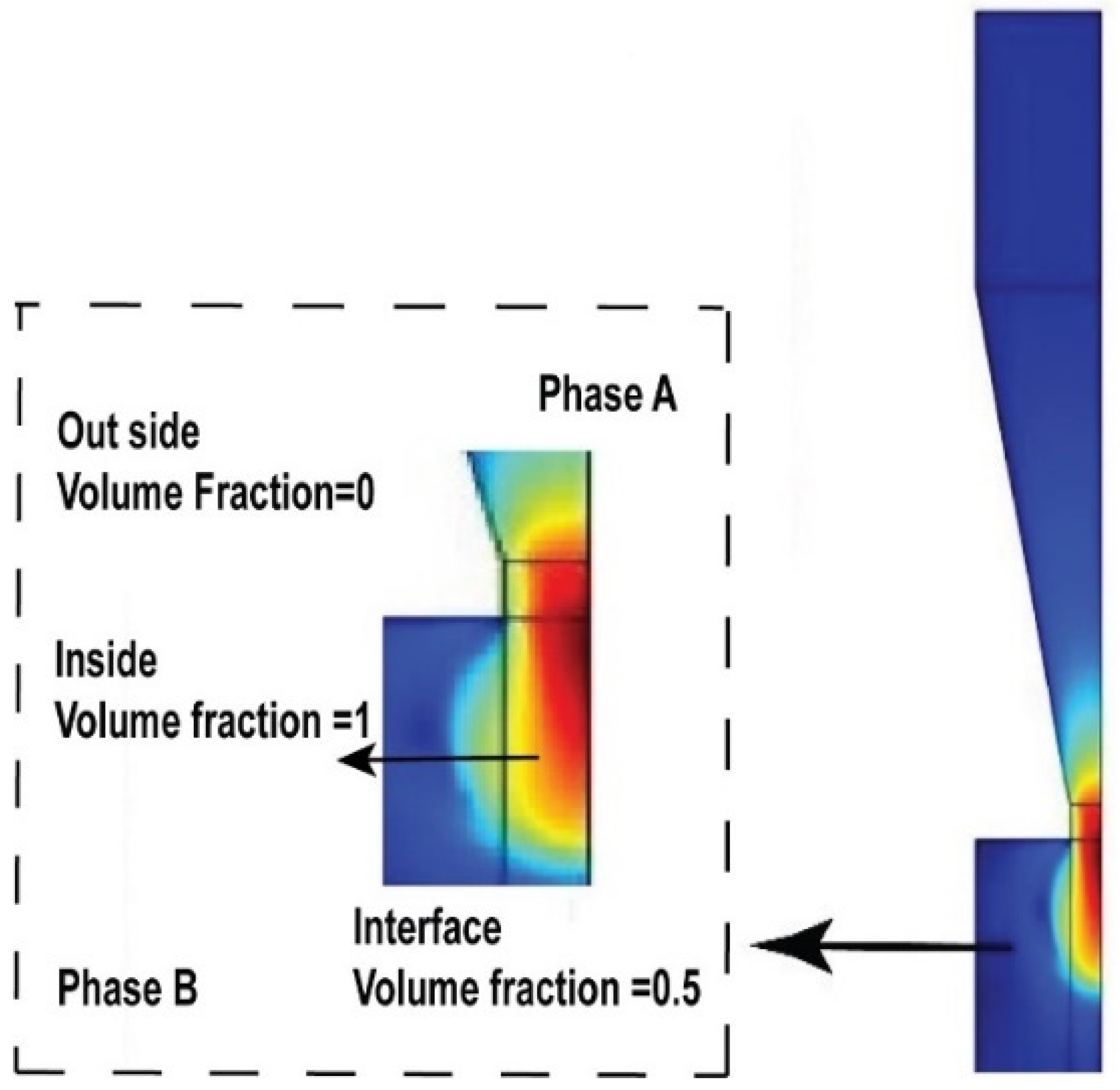
The two-phase flow level set was used to accomplish the objectives of this numerical simulation. This technique represents the interface with a smooth function. Therefore, it is much more convenient to compute the curvature and surface tension forces and regulate the formation of an extrusion fluid from the nozzle. Furthermore, the level set method facilitates the tracking of shapes that change the topology. For instance, when a shape divides into two, it develops a nozzle and may reverse the operations. These properties make the level set technique great for modeling time-varying objects, such as the extrusion fluid surrounding air. Hence, it is more appropriate to model the extrusion system inside air. The problem described in this study is straightforward to set up with the two-phase flow, laminar, and level set application modes. The application mode sets up a momentum transport equation, a continuity equation, and a level set equation. Thus, the 0.5 contours of the level set function defined the fluid interface. The application mode employs the following equations.

3. Theoretical Model

As previously mentioned, different factors, such as the inlet velocity, nozzle diameter, and viscosity, can influence the printing quality during the printing process. The chitosan-based ink 3D printing demonstrates shear-thinning behavior—the shear-thinning changes with temperature and shear rate. Hence, Equation (1) states that shear stress determines the fluid viscosity with gradual deformation.
η = τ
where η is the viscosity, τ (Pa) is the shear stress, and ẏ ( s 1 ) is the shear rate. Additionally, the shear rate behavior affects the viscosity of the fluid. The Carreau Yasuda model is the simplest approach to explain this process. This model determines the fluid viscosity at a shear rate. The viscosity equations of the Carreau model are expressed in Equations (2) and (3).
η = k n 1 f o r   s h e a r t h i n n i n g   f l u i d s   ( n < 1 )
η = η n f + η 0 η i n f 1 + λ a n 1 a
where K is the consistency coefficient, η 0 is the fluid viscosity when the shear rate is zero, η i n f is the fluid viscosity in the case of infinite shear rate, λ is the relaxation time index, a is a dimensionless parameter, ẏ is the shear rate, and n is the shear-thinning index.
The viscosity decreases by raising the shear rate when the shear-thinning of fluid n is less than one (n < 1). Conversely, when the shear-thinning of fluids n is greater than one (n > 1), the viscosity increases by raising the shear rate. In Newtonian fluids, when n = 1, the shear rate does not affect the fluid viscosity.
In this study, the interface of two immiscible fluids was tracked. As there is more than one phase in this system, the numerical simulation of the two-phase flow model solves the system. The two fluids’ level set and phase-field were solved using the general Navier–stokes equation, which is given by the following:
ρ u t + p u · u = · p I + μ u + u T 2 3 μ T · u I + p g + F s t + F
where ρ denotes the density kg / m 3 , u is the velocity m / s , t represents the time s , η is the dynamic viscosity Pa · s , p is the pressure Pa such that p = 0 , and F s t denotes the surface tension force N / m 3 . The level set technique explains the fluid interface. Therefore, a continuity equation solves the level set technique:
ρ · u = 0
ρ u   · u = · ρ I + k + F
u t = · p I + μ u + u T + p g + F s t + F
The two-phase flow and laminar level set modes set up the momentum transport. The COMSOL Multiphysics can solve the transport equation to track the interface of two fluids employing the following equation:
ϕ t + u · ϕ = γ ϕ 1 ϕ ϕ ϕ ε ϕ
where ϕ is the level set function interface (0.05), γ and ε are the numerical stabilization parameters, and u is the flow velocity.
In this model, the continuum air contour is set as 0, and the dispersed fluid ink contour is set as 1 of the level set function. γ represents the start variable. It is an estimated value of the maximum speed occurring. Because the flow speed is not always known in advance, an initial computation must find a correct value. ε is the controlling interface thickness. It is the maximum element size in the subdomains passed by the interface. Based on this calculation, γ is 1 m/s, and ε is ( t p f . h m a x ) 2 m. The smooth function is used to transit in the fluid interface region.
Additionally, the volume fraction is a variable that regulates the interface. In a two-phase flow level set simulation, for the viscosity and density adjustment, the following equations are employed:
F s t = σ δ k n i n t + δ s σ
K = · n i n t ; s = 1 n i n t n i n t T
ρ = ρ 1 + ρ 2 ρ 1 φ
μ = μ 1 + μ 2 μ 1 φ
where the volume fraction is denoted by φ ,   ρ 1 and ρ 2 are the densities of phases 1 and 2, respectively, and μ 1 and μ 2 are the viscosities of phases 1 and 2, respectively. Subsequently, the volume fraction is computed, adjusting the interface between the two-phase fluids. When φ = 0, the volume fraction is blue; this means that the blue part presents the air in a simulation of two-phase fluids. When the volume fraction is 1 ( φ = 1), the red shows the hydrogel ink in the simulation system. Additionally, the viscosity and density of ink change when hydrogel ink is extruded from a nozzle. This function is computed by Equations (11) and (12). Consequently, viscosity and density calculation results are repeated in all equations to clarify new values. This process is maintained until the completion of the simulation. The boundary types of entrances A and B are set as the inlet type, as shown in Figure 2. The boundary condition is the laminar flow with volume flow velocities with ink and air, respectively.
Figure 3 presents the boundary conditions (Equation (13)) of the model. The boundary of inlet A (ink) is set as the laminar flow, as in the following equation;
u · n = 0
F w a l l = σ δ ( n · n i n t cos θ w ) n i n t μ β u u · n n
n · ε i s ϕ ϕ 1 ϕ ϕ ϕ = 0
where the boundary condition of inlet A (ink), the volume fraction of the ink is defined by ϕ = 0 . M. Moreover, the volume fraction of air is adjusted to ϕ = 1 . The boundary condition of the outlet was normal stress without viscosity. The wetted wall boundary condition is applied to all the solid boundaries with the contact angle specified; the contact angle is 3 axes ( θ w = 3 * p i / 4 ) in the junction of the break dispread and continuous phase. Moreover, the initial interface is set to a solid type in the channel, and the ink velocity is 1 [m/s], and the pressure is zero ( p = 0 pa).

4. Results and Discussion

4.1. Chitosan-Based Ink Characterization in 3D Printing Modeling

This section presents the simulation results and ink characterization in 3D printing models. It shows the results obtained using a numerical simulation in which a 3D printing device was used to extrude chitosan ink from a nozzle. The effect of different velocities and viscosities on extrusion formation in 3D printing was also studied.
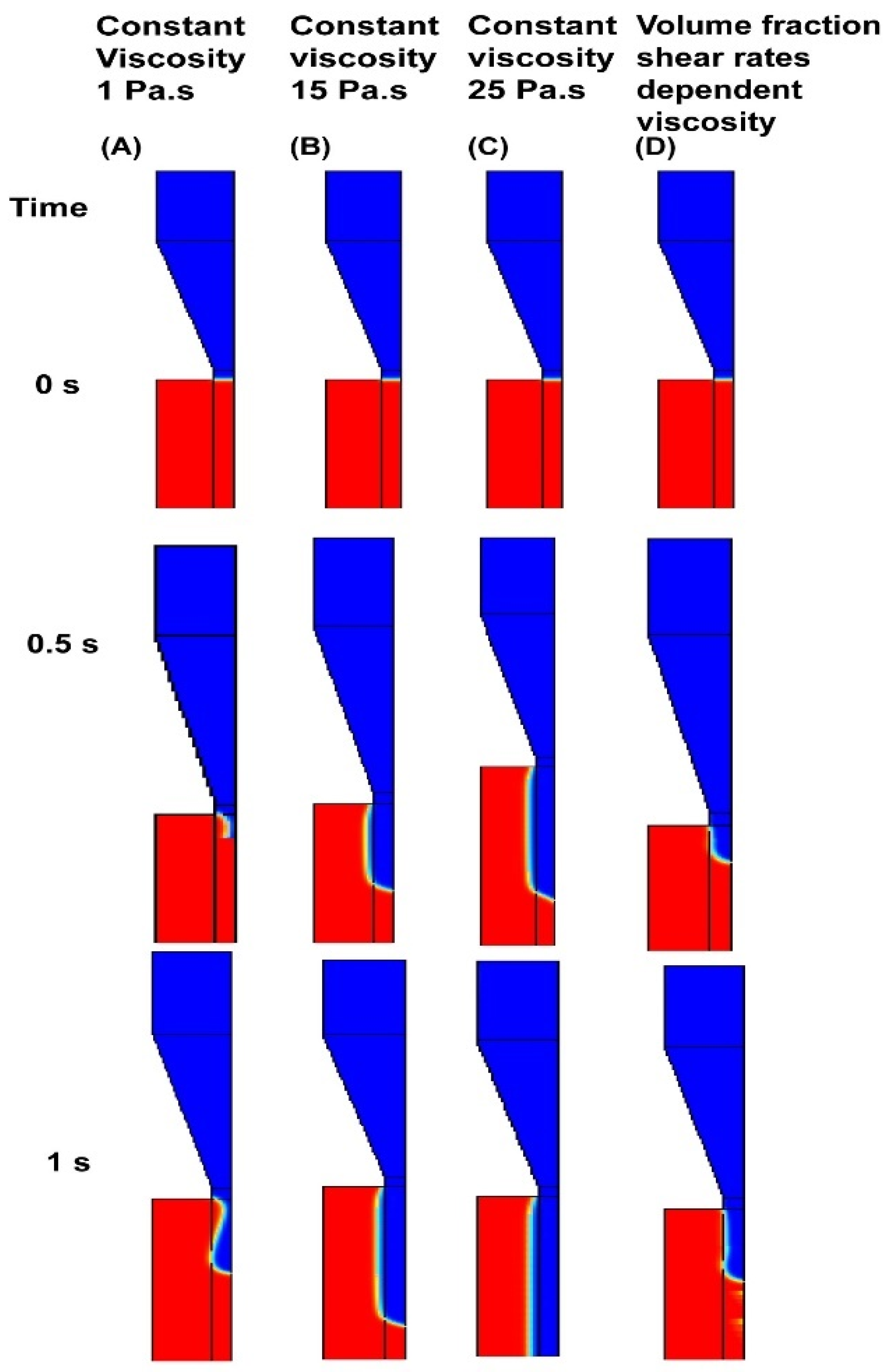
A set of numerical simulations using chitosan 3D printing was performed. First, different viscosity and velocity parameters were investigated. The major purpose was to demonstrate that any changes in the viscosity of the ink can lead to generating different shapes of fiber fluid after extruding from the nozzle. Therefore, to explore the potential effects of different variables on the fiber formation of 3D printing techniques, the viscosity of the ink was changed, whereas the velocity was kept constant. Additionally, the viscosity of the ink was regulated to constant parameters, and any potential differences in the results were observed by changing the velocity step by step. The basis is that the viscosity and velocity of the ink play a vital role in determining the shape of the extrudate ink from the nozzle. As anticipated, the results were significantly different.
As demonstrated in Figure 4, the viscosity of the ink highly affects the formation of the extruding fluid from the nozzle. Figure 4A shows what the fluid does around the nozzle; when the viscosity is low, it occurs due to the surface tension. As shown in Figure 4B,C, the fluid ink can easily flow from the nozzle and be extruded when the viscosity increases. Furthermore, the numerical simulation represents the volume fraction shear rate depending on the viscosity in the system. It is observed from this numerical simulation that increasing the viscosity and shear rate of ink influences the stable extrusion. The shape of the extrudate at higher viscosity and shear rates is bigger, as shown in Figure 4D. Hence, increasing the viscosity highly affects the instability of filaments and extrudates. A viscosity differential exists between the center and the internal wall, since high extensional stress occurs when ink is extruded from a nozzle. According to this finding, regulating the extrusion formation of chitosan ink depends on viscosity. At low viscosity, the formation of an extrusion does not happen, and the chitosan ink is around the nozzle. This trend implies that the ink cannot regularly extrude, and each layer could not support each other during the printing test.
Figure 5 shows the volume fractions and viscosities of chitosan. The extruder process was set at a time, t = 1 s. The melting point of ink viscosity was 2.0 × 10 0   kPa · s . The viscosity of air is in an extremity of a line. It can be noticed that the viscosity increases. The volume fraction is 0.5 in the boundary condition between air and ink. The dashed line indicates the theoretical boundary between the two phases in Figure 5A. Moreover, the volume fraction of the extruder printing system indicates that the interface boundary between the ink and air is wide. This wide interface of the two phases can influence simulation precision. When the interface of two flows is reduced, the simulation becomes more precise. Two options can be used to reduce the interface; 1. use finer meshes; 2. reduce the value of the parameter controlling the interfacial thickness ( ε L s ) in the level set equation. In Figure 5B, the mass fluid ink mass is demonstrated when extruder time increases. The mass of the ejected ink is approximately 3.4 × 10 9   kg . Furthermore, the mass of the ink is more than the inlet.
The formation process of the extrude ink in a 3D printing device is shown in Figure 6. The extruder ink generation is shown step by step from 1 to 7 in Figure 6. The velocity of ink was considered as 10 [m/s]. Thus, the densities of ink were set to 960.0 [ kg / m 3 ], and the dynamic viscosities of ink were equal to 25 [Pa·s]. The surface tension coefficient was 0.7 [N/m]. Furthermore, the variables used to demonstrate the velocity and viscosity were similar to those of the experimental test. Figure 6 demonstrates the velocity magnitude and volume fraction of ink in the 3D printing model. The velocity increases from inside to outside the filament formation of ink (as shown in stages 5−7), where the volume fraction and velocity of the fluid are similar to those obtained via experimental printing.
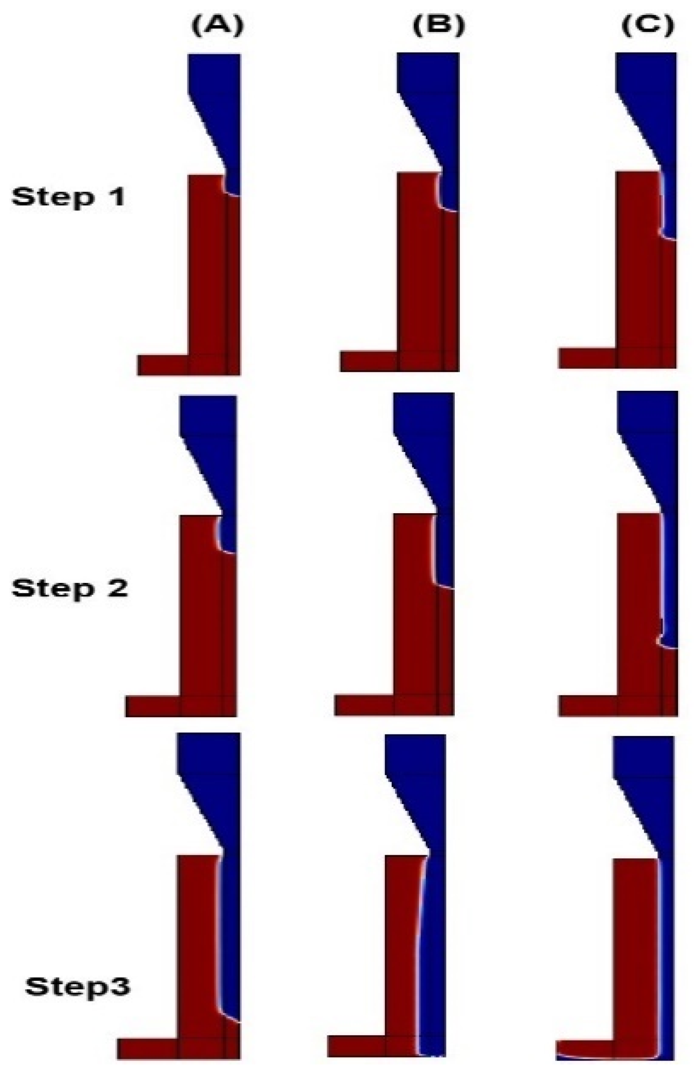
The simulation results show the filament formation and the ink extrusion shape in Figure 7 for different velocity parameters. Figure 7 presents the whole generation process, including the filament formation process of the 3D printing model. Figure 7A, step (1) presents the start of the filament formation process. At this stage, the dispersed phase (ink) completely enters the nozzle channel and begins to squeeze out of it. When the ink is squeezed out of the nozzle channel, the filament’s size increases, the ink pushes itself into the main channel, and the pressure decreases.
In the second step of the filament formation process (cf. Figure 7), the filament is elongated, and the size also increases. When the pressure reaches its maximum value, a filament is formed, and the pressure returns to a small value. Generally, surface tension and viscosity dominate the filament formation process dynamics. In Figure 7, step (3), no droplet formation occurs. However, the ink flows are in air phase distance, representing the filament formation and die swelling after extrusion from the nozzle. Figure 7 at stages 1 to 3 shows the step by step generation of the filament.
The variations in the filament length are presented in Figure 7A–C; the ink’s flow rate (velocity) is changed to another constant parameter when the filament length is short. The figures illustrate a gradual increase in the ink’s velocity rate that changes the filament’s length. The general conclusion is that the filament length increases at a corresponding scale. Furthermore, when the velocity of ink is increased from 5 [m/s] to 10 [m/s], it can be inferred from Figure 7, Step 3, that ink can easily be formed after extruding from the nozzle, showing the filament deposition shape properly.
The distance between the nozzle and filament formation is important in 3D printing. We kept this distance constant in the simulation design, as shown in Supplementary Information SI1, owing to the crosslink characteristics of novel chitosan ink. The novel chitosan inks should be printed in deionized hot water for better crosslink. However, the preparation of this environment in COMSOL Multiphysics is not feasible. Therefore, the distance between the nozzle and filament formation was 2 cm.
The formation of hydrogel extrusion in the 3D printing technique is presented. Simulations were conducted using the two-phase level set method; the ink flow from the nozzle was regulated by controlling the velocity during simulation. Thus, the velocity magnitude of the numerical simulations is demonstrated in Figure 8. The findings revealed that the size of the filaments was determined based on counting the pixels using the COMSOL software (Hangzhou, China). Figure 8 presents the surface of the velocity magnitude. The effect of the velocity on the shape of the extruded is determined from 0 m/s to 1.6 m/s. The observations showed that the extruded shape was cylindrical with a smooth surface for the lowest shear rates. In contrast, deformations were observed on the surface at higher shear rates and inlet velocities. These numerical simulation results reveal that when the inlet velocity increases, the ink flow stabilizes with no deformation of the extrudate. Therefore, the numerical simulation precisely reacts to the filament formation after extrusion from the nozzle. By comparing the filament formation of the numerical simulation and experimental test, it can be inferred that the shape of the filament in the numerical simulation has proper stability.
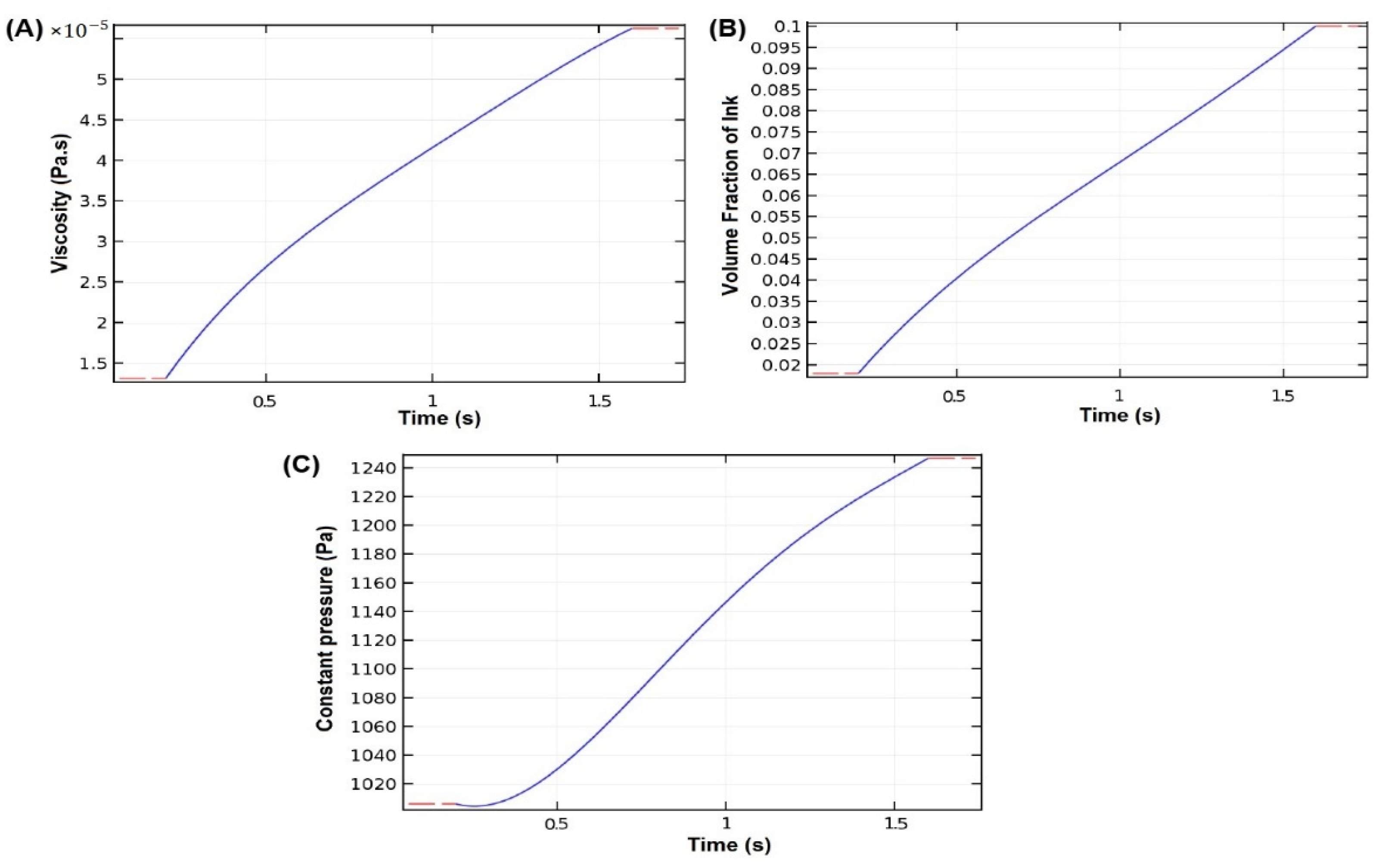
The abovementioned findings with the information presented in Figure 9A show that the volume fractions will scale the relationship between the viscosity and the volume fractions as a function of time. The results of viscosity were compared. As expected, it is inferred that the plot of the viscosity increases, and thus, the volume fraction of ink can have a more dramatic increase. Hence, in Figure 9B, the volume fraction is increased from 0.02 to 0.1. The constant pressure becomes highly dependent on the ink flow rate at the increased viscosity and volume fraction, as shown in Figure 9C. Therefore, it resulted in the numerical simulation of the obvious viscosity and velocity formation of chitosan ink, where the extruded phase starts.

4.2. Model Validation–Printed Chitosan Hydrogel

4.2.1. Preparation Material for Experimental Test

The chitosan aqueous solution was prepared by dissolving chitosan in an alkaline solvent. The chitosan powder with a level of deacetylation (DD = 89%) sourced from Ruji Biotechnology Co., Ltd. (Hangzhou, China). was used. Firstly, LiOH, urea, KOH, and deionized water with a mass ratio of 4.5:8:7:80.5 were mixed to prepare an alkaline aqueous solvent. All the chemicals were purchased from Sigma–Aldrich. The chitosan powder (4 wt%) was dissolved in an alkaline solution. The solution was stirred for 5 min at room temperature. It was then stored at −30 °C for 6 h until completely frozen. Afterwards, the solid solution was thawed and stirred at room temperature. After centrifugation (7000 rpm, 10 min under 5 °C) to eliminate air bubbles, the chitosan hydrogel was ready, with a concentration of 4 wt%. All the solutions were freshly prepared before using the 3D printing experiment. The chitosan 3D printing system is shown in Figure 10. The experimental system uses a 3D printer, EFL-BP-6800, from Suzhou Intelligent Manufacturing Research Institute. A nozzle temperature controller and a plate temperature controller are equipped to control the temperature during printing.

4.2.2. Chitosan 3D Printing Method

This technique uses chitosan-based ink to be loaded in a syringe and assembled into a printer with a nozzle shield. The temperature controller was designed around the syringe to avoid chitosan pre-gel solution gel formation during printing. Chitosan ink must be stored at low temperatures because of the complex formation of its hydrogen bond. Moreover, the chitosan ink was extruded into hot deionized water. The heating system was implemented under a receiving plate to maintain the stable temperature of deionized water for better situ-crosslink. This process makes rapid situ-crosslink, which leads to self-support and adhesion of the filament layer. The printing chitosan shape was created. After printing, the sample was immersed in a hot water bath for 30 min at a temperature of 60 °C. Subsequently, the form of chitosan physical hydrogel was obtained. The printing procedure, including the hardware and software systems, is reported in Supplementary Information SI.

4.2.3. Printability Results of Chitosan Hydrogel

The relevant chitosan biomaterials were extruded by air in their positions in this study’s direct writing (DIW) technique. The corresponding nozzle adjusted the air pressure. When chitosan-based ink was extruded from the nozzle to the substrate, the nozzle moved horizontally, and the chitosan based-ink was embedded in the form of fiber in the relevant layer position. These fibers were parallel to each other. The distance between each fiber depends on the user-defined porosity during the design phase. After completing one layer, the nozzle rotates 90 degrees and prints the next layer. This process continued until a complete physical chitosan structure was obtained, as shown in Figure 10A. Various factors can impact the printing of chitosan hydrogel with high resolution. An experimental test was conducted to examine the printing settings; the nozzle diameter, air pressure, and printing speed are all printing settings. Figure 10B shows the nozzle diameter D, where an air pressure P extruded chitosan hydrogel ink. The printer nozzle moves at V speed to make chitosan fiber. Microscope multifunction determined the fiber diameter, as shown in Figure 10C. Figure 10D shows that the printing setting proficiently regulates the diameter of the printed chitosan fiber. The effect of the nozzle diameter is obvious in 3D printing. More accurately, a larger nozzle diameter, D, has a larger printed fiber diameter. In addition, the diameter of the extruded fiber is typically larger than the nozzle diameter, owing to the effect of die-swelling viscoelastic ink. Therefore, the results reveal that the fiber diameter D will be larger when the velocity V increases. This finding reveals the same phenomena in a simulation study. In CFD simulation with increasing velocity, the fiber diameter will be large, as shown in Figure 7. Thus, the simulation and 3D printing tests have shown the same results. Due to the traction effect of the printed fiber, the fiber diameter D decreases when the printing speed V is increased. As illustrated in Figure 10E, the fiber diameter will be larger when the concentration viscosity of chitosan ink decreases, owing to the effect of the chitosan chain in die-swelling. These findings certify the simulation study, which reveals similar phenomena in an experimental test. Additionally, a simulation study showed that when the viscosity is low, the extrusion nozzle does not occur, and the chitosan ink develops around the nozzle; however, increasing the viscosity to 25 Pa·s causes the extrusion formation to occur. In the experimental test, when the concentration of chitosan ink was 3.5 wt%, the printed structure was too weak to support each layer. Although at 4 wt% concentration, chitosan printing was fidelity; a high concentration of chitosan ink results in the clogging of the nozzle. Therefore, we preferred a 4 wt% concentration of chitosan ink for the printing sample.
3D printing of different three-dimensional models was performed to demonstrate the quality of the printed chitosan hydrogel. Hydrogel scaffold can be printed with high resolution and quality, as shown in Figure 4A,B. These models were selected to evaluate the effect of the simulation and the height of the infill level. More specifically, it notes that the important parameters of the experimental test were used according to the simulation result. Simulation and printing tests employed the viscosity and density parameters in the Supplementary SI. The print speed was set at 50 mm/s, the outer perimeter speed was 45 mm/s, and the infill speed was set at 80 mm/s. The dimensions of a printed scaffold are 5 × 5 mm, and the scale bar of an optical image of a printed scaffold is 2 mm. The experimental and numerical results indicate that the three-dimensional structure was printed with the appropriate resolution. As shown in Figure 10F, the scaffold specimen was printed with high quality.

5. Conclusions

A combined experimental and numerical study was performed to evaluate the printing of the chitosan hydrogel, which included numerical simulations of extrusion-based chitosan 3D printing devices. According to the simulations, the two phases comprised a nozzle through which the inner fluid, or dispersive phase (chitosan ink), entered through a vertical channel, and a continuous phase or air impinged on the dispersive phase from side channels in a diametrical contact with each other. Additionally, the filament size and extrusion ink from the nozzle can accelerate the extrusion formation depending on the velocity and viscosity ratios of the two-phase flow rate ratios of the incoming ink fluids. The length of the filament also increases with an increase in velocity as well as an increasing viscosity rate. Therefore, it can be inferred from the results of the 3D printing device that the extrude breakup time from a nozzle (period of extruding formation) decreased as the volume fraction increased. This trend occurs primarily due to the shearing force, which causes the formation of the extrusion ink between the continuous phase (air) and discrete phase (hydrogel ink), and can also be observed from the simulations. Furthermore, an actual 3D printing experiment was employed in the validation model of chitosan hydrogel printing. The effect of different printing parameters was studied to evaluate the printing process. The simulation and experimental evaluation results can help reduce the cost and time of the printing process of chitosan hydrogel. Therefore, this study will be significant in constructing chitosan hydrogels in tissue engineering applications.

Supplementary Materials

The following supporting information can be downloaded at: https://www.mdpi.com/article/10.3390/app12157530/s1. Supporting Information is available from the Applied Science Library or from the author. The schematic of the two-dimensional simulation (COMSOL 5.2a) for the extrusion-based 3D printing method will be given. The dimension of the main channel is 15   mm in height, and in width 2   mm , and the side channel is 0.4   mm in width. Further, the parameters are given. Where the density of ink is set as 1 × 10 3   kg / m 3 and 0.02 × 10 3   kg / m 3 and the density of air is 1.225 × 10   3   kg / m 3 . And the viscosity of ink is 150 × 10 1   Pa · s to 250 × 10 1   Pa · s and viscosity of air is   1.789 × 10 5   Pa · s , the surface tension coefficient is 0.07   N / m . Furthermore, the ink velocity was adjusted to 1 [m/s], 2 [m/s], 3 [m/s]. For this numerical simulation, physics-controlled meshes use the predefined finer size and free triangular.

Author Contributions

Formal analysis, S.M.M. and H.R.; Supervision, Y.H.; Writing—original draft, Y.H. and H.R.; Writing—review & editing, S.M.M. All authors have read and agreed to the published version of the manuscript.

Funding

This work was sponsored by the National Key Research and Development program of China (2018YFA0703000), the science Fund for Creative Research Groups of the National Natural Science Foundation of China (no. 51521064).

Institutional Review Board Statement

Not applicable.

Informed Consent Statement

Not applicable.

Data Availability Statement

Supporting Information is available from the Applied Science library as below link; https://www.mdpi.com/ethics.

Conflicts of Interest

The authors declare no conflict of interest.

References

  1. Guvendiren, M.; Molde, J.; Soares, R.M.D.; Kohn, J. Designing Biomaterials for 3D Printing. ACS Biomater. Sci. Eng. 2016, 2, 1679–1693. [Google Scholar] [CrossRef] [PubMed]
  2. Li, J.; Wu, C.; Chu, P.K.; Gelinsky, M. 3D printing of hydrogels: Rational design strategies and emerging biomedical applications. Mater. Sci. Eng. R Rep. 2020, 140, 100543. [Google Scholar] [CrossRef]
  3. Zhang, X.N.; Zheng, Q.; Wu, Z.L. Recent advances in 3D printing of tough hydrogels: A review. Compos. Part B Eng. 2022, 238, 109895. [Google Scholar] [CrossRef]
  4. Tool, S.M. 3D Printing of a Reactive Hydrogel Bio-Ink Using a Static Mixing Tool. Polymers 2020, 12, 1986. [Google Scholar] [CrossRef]
  5. Diego, S. Recent advances in extrusion-based 3D printing for biomedical applications. Adv. Healthc. Mater. 2019, 7, 1701161. [Google Scholar] [CrossRef]
  6. Jiménez, M.; Romero, L.; Domínguez, I.A.; Espinosa, M.D.M.; Domínguez, M. Additive Manufacturing Technologies: An Overview about 3D Printing Methods and Future Prospects. Complexity 2019, 2019, 9656938. [Google Scholar] [CrossRef] [Green Version]
  7. Do, A.-V.; Smith, R.; Acri, T.M.; Geary, S.M.; Salem, A.K. 3D Printing Technologies for 3D Scaffold Engineering; Materials, Technologies and Applications; Elsevier Ltd.: Singapore, 2018; ISBN 9780081009796. [Google Scholar]
  8. Jang, T.-S.; Jung, H.-D.; Pan, H.M.; Han, W.T.; Chen, S.; Song, J. 3D printing of hydrogel composite systems: Recent advances in technology for tissue engineering. Int. J. Bioprint. 2018, 4, 126. [Google Scholar] [CrossRef]
  9. Choi, Y.; Kim, C.; Kim, H.S.; Moon, C.; Lee, K.Y. 3D Printing of dynamic tissue scaffold by combining self-healing hydrogel and self-healing ferrogel. Colloids Surf. B Biointerfaces 2021, 208, 112108. [Google Scholar] [CrossRef]
  10. Ahmed, S.; Ikram, S. Chitosan Based Scaffolds and Their Applications in Wound Healing. ALS 2016, 10, 27–37. [Google Scholar] [CrossRef] [Green Version]
  11. Wong, J.Y. Ultra-Portable Solar-Powered 3D Printers for Onsite Manufacturing of Medical Resources. Aerosp. Med. Hum. Perform. 2015, 86, 830–834. [Google Scholar] [CrossRef]
  12. Derakhshanfar, S.; Mbeleck, R.; Xu, K.; Zhang, X.; Zhong, W.; Xing, M. 3D bioprinting for biomedical devices and tissue engineering: A review of recent trends and advances. Bioact. Mater. 2018, 3, 144–156. [Google Scholar] [CrossRef] [PubMed]
  13. Liu, C.; Xu, N.; Zong, Q.; Yu, J.; Zhang, P. Hydrogel prepared by 3D printing technology and its applications in the medical field. Colloids Interface Sci. Commun. 2021, 44, 100498. [Google Scholar] [CrossRef]
  14. Michailidou, G.; Koukaras, E.N.; Bikiaris, D.N. Vanillin chitosan miscible hydrogel blends and their prospects for 3D printing biomedical applications. Int. J. Biol. Macromol. 2021, 192, 1266–1275. [Google Scholar] [CrossRef]
  15. Calvert, P. Hydrogels for soft machines. Adv. Mater. 2009, 21, 743–756. [Google Scholar] [CrossRef]
  16. Yoshikawa, M.; Sato, R.; Higashihara, T.; Ogasawara, T.; Kawashima, N. Rehand: Realistic electric prosthetic hand created with a 3D printer. In Proceedings of the 2015 37th Annual International Conference of the IEEE Engineering in Medicine and Biology Society (EMBC), Milan, Italy, 25–29 August 2015; pp. 2470–2473. [Google Scholar]
  17. Das, S.; Basu, B. An Overview of Hydrogel-Based Bioinks for 3D Bioprinting of Soft Tissues. J. Indian Inst. Sci. 2019, 99, 405–428. [Google Scholar] [CrossRef]
  18. Topuz, M.; Dikici, B.; Gavgali, M.; Yilmazer, H. A Review on the Hydrogels Used in 3D Bio-Printing. Int. J. 3D Print. Technol. Digit. Ind. 2018, 2, 68–75. [Google Scholar]
  19. Kyle, S.; Jessop, Z.M.; Al-Sabah, A.; Whitaker, I.S. Printability of Candidate Biomaterials for Extrusion Based 3D Printing: State-of-the-Art. Adv. Healthc. Mater. 2017, 6, 1700264. [Google Scholar] [CrossRef]
  20. Townsend, J.M.; Beck, E.C.; Gehrke, S.H.; Berkland, C.J.; Detamore, M.S. Flow behavior prior to crosslinking: The need for precursor rheology for placement of hydrogels in medical applications and for 3D bioprinting. Prog. Polym. Sci. 2019, 91, 126–140. [Google Scholar] [CrossRef]
  21. Li, H.; Tan, C.; Li, L. Review of 3D printable hydrogels and constructs. Mater. Des. 2018, 159, 20–38. [Google Scholar] [CrossRef]
  22. Murphy, S.V.; Atala, A. 3D bioprinting of tissues and organs. Nat. Biotechnol. 2014, 32, 773–785. [Google Scholar] [CrossRef] [PubMed]
  23. He, Y.; Yang, F.; Zhao, H.; Gao, Q.; Xia, B.; Fu, J. Research on the printability of hydrogels in 3D bioprinting. Sci. Rep. 2016, 6, 29977. [Google Scholar] [CrossRef] [PubMed]
  24. Zolfagharian, A.; Kaynak, A.; Khoo, S.Y.; Kouzani, A.Z. Polyelectrolyte Soft Actuators: 3D Printed Chitosan and Cast Gelatin. 3d Print. Addit. Manuf. 2018, 5, 138–150. [Google Scholar] [CrossRef]
  25. Rinaudo, M. Chitin and chitosan: Properties and applications. Prog. Polym. Sci. 2006, 31, 603–632. [Google Scholar] [CrossRef]
  26. Croisier, F.; Jérôme, C. Chitosan-based biomaterials for tissue engineering. Eur. Polym. J. 2013, 49, 780–792. [Google Scholar] [CrossRef] [Green Version]
  27. Giorleo, L.; Tegazzini, F.; Sartore, L. 3D printing of gelatin/chitosan biodegradable hybrid hydrogel: Critical issues due to the crosslinking reaction, degradation phenomena and process parameters. Bioprinting 2021, 24, e00170. [Google Scholar] [CrossRef]
  28. Yan, Q.; Dong, H.; Su, J.; Han, J.; Song, B.; Wei, Q.; Shi, Y. A Review of 3D Printing Technology for Medical Applications. Engineering 2018, 4, 729–742. [Google Scholar] [CrossRef]
  29. Dash, M.; Chiellini, F.; Ottenbrite, R.M.; Chiellini, E. Chitosan—A versatile semi-synthetic polymer in biomedical applications. Prog. Polym. Sci. 2011, 36, 981–1014. [Google Scholar] [CrossRef]
  30. Chang, C.; Zhang, L. Cellulose-based hydrogels: Present status and application prospects. Carbohydr. Polym. 2011, 84, 40–53. [Google Scholar] [CrossRef]
  31. Wei, Z.; Yang, J.H.; Liu, Z.Q.; Xu, F.; Zhou, J.X.; Zrínyi, M.; Osada, Y.; Chen, Y.M. Novel biocompatible polysaccharide-based self-healing hydrogel. Adv. Funct. Mater. 2015, 25, 1352–1359. [Google Scholar] [CrossRef]
  32. Zhou, L.; Ramezani, H.; Sun, M.; Xie, M.; Nie, J.; Lv, S.; Cai, J.; Fu, J.; He, Y. 3D printing of high-strength chitosan hydrogel scaffolds without any organic solvents. Biomater. Sci. 2020, 8, 5020–5028. [Google Scholar] [CrossRef]
  33. Wu, Q.; Therriault, D.; Heuzey, M.C. Processing and Properties of Chitosan Inks for 3D Printing of Hydrogel Microstructures. ACS Biomater. Sci. Eng. 2018, 4, 2643–2652. [Google Scholar] [CrossRef] [PubMed]
  34. Rajabi, M.; McConnell, M.; Cabral, J.; Ali, M.A. Chitosan hydrogels in 3D printing for biomedical applications. Carbohydr. Polym. 2021, 260, 117768. [Google Scholar] [CrossRef] [PubMed]
  35. Zhao, C.Q.; Liu, W.G.; Xu, Z.Y.; Li, J.G.; Huang, T.T.; Lu, Y.J.; Huang, H.G.; Lin, J.X. Chitosan ducts fabricated by extrusion-based 3D printing for soft-tissue engineering. Carbohydr. Polym. 2020, 236, 116058. [Google Scholar] [CrossRef]
  36. Chiesa, I.; Ligorio, C.; Bonatti, A.F.; De Acutis, A.; Smith, A.M.; Saiani, A.; Vozzi, G.; De Maria, C. Modeling the Three-Dimensional Bioprinting Process of β-Sheet Self-Assembling Peptide Hydrogel Scaffolds. Front. Med. Technol. 2020, 2, 571626. [Google Scholar] [CrossRef]
  37. Göhl, J.; Markstedt, K.; Mark, A.; Håkansson, K.; Gatenholm, P. Simulations of 3D bioprinting: Predicting bioprintability of nanofibrillar inks. Biofabrication 2018, 10, 1758–5090. [Google Scholar] [CrossRef] [PubMed]
  38. Guo, C.; Zhang, M.; Bhandari, B. A comparative study between syringe-based and screw-based 3D food printers by computational simulation. Comput. Electron. Agric. 2019, 162, 397–404. [Google Scholar] [CrossRef]
  39. Zhu, Y.; Song, K.; Jiang, S.; Chen, J.; Tang, L.; Li, S. Numerical Simulation of Mass Transfer and Three-Dimensional Fabrication of Tissue-Engineered Cartilages Based on Chitosan / Gelatin Hybrid Hydrogel Scaffold in a Rotating Bioreactor. Appl. Biochem. Biotechnol. 2017, 181, 250–266. [Google Scholar] [CrossRef]
  40. Behdani, B.; Senter, M.; Mason, L.; Leu, M.; Park, J. Numerical Study on the Temperature-Dependent Viscosity Effect on the Strand Shape in Extrusion-Based Additive Manufacturing. J. Manuf. Mater. Process. 2020, 4, 46. [Google Scholar] [CrossRef]
  41. Wu, Q.; Maire, M.; Lerouge, S.; Therriault, D.; Heuzey, M.-C. 3D Printing of Microstructured and Stretchable Chitosan Hydrogel for Guided Cell Growth. Adv. Biosyst. 2017, 1, 1700058. [Google Scholar] [CrossRef]
  42. Duan, J.; Liang, X.; Cao, Y.; Wang, S.; Zhang, L. High strength chitosan hydrogels with biocompatibility via new avenue based on constructing nanofibrous architecture. Macromolecules 2015, 48, 2706–2714. [Google Scholar] [CrossRef]
  43. Hon, K.K.B.; Li, L.; Hutchings, I.M. Direct writing technology-Advances and developments. CIRP Ann. Manuf. Technol. 2008, 57, 601–620. [Google Scholar] [CrossRef]
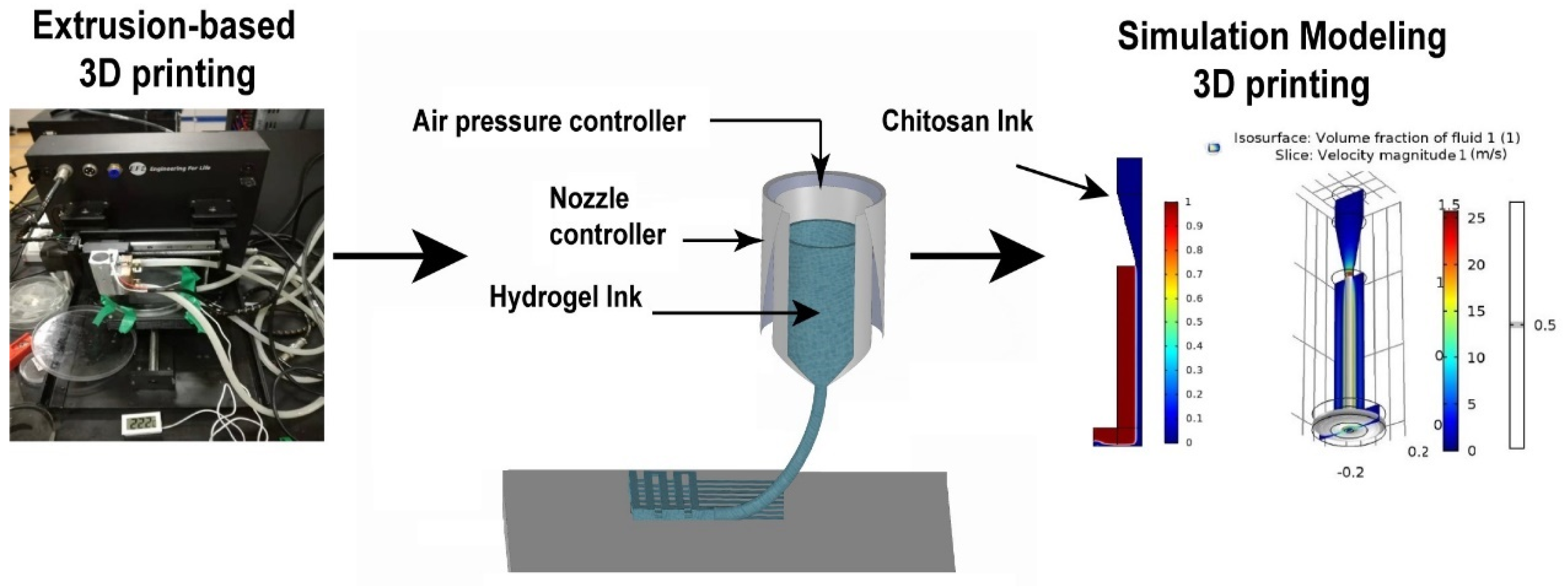
Figure 1. Schematic description of the numerical simulation of hydrogel 3D printing.
Applsci 12 07530 g001
Figure 2. Presentation of different phases in the two-phase flow simulation by a level set method.
Applsci 12 07530 g002
Figure 3. Schematic boundary condition representation for the numerical simulation of chitosan 3D printing.
Applsci 12 07530 g003
Figure 4. Influence of the viscosity on the behavior of the extruding hydrogel ink; (A) Constant viscosity = 1 Pa·s; (B) Constant viscosity 15 Pa·s; (C) Constant viscosity = 25 Pa·s; (D) Shear rate-dependent viscosity.
Applsci 12 07530 g004
Figure 5. (A) Illustrated is the volume fraction and viscosity during chitosan 3D printing; (B) description of the mass fluid ink during simulation of chitosan 3D printing.
Applsci 12 07530 g005
Figure 6. Filament formation in extrusion chitosan 3D printing device with the COMSOL software.
Applsci 12 07530 g006
Figure 7. The extrusion formation process in extrusion 3D printing, when the velocity increases; showing process (A) squeezing, (B) dripping, and (C) fluid flow.
Applsci 12 07530 g007
Figure 8. Effect of inlet velocity and shear rate on chitosan extrusion 3D printing.
Applsci 12 07530 g008
Figure 9. (A) Viscosity of ink; (B) volume Fraction of ink; and (C) constant pressure of 3D printing.
Applsci 12 07530 g009
Figure 10. (A) Schematic illustration of chitosan hydrogel. (B) Typical setup for printing chitosan hydrogels. (C) Schematic of measuring fiber diameters. (D) Effect of the velocity on the printed fiber diameter. (E) Effect of the viscosity v on the fiber diameter d. (F) Optical image of a printed scaffold Scale bar: 2 mm.
Applsci 12 07530 g010
Publisher’s Note: MDPI stays neutral with regard to jurisdictional claims in published maps and institutional affiliations.