Abstract
This article considers external loads experienced on the rotor actuator of the universal continuous earthmoving machinery when digging wide excavations (ditches) in the soil and the ways to improve its productivity. Under the condition of translational and rotational supply of the soil-developing actuator to the face, the possibility of minimizing and leveling external loads on the actuator by improving the kinematics of its cyclic movement in the face has been experimentally proved. The actuator should move according to the required trajectory, which corresponds to the curve of the lemniscate of Bernoulli. The load of the UEM soil-developing actuator, operating in the mode of digging the soil, and the effectiveness of the suggested method for leveling the external loads have been experimentally assessed on the current physical model of the operating equipment. Leveling and reducing the absolute values of loads on the UEM operating equipment is achieved by improving the actuator trajectory optimization when digging the soil. It implies the additional rotation of the actuator intermediate frame at the end of each half cycle of the operating process. The required duration of the additional rotation of the intermediate frame is functionally dependent on the actual speed of machinery movement. The additional rotation of the intermediate frame, the duration of which is 1.1 s in the mode of maximum productivity, reduces the maximum load of the operating equipment, namely: torque on the rotor axis Mt-by 19% (up to 60 kN m), the components of the main force vector: vertical force-by 9% (up to 40 kN), and lateral force Pl.m-by 32% (up to 58 kN). The obtained results enable to comprehensively assess the maximum load of the UEM operating equipment under the conditions of changing values of the factors on which it depends and to objectively assess the directional stability of the machinery. Aligning the thickness of the shavings cut by the buckets of the rotor actuator in a half-cycle enables to improve the productivity of the universal earthmoving machinery almost twice.
Keywords:
transport; algorithm; vehicle; machinery; actuator; motion trajectory; symmetrical grooves 1. Problem Formulation
Earthworksth are one of the most important stages of any transport construction project. The overall cost of earthmoving activity during construction projects can account for more than 30% of the total cost [1]. The construction of pipe communications for various purposes, communication lines, irrigation canals, and other similar facilities, first of all, requires fast and high-quality earthworks with minimal financial costs [2]. One scientific article [3] described the energy intensity of the soil digging process and the nature of changes in the values that make up the cutting forces acting on the actuator, which are necessary for effective interaction with soil.
Earthworks can be done in the shortest possible time by using continuous earthmoving machinery able to provide earthworks with a productivity of 5–10 times higher than the operation of single-bucket excavators. However, continuous excavators are ad hoc machinery and can construct only long excavations in the ground of specified dimensions, which limits the scope of their use. Recently, there has been an acute necessity to increase the pace of earthworks in transport construction. As a result, the researchers’ efforts in the field of excavation engineering are increasingly aimed at creating the universal continuous earthmoving machinery (UEM) able to dig long excavations of variable width and depth [4] with the same actuator without realignment of machinery equipment. Technological capabilities of the machinery are expanded by combining the variations of three speeds that move the soil-developing actuator in the face, namely: cutting the soil with the rotor revolution speed Vc, supplying the actuator to the face due to translational movement of the machinery with the speed Vs, and cyclic lateral reciprocating movement of the actuator relative to the longitudinal axis of the machinery at a certain angle α with a speed Vl.m, see Figure 1.
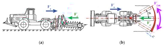
Figure 1.
UEM with a single swivel (uniaxial) mounting of the actuator: (a) side view; (b) the scheme of developing a wide excavation (pit).
The combination of translational movement of the machinery with simultaneous lateral reciprocating movement of the soil-developing actuator characterizes the mode of translational and rotational supply of the actuator to the face. The peculiarity of such movement of the UEM actuator in the face is its cyclicity. The full cycle of movement is carried out when the actuator moves from one extreme point (the side wall of the excavation in the soil) to the second one and vice versa, to the starting point. The actuator movement from one side wall of the excavation in the soil to another (opposite) one is a half-cycle of movement (Figure 1).
When digging excavations of the minimum width (trench), the actuator remains stationary relative to the longitudinal axis of the machinery, and the width of the excavation is determined by the width of the actuator.
The PZM-2 machinery with a chain actuator and its modification PZM-3 are widely known continuous UEM with the specified mounting [5,6].
If the above-mentioned structural scheme of the mounting (Figure 1) of soil-developing equipment on the base chassis is used, in the mode of translational and rotational supply of the actuator to the face, the excavation is determined by the speed ratio Vs and Vl.m and is developed by uneven wedge-shaped shavings. Their thickness c varies from zero to a definite maximum for each half cycle of movement. It causes fluctuations in the value of external loads on the actuator when digging the soil and reduces the reliability and durability of the machinery. In addition, the potential productivity of the rotor actuator in this case is 50%.
The analysis of the UEM operating processes shows that the reduction, stabilization, and minimization of external loads of the UEM actuator, the machinery productivity improvement can be achieved by aligning the thickness of the shavings cut by the actuator buckets during each half-cycle of the actuator motion in the face.
The aim of the study is to suggest and experimentally substantiate a method for leveling and minimizing external loads on the continuous UEM rotor actuator when digging excavations of different widths without readjustment of the actuator by improving the kinematics of its movement in the face with a simultaneous increase in the machinery productivity.
2. The Analysis of Research Results and Publications
The reduction and stabilization of external loads acting on the soil-developing actuators of continuous earthmoving machinery [7,8,9], as well as improving the machinery productivity, are not new issues. They were raised and addressed as a result of numerous studies [10,11] of the known designs of the machinery.
The peculiarity of this study is the characteristics of the soil-developing actuator movement in the face, namely moving in the mode of translational and rotational supply of the actuator when digging the soil. There is a mechanical method for providing such a supply [12]. A hydrostatic method for ensuring the movement of the operating equipment in the process of digging the soil is objectively considered to be more progressive [13]. More often, the issue of minimization and stabilization of external loads was raised in relation to quarry continuous rotor excavators, where the fluctuations in the value of external loads could cause significant stresses in the metal structures of booms and drives of the operating equipment, and could even lead to its destruction [14,15]. Fluctuations in the value of external loads over time on the actuators of earthmoving machinery, as well as their value, are determined by the invariability and stability of geometric parameters of the shavings cut by the actuator buckets or scrapers during digging, especially shaving thickness. The studies of the Anhui University of Technology (China) [16] are known to have solved the problem of reducing the specific energy consumption for cutting and response to load changes when driving a continuous multi-purpose machinery for developing coal and rocks by optimizing the speed of rock cutting and the actuator supply. However, the process of speed regulation depending on changes in the physical and mechanical characteristics of the rock being developed is quite complex and energy-intensive. This is not the best solution of the problem determined in the aim of the study. Multi-parameter control of the cutting actuator of the multi-purpose machinery [17] is also quite difficult and expensive to provide, despite the fact that it enables to improve productivity.
There is a system of adaptive control of the rock cutter movement in the horizontal plane by selecting and adjusting the cutting speed depending on the rock properties [18]. This ensures the adaptation of the machinery actuators to the characteristics of the environment being developed and improves the efficiency and productivity of the machinery.
The results of theoretical studies on determining the influence of specific factors on productivity of bucketless chain trench machinery are known. These factors include trench depth and width, soil cutting angle (by soil cutters), distances between cutters fixed on a bucket or a beam, tangential speed of teeth (cutting speed), and supply speed (movement) of the machinery [19]. However, the algorithm for complex selection of optimal values of these factors characteristics for specific actuators has not been developed.
Automation of operating processes of trench machinery has been suggested [20] in the literature, but this solves the problem only partially.
Ref. [16] considered the issue of adaptive control of the rotor actuator cutting speed of a cutter-loader with a rotor actuator depending on its load. The problems of the shaving thickness alignment were not considered in the paper.
Ref. [19] studied the factors affecting the productivity of a chain trencher: digging depth; trench width and actuator angle; structural parameters of the actuator chain; cutting speed and the machinery movement speed. Special attention is paid to the theoretical study of factors affecting the movement speed of the chain trencher, the relationship between the productivity of the chain actuator in terms of carrying capacity and the productivity of the machinery in order to avoid soil extrusion. Although the excavator actuator is similar to the one discussed in [5] and presented in Figure 2, the lateral movement of the actuator was not considered. There are no materials regarding the shaving alignment and the actuator load leveling during the operating cycle.
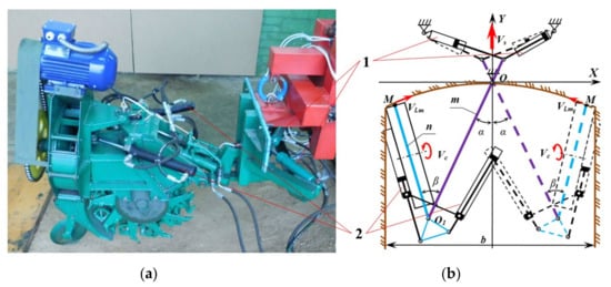
Figure 2.
A structural diagram of the double swivel, two-link mounting of the actuator on the base chassis: (a) design implementation on the physical model; (b) diagram: 1–hydraulic cylinders of lateral movement of the intermediate frame; 2–hydraulic cylinders of lateral movement of a rotor frame (Vs—machinery supply speed; Vc—soil cutting speed; Vl.m—lateral supply speed; b—trench width; α—rotation angle of the intermediate frame (±15°); β—rotation angle of the rotor frame (±45°); m—intermediate frame; n—the actuator frame).
Ref. [21] suggested an approach based on determining the forces affecting the bucket of a hydraulic excavator during soil development. Its implementation provides real-time force estimation, which is a necessary prerequisite for solving the problem of creating unmanned earthmoving machinery. The issues of load leveling during the operation of trench excavators were not considered.
Ref. [22] is devoted to determining the values and patterns of the distribution of operating loads acting on a bucket excavator, which can lead to a loss of machinery stability. Limiting conditions for the loss of stability were determined using numerical modeling and experimental testing. The loss of stability of multi-bucket excavators and the influence of kinematic and power parameters of the rotor actuator on it were not considered.
3. Statement of Basic Materials
When carrying out previous research, it was established that soil development by the UEM with shavings of uniform thickness can be done by providing additional movement of the actuator relative to the stern of the base chassis in the direction of the machinery movement and by controlling the formation of soil shavings with lateral movement of the actuator [23,24].
Digging the soil with shavings of uniform thickness, with the additional supply of the actuator in the direction of the machinery movement near lateral walls of the excavation, can be carried out by a method developed with our participation using double swivel, two-link mounting of the soil-developing operating equipment on the base chassis. A structural diagram of the mounting design is shown in Figure 2.
In accordance with the developed technical design proposal of the double swivel, two-link mounting of the operating equipment, lateral movement in the face with the speed Vl.m is provided by simultaneous rotation of pairs of individual hydraulic cylinders, two links of the mounting (m-intermediate frame and n-the actuator frame) relative to their swivels O and O1 (Figure 2). The developed soil is moved by the rotor buckets from the face to the thrower, which transports it for laying into a parapet. At a certain rotational speed, under the influence of centrifugal forces on the ground, the rotor buckets are unloaded.
The movement of the actuator from one wall of the excavation to another one is a half-cycle thc of the operating process.
The rotation of the intermediate frame in the face for the half-cycle is provided by hydraulic cylinders 1 (Figure 2), with which the link is deflected by an angle 2α. At the same time, the frame of the actuator by means of the second pair of hydraulic cylinders 2 rotates at an angle 2β around the swivel O1 located on the intermediate frame.
The half-cycle of lateral movement of the actuator in the face thc is characterized by two stages. In the first stage with the duration t2, both lateral movement mechanisms operate simultaneously: the intermediate frame rotates relative to the swivel O at the stern of the base chassis, and the actuator frame rotates relative to the swivel O1 on the intermediate frame. In the second stage of the half-cycle, the movement of the rotor frame relative to the intermediate frame is blocked. The time during which further angular movement of the intermediate frame relative to the stern of the machinery occurs after stopping the rotor frame rotation is the delay time in rotation of this frame tar (the time of additional rotation of the intermediate frame).
Thus, the total duration of the actuator movement in the face for a half-cycle when digging the soil includes the duration of simultaneous rotation relative to the corresponding swivels of both mounting frames plus the duration of additional rotation at the end of the half-cycle of the intermediate frame.
A wide excavation with shavings of uniform thickness by the two-link actuator can be developed, provided that the linear motion of the machinery and constant parameters of the excavation width b = const and depth h = const are maintained, the kinematic characteristics of the operating process for a half-cycle will be unchanged, i.e., . The operating characteristics will change only when the operating modes are changed.
In this case, to ensure the development of soil with shavings of constant thickness, the duration of additional rotation of the intermediate frame should be variable and should be determined by the speed of longitudinal movement of the machinery . The higher the speed of the machinery, the longer the delay.
Taking into account these conditions, the trajectory to be described by the point M in Figure 2b for the cycle of lateral movement of the actuator, excluding the longitudinal movement of the base chassis (), should look like the lemniscate of Bernoulli [25].
An algorithm for the UEM actuator movement when digging the soil was developed on the physical model [26].
According to the results of the kinematic analysis of the suggested double swivel two-lever mechanism of the actuator supply to the face in the mode of translational and rotational movement of the actuator [26], it was established that:
- -
- The soil will be developed with shavings of constant thickness, provided that the movement trajectories of the soil-developing actuator in the face for each half-cycle of the oscillatory movement are parallel to each other, regardless of the speeds VS and Vl.m;
- -
- When digging the soil, the trajectory of the actuator actual movement in the face should be adjusted by additional rotation of the intermediate frame at the end of each half-cycle;
- -
- The duration of the anticipatory supply of the actuator to the face at the end of each half-cycle is determined by the value of VS/Vc ratio.
Analytical regularities of the actuator movement when digging wide excavations were determined satisfying the above-mentioned conditions. The rotor supply mechanism was considered as a flat lever with three degrees of broadness.
The main parameters determining the position of the actuator in the face are: the maximum width of the excavation bmax = 3.9 m; the distance between the extreme horizontal centre positions of the cutting edge of the actuator buckets Bmax = 3.2 m; the speed of the base chassis movement Vs = 0.031 m/s; and the half-cycle duration at the maximum trench width tmax = 12.7 s.
According to the developed algorithm, the trajectories of the characteristic point M of the actuator bucket in the face per half cycle were constructed with and without additional rotation of the intermediate frame.
Experimental studies of the algorithm for the actuator movement in the face that implements the condition of digging the soil with shavings of uniform thickness were performed on the model of the operating equipment (M1:5), using the simulator for the implementation of the actuator movement trajectory. The discrepancy between the characteristics of the movement trajectories obtained by calculation and experimentally does not exceed 12% with a confidence interval of 0.9.
The development of soil with shavings of constant thickness enables to fully realize the actuator efficiency, increasing it almost two times, as the rotor buckets are completely filled with the soil during each half cycle of the operating process. To do this, it is necessary to provide adaptive control of the actuator advanced supply to the face. This can be done using the developed control algorithm of the soil-developing actuator in the face with stable operation of its hydraulic drive.
The above results of theoretical studies on reduction and leveling the external loads acting on the UEM actuator when digging the soil were verified and confirmed by experimental studies of the physical model of the actuator (scale 1:5) and its mounting [27,28] (Figure 2a). The results were obtained with a confidence interval of 0.95, with the experiments being repeated five times.
When digging wide trenches (ditches) in the soil, the load of the universal rotor earthmoving machinery is quite complex and is determined by the combined effect of many factors, the value of each of them changes during soil development, is random in nature, and cannot be reliably determined analytically.
The experimentally revealed objective pattern of the UEM operating equipment load enables not only to determine the pattern of changes in external loads and the dynamics in this pattern, but also to work out technical proposals to reduce the load.
This, eventually, enables to find or confirm the rationality of technical solutions rational technical solutions to ensure and increase the UEM directional stability when developing soils in the mode of the highest efficiency of the machinery.
Studies of the physical features of the loads affecting the UEM operating equipment were carried out under the conditions of its operation both in the trench mode and in the mode of translational and rotational supply to the face when constructing wide excavations (ditches) in loamy soils, which are most common in Europe.
The profile of the trench developed by UEM is shown in Figure 3a.
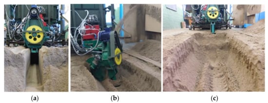
Figure 3.
Experimental studies on the physical model of the operating equipment: (a) a profile of the developed trench; (b) the operating process when constructing a wide excavation; (c) a profile of a wide excavation during one or two passes.
Ditches in the soil are constructed by the operating equipment of the machinery during one or two passes in the soil (Figure 3b,c).
There is practically no residual spillage in the trench of the minimum width, which is equal to the width of the rotor B = 0.6 m. Residual spillage in the ditch (B = 4.5 m) reaches 5–7% of its volume (in-kind).
The load of the UEM operating equipment depends on a number of factors that determine the machinery operating modes, soil conditions, and face parameters.
When conducting the research, the main variables determining the actuator load were established:
- The actuator supply speed to the face, Vs;
- Soil cutting speed, Vc;
- The speed of the actuator lateral supply to the face, Vl.m;
- The time of the intermediate frame additional rotation when the rotor frame rotation mechanism is stopped at the end of each half cycle, tar;
- Soil strength according to Road Scientific and Research Institute DorNDI impactor, C;
- The width of the excavated trench at the level of the daily surface soil, b.
The soil strength C according to the DorNDI impactor is a universal integrated characteristic of soils (both unfrozen and frozen) based on the complexity of their mechanical development. The classification of soils according to the complexity of their development (according to the impactor indicator-DorNDI density meter) was suggested by professor A.M. Zelenin [29].
As a result of experimental research of the operating equipment, it was found that the maximum load of the operating equipment occurs when developing the soil near the lateral walls of the excavation at the end of each half cycle. To evaluate the load peculiarities of the UEM operating in the translational and rotational mode of the actuator supply to the face, the most interesting is the value and points of applying the maximum load on the operating equipment, depending on the value and combinations of factors that determine it.
The processing of the results of experimental studies, according to a special program, made it possible to create regression models for determining the maximum values of the torque Mt on the rotor axis, the traction force T, and the turning moment in the plan Mxoy relative to the intermediate frame mounting swivel on the base chassis. Regression models for determining the maximum values of the parameters listed above have the following form:
The variables in the obtained equations are: x1—the soil strength according to the DorNDI impactor, x2—the trench width, x3—the time of the intermediate frame additional rotation at the end of each half cycle, x4—the speed of the actuator lateral supply to the face, x5—soil cutting speed, and x6—the speed of the actuator supply to the face.
To perform the calculations, it is necessary to use the values of the variables according to the mode studied into each equation. The absolute values of each of the variable factors are within −1 and +1, according to the coding in Table 1.

Table 1.
Coding of variable factors.
After substituting the coded values of the variables into the formulas, the maximum values of the load parameters in the considered modes are obtained. The maximum values of the variables given in the table determine the limiting conditions for applying the obtained regression models, the confidence interval of which is 0.95 with a measurement error of 10%.
The torque on the rotor relative to the axis of its rotation (hereinafter—on the rotor) Mt is one of the main parameters of the UEM operating equipment load. Special attention should be paid to the determination of the nature of changes in its value during the operating cycle (half-cycle) in different modes of operation, in different soil conditions, with additional rotation of the intermediate frame at the end of each half-cycle and without it.
According to the results of experimental studies, it was established that the nature of the Mt change during the cycle (half-cycle) remains the same in different modes of operation, if there is no additional rotation of the intermediate frame and the absolute torque values change. Figure 4 shows graphical dependences of the Mt change during the cycle in different operating modes.
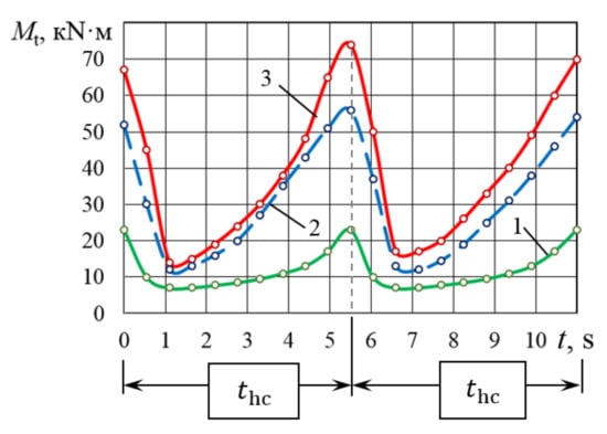
Figure 4.
The torque change on the rotor during the cycle without additional rotation of the intermediate frame s: 1 − Vs = 27 m/h, Vc = 6 m/s; 2 − Vs = 104 m/h, Vc = 9 m/s; 3 − Vs = 104 m/h, Vc = 6 m/s.
The most loaded is the mode of the highest efficiency when developing the soil by a rotor with a cutting speed Vc = 6 m/s, Vl.m = 0.7 m/s. The Mt maximum value is 74 kN·m, the minimum is 14 kN·m, i.e., the torque change coefficient for the half-cycle kMt is 5.28. At the time of changing the direction of the rotor lateral movement, the torque is reduced from maximum to minimum within 1.1 and 1.5 s.
Increasing the soil cutting speed to 9 m/s reduces the torque on the rotor, especially its peak values. Thus, the Mt maximum value decreases to 52–56 kN·m, i.e., by 24–30%, the minimum value decreases to 12 kN·m, i.e., by 14%.
Reducing the speed of the longitudinal supply of the actuator to the face from 104 m/h to 27 m/h, other things being equal, reduces both the torque maximum values to 22–23 kN·m (average by 70%) and the torque change factor up to 2.8, i.e., by 47%.
When the rotor approaches the side wall of the face, the buckets separate the shavings of maximum thickness from the ground by both the side and front borders of their cutting edges.
The forces of digging the soil with buckets are maximum. The rotor buckets are fully filled with soil, the friction forces of the soil transported from the face for unloading in buckets and pressed to the face surface by centrifugal forces are also maximum, as well as the soil weight risen in buckets from the face for unloading. The force of pressing the rotor to the side wall of the excavation is also maximum, and at this point, there is a soil prism between them formed by the lateral movement of the rotor in the face. The formation of the specified prism is completely random in the real operating conditions of the machinery and does not have its own analytical description. It is logical to conclude that the values of the friction force of the prism soil against the side borders of the buckets are maximum at this time. The maximum values of the above-mentioned forces determine the maximum value of torque on the rotor (Figure 4).
At the beginning of return lateral movement of the rotor from a side wall of a ditch the soil is not excavated by cutting edges of buckets. The buckets remain filled with soil, the soil is selected from the prism left between the rotor and the side wall of the face. In this case, the torque on the rotor is determined by the soil weight in the buckets and the soil friction in the buckets against the surface of the face. As the buckets are unloaded, the values of these forces decrease sharply, and during 0.8–1.1 s, the torque on the rotor axis decreases to a minimum value.
According to the experimental dependence 1 (Figure 5), there is a zone of slight change in torque on the rotor axis when the actuator moves on the face. The reason for this is that at a speed of longitudinal supply of the actuator to the face of 27 m/h, the rotor buckets cut thin shavings. As a result, the excavation forces change little, as does the soil mass in the buckets. As the rotor approaches the side wall of the soil excavation, the filling of the buckets with soil increases, including from the side prism, as well as the value of the excavation forces. This leads to a sharp increase in torque on the rotor drive.
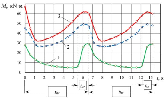
Figure 5.
The torque change on the rotor during the cycle with the additional rotation of the intermediate frame tar = 1.1 s: 1 − Vs = 27 m/h, Vc = 6 m/s; 2 − Vs = 104 m/h, Vc = 9 m/s; 3 − Vs = 104 m/h, Vc = 6 m/s.
The experimental dependences of the Mt change on the rotor during the operating cycle in the same modes (but with the additional rotation of the intermediate frame) are shown in Figure 5.
The nature of these dependencies is similar to the previous ones shown in Figure 4; however, there are differences. They refer to the absolute values of the response function. The Mt maximum values on the rotor are 58–60 kN·m (curve 1), i.e., 20% less than when operating in the same mode without the additional rotation of the intermediate frame. The torque minimum value is 33 kNH·m, i.e., 35% more than when operating without delay. From this, it can be concluded that when operating with the additional rotation of the intermediate frame, the torque values on the rotor are equalized during the half-cycle—the transformation coefficient of the torque change decreases significantly (kMt = 1.8) as well as the torque peak absolute values.
The obtained results enable to assert the rationality and expediency of the machinery in modes with the additional rotation of the intermediate frame during a certain period of time at the end of each half-cycle. This time is indicated on the graphs as the delay time of the rotor frame rotation tar. When the soil is developed with the additional rotation of the intermediate frame, the nature of the forces determining the UEM rotor load by torque remains unchanged. The degree of influence of each of these forces on the torque value on the rotor each time is different compared to the operation of the machinery without the additional rotation of the intermediate frame. The degree of influence of the excavation force increases significantly (Figure 5), and the influence of the drawing prism in front of the rotor is smaller.
Comparing curves 2 and 3 with curve 1 (Figure 5), it can be noted that in 1.1–1.3 s, from the beginning of the rotor movement from the side wall of the trench in some cases (curves 2 and 3), the values of Mt on the rotor increase, and then with the additional rotation, they remain practically unchanged. Otherwise (curve 1), the torque on the rotor decreases and increases only when the intermediate frame is additionally rotated. This indicates that in modes 2 and 3, the delay time of the intermediate frame rotation is insufficient compared to the required one for complete alignment of the shaving thickness. As a result, when the rotor moves on the face, the shaving thickness is increased, not aligned. This causes an increase in the value of all forces determining the torque value. The geometric interpretation of the Mt change during the half-cycle (Figure 6) in mode 1 shows that the delay time tar = 1.1 s is too long for soil development with a longitudinal supply rate Vs = 27 m/h. Thus, when the actuator moves laterally in the face, the shaving thickness cut by buckets is decreased, with all the consequences of this process.
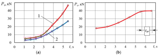
Figure 6.
Change in the vertical force on the rotor during the half-cycle: (a) 1 − Vs = 104 m/h, Vc = 6 m/s, tar = 0 s; 2 − Vs = 104 m/h, Vc = 9 m/s, tar = 0 s; (b) Vs = 104 m/h, Vc = 6 m/s, tar = 1.1 s.
The result of the research is an important conclusion: for each speed of the actuator supply to the face Vs, it is necessary to ensure the time of the additional rotation of the intermediate frame (i.e., its tar). It will equalize the torque value on the rotor during the half cycle and reduce its absolute values. Since during the operation of real machinery the law of Vs change is random even when operating in one gear (different soil density, slippage of the base chassis engines), the uniformity of loads on the rotor (Mt) is ensured only by automatically adjusting the length of the additional rotation of the intermediate frame, depending on the real supply rate of the actuator to the face.
It has been experimentally established that the value of the vertical forces on the rotor during the half-cycle varies according to the parabolic law, and the minimum value of the vertical force is at the beginning of each half-cycle; the maximum one is at the end. The obtained pattern for changes of vertical forces is due to the complex change of excavation forces, soil friction on the face surface, and the soil weight in the rotor buckets depending on the kinematic parameters of the operating process.
In modes without additional rotation of the intermediate frame (Figure 6a), the vertical forces at the beginning of the half-cycle increase evenly due to both a uniform increase in the shaving thickness cut by the cutting edges of buckets and an increase in the speed of the rotor lateral supply to the face during the first half of the half-cycle. In addition, this is explained by the soil prism formed in front of the rotor during its lateral movement. The volume of the prism increases when the rotor approaches the face wall, where, eventually, all the soil is removed by buckets, increasing the load on the rotor drive.
The most loaded is the mode of the highest efficiency at the cutting speed Vc = 6 m/s (Figure 6a); the maximum value is Pv = 45 kN.
The traction force to move the rotor in the face is determined by the excavation forces, friction forces of the transported soil against the face surface, and the inertial loads of the operating equipment.
At the initial moment of the half-cycle, when the longitudinal speed of the operating equipment movement is directed from the face, there is no frontal cutting.
At this time, there are no excavation forces and the rotor buckets in the face are filled with soil. The load on the rotor is determined by the soil inertia forces in the buckets and, to a lesser extent, by the soil friction forces against the face walls. Significant circular speed of soil transportation causes large inertial loads on the rotor because the speed vector of its longitudinal movement is directed from the face (Figure 7a).
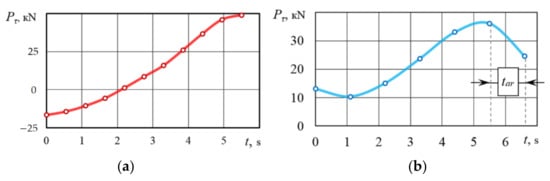
Figure 7.
Change in the traction force on the rotor during the half-cycle: (a) 1 − Vs = 104 m/h, Vc = 6 m/s, tar = 0 s; 2 − Vs = 104 m/h, Vc = 9 m/s, tar = 0 s; (b) Vs = 104 m/h, Vc = 6 m/s, tar = 1.1 s.
When the rotor is removed from the side wall of the soil excavation in the first half of the half-cycle of the actuator lateral movement, the soil is excavated only by the side borders of the buckets. In this case, Vτ is directed from the face, and, as a consequence, the component of the excavation forces from the longitudinal movement of the rotor is directed towards the face, i.e., opposite the machinery movement. With the beginning of lateral cutting of the soil, the traction force on the rotor becomes positive. In the highest efficiency mode (Vc = 6 m/s, Vl.m = 0.7 m/s) without the additional rotation of the intermediate frame, the maximum value of the traction force at the end of the half-cycle is Pτ = 48 kN. When the intermediate frame is additionally rotated, tar = 1.1 s, all other things being equal, the maximum value of the traction force to move the rotor is near the side wall of the face before the additional rotation of the intermediate frame and reaches the value Pτ = 35 kN (Figure 7b). This is 36% less than in the mode without the additional rotation. Under these conditions, the coefficient of variation of the traction force value during the half-cycle is 4.3.
Lateral loads on the rotor are determined mainly by the value of the normal components of the excavation force by the side borders of the cutting elements of buckets. Lateral force is known to be calculated as part of the tangential component of the excavation force. It is characterized by the ψ3 coefficient, which depends both on the kinematic parameters of the digging process (cutting speed and lateral supply speed) and the design of the cutting elements of buckets. In the general case, this coefficient is empirical. The formulas for its definition are given in popular references [14,15,30,31].
The known value of the ψ3 coefficient can not be used in this case to calculate the resistance forces to lateral movement of the UEM actuator because the published research results refer to quarry excavators, the actuators of which operate in fundamentally different conditions [14,15,30,31]. In particular, the side wall of the face during the operation of quarry excavators always remains open. The spillage of the developed rock at the bottom of the face insignificantly affects the formation of loads on the rotor.
The experimentally determined values of the resistance forces to the lateral movement of the UEM rotor in the face for operating modes with soil cutting speeds Vc = 6 m/s and Vc = 9 m/s are shown in Figure 8.
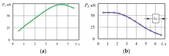
Figure 8.
Change in lateral force on the rotor during the half-cycle: (a) 1 − Vs = 104 m/h, Vc = 6 m/s, tar = 0 s; 2 − Vs = 104 m/h, Vc = 9 m/s, tar = 0 s; (b) Vs = 104 m/h, Vc = 6 m/s, tar = 1.1 s.
4. Discussion
The actual value of the correction coefficient of resistance to the lateral movement of the UEM rotor in the face ψ3 must always be taken into account in engineering calculations of the UEM operating equipment load when digging the soil in modes with or without additional rotation of the actuator.
5. Conclusions
- The physical nature of external loads on the universal continuous earthmoving machinery actuators in the mode of digging the soil has been discovered.
- Based on theoretical and experimental studies of the operating processes of the continuous universal earthmoving machinery, a method for leveling and minimizing external loads on the actuator when digging the soil by improving the kinematics of the actuator rotor movement in the face has been suggested and implemented on a physical model of the operating equipment.
- The results of the performed experimental studies with the analysis of the regression models based on the research results for determining external loads on the UEM actuator confirm the possibility to level and reduce the value of these loads by additional rotation of the actuator intermediate frame at the end of each half-cycle in a wide range of changes in soil conditions and machinery operating modes. The necessary duration of the intermediate frame additional rotation is functionally dependent on the real speed of the machinery movement.
- The additional rotation of the intermediate frame, the duration of which is 1.1 s in the mode of the highest efficiency, reduces the maximum load of the operating equipment, namely: the torque on the rotor axis Mt by 19% (up to 60 kN∙m). Moreover, regarding the components of the main force vector: traction force T reduces by 26% (up to 37 kN), the vertical force reduces by 9% (up to 40 kN), and the lateral force Pl reduces by 32% (up to 58 kN).
- Improving the kinematics of the UEM operating process and, as a consequence, aligning the thickness of shavings cut by the buckets of the rotor actuator for the half-cycle of the UEM operation enable to almost double the efficiency of the universal earthmoving machinery.
- The obtained results provide a comprehensive engineering assessment of the maximum load of the UEM operating equipment under the conditions of changing the value of the factors on which it depends. The research results enable to objectively calculate energy and strength characteristics of the machinery and assess the directional stability of the machinery.
Author Contributions
Conceptualization, V.M., J.G. and M.H.; methodology, J.G., V.M. and M.H.; software, V.M., M.H. and A.K. (Andrii Koval); validation, A.K. (Andrii Koval), A.K. (Anatolii Korpach), and K.K.; formal analysis, M.H., A.K. (Anatolii Korpach), and K.K.; investigation, V.M., J.G., M.H., L.Č., K.K. and V.P.; resources, V.M., M.H., A.K. (Andrii Koval), and A.K. (Anatolii Korpach); writing—original draft preparation, M.H., A.K. (Andrii Koval), K.K., L.Č. and V.P.; writing—review and editing, V.M., A.K. (Anatolii Korpach), and J.G.; visualization, A.K. (Andrii Koval), K.K., V.P. and L.Č.; supervision, V.M., J.G. and A.K. (Anatolii Korpach). All authors have read and agreed to the published version of the manuscript.
Funding
This publication was issued thanks to support from the Cultural and Educational Grant Agency of the Ministry of Education of the Slovak Republic in the projects, “Implementation of modern methods of computer and experimental analysis of properties of vehicle components in the education of future vehicle designers” (Project No. KEGA 036ŽU-4/2021) and “Development of advanced virtual models for studying and investigation of transport means operation characteristics” (Project No. KEGA 023ŽU-4/2020). This research was also supported by the Slovak Research and Development Agency of the Ministry of Education, Science, Research, and Sport of the Slovak Republic in Educational Grant Agency of the Ministry of Education of the Slovak Republic in the project and VEGA 1/0513/22 “Investigation of the properties of railway brake components in simulated operating conditions on a flywheel brake stand” and the support of Operational Program Integrated Infrastructure 2014–2020 of the project: Innovative Solutions for Propulsion, Power, and Safety Components of Transport Vehicles, code ITMS 313011V334, co-financed by the European Regional Development Fund.
Institutional Review Board Statement
Not applicable.
Informed Consent Statement
Not applicable.
Data Availability Statement
Not applicable.
Conflicts of Interest
The authors declare no conflict of interest.
References
- Shehadeh, A.; Alshboul, O.; Tatari, O.; Alzubaidi, M.A.; Hamed El-Sayed Salama, A. Selection of heavy machinery for earthwork activities: A multi-objective optimization approach using a genetic algorithm. Alex. Eng. J. 2022, 61, 7555–7569. [Google Scholar] [CrossRef]
- Dižo, J.; Blatnický, M.; Fiaþan, J.; Semenov, S.; Mikhailov, E. Engineering Design of a Tyre-rail Adapter for a Light Road-rail Vehicle. In Proceedings of the International Conference Transport Means, Online, 6–8 October 2021; pp. 183–187. [Google Scholar]
- Turusbekov, K.; Tusupbekov, M.; Khon, N.; Gabdysalyk, R.; Turusbekov, S.; Zhailaubaev, D. The improvement of the digging process with the sliding surface consideration. Biosci. Biotechnol. Res. Asia 2015, 12, 2995–3008. [Google Scholar] [CrossRef] [Green Version]
- Musiiko, V.D.; Koval, A.B.; Lazaruk, Y.V. Problems, directions and prospects of creating and modernizing continuous earthmoving machinery of special purpose. Sci. Tech. Collect. Her. Natl. Transp. Univ. “Tech. Sci.” Ser. NTU 2021, 1, 223–232. [Google Scholar]
- Mednikov, A.; Bikov, A. The peculiarities of work on PZM-2. Mach. Equip. 1981, 4, 22–23. [Google Scholar]
- Gerlici, J.; Musiiko, V.; Koval, A.; Nikolaenko, V.; Lazaruk, J.; Lack, T.; Kravchenko, K. Experimental analysis of the universal continuous digging machine working processes. Manuf. Technol. 2020, 20, 429–435. [Google Scholar] [CrossRef]
- Kravets, S.V. Soil Protection and Energy Saving Machinery for Laying Underground Communications; RSTU: Rivne, Ukraine, 1999; p. 277. [Google Scholar]
- Kyrychenko, I.G.; Nazarov, L.V.; Nichke, V.V.; Demishkan, V.F.; Pryxodko, V.I. Scientific Bases for Creating Highly Efficient Earthmoving and Transport Machinery; Kharkiv Automobile and Highway Institute (KhAHI): Kharkiv, Ukraine, 2003; p. 588. [Google Scholar]
- Kravets, S.; Suponyev, V.; Goponov, A.; Kovalevskyi, S.; Koval, A. Determination efficient operating modes and sizes of blades for multi-scrapertrench excavators. East.-Eur. J. Enterp. Technol. 2020, 4, 106. [Google Scholar] [CrossRef]
- Ha, Q.P.; Yen, L.; Balaguer, C. Robotic autonomous systems for earthmoving in military applications. Autom. Constr. 2019, 107, 102934. [Google Scholar] [CrossRef]
- Kadyrov, A.S.; Amangeldiev, N.E. New specifications of the theory of ground cutting. Period. Tche Quim. 2019, 16, 922–936. [Google Scholar] [CrossRef]
- Carevskij, V.I. Multi-Bucket Excavator Russian Patent 277631, Application No. 1224782/29-14, 22 June 1970.
- Mihlevskij, A.I.; Kavalerov, A.A.; Sidorov, K.I.; Lisnovskij, B.G.; Kvach, A.A.; Suchenko, V.G.; Ivanov, I.I.; Guzenko, N.N.; Red’ko, D.L.; Shevchenko, G.V.; et al. Trench Digging Machinery Russian Patent 184732, Application No. 1002187/29-14, 21 July 1966.
- Dombrovsky, N.G. Multi-Bucket Excavators. Design, Theory, Calculation; Mechanical Engineering: Moscow, Russia, 1972; p. 432. [Google Scholar]
- Vladimirov, V.M.; Trofimov, V.N. Improving the Efficiency of Quarry Multi-Bucket Excavators; Nedra: Moskow, Russia, 1980; p. 312. [Google Scholar]
- Liu, Q.; Lu, C.; Liu, T.; Xu, Z. Adaptive Cutting Control for Roadheaders Based on Performance Optimization. Machines 2021, 9, 46. [Google Scholar] [CrossRef]
- Wang, P.; Shen, Y.; Ji, X.; Zong, K.; Zheng, W.; Wang, D.; Wu, M. Multiparameter control strategy and method for cutting arm of roadheader. Shock Vib. 2021, 2021, 9918988. [Google Scholar] [CrossRef]
- Jasiulek, D.; Stankiewicz, K.; Šwider, J. An adaptive control system of roadheader with intelligent modelling of mechanical features of mined rock. J. KONES Powertrain Transp. 2011, 18, 197–203. [Google Scholar]
- Diep, D.D. Analysis the factors affecting conveyance rate of unbucket chain trenching machine. Agric. For. Transp. Mach. Technol. 2017, 4, 38–44. [Google Scholar]
- Smager, I.V.; Sakhno, B.G.; Bykov, A.V.; Glazman, B.M.; Musiiko, V.D.; Morozov, S.A.; Stankevich, G.N.; Yatsenko, V.M. A Device for Automatic Control of the Loading Mode of A Universal Earthmoving Machinery. Russian Patent 1677195, Application No. 4625587, 15 September 1991. [Google Scholar]
- Palomba, I.; Richiedei, D.; Trevisani, A. Estimation of the digging and payload forces in excavators by means of state observers. Mech. Syst. Signal Progress. 2019, 134, 106356. [Google Scholar] [CrossRef]
- Moczko, P.; Pietrusiak, D.; Wieckowski, J. Investigation of the failure of the bucket wheelexcavator bridge conveyor. Eng. Fail. Anal. 2019, 106, 104180. [Google Scholar] [CrossRef]
- Bykov, A.V.; Kotsuba, Y.G.; Glazman, B.M.; Lisnovsky, B.G.; Sidorov, K.I.; Saluk, L.V.; Loboda, V.A.; Maksimov, V.A.; Suvorov, V.V. Earthmoving Machinery Russian Patent 1137157, Application No. 3581844/29-03, 30 January 1985.
- Dmytrychenko, M.F.; Musiiko, V.D.; Bilyakovych, M.O.; Leichenko, Y.B.; Koval, A.B.; Kuzminets, M.P. Universal Earthmoving Machinery Ukranian Patent 101931, Application No. a 2012 09065, 13 May 2013.
- Musiiko, V.D.; Koval, A.B.; Leichenko, Y.B. Fundamentals of synthesis of layout scheme for universal continuous earthmoving machinery. In Systemy i srodki transportu samochodowego. Wubrane zagadnienie; Kazemierza, L., Ed.; Monografia Nr 4. Seria; Politechnika Rzeszowska: Rzeszów, Poland, 2015; pp. 263–268. [Google Scholar]
- Musiiko, V.; Šťastniak, P.; Honchar, M.; Nikolaienko, V.; Lazaruk, J.; Korpach, A.; Suchánek, A. Optimization of the Motion Algorithm and Reduction of the External Dynamic Load of the Machinery Actuator in Translational and Rotational Modes. Symmetry 2022, 14, 51. [Google Scholar] [CrossRef]
- Balovnev, V.I. Methods for Physical Modeling of Operating Processes of Road Construction Machinery; Mechanical Engineering: Moskow, Russia, 1974; p. 232. [Google Scholar]
- Balovnev, V.I. Modeling the Processes of Interaction of Road Construction Machinery Actuators with the Environment; Higher School: Moskow, Russia, 1981; p. 335. [Google Scholar]
- Zelenin, A.N. Fundamentals of Soil Destruction by Mechanical Methods; Mechanical Engineering: Moskow, Russia, 1968; p. 432. [Google Scholar]
- Vladimirov, V.M.; Shenderov, A.I.; Kalashnikov, Y.T.; Khazanet, L.L.; Slizky, P.I.; Sereda, G.L. Quarry Rotor Excavators; Machinery: Kiev, Ukraine, 1968; p. 282. [Google Scholar]
- Vladimirov, V.M. Determining the values of lateral cutting force in calculations of rotor excavators. Open Pit Coal Min. 1966, 11, 14–17. [Google Scholar]
Publisher’s Note: MDPI stays neutral with regard to jurisdictional claims in published maps and institutional affiliations. |
© 2022 by the authors. Licensee MDPI, Basel, Switzerland. This article is an open access article distributed under the terms and conditions of the Creative Commons Attribution (CC BY) license (https://creativecommons.org/licenses/by/4.0/).