Abstract
In this article, we propose a new approach utilizing diffuse optical tomography (DOT) to monitoring the changes in tissues’ optical properties and temperature in high-intensity focused ultrasound (HIFU) therapy. By correlating the tissue reduced scattering coefficient () reconstructed by DOT and the temperature measured by a thermocouple, the quantitative relationship between and temperature in HIFU treatment was explored. The experiments were conducted using porcine and chicken breast muscle tissues during HIFU; the temperature of each tissue sample was recorded using a thermocouple. To incorporate the temperature dependency of tissue optical properties, both polynomial and exponential models were utilized to fit the experimental data. The results show that the change of during HIFU treatment could be detected in real-time using DOT and that this change of is quantitatively correlated with tissue temperature. Furthermore, while the tissue-type-dependent relationship between and temperature is non-linear in nature, it is stable and repeatable. Therefore, our approach has the potential to be used to predict temperature of tissue during HIFU treatment.
1. Introduction
High-intensity focused ultrasound (HIFU), as a mature medical technology for conducting non- or minimally invasive tumor ablation therapy, is capable of inducing biological effects deep in the body by delivering acoustic energy with a millimeter-sized focal region []. In the past few decades, HIFU has been applied in high temperature thermal therapy to ablate solid malignant tumors in various organs, such as the prostate [,], breast [], liver [], pancreas [] and uterine fibroids []. While the research interest in HIFU for hyperthermia has declined, the application of HIFU for the treatment of tremors [,], opening the BBB [,] and helping immunotherapy [,] has gained a lot of research interest lately and has been rapidly developing. In HIFU therapy, the energy deposited by absorbing ultrasound energy in tissue can be transformed into thermal energy and quickly elevates the tissue temperature, eventually leading to the ablation of the targeted lesions.
The measurement of temperature plays a critical role in thermal therapy, providing real-time feedback with which to optimize the acoustic parameters (location, duration, intensity, etc.) during the HIFU treatment. This real-time feedback of the temperature helps to optimize treatment efficacy while minimizing the damage to the normal tissues surrounding the lesion. A thermocouple was the most common tool that was previously used for monitoring the temperature of tissue in HIFU treatment. Although this typically used tool has many advantages, such as low cost and high precision, there are several drawbacks. First of all, thermocouples only can measure the temperature at just one point. Secondly, it is impossible to invasively measure the temperature deep in the tissue utilizing a thermocouple. An alternative tool with which to measure temperature is a thermal imaging camera. While the thermal imaging camera provides two-dimensional (2D) measurement of temperature with high precision, the superficial measurement on the surface highly limits its application in HIFU therapy. Recently, magnetic resonance (MR)-guided high-intensity focused ultrasound (MR-HIFU) treatment, an image guided technique which combines high-intensity focused ultrasound ablation with real-time monitoring of temperature change during the treatment [,,], was approved by the Food and Drug Administration (FDA) for the treatment of osteoid osteoma in the extremities [,]. Although this treatment modality is encouraging, MRI is too expensive in most situations and still has limitations in spatial and temporal resolutions in temperature measurement. Moreover, spatial and temporal averaging of the measured temperature can lead to an underestimation of the temperature and errors in the estimation of the thermal dose. Another limitation of this method is that it measures only temperature change rather than absolute temperature. Although there have been some developments in this field [,,], measuring the absolute temperature is very challenging. It is for these reasons that an alternative approach for non-invasive volumetric temperature measurement is desired.
Optical properties of tissue, including the absorption coefficient () and the reduced scattering coefficient (), provide sufficient information to monitor tissue metabolic status or diagnose disease. Characteristic changes in tissue optical properties can be indicative of disease, which is due to the thermal dissociation of phospholipid cellular membranes and thermal denaturation of intracellular and extracellular proteins when heat is applied to tissue [,,,]. It was reported that the first change in optical properties was detected at 45 °C and that there were a 2-fold increase and 7-fold increase in absorption and scattering, respectively, at temperatures above 65 °C []. Therefore, it is conceivable that an alternative approach could be realized by measuring the changes in optical properties, especially , as a function of temperature. Integrating sphere measurement is a common method to measure the optical properties of tissue. However, this method is invasive and measures temperature only at one point. Near-infrared (NIR) diffuse optical tomography (DOT) is a convenient and cost-effective optical imaging modality, and has the potential to become a powerful tool in biomedical research and clinical studies [,]. Due to the use of an effective model-based reconstruction algorithm, DOT is able to provide accurate visualization and quantification of the three-dimensional (3D) distribution of intrinsic tissue absorption and scattering properties in deep turbid tissue with good spatial and temporal resolution. Over the last several decades, DOT has been widely applied to many clinical areas, including the detection of breast cancer [,], arthritis [,] and functional brain activities [,,]. Recently, we have developed and reported a powerful fast multispectral DOT imaging system which allows for a full set of 3D data that is collected utilizing 3 NIR wavelengths (660, 780 and 850 nm) for the purpose of real-time imaging in 14.4 Hz [,] (pages 7 and 8 in reference [], and pages 3462–3465 in reference []). Extensive phantom and clinical experiments have demonstrated and verified that this fast DOT imaging system is able to recover both structural and functional information from both animal and human brains.
The goal of this study is to present a new approach based on DOT to monitoring the heating process during HIFU treatment and to investigating the feasibility of an alternative approach to predict the temperature change of tissue. Using a fast DOT imaging system, the effects of temperature-dependent optical property (i.e., reduced-scattering coefficient, ) on temperature distribution within tissue during HIFU treatment were investigated by extensive experimentation on both porcine and chicken breast muscle specimens.
2. Materials and Methods
2.1. Image Reconstruction Algorithm
Two steps were required in this study. The first step was to perform DOT. In DOT, both the absorption and scattering coefficient images were recovered from an iterative finite element (FEM)-based algorithm, as previously described in detail by Jiang et al. [] (pages 9–15). The photon diffusion equation which is coupled with Robin boundary conditions,
is discretized and solved by using finite element method, where is the photon density, S(r) is the source term, is the absorption coefficient, and D is the diffusion coefficient. The diffusion coefficient can be written as , where is the reduced scattering coefficient and is the boundary condition (BC) coefficient related to the internal reflection at the boundary. Then, a regularized Newton’s method is used to update an initial optical property distribution iteratively in order to minimize a weighted sum of the squared difference between computed and measured optical data along its boundary.
The core procedure in our reconstruction algorithms is to iteratively solve the following regularized matrix equation:
where J is the Jacobian matrix that is formed by / and / at the boundary measurement sites, I is the identity matrix, and is the regularization parameter determined by combined Marquardt and Tikhonov regularization schemes. is the update vector for the optical property profiles, where N is the total number of nodes in the finite element mesh. and are the measured and computed photon density, respectively. A three-dimensional cylindrical FE mesh of 700 nodes was used for the image reconstruction. The reconstruction algorithm converged within nine iterations in a GPU (graphics processing unit) parallelized computer with 8 GB RAM (random-access memory).
The second step is to establish the relationship of the reduced scattering coefficient obtained by DOT and the tissue temperature measured by a thermocouple. Since the first change in optical properties was detected at 45 °C [], only the data when the temperature was higher than 45 °C was utilized in this study. In this step, the DOT data from five tissue samples were fit to a two-degree polynomial () or two-term exponential model (), in which a, b, c and d are the coefficients. Due to the non-linear relationship between the temperature and as observed in the experimental data, the entire heating process was divided into two steps in the fitting with the polynomial model (1st step: 45 to 54 °C, 2nd step: 54 to 59 °C), whereas only one step was needed in the exponential model (45 to 59 °C). Once this relationship was established, the temperature of a tissue could be estimated using this relationship. To verify the performance of each method, the temperatures predicted by different fitting models were compared with those measured by thermometer using other five separate tissue samples. Additionally, the root mean square error (RMSE) between the measured and predicted temperature was calculated to evaluate the precision of each fitting model.
2.2. Experimental System
The experimental system used for this method was the same as that for DOT. Figure 1 illustrates the schematic of our fast DOT system, which was reported and described in detail previously [] (pages 7 and 8). Briefly, the light beams from forty-eight high-power NIR LEDs (Epitex, Inc., Kyoto, Japan) at a wavelength of 780 nm were delivered sequentially to forty-eight source positions on the interface via optical fiber bundles. The diffused light received by the detection fiber bundles was detected by high-sensitivity avalanche photodiodes (APDs) (Hamamatsu, El Cajon, CA, USA, C5460-01) and then collected through a data acquisition system (NI, PXI-6358). A field programmable gate array (FPGA) core board (NI, PCI-7811R) was used to control the LED timing sequence and synchronize the data acquisition of the whole system. The output power of LEDs was adjustable through a DC power supply to achieve optimal signal-to-noise ratio (SNR). The photograph inserted in Figure 1 shows the cylindrical optical fiber interface. Forty-eight optical source/detector pairs were distributed equally along the interface with an inner diameter of 4 cm. A single-element, spherically concaved HIFU transducer (H-101, Sonic Concept, Bothell, WA, USA) with a center frequency of 1.1 MHz and focal length of 5 cm was used to treat tissue samples in this study. The transducer had a 64 mm aperture and 62.4 mm radius of curvature. An electrical radiofrequency (RF) signal (sine wave: 1.1 MHz; ±10 V peak-to-peak voltage) generated by an arbitrary function generator (AFG3022B, Tektronix, Beaverton, OR, USA) was amplified by an RF power amplifier (PAB LA0005-10, Delta RF technology, Reno, NV, USA; 10 W output) and then was unitized to drive the HIFU transducer. To record the temperatures invasively, a T-type thermocouple (Omega engineering Inc., Norwalk, CO, USA, TJC36-CPSS-020G-6) with a diameter of 500 μm was inserted into the sample close to the HIFU focus point, and the measured temperature values were synchronously sent to and acquired by the computer through a USB cable. A LabVIEW program was developed to control both the DOT imaging and thermocouple measuring systems.
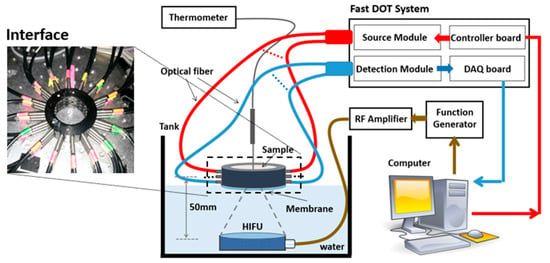
Figure 1.
The schematic of the fast DOT system for temperature measurement.
To alleviate the impact of water temperature on the tissue samples, a membrane attached to the bottom of DOT interface was used not only to hold the sample tissues but also to insulate the tissues from water. The water level was carefully adjusted to just reach to the membrane in order to realize good coupling of acoustic signal between water and sample tissues. As the focal length of the HIFU transducer is known and it was easy to determine the focal zone in the water, the relative positions of the HIFU transducer, DOT interface and thermocouple could be set and fixed prior to the HIFU experiments in the water tank without a tissue sample. The HIFU focal point was set to the center of the DOT interface. Then, the water level was adjusted to be the same height as the membrane attached to the DOT interface, which also served as a position marker for the DOT interface in the subsequent experiments. The thermocouple was fixed on a manual translation stage which could move vertically. A marker indicating the insert depth in the tissue was made on the probe to make sure that the thermocouple reached to the focal point of HIFU. Due to the miniaturized size of the thermocouple, its interference on DOT data collection was minimal. A calibration method further alleviated the noise from the thermocouple to the DOT recording []. We were careful about the repeatability of thermocouple positioning in tissue and minimized the impact on the temperature measurement using a motion control system with high precision (<0.5 mm), giving the relatively larger focal zone of the HIFU (~4 mm). The measured temperature data shown in the next section indicate that our temperature measurement is repeatable. Moreover, averaging of in an area with a diameter of 3 mm was performed to stand for the value at the HIFU focus point. Therefore, the impact due to the displacement of thermocouple was further alleviated.
In this study, either porcine or chicken breast was cut and placed into the interface as the HIFU treatment target. To ensure good contact and optical coupling between the optical fibers/sample, the gap between the head and the fiber interface was filled with Intralipid/India ink solution.
3. Results and Discussion
In order to find the reliable relationship between temperature and , ten porcine and ten chicken breast tissues were treated by HIFU for 10 min. The temperature and the of the tissues were measured by utilizing the setup described in Section 2. Then, we fit two different models (polynomial and exponential model) to five sets of data for each type of tissue. Finally, we compared the calculated temperature with the measured temperature from the remining five sets of tissues to verify the precision of those methods to predict temperature.
3.1. Porcine Muscle Tissue
Figure 2a shows a photograph of a porcine muscle tissue treated by HIFU for 10 min, in which the HIFU caused a spot of damage with a diameter of 4 mm that could be observed clearly (indicated by the arrow). The reconstructed images in XY and YZ plane are shown in Figure 2b. It was observed that there was a roughly 3-fold increase in scattering when the temperature reached 55.8 °C. The measured temperature and reconstrued value around the HIFU focus point are shown in Figure 2c,d, respectively.
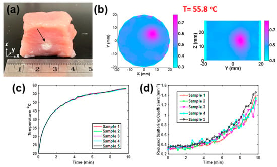
Figure 2.
(a) Photograph of a porcine sample treated by HIFU along the z-axis. (b) Recovered distribution in XY and YZ planes (t = 55.8 °C). (c) Temperature versus time and (d) recovered versus time of five porcine samples treated by HIFU in 10 min per sample.
Next, two-degree polynomial and two-term exponential models, as shown in Figure 3 (left), were utilized to fit to the temperature and data of five porcine tissue samples. Figure 3a,c shows the fitting curves (solid lines) with the polynomial and exponential models, respectively, and the average temperature- data (blue circles) measured from five porcine muscle tissues treated by HIFU. In Figure 3a, it is shown that there were no obvious changes in when the temperature was lower than 45 °C, which means that the heating from the HIFU radiation did not yet cause any damage to the tissue. Therefore, we only utilized the data from when the temperature was higher than 45 °C. Meanwhile, we also noticed that the increased dramatically when the temperature was in the range of 45–54 °C. When the temperature was higher than 55 °C, the change in was slower. Based on these noted differences in the effects of , the whole process was divided into two steps in the fitting with the polynomial model (1st step: 45 to 54 °C, 2nd step: 54 to 59 °C). In order to verify the precision of the created models, we compared the calculated temperatures (by (b) polynomial and (d) exponential methods, solid line) with those measured by thermometer (scattered points) for another five samples. Furthermore, the root mean square error (RMSE) was calculated to measure the performance of each fitting model, and results are shown in Table 1. It is shown that for the polynomial model, the average RMSE of five samples was 1.87 °C in the 1st step, and it was 0.44 °C in the 2nd step. For the exponential model, the RMSE was 1.14 °C.
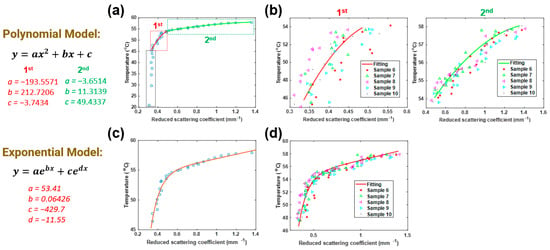
Figure 3.
Fitting (a) polynomial model and (c) exponential model to measured DOT data of porcine muscle tissues. Comparison between the temperatures calculated/predicted by (b) polynomial and (d) exponential methods (solid line), and those measured by a thermometer (scattered points) as a function of .

Table 1.
Root mean square error (RMSE) of five porcine muscle tissues (units: °C).
3.2. Chicken Breast Muscle Tissue
Similarly to Section 3.1, Figure 4a shows the photograph of a chicken breast muscle tissue treated by HIFU for 10 min. The damage spot caused by HIFU (indicated by arrow) had a diameter of 5 mm. The reconstructed images in the XY and YZ plane are shown in Figure 4b. It is shown that increased almost 2.5-fold by the time the temperature reached 54.8 °C. The measured temperature and reconstrued values around the HIFU focus point are shown in Figure 4c,d, respectively.
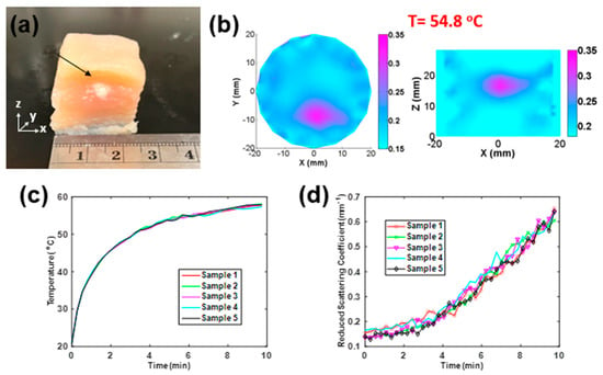
Figure 4.
(a) Photograph of a chicken breast sample treated by HIFU along the z-axis (b) Recovered distribution in XY and YZ planes (t = 54.8 °C). (c) Temperature versus time and (d) recovered versus time of five chicken breast samples treated by HIFU in 10 min per sample.
Figure 5 shows the details of the two-degree polynomial and the two-term exponential models. Figure 5a,c shows the fitting curves (solid lines) with the polynomial and exponential models, respectively, along with the average temperature- data (blue circles) taken from five porcine muscle tissues treated by HIFU for 10 min per sample. We also utilized the data similarly when the temperature was higher than 45 °C. In the polynomial model, the whole process was divided into two steps (1st step: 45 to 54 °C, 2nd step: 54 to 59 °C). Then, we compared the calculated temperature (by (b) polynomial and (d) exponential method, solid line) with the measured data (scattered points) of another five samples. Finally, the RMSEs based on chicken breast tissues were calculated, and the results are displayed in Table 2. It was 1.67 °C in the 1st step and 0.39 °C in the 2nd step for the polynomial model. For the exponential model, the RMSE was 0.94 °C.
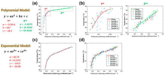
Figure 5.
Fitting (a) polynomial model and (c) exponential model to measured DOT data of chicken breast muscle tissues. Comparison between the temperatures calculated/predicted by (b) polynomial and (d) exponential methods (solid line) and those measured by a thermometer (scattered points) as a function of .

Table 2.
Root mean square error (RMSE) of five chicken breast samples (units: °C).
We noticed the difference in the fitting results between the chicken breast and porcine samples. The reason for this difference is likely due to the nonlinear relationship between temperature and optical properties. It may also be related to the differences in acoustic properties (especially acoustic absorption coefficient) of the two different tissues. In addition, we studied the changes in when HIFU was off and temperature decreased. The results showed only a slight decrease in with the drop in temperature. The reason is that the optical property changes due to the tissue damage under HIFU treatment are irreversible. While the heating source was revoked and temperature dropped, the optical properties of tissue could not fully recover anymore.
It is noted that the relationship between and temperature established above allows us to obtain the temperature distribution of a tissue sample from the image of the sample. To achieve this goal, the values within the image domain were classified into a few different ranges and then mapped into temperatures using the methods shown in Table 3. As we only established the relationship between and temperature between 45 and 59 °C in this study, the tissue temperature was set to be the ambient temperature (i.e., 21 °C) if the value was lower than that at 45 °C. The temperature maps of porcine and chicken breast muscle samples at 10 min after HIFU treatment were obtained based on the polynomial model and exponential model, and the resulting temperature maps are shown in Figure 6.

Table 3.
Mapping between and temperature (T) (P_1st: fittings using polynomial model in the 1st stage; P_2nd: fittings using polynomial model in the 2nd stage).
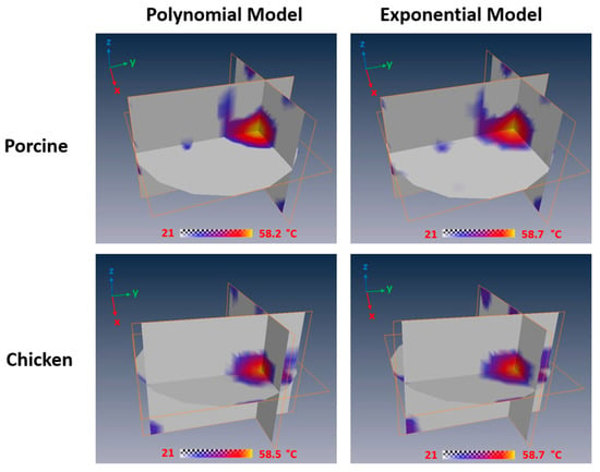
Figure 6.
Temperature maps of porcine and chicken breast muscle at 10 min after HIFU treatment based on the polynomial model and exponential model.
In addition to the temperature estimation, the real-time optical property changes in tissue imaged by DOT themselves could be directly utilized as indicators of HIFU treatment progression to optimize the treatment. Furthermore, the quantitative correlation between and temperature indicates that this approach has the potential to predict tissue temperature at the HIFU focal point during HIFU therapy. While these results are promising, we still noticed that the precision of the temperature prediction by utilizing this method is not good as that of traditional thermometry, such as a thermocouple. By increasing the temporal resolution of the DOT imaging system, the recovered volumetric distribution will be more stable and prone to less errors by applying more averaging. Therefore, the precision of temperature prediction will increase when the temporal resolution is increased. Additionally, we noticed that a limitation of this approach is that the relationship between temperature and is nonlinear, which adds the complexity of this approach. The primary reason is that the changes in optical properties are directly related to thermal dose. Therefore, it may cause delays in optical property changes with temperature. However, if all parameters associated with HIFU stay the same, the whole treatment process should be repeatable, which has been demonstrated by the extensive experiments presented in this work. Thus, this nonlinear relationship between temperature and optical property () still could be used to predict the temperature changes during HIFU treatment. Considering the advantages this method has, such as noninvasive imaging, low cost and volumetric information, this DOT-based method is a good approach to monitoring the temperature changes during thermotherapy sessions.
To establish a more robust relationship between and temperature in our future study, we plan to utilize multiple thermocouples to measure the temperature at different positions. We can also consider using a thermal camera to measure a two-dimensional (2D) temperature distribution on the tissue surface. These additional temperature data measured at the locations away from the HIFU focal zone could be utilized as references to calibrate the correlation analysis and to improve the accuracy of the temperature prediction using DOT. To achieve this, our hardware system needs to be upgraded with a new DAQ subsystem with more physical channels. In future, we will apply this approach to study on in vivo animals and humans. Our ultimate goal is to provide strong evidence that DOT could be used as an alternative to monitor the entire treatment process in HIFU therapy, and to establish a robust relationship between tissue optical properties and temperature for predicting temperature distribution of in vivo tissue during HIFU treatment.
4. Conclusions
In summary, we have provided evidence that DOT can be utilized as a new approach to monitor the heating process in HIFU therapy. Furthermore, correlation was performed to establish the quantitative relationship between recovered by DOT and temperature measured by a thermocouple. Extensive ex vivo animal tissue tests (with porcine and chicken breast muscle tissue) were conducted to illustrate the capability of DOT to image changes in real-time during HIFU therapy. The optical property changes were monitored using a fast DOT imaging system and then reconstructed using a FEM-based DOT algorithm while the temperature was detected and verified by using a thermocouple simultaneously. The temperature-to- conversion for DOT imaging in the 45 to 60 °C temperature range was described by a two-degree polynomial and two-term exponential models. The results showed good agreement between the measured and predicted temperature rises, which indicates that this approach based on DOT has the potential to be used for noninvasive, real-time temperature monitoring during HIFU therapy.
Author Contributions
Conceptualization, H.J. and H.Y.; methodology, H.Y.; software, H.J., H.Y. and S.A.; validation, H.Y. and S.A.; formal analysis, H.Y. and S.A.; writing—original draft preparation, H.Y.; writing—review and editing, S.A. and H.J.; visualization, H.Y. and S.A.; project administration, H.J. All authors have read and agreed to the published version of the manuscript.
Funding
This research was funded in part by the University of South Florida.
Institutional Review Board Statement
Not applicable.
Informed Consent Statement
Not applicable.
Data Availability Statement
Not applicable.
Conflicts of Interest
The authors declare no conflict of interest.
References
- Ter Haar, G. Ultrasound focal beam surgery. Ultrasound Med. Biol. 1995, 21, 1089–1100. [Google Scholar] [CrossRef]
- Poissonnier, L.; Chapelon, J.-Y.; Rouvière, O.; Curiel, L.; Bouvier, R.; Martin, X.; Dubernard, J.M.; Gelet, A. Control of Prostate Cancer by Transrectal HIFU in 227 Patients. Eur. Urol. 2007, 51, 381–387. [Google Scholar] [CrossRef]
- Aus, G. Current Status of HIFU and Cryotherapy in Prostate Cancer—A Review. Eur. Urol. 2006, 50, 927–934. [Google Scholar] [CrossRef] [PubMed]
- Chen, S.; Bian, H.; Duan, J. High-Intensity Focused Ultrasound Enhanced Anti-Tumor Activities of Paclitaxel in Breast Cancer in vitro and in vivo. Cancer Manag. Res. 2022, 14, 1303. [Google Scholar] [CrossRef] [PubMed]
- Zhao, L.Y.; Chao, X.; Yang, B.S.; Wang, G.; Zou, J.; Wu, F. Phase-shift Perfluoropentane Nanoemulsions Enhance Pulsed High-intensity Focused Ultrasound Ablation in an Isolated Perfused Liver System and Their Potential Value for Cancer Therapy. J. Ultrasound Med. 2022, 41, 107–121. [Google Scholar] [CrossRef] [PubMed]
- Fergadi, M.P.; Magouliotis, D.E.; Rountas, C.; Vlychou, M.; Athanasiou, T.; Symeonidis, D.; Pappa, P.A.; Zacharoulis, D. A meta-analysis evaluating the role of high-intensity focused ultrasound (HIFU) as a fourth treatment modality for patients with locally advanced pancreatic cancer. Abdom. Radiol. 2021, 47, 254–264. [Google Scholar] [CrossRef] [PubMed]
- Lozinski, T.; Filipowska, J.; Pyka, M.; Baczkowska, M.; Ciebiera, M. Magnetic resonance-guided high-intensity ultrasound (MR-HIFU) in the treatment of symptomatic uterine fibroids—Five-year experience. Ginekol. Polska 2022, 93, 185–194. [Google Scholar] [CrossRef] [PubMed]
- Bruno, F.; Catalucci, A.; Arrigoni, F.; Sucapane, P.; Cerone, D.; Cerrone, P.; Ricci, A.; Marini, C.; Masciocchi, C. An experience-based review of HIFU in functional interventional neuroradiology: Transcranial MRgFUS thalamotomy for treatment of tremor. Radiol. Med. 2020, 125, 877–886. [Google Scholar] [CrossRef]
- Wang, T.R.; Bond, A.E.; Dallapiazza, R.F.; Blanke, A.; Tilden, D.; Huerta, T.E.; Moosa, S.; Prada, F.U.; Elias, W.J. Transcranial magnetic resonance imaging–guided focused ultrasound thalamotomy for tremor. Neurosurg. Focus 2018, 44, E3. [Google Scholar] [CrossRef]
- Molotkov, A.; Carberry, P.; Dolan, M.; Joseph, S.; Idumonyi, S.; Oya, S.; Castrillon, J.; Doubrovin, M.; Zanderigo, F.; Mintz, A. HIFU with microbubbles opens up BBB for loco-regional topotecan delivery into brain. Soc. Nuclear Med. 2021, 62 (Suppl. 1), 1222. [Google Scholar]
- Kung, Y.; Lan, C.; Hsiao, M.-Y.; Sun, M.-K.; Hsu, Y.-H.; Huang, A.P.-H.; Liao, W.-H.; Liu, H.-L.; Inserra, C.; Chen, W.-S. Focused shockwave induced blood-brain barrier opening and transfection. Sci. Rep. 2018, 8, 2218. [Google Scholar] [CrossRef]
- Shi, G.; Zhong, M.; Ye, F.; Zhang, X. Low-frequency HIFU induced cancer immunotherapy: Tempting challenges and potential opportunities. Cancer Biol. Med. 2019, 16, 714–728. [Google Scholar] [CrossRef]
- Maloney, E.; Hwang, J.H. Emerging HIFU applications in cancer therapy. Int. J. Hyperth. 2015, 31, 302–309. [Google Scholar] [CrossRef]
- Wijlemans, J.; Bartels, L.; Deckers, R.; Ries, M.; Mali, W.; Moonen, C.; Bosch, M.V.D. Magnetic resonance-guided high-intensity focused ultrasound (MR-HIFU) ablation of liver tumours. Cancer Imaging 2012, 12, 387–394. [Google Scholar] [CrossRef]
- Siedek, F.; Yeo, S.Y.; Heijman, E.; Grinstein, O.; Bratke, G.; Heneweer, C.; Puesken, M.; Persigehl, T.; Maintz, D.; Grüll, H. Magnetic Resonance-Guided High-Intensity Focused Ultrasound (MR-HIFU): Technical Background and Overview of Current Clinical Applications (Part 1). RöFo 2019, 191, 522–530. [Google Scholar] [CrossRef]
- Solovchuk, M.A.; Hwang, S.C.; Chang, H.; Thiriet, M.; Sheu, T.W. Temperature elevation by HIFU in ex vivo porcine muscle: MRI measurement and simulation study. Med. Phys. 2014, 41, 052903. [Google Scholar] [CrossRef]
- Sharma, K.V.; Yarmolenko, P.S.; Celik, H.; Eranki, A.; Partanen, A.; Smitthimedhin, A.; Kim, A.; Oetgen, M.; Santos, D.; Patel, J.; et al. Comparison of Noninvasive High-Intensity Focused Ultrasound with Radiofrequency Ablation of Osteoid Osteoma. J. Pediatrics 2017, 190, 222–228.e1. [Google Scholar] [CrossRef]
- Yarmolenko, P.S.; Eranki, A.; Partanen, A.; Celik, H.; Kim, A.; Oetgen, M.; Beskin, V.; Santos, D.; Patel, J.; Kim, P.C.W.; et al. Technical aspects of osteoid osteoma ablation in children using MR-guided high intensity focussed ultrasound. Int. J. Hyperth. 2018, 34, 49–58. [Google Scholar] [CrossRef]
- Davis, R.M.; Viglianti, B.L.; Yarmolenko, P.; Park, J.-Y.; Stauffer, P.; Needham, D.; Dewhirst, M.W. A method to convert MRI images of temperature change into images of absolute temperature in solid tumours. Int. J. Hyperth. 2013, 29, 569–581. [Google Scholar] [CrossRef]
- Jenista, E.R.; Branca, R.T.; Warren, W.S. Absolute temperature imaging using intermolecular multiple quantum MRI. Int. J. Hyperth. 2010, 26, 725–734. [Google Scholar] [CrossRef]
- Wellm, V.; Groebner, J.; Heitmann, G.; Sönnichsen, F.D.; Herges, R. Towards Photoswitchable Contrast Agents for Absolute 3D Temperature MR Imaging. Angew. Chem. Int. Ed. 2021, 60, 8220–8226. [Google Scholar] [CrossRef]
- Marquez, G.; Wang, L.; Lin, S.-P.; Schwartz, J.A.; Thomsen, S.L. Anisotropy in the absorption and scattering spectra of chicken breast tissue. Appl. Opt. 1998, 37, 798–804. [Google Scholar] [CrossRef]
- Van der Meer, F.J.; Faber, D.J.; Cilesiz, I.F.; van Gemert, M.J.; van Leeuwen, T.G. Temperature-dependent optical properties of individual vascular wall components measured by optical coherence tomography. J. Biomed. Opt. 2006, 11, 041120. [Google Scholar] [CrossRef]
- Thomsen, S.L.; Jacques, S.L.; Flock, S.T. Microscopic correlates of macroscopic optical property changes during thermal coagulation of myocardium. Laser-tissue interaction. In Proceedings of the OE/LASE ‘90, Los Angeles, CA, USA, 14 January 1990. [Google Scholar] [CrossRef]
- Agah, R.; Gandjbakhche, A.; Motamedi, M.; Nossal, R.; Bonner, R. Dynamics of temperature dependent optical properties of tissue: Dependence on thermally induced alteration. IEEE Trans. Biomed. Eng. 1996, 43, 839–846. [Google Scholar] [CrossRef]
- Hoshi, Y.; Yamada, Y. Overview of diffuse optical tomography and its clinical applications. J. Biomed. Opt. 2016, 21, 091312. [Google Scholar] [CrossRef]
- Wheelock, M.D.; Culver, J.P.; Eggebrecht, A.T. High-density diffuse optical tomography for imaging human brain function. Rev. Sci. Instrum. 2019, 90, 051101. [Google Scholar] [CrossRef]
- Xi, L.; Li, X.; Yao, L.; Grobmyer, S.; Jiang, H. Design and evaluation of a hybrid photoacoustic tomography and diffuse optical tomography system for breast cancer detection. Med. Phys. 2012, 39, 2584–2594. [Google Scholar] [CrossRef] [PubMed]
- Tromberg, B.J.; Pogue, B.W.; Paulsen, K.D.; Yodh, A.G.; Boas, D.A.; Cerussi, A.E. Assessing the future of diffuse optical imaging technologies for breast cancer management. Med. Phys. 2008, 35, 2443–2451. [Google Scholar] [CrossRef] [PubMed]
- Yuan, Z.; Zhang, Q.; Sobel, E.S.; Jiang, H. Tomographic X-ray–guided three-dimensional diffuse optical tomography of osteoarthritis in the finger joints. J. Biomed. Opt. 2008, 13, 044006. [Google Scholar] [CrossRef] [PubMed]
- Yuan, Z.; Zhang, Q.; Sobel, E.; Jiang, H. Three-dimensional diffuse optical tomography of osteoarthritis: Initial results in the finger joints. J. Biomed. Opt. 2007, 12, 034001. [Google Scholar] [CrossRef] [PubMed]
- Lee, C.W.; Cooper, R.J.; Austin, T. Diffuse optical tomography to investigate the newborn brain. Pediatric Res. 2017, 82, 376–386. [Google Scholar] [CrossRef]
- Yang, H.; Zhang, T.; Zhou, J.; Carney, P.R.; Jiang, H. In vivo imaging of epileptic foci in rats using a miniature probe integrating diffuse optical tomography and electroencephalographic source localization. Epilepsia 2015, 56, 94–100. [Google Scholar] [CrossRef]
- Eggebrecht, A.T.; Ferradal, S.L.; Robichaux-Viehoever, A.; Hassanpour, M.S.; Dehghani, H.; Snyder, A.Z.; Hershey, T.; Culver, J.P. Mapping distributed brain function and networks with diffuse optical tomography. Nat. Photon. 2014, 8, 448–454. [Google Scholar] [CrossRef]
- Zhang, T.; Zhou, J.; Jiang, R.; Yang, H.; Carney, P.R.; Jiang, H. Pre-seizure state identified by diffuse optical tomography. Sci. Rep. 2014, 4, 3798. [Google Scholar] [CrossRef]
- Yang, J.; Zhang, T.; Yang, H.; Jiang, H. A fast multispectral diffuse optical tomography system for in vivo three-dimensional imaging of seizure dynamics. Appl. Opt. 2012, 51, 3461–3469. [Google Scholar] [CrossRef][Green Version]
- Jiang, H. Diffuse Optical Tomography: Principles and Applications; CRC Press: New York, NY, USA, 2018. [Google Scholar]
- Li, C.; Jiang, H. A calibration method in diffuse optical tomography. J. Opt. A Pure Appl. Opt. 2004, 6, 844–852. [Google Scholar] [CrossRef]
Publisher’s Note: MDPI stays neutral with regard to jurisdictional claims in published maps and institutional affiliations. |
© 2022 by the authors. Licensee MDPI, Basel, Switzerland. This article is an open access article distributed under the terms and conditions of the Creative Commons Attribution (CC BY) license (https://creativecommons.org/licenses/by/4.0/).