Article

Influence of Inlet Parameters on Power Characteristics of Bernoulli Gripping Devices for Industrial Robots

1
Department of Robotics Engineering, Worcester Polytechnic Institute, Worcester, MA 01609, USA
2
Department of Automation of Technological Processes and Manufacturing, Ternopil Ivan Puluj National Technical University, 46001 Ternopil, Ukraine
3
Texas Robotics, College of Natural Sciences and the Cockrell School of Engineering, The University of Texas at Austin, Austin, TX 78712, USA
*
Author to whom correspondence should be addressed.
Appl. Sci. 2022, 12(14), 7074; https://doi.org/10.3390/app12147074
Submission received: 23 May 2022 / Revised: 8 July 2022 / Accepted: 11 July 2022 / Published: 13 July 2022
(This article belongs to the Section Robotics and Automation)

Abstract

:
There is a wide variety of gripping devices with various parameters at the present stage of development of robotics. However, the existing literature about the power characteristics of pneumatic gripping devices does not provide any analysis of the different types of input parameters other than supply pressure and flow characteristics, whereas the input parameters completely determine the technical characteristics of the gripping devices of industrial robots. In particular, for pneumatic grippers, the input parameters play a crucial role in their productivity and energy efficiency. This paper fills the gap by providing a study of the impact of such parameters on the power and energy characteristics of Bernoulli ejection grippers for industrial robots, including: the parameters of the compressed air inlet design, the parameters of the fitting for compressed air supply, the diameter of the hose for compressed air supply, and the size of the vacuum zone. First, this paper presents the results of theoretical studies and finite element method for determining the distribution of pressure on the surface of an object of manipulation, which allows one to determine the lifting force of the Bernoulli gripping devices of an industrial robot. It is determined that the horizontal air flow to the capture chamber, compared with that of the vertical, should be used to ensure the maximum possible lifting force. Structures and constriction in fittings, which are used to supply compressed air to the chamber of Bernoulli gripping devices, are considered. Then, the dependencies of the influence of narrowing the fittings on the power characteristics of gripping devices are presented.

1. Introduction

The current stage of robotics and gripping device development has led to an increase in the parameters that need to be considered when building handling operations [1,2,3,4,5,6,7]. A gripping device is one of the main components that depends on the type of object of manipulation [8,9,10,11,12,13,14,15,16,17,18,19,20,21,22,23,24,25,26,27,28,29,30,31,32,33,34,35,36,37]. Some papers [9,14,16,17,20,24,26,27,28,31,35,36] present methods of creating gripping devices for specific types of objects. In [10,15,18,21,22,25,29,30,31,35,37], work is widely carried out under the classification of gripping devices of industrial robots. The methods of recognition [19,23], grasping [13,18,32,33], and manipulation [8,11,12,34] for different gripping devices vary greatly and depend on the object. Among all the gripping devices of industrial robots, pneumatic jet grippers have the greatest dependence on the input parameters of their power characteristics, which are not specified in their technical characteristics. The wrong choice in input parameters for capturing systems can critically influence the power characteristics and energy efficiency of the whole system. In addition, devices that use the power effect of a jet of air emanating from a shielded nozzle [38,39,40,41,42,43,44,45,46] are found in the automated production systems of a wide variety of applications. The nature of the interaction of the air jet with the load depends on many parameters, and the positive effects of such an interaction can be leveraged for various tasks, such as holding loads due to aerodynamic attraction and the contactless transportation of loads on an air cushion.
Jet gripping devices using the aerodynamic attraction effect are becoming increasingly common, and hence these grippers are usually called Bernoulli gripping devices (BGD) [47]. In the designs of Bernoulli gripping devices of various companies (Festo, Aventics, Schmalz, SMC, and others), it is possible to supply pressure from two directions: vertically parallel to the gripping axis and horizontally perpendicular to the gripping axis (Figure 1).
In addition, it is possible to connect fittings with different thicknesses of the hose and flow section, which will affect the flow and power characteristics of the BGD. However, the current literature about the performance of the BGD does not in any way describe the change in the characteristics of the gripping devices due to the parameters relating the compressed air inlet structures to the gripping chamber.
Most studies conducted about grips of this type are associated with the optimization of parameters of the active surface and nozzle elements of Bernoulli gripping devices [40,48,49,50,51,52,53,54,55,56,57]. Paper [48] identifies the need for a new range of end effectors suitable for non-rigid products, and it introduces a novel non-contact gripping device. Another area of research on Bernoulli gripping devices is the substantiation of modeling methods in different software environments [50,51,52,53,54] with changed parameters for the objects of manipulation. Such objects of manipulation include food [40,54,55] and organ tissue during laparoscopy [57]. This researched has allowed for an understanding a wide range of applications of gripping devices of this type.
In [49], the advantages of the use of Bernoulli gripping devices in the transport and loading systems of automated production are discussed. The modeling of the dynamics of air flow in a nozzle and in a radial interval between the interacting surfaces of a Bernoulli gripper and an object of transportation is carried out. For this purpose, we use an average of a RANS equation of dynamics of viscous gas, an SST-model of turbulence, and a γ-model of laminar and turbulent transition. Options for the constructive improvement of a form of nozzle and conditions for the analysis of the energy efficiency of a Bernoulli gripper are offered.
The application advantages on the production of radial flow gripping devices of industrial robots are justified in reference [50]. The mathematical model for the numerical modeling of the dynamics of air flow in the nozzle of radial flow gripping devices and in the radial interval between its active surface and the surface of the object of manipulation is presented. For this purpose, an average of the Reynolds of a Navier–Stokes equation of the dynamics of viscous gas, an SST model of turbulence, and a γ-model of laminar and turbulent transition is used. The technical requirements for the design of radial flow grippers are defined and options for their constructive improvement are offered. The formula for the calculation of the minimum diameter of the nozzle of radial flow grippers is offered. The influence of the geometric parameters and the active surface of the gripper on its lifting force was determined by the numerical simulation results of the operation of the gripping device in the Ansys-CFX program.
In paper [51], the authors found that the outer diameter of the gripper has a major impact on the suction force, and its design is closely related to the gap height and the supply mass flow rate. The relationship between the outer diameter and the suction force and that between the gap height and the suction force are discussed, and based on this, a method for finding the optimal outer diameter is presented. Meanwhile, the pressure distribution is investigated in an attempt to explain the impact of the variation in the outer diameter on the flow phenomenon. Finally, the values of the optimal outer diameter for a range of supply mass flow rates are calculated and the tendency of the optimal outer diameter to change with the supply mass flow rate is revealed, which is of great importance to the design of a Bernoulli gripper.
In paper [52], the authors describe the design and testing of a gripper developed for the handling of delicate sliced fruit and vegetable products commonly found in the food industry. The device operates on the Bernoulli principle whereby air flow over the surface of an object generates a lift. The gripper allows objects to be lifted with minimal contact, thereby reducing the chances of damaging or contaminating the object. The paper describes the mathematical basis of the gripper operation, followed by tests showing the nature of the grasp. As a secondary benefit, it shows that the flow of air over the object can also be used to remove surface moisture produced during slicing. This drying effect is a particularly useful feature in some areas of food production.
The subject of paper [53] is an increase in the flexibility of robots used for handling 3D (food) objects through the development and evaluation of a novel 3D Bernoulli gripper. A new gripper technology has been designed and evaluated. A deformable surface has been used to enable individual product handling. Both the lift force generated and the force exerted on the product during gripping are measured using a material tester instrument. Various products are tested with the gripper. An experimental/theoretical approach is used to explain the results. A deformable surface can be used to generate a lift force using the Bernoulli principle on 3D objects. Using a small forming, a significant increase in the lift force generated is recorded. Increasing the forming further was shown to have little or even negative effects. The forces exerted on the product during forming were measured to be sufficiently low enough to avoid product damage.
In paper [54], a flexible, multi-functional gripper for handling unpacked food products of variable size, shape, and weight of is proposed and discussed. The prototype gripper operates based on the Bernoulli principle of generating a high-speed flow between the gripper plate and the product surface, thereby creating a vacuum that is used to lift and, subsequently, move the product. The basic working principle of the handling device, together with the experimental results of the feasibility of the proposed device, are presented. The experimental results suggest that the Bernoulli-principle-based handling device can be used to lift food of different textures and shapes. However, the device faces difficulty in lifting food with smooth surfaces.
A non-contact end-effector was applied to lift three different materials of different physical properties, as represented in paper [40]. These materials were mica (as a rigid material), carton (as a semi-rigid material), and woven fabric (as a non-rigid material). This end-effector operated on the principle of generating a high-speed air flow between the nozzles and the specimen surface, thereby creating a vacuum which levitated the materials with no mechanical contact. In this paper, the handling results of these materials were compared with each other. The changes in the physical behavior of lifting the materials were observed during the experimental work. The effect of the various air flow rates on the non-contact handling clearance gap between the nozzle and the materials was also investigated. As a result, it was observed that the non-contact end-effector could be applied to handle different flat materials.
The functional advantages of the application of contactless Bernoulli grippers with an annular nozzle at the robotization of the handling operations are given in paper [55]. The method of calculation of the power characteristics of Bernoulli grippers is presented. The computational modeling of the dynamics of the air flow in a camera, an annular nozzle of a Bernoulli gripper, and a radial interval between its active surface and the surface of a flat object of transportation is, for this purpose, carried out. Modeling is carried out in the environment of computing the hydraulic gas dynamics of Ansys-CFX with the use of an SST of a γ-model of turbulence. For an increase in the power characteristics of Bernoulli grippers, options for the constructive improvement of a form of an annular nozzle and its active surface are offered. The results of computational modeling of Bernoulli grippers with different design data are presented, and contrastive analysis is carried out.
Grippers are routinely used to hold, lift, and move organs in laparoscopic operations, as discussed in paper [56]. The grippers are generally toothed to prevent organs from slipping during retention. Organs held by grippers are always at risk of being damaged by the clamping force. In this study, noncontact grippers working with the Bernoulli principle and using air pressure were developed, and vacuum performance was compared in terms of maximum tissue weight holding capacity. For this purpose, the Taguchi method was employed for the experimental design and optimization, and the Taguchi L16 orthogonal array was selected for the experimental design. The experimental parameters were four gripper types, four air-pressure levels (3.5, 4.5, 5, and 5.5 bar), four flow rates (2.2, 2.6, 2.8, and 3 m3/h), and two animal tissue types (ventriculus/gizzard and skin). The values from the experimental procedures were evaluated using signal-to-noise ratio, analysis of variance, and three-dimensional graphs. An equation was obtained by using third order polynomial regression model for weight values. The optimization reliability was tested by validation tests, and the revealed test results were within the estimated confidence interval. The results obtained from this study are important for future studies in terms of organ injury prevention due to traditional grippers in laparoscopic surgery.
One of the main areas of research of Bernoulli gripping devices (BGD) is on the substantiation of the parameters of object manipulation using industrial robots [42,57,58,59,60,61,62,63,64,65,66,67,68,69,70,71,72,73]. In [42,66,67,68,69,70,71,72,73], the authors investigate this question from the point of view of minimizing the energy costs for manipulating objects along different trajectories. Another direction of BGD research is on the substantiation of the parameters of the structural elements and the influence of the parameters of gripping devices on power characteristics [55,56,74,75,76,77,78,79,80,81,82]. Brun’s articles [74,75,76] substantiate the effect of the BGD parameters on the deformation of the manipulated object at various input pressures. The influence of the parameters of the gripping surface with slots on the possibility of gripping flexible and thin objects is investigated in articles [55,76,77,78]. In reference [79], the influence of the parameters of the friction elements on the power characteristics of BGDs with cylindrical nozzles is discussed. References [56,80,81,82] present the development and substantiation of medical BGD parameters.
However, there has been little investigation on how compressed air input parameters affect BGD performance, and such investigation is urgently needed. This paper aims to determine the impact of the input parameters of the compressed air inlet design, fitting for compressed air supply, diameter of the hose for compressed air supply, and size of the vacuum zone on the power and energy characteristics of Bernoulli ejection grippers for industrial robots. The study will allow for completing gripping systems with maximum energy efficiency, while using jet grippers’ devices. To conduct the study, the paper used the approaches of computational hydro- and gas-dynamics and information technologies for numerical modeling by finite element (FEM) methods. FEM makes it possible to determine the pressure distributions, forces, velocities, flow lines, and other flow parameters with high accuracy.

2. Materials and Methods

2.1. Theoretical Method

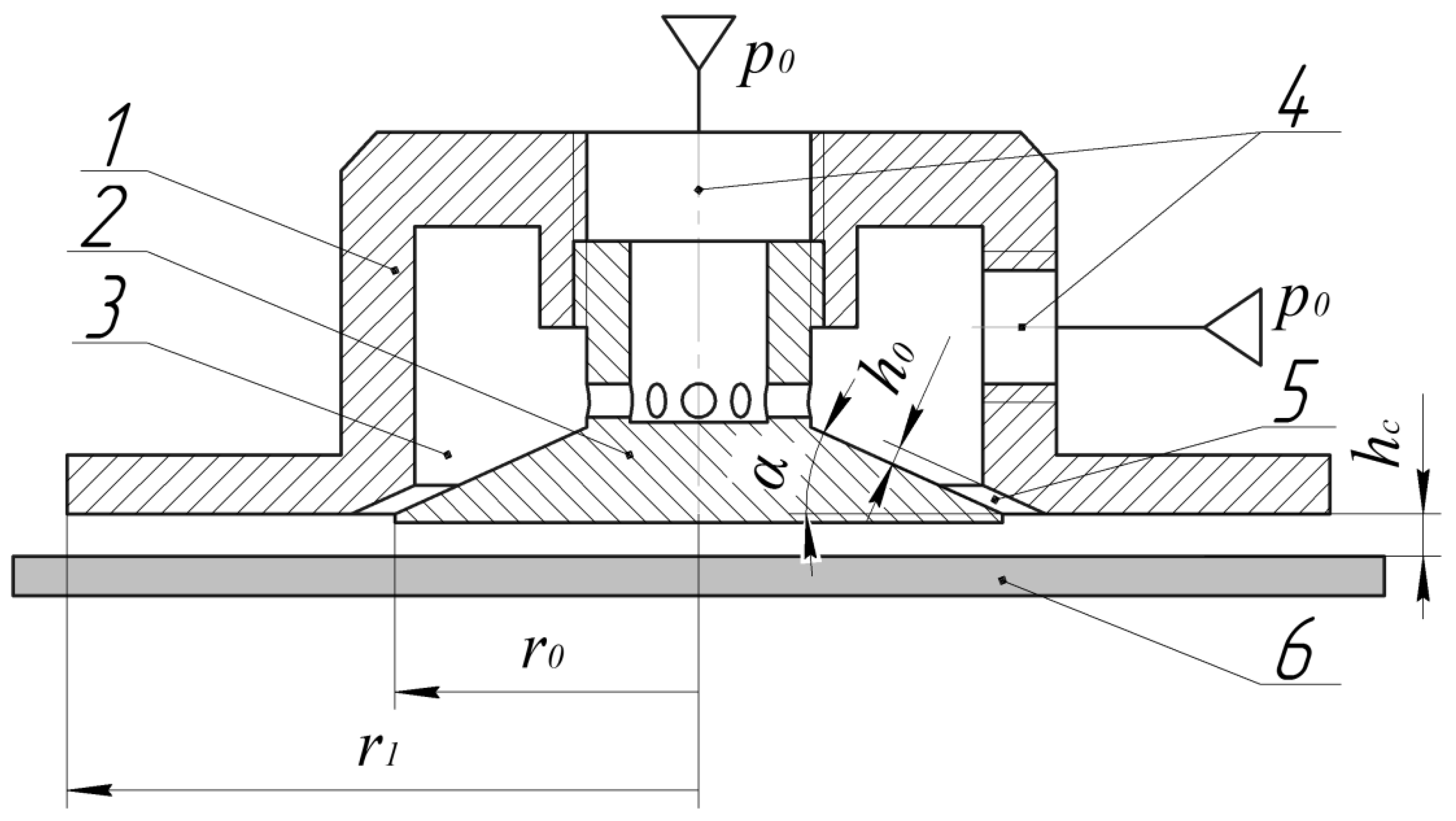
The operating principle and design of a Bernoulli gripper with an annular nozzle is shown in Figure 2. The main part of the Bernoulli gripping device, its body, is labeled as (1). In (1), a conical insert, labeled (2), is attached, forming with the inner surface of the body chamber (labeled (3)). Compressed air (p0) is supplied to (3) through the holes (labeled (4)). In addition, the conical insert, (2), forms with the body, (1), an annular nozzle (labeled (5)).
The annular air flow, which flows through the nozzle (5), and refracts to the surface of the manipulated object (OM) (6), between the body end and the object forms a flat radial flow. The high jet velocity at the outlet of the annular nozzle contributes to the ejection phenomenon; as a result, the absolute pressure p1 on the surface of the OM in the zone opposite the conical insert decreases to a value of less than the atmospheric pa. This results in an aerodynamic effect of attraction of the OM to the end of the grip. Special stops or friction elements [83] are prevented by the lateral displacement of the OM in its own plane.
Considering that the distribution of the absolute pressure pr on the surface of the OM is practically symmetrical to the axis of the BGD, it is possible to find the value of the lifting force [84], as follows:
F = F 1 + F 2 ,
F 1 = π r 0 2 ( p a p 1 ) ,
F 2 = 2 π r 0 r 1 ( p a p r ) r d r ,
where F1 and F2 are the forces caused by rarefaction in the interval between the interacting surfaces of the grip and the object, respectively, in the zone opposite the conical insert and the zone opposite the end of the body; pa = 0.1033 MPa is the pressure under normal conditions; p1 and pr are the absolute pressure values, respectively, in the area opposite the conical insert and at the radius r; r0 is the radius of the conical insert; and r1 is the radius of the gripper housing. A detailed description of the theoretical method is given in Appendix A. The key parameters with the most influence on the power and account characteristics of a BGD are the air pressure in camera 3, radius conical insert r0, outer radius of gripper r1, and distance of hc from the edge of the BGD to the OM.

2.2. Finite Element Method

The mathematical model of air in the radial interval between the interacting surfaces of the BGD and the OM is based on the Navier–Stokes (Reynolds-averaged Navier–Stokes equations) (RANS) equation’s average, according to Reynolds [84,85]. The SST model of turbulence [86,87,88] and the γ-model of laminar and turbulent transition [89] are used for modeling. The main equations for describing these models are presented below.
The gamma model of laminar and turbulent transition is described by one differential equation for the intermittency coefficient γ:
( ρ γ ) t + ( ρ V j γ ) x j = P γ E γ + x j [ ( μ + μ t σ γ ) γ x j ] ,
where ρ is the air density; t is the time; x is the coordinate; V is the vector of air velocity; Pγ and Fγ are, respectively, the generative and dissipation members of the managing directors of laminar and turbulent transition; μ is the molecular dynamic viscosity of gas; μt is the turbulent dynamic viscosity of gas; and σγ = 1.0 is the model constant.
The coupling between the transition model and the SST turbulence model is the same as for the γ-Reθ model [90], and it is accomplished by modifying the equations of the original SST model as follows:
t ( ρ k ) + x j ( ρ V j k ) = P ˜ k + P k lim D ˜ k + x j ( ( μ + σ k μ t ) k x j ) ,
t ( ρ ω ) + x j ( ρ V j ω ) = α P k v t D ω + C d ω + x j ( ( μ + σ ω μ t ) ω x j ) ,
P ˜ k = γ P k ,
D ˜ k = max ( γ , 0.1 ) · D k ,
μ t = p a 1 · k max ( a 1 · ω , F 2 · S ) ,
S i j = 1 2 ( V i x j + V j x i ) ;   S 2 = 2 S i j S i j ,
where k is the kinetic turbulent energy; ω is the specific speed of dissipation of the kinetic energy of turbulence; Pk and Dk, are, respectively, the original generation and dissipation of the SST model; P k lim is the additional part, which provides the correct gain of turbulent viscosity in the transitional area at a very low level of turbulent viscosity of the running stream; vt is the turbulent kinematic viscosity of gas; and σk, α, and α1 are, respectively, the empirical constants of the model.
The generative member in Equation (5) appears as follows:
P γ = F l e n g t h ρ S γ ( 1 γ ) F o n s e t ,
where Flength is the empirical correlation which controls the length of the transitional area (with Flength = 100) and Fonset is the function controlling the provision of the beginning of the transition.
The destruction/relaminarization source is identical to the one used in the γ-Reθ model [83] and is defined as follows:
E γ = c a 2 ρ Ω γ F t u r b ( c e 2 γ 1 ) ,
where ca2 = 0.06 and ce2 = 50 are the empirical constants, Ω = 2 Ω i , j Ω i , j is the invariant of the tensor of vorticity, and F t u r b = e ( R T 2 ) 4 ; R T = ρ k μ ω .
The formulation of the function Fonset is similar to that used in the γ-Reθ model. It is used to start the intermittency production (i.e., to activate the source value (11)). It contains the ratio of the Reynolds number to the local vortex ReV (in the current formulation, the strain rate is actually used within ReV, which is equivalent to the boundary layers) to the critical Reynolds number Reθc. However, Reθc is not calculated from the transport equation, and instead is calculated algebraically using k and other local variables. As a result, the beginning of the transition is controlled by the following functions:
F o n s e t 1 = Re v 2.2 Re θ c ,   Re v = ρ d ω 2 S μ ,
F o n s e t 2 = min ( F o n s e t 1 , 2.0 ) ,
F o n s e t 3 = max ( 1 ( R T 3.5 ) 3 , 0 ) ,
F o n s e t = max ( F o n s e t 2 F o n s e t 3 , 0 ) ,
where dω is the distance to the next wall.
The value of a critical Reynolds number of an impulse loss Reθc is calculated with the help of an algebraic ratio with use of local variables [91]:
Re θ c = f ( T U L , λ θ L ) .
The generation of Pk is counted by means of the Kato–Launder formula:
P k = μ t S Ω .
An additional production term, P k lim has been introduced into the k equation to ensure the proper generation of k at the transition points for arbitrary low (down to zero) TU levels. The need for such a term has the important reason that, for very low values of free flow turbulence, the underlying SST model itself requires a relatively long time to create turbulence within the boundary layer, even if it works properly with the transition model. The additional term is intended to be switched off when the transition process is completed and the boundary layer reaches a completely turbulent state. The expression for the P k lim is shown by:
P k lim = 5 C k max ( γ 0.2 , 0 ) ( 1 γ ) F o n lim max ( 3 C S E P μ μ t , 0 ) S Ω , C k = 1.0 , C S E P = 1.0 ;
F o n lim = min ( max ( Re V 2.2 · Re θ c lim 1 ,   0 ) , 3 ) ;   Re θ c lim = 1100 .

3. Results and Discussion

3.1. Influence of Compressed Air Supply Direction on BGD Power Characteristics

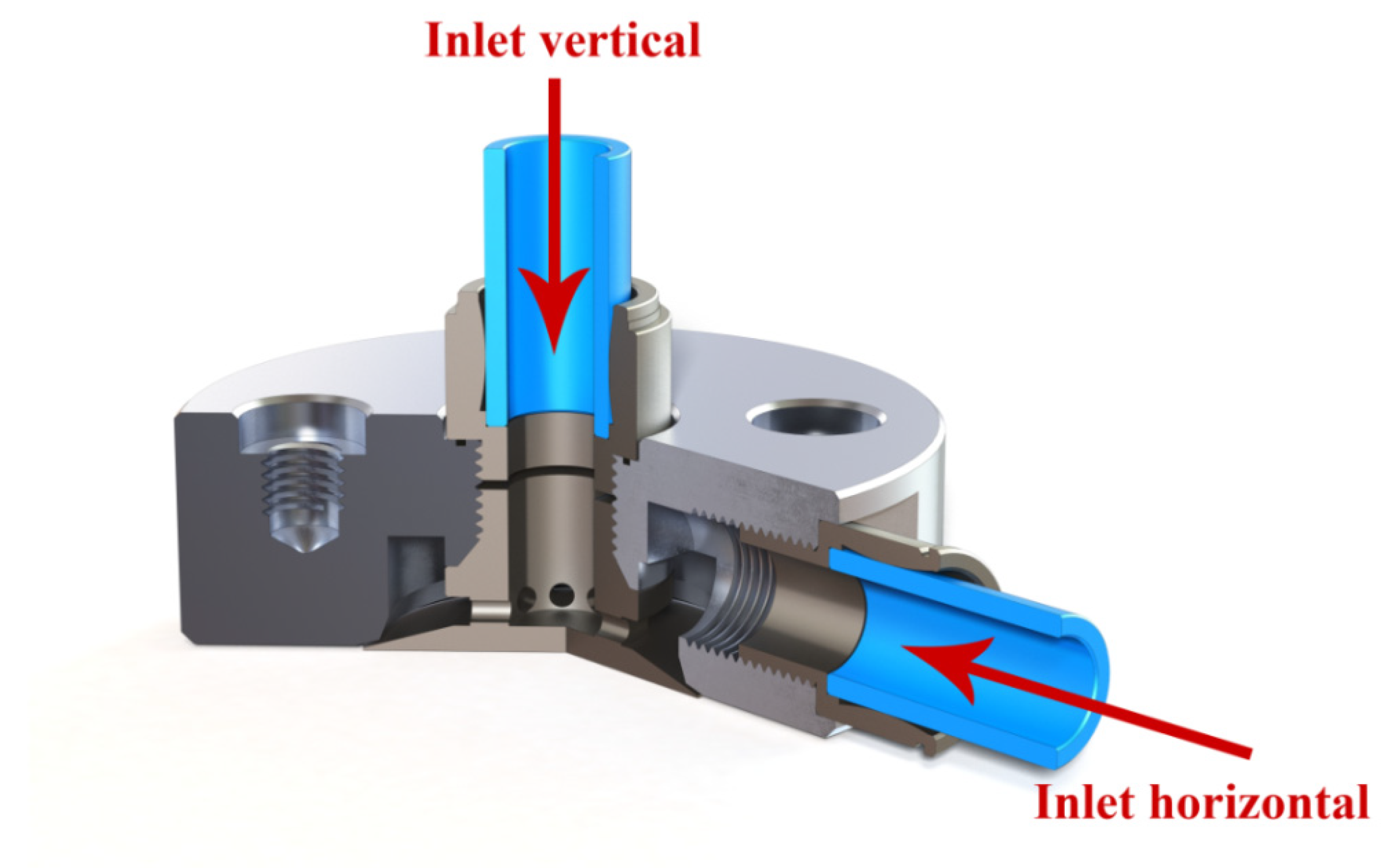
We considered the default design of Bernoulli gripping devices with an arc nozzle (Figure 3) for the subsequent study. In the default design, with a vertical supply, compressed air passes through a conical insert and, through radial holes, enters the chamber of the gripping device, and with a horizontal supply, the compressed air directly enters the chamber of the gripper through the body of the gripper.
In this study, we fixed certain parameters as constants: the radius of the gripping devices as r1 = 30 mm, the radius of the conical insert as r0 = 15 mm, the angle of the conical insert as α = 15 deg, the width of the nozzle as h0 = 0.06 mm, and the diameter of the inlet hole of the fittings as d = 8 mm.
We carried out numerical modelling in the environment of computing hydro- and gas-dynamics using Ansys-CFX with use of the SST of the γ-model of turbulence. To solve the problem of numerical modeling, final and differential grids were built in this software environment (Figure 4).
The total number of nodes in the design area depends on the outer grip radius r1 and the height of the gap between the manipulation object and the grip hc. In order to ensure the adequate operation of the SST model and to simulate wall air flows, it is necessary that the minimum number of elements between the walls of the model is three. Therefore, the number of nodes lies within 0.9–3 million and the number of elements lies between 4.5 and 12 million for the range of distances between the BGD and OM hc = 0.1 and 0.5 mm. The ideal gas from the program library is used during the simulation. The boundary conditions for two models of air flow are presented in Figure 5.
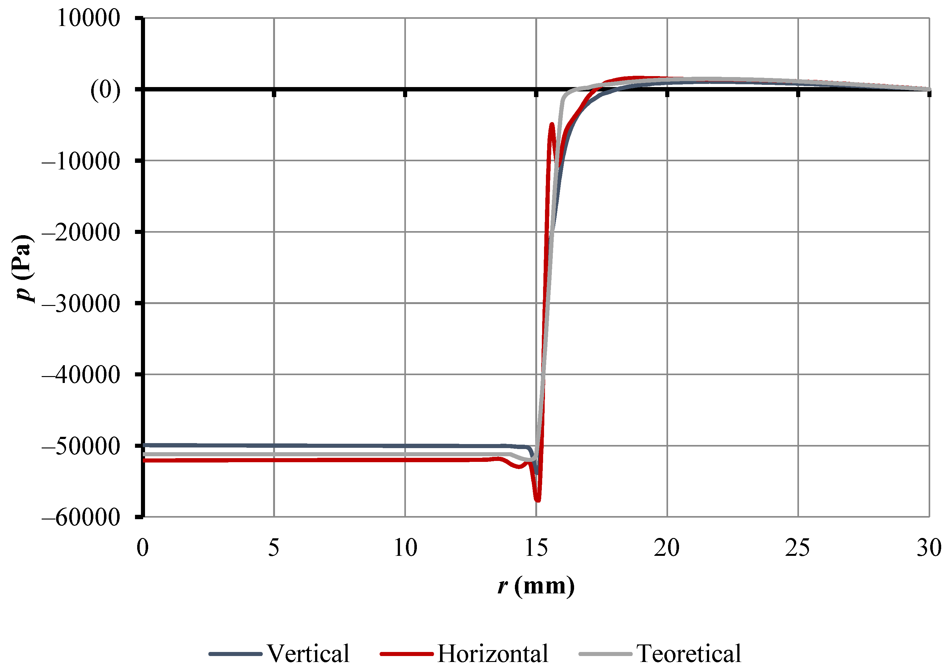
Using the SonicTurbFoam solver (for turbulent streams of the compressed gases moving with sound and supersonic speeds), one can obtain the value of the distribution of teak, speed, and force over the surfaces of the studied model. For further analysis of the obtained results of modeling and theoretical research, the results of the pressure distribution on the surface of the object manipulation are shown in Figure 6.
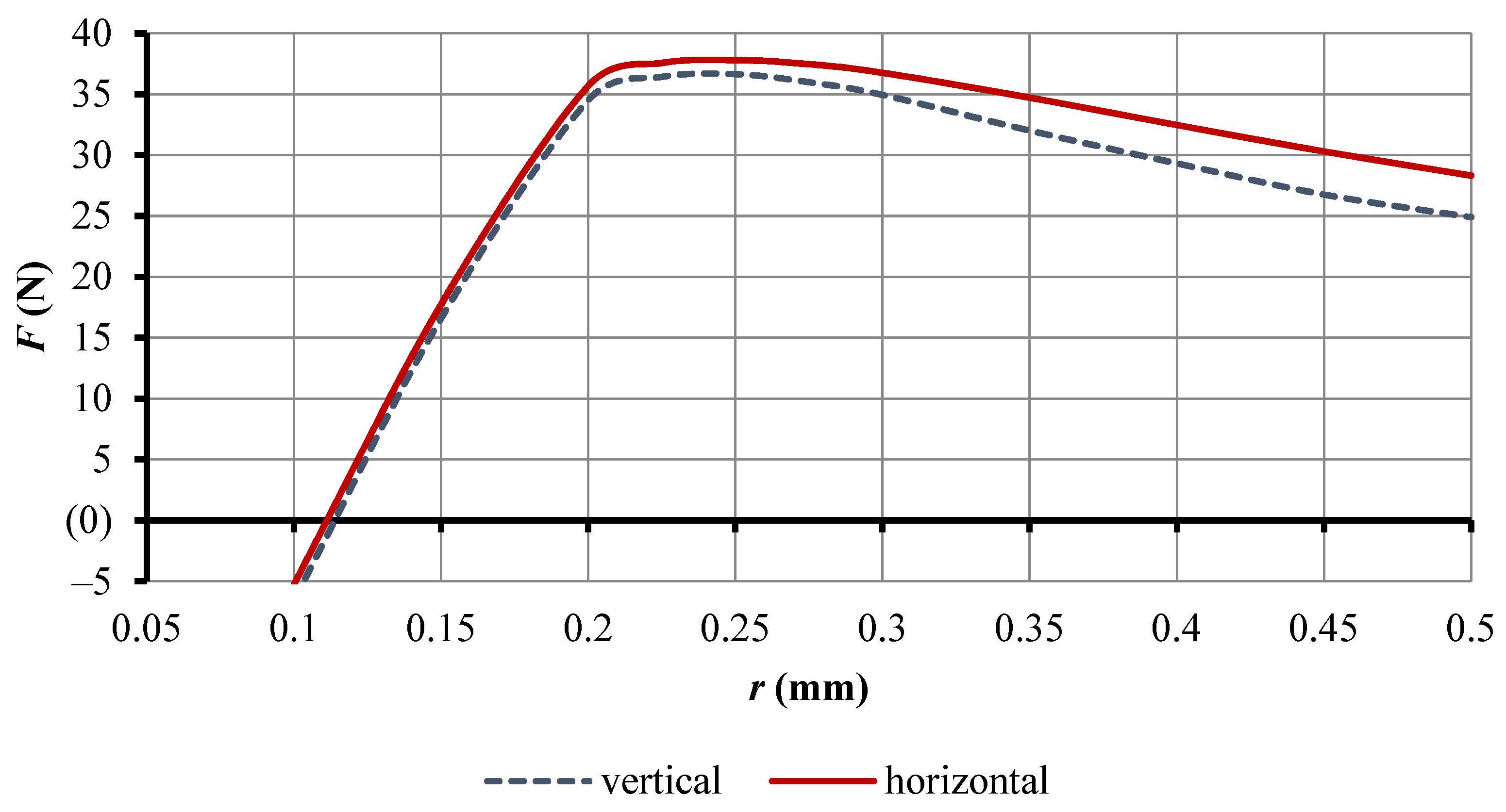
As seen in Figure 6, the vacuum in the area below the conical insert is greater for the horizontal pressure supply. The theoretical results of calculating the pressure distribution on the surface of the object under the conical insert are 2% less than the method obtained using the finite element (FEM), in which the gas-dynamic problems indicate their reliability. However, the mathematical model presented does not take into account the methods of supplying air to the chamber of the gripping devices, and so FEM in the Ansys-CFX software environment is later applied for research. In general, the Ansys-CFX tool has determined that the lifting force for a vertical supply of compressed air is 36.6 N and for horizontal, 37.7 N. To analyze the reason for the differences in lifting force in different directions of supply of compressed air, the pressure distribution along the plane of symmetry of the gripping device in Figure 7 is considered.
By observing the pressure distribution over the BGD symmetry plane, it is obvious that at in a vertical inlet (Figure 7a), the compressed air loses some of its energy in the act of leaking from the conical insert into the chamber of the gripping device. But, with a horizontal inlet (Figure 7b), the compressed air enters directly into the chamber of the gripping device and thereby provides more pressure inside. Due to the higher pressure in the chamber at the horizontal inlet, a greater dilution of the BGD is provided, which, at the given parameters of the system, increases the attraction force by 1.1 N. In order to conduct a more detailed analysis, the dependence of the lifting force of the BGD on the gap between the BGD and the OM is derived (Figure 8). To obtain the simulation results, changes were made in the height of the gap (hc) with a discreteness of 0.05 mm and in the zone hc = 0.2…0.3 mm with discreteness 0.025.
It can be seen from Figure 8 that the tendency continues to be that the lifting force at a vertical inlet is less than at a horizontal inlet. Furthermore, as the gap between the BGD and the OM increases, the decrease in force at a vertical inlet is clear and can reach up to 13%. This is because the compressed air flow through the annular nozzle of the BGD increases as the gap increases. To ensure a greater lifting force of the BGD, it can be concluded that it is advisable to use a horizontal inlet. In addition, with a horizontal inlet providing a greater lifting force at a greater gap between the BGD and the OM, it is possible to grip objects of manipulation from a greater distance. This characteristic is very significant since Bernoulli’s gripping devices are characterized by a very narrow range of gripping distance (0.2 to 2 mm), depending on the weight of the OM. For further studies of the effect of compressed air supply parameters on the power characteristics of a BGD, a horizontal inlet scheme will be used.

3.2. Impact of Internal Fitting Diameter on BGD Power Characteristics

Since one of the main parameters affecting the power characteristics of a Bernoulli gripping device is its flow characteristics (L/min) [91], the internal diameter of the fittings, which throttle flow, can affect this particular indicator. Therefore, to investigate the effect of the inner diameter of the fitting on the power characteristics of a BGD, the main threaded connections used in the manufacture of BGDs are defined as 1/8, 1/4, 3/8, 1/2, M5, and M7. Usually, collet pneumatic fittings, which are manufactured by various companies, are used to supply compressed air (Metal Work [92], Camozzi Automation [93], Festo [94], SMC [95] and others). For all the above-mentioned companies, the collet fittings have a similar structure (Figure 9) in the given range of threads, and it is possible to use different pipe thicknesses (4, 6, 8, 10, and 12 mm) with different flow sections.
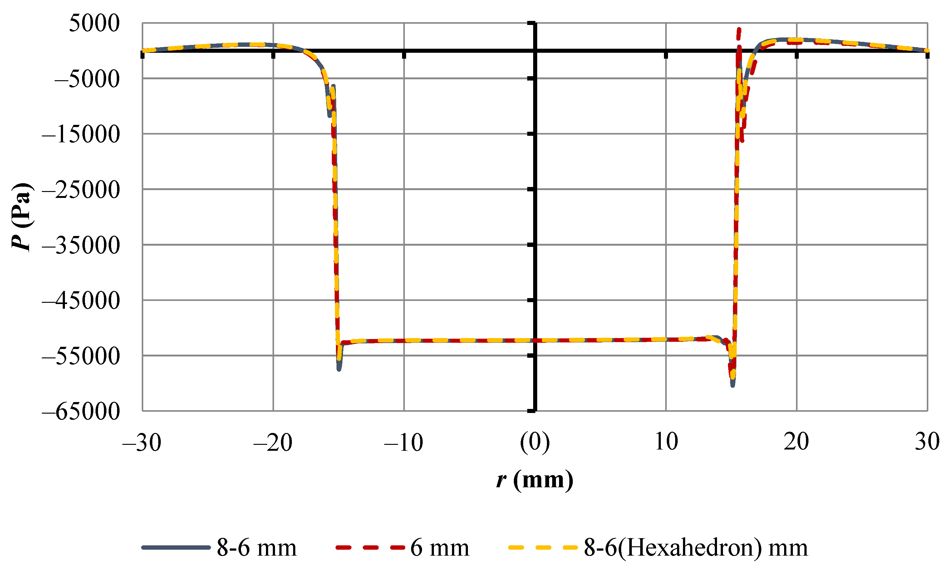
As can be seen from the design of collet fittings (Figure 9), the smallest diameter of the through section is located at the place of twisting the fitting with a hexagon (SW1 (Figure 9a), H (Figure 9b), 1 (Figure 9c), and CH 4 (Figure 9d)). For different fitting threads, the diameter of the taper varies (2.5, 4, 5, 6, 7, and 8 mm), and they have an average length of 5 mm. As this narrowing can lead to throttling of the stream of compressed air, research on the influence of the parameters of narrowing the fitting on the power characteristics of a Bernoulli gripping device is carried out. The gap between the BGD and the OM at hc = 0.25 mm ensures the maximum lifting force, with the system parameters r1 = 30 mm, r0 = 15 mm, α = 15 deg, and h0 = 0.06 mm. To begin with, the influence of the input geometry on the power characteristics of a BGD is considered as follows: narrowing the fitting with a round diameter of 6 mm and a length of 5 mm, narrowing the fitting with a transition from 8 to 6 mm with a length of 5 mm, and narrowing the fitting with a transition from 8 to a hexagon with a diameter of 6 mm and a length of 5 mm (Figure 10).
From the graph shown in Figure 10, it is clear that the pressure distribution on the surface of the object of manipulation changes only in the range of 13 to 18 mm on the supply side of compressed air (Figure 11).
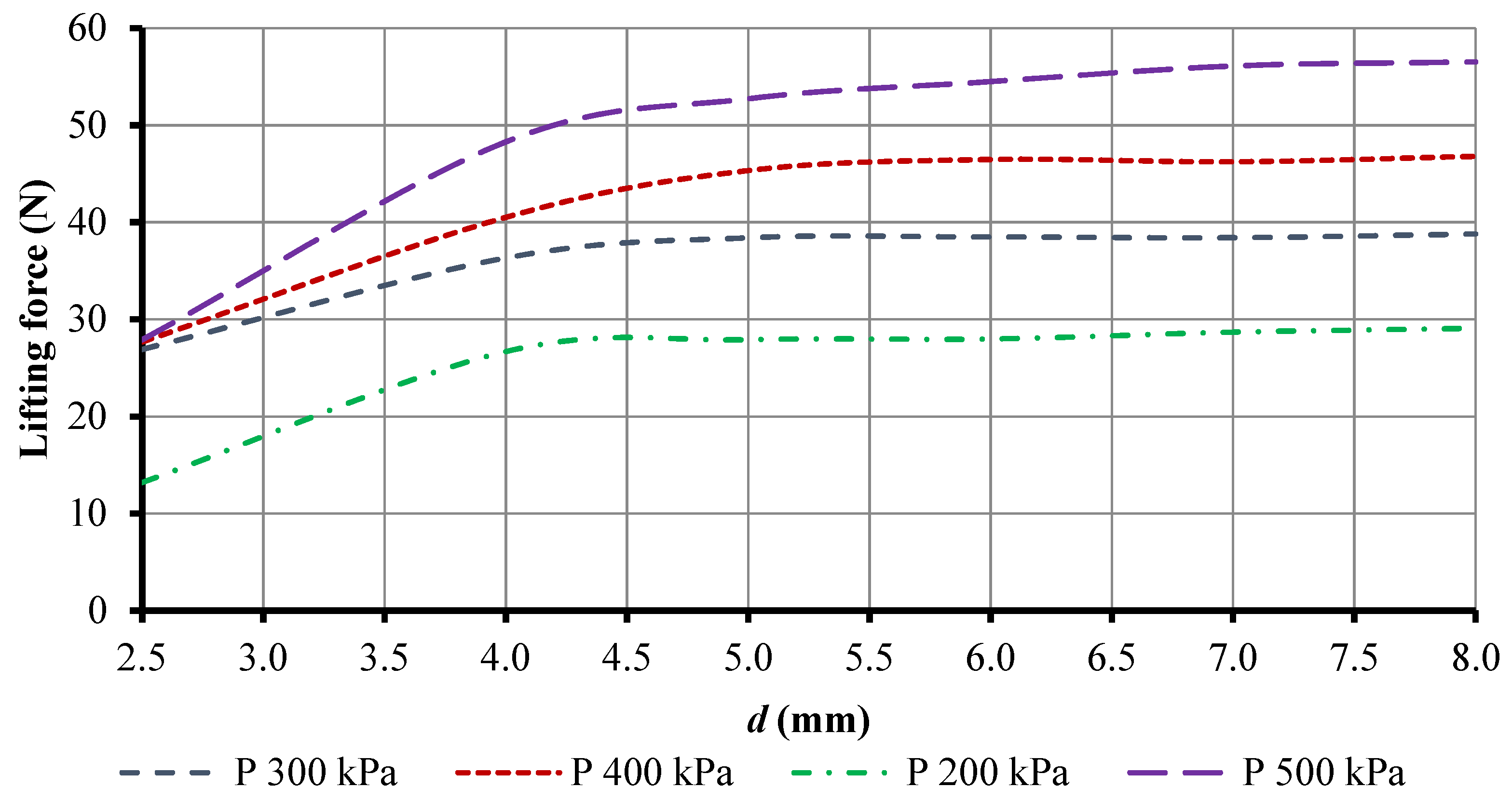
The pressure jump on the surface of an OM (Figure 11) is presented at a radius of 15.5 mm due to an uneven supply of compressed air to the gripping device chamber. The lifting force of a BGD for narrowing the fitting of a round diameter of 6mm results in 38.2892 N; for narrowing the fitting with a transition from 8 to 6 mm, it results in 38.281 N; and for narrowing the fitting with a transition from 8 to a hexagon with a diameter of 6 mm, it results in 38.2388 N. The difference in the lifting force of a BGD, which is dependent on the geometry of the narrowing of the fitting, is due to this jump in front of the nozzle on the supply side of compressed air. However, the difference in the lifting force for the narrowing in the form of a hexagon and a circle with a radius of 6 mm is 0.05 N, which can be neglected, and further research was done for a fitting with a narrowing of the cylindrical inlet from 8 mm to d. Subsequently, we conducted a study of the effect of a diameter of d (2.5, 4, 5, 6, 7, or 8) mm narrowing of the fitting (with a horizontal inlet) for the supply of compressed air into the chamber of the gripping device at different inlet pressures (Figure 12).
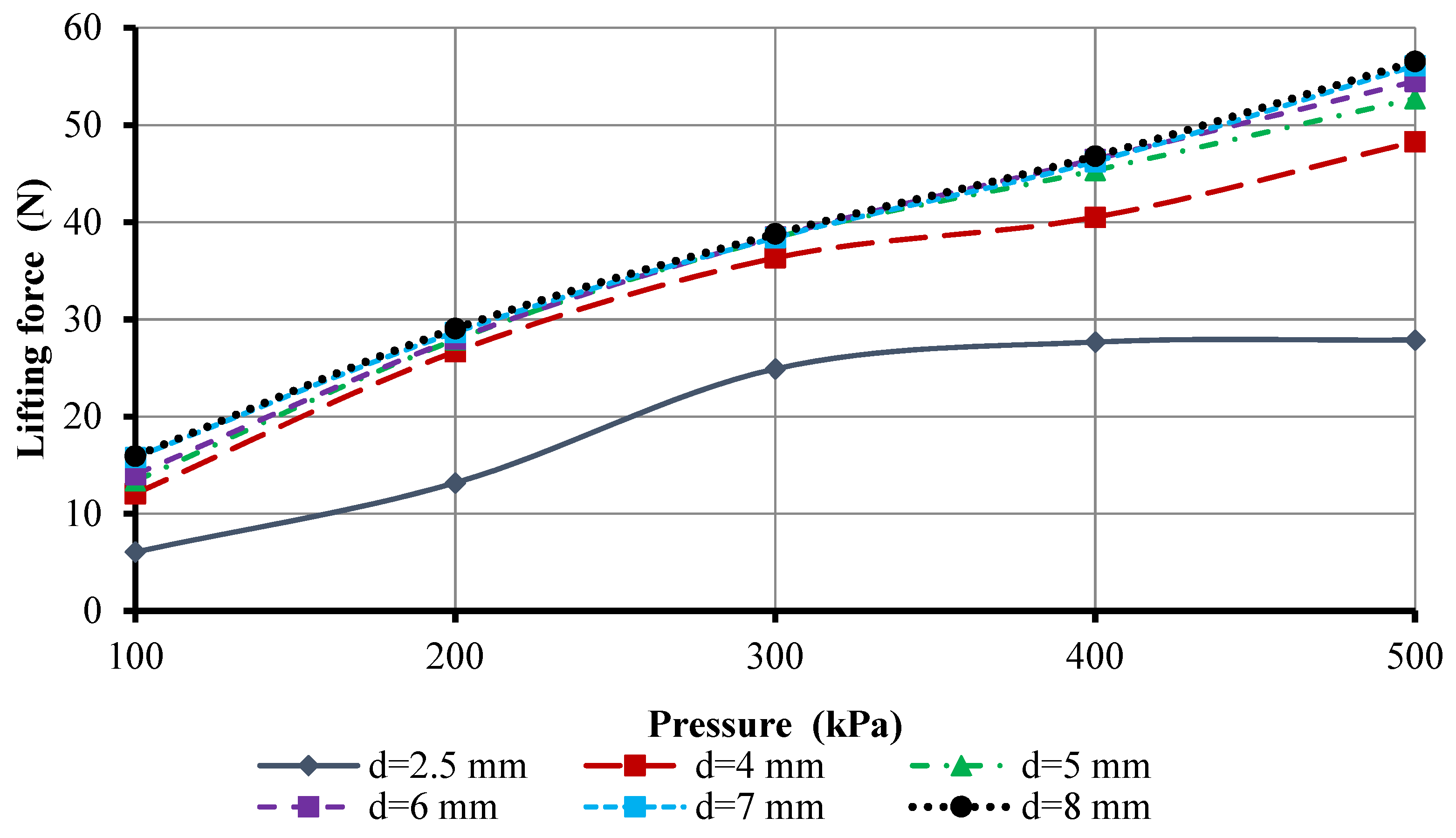
As shown in Figure 12, as the inlet diameter of the fitting d decreases, the incoming air flow is throttled, the compressed air flow rate of the gripping devices is limited, and the lifting force can be reduced to 55% at d = 2.5 mm (200 kPa, Figure 12). Therefore, depending on the lifting force resulting from the pressure, which is the main technical characteristic of the gripping device, the diameter of the contraction of the compressed air supply fittings will have a critical effect, and for the above gripping parameters, it will have the form seen in Figure 13.
After analyzing Figure 13, it can be concluded that as the diameter of the hole in the fittings increases, the power characteristics of a BGD will increase at all supply pressures. In particular, for a BGD with the parameters given earlier (d > 6 mm), the lifting force remains almost unchanged. This is due to the stable parameters of the maximum compressed air flow, which are characterized by the parameters of the nozzle elements and the height of the OM content. Therefore, for diameters, when the constriction of fittings d > 6 mm, the change in the compressed air flow rate over the entire range of the change in the supplied air pressure does not exceed 2%. For a comprehensive study of the influence of consumption and power characteristics, it is proposed to use the so-called C-factor [22]. As defined in [96], the C-factor of a gripper can be computed as the ratio of the force it produces over its weight, multiplied by the stroke. The value obtained is arguably a measure of the efficiency of the gripper, and it can be used for comparison between different products, designs, etc. Therefore, the calculation of the effect of supply pressure on the cost characteristics of a Bernoulli gripping device for lifting one kilogram of payload is as seen in (Figure 14).
Figure 14 shows that it is rational to use fittings with an internal diameter of d = 5 to 6 mm at a supply pressure of 200 to 300 kPa, and d = 7 to 8 mm at a supply pressure of 100 and 400 to 500 kPa. In particular, it should be noted that it is recommended to use several grips for lifting a manipulation object weighing more than 5 kg at lower power pressures. This will make it possible to evenly distribute the load on the object of manipulation and minimize the energy costs for the maintenance of the object. The same statement applies to objects with large overall dimensions. The use of several gripping devices will reduce possible deformations of the object and inertial loads during reorientation of the object. The flow rate of the gripping device also depends on the radius of the conical insert, which forms the length and total area of the circular nozzle member of the gripping device.
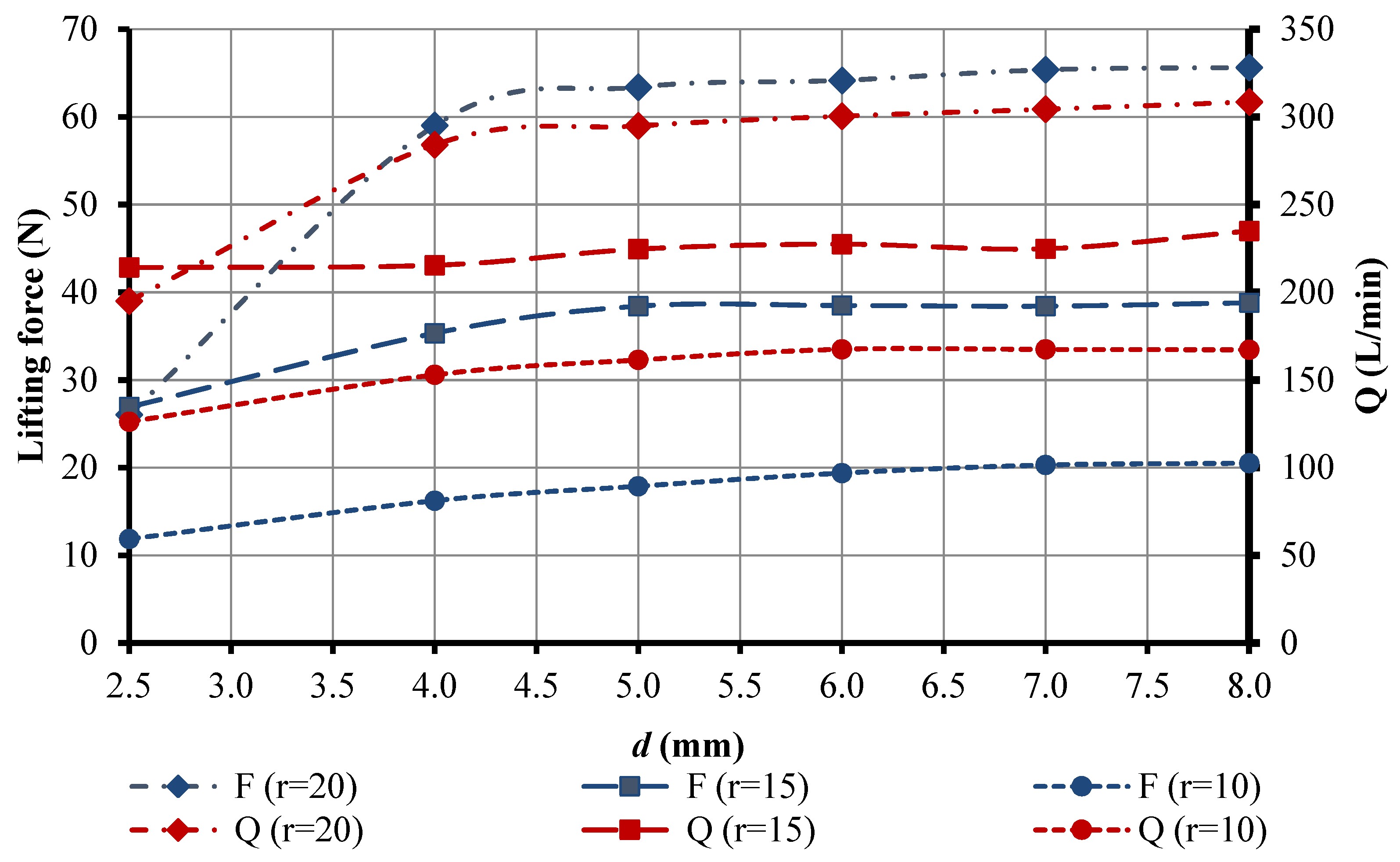
The impact of fittings tapering on a BGD’s flow and power characteristics at different radius of conical insertion of gripping devices r0 has been investigated (Figure 15). The height of the OH’s hc maintenance in such gripping devices is selected according to the maximum lifting force. For the entire range of BGDs with an annular nozzle which lies in the range of 0.2 to 0.3 mm, further studies are carried out with hc = 0.25 mm and at an inlet pressure of 300 kPa.
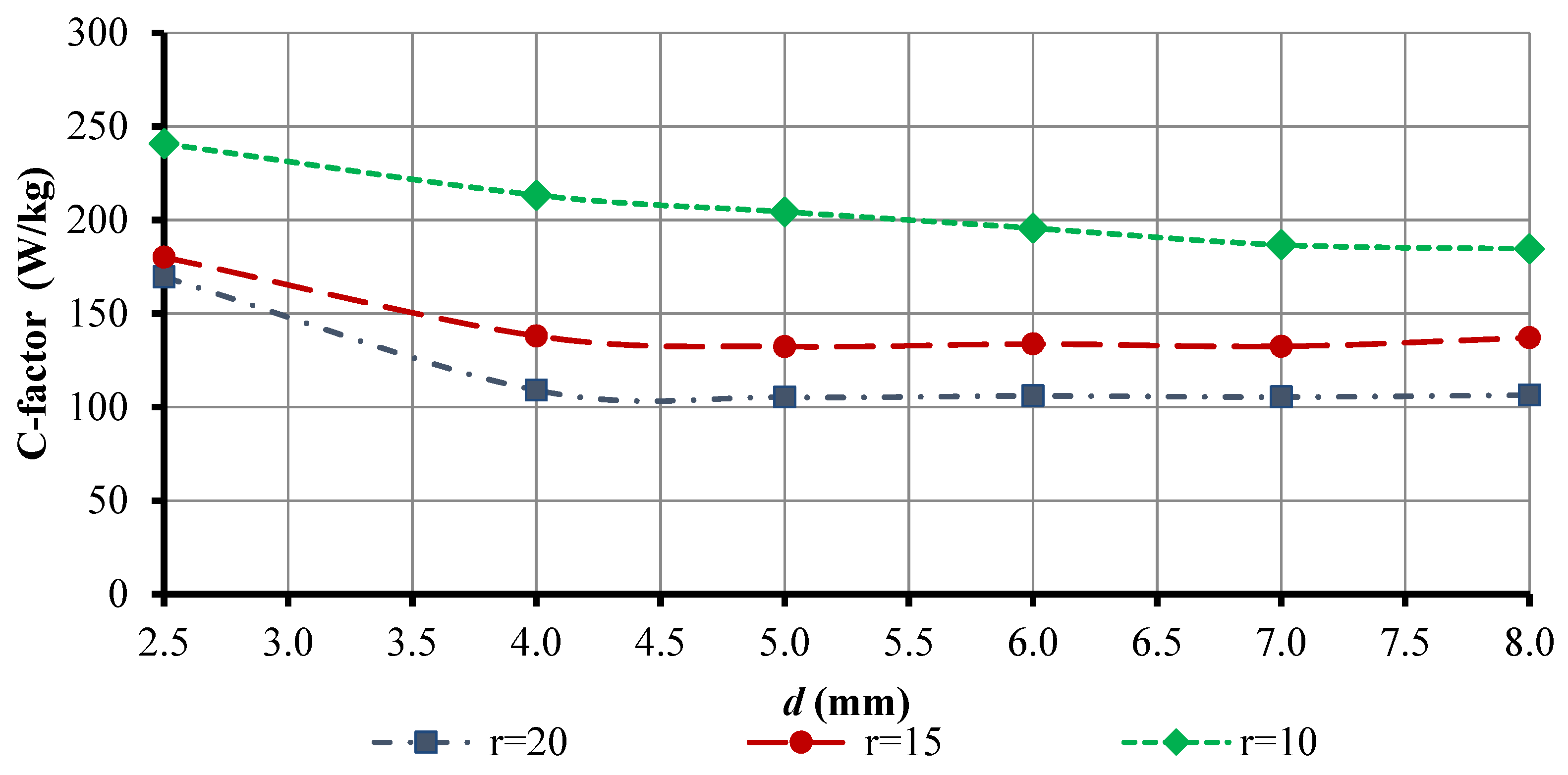
Comparing the grippers with different radii of the conical insert and the effect of fitting constriction diameter on BGD (Figure 15), it can be said that the consumption characteristics are clearly correlated with the power characteristics. In particular, it has been found that as the diameter of fitting constriction increases, the lifting force and flow rate increase throughout the study area. However, in the range of d = 6 to 8 mm, the lifting force remains practically not variable with the increase in compressed air flow rate for r0 = 15 and 20 mm, and at r0 = 10 mm, the lifting force increases uniformly with increasing flow rate. Therefore, for r0 = 10 mm, it is advisable to use the maximum diameter of the fitting constriction. The C-factor (Figure 16) is used for a detailed analysis of the effect of fittings on the energy characteristics of the grip at different radii of the conical insert.
From Figure 16, it is obvious that the gripper with a radius of conical insert r0 = 20 mm is the most effective. It provides a lifting capacity of one kilogram at a supply pressure of 300 kPa, the diameter of the narrowing of the fitting is d = 5 to 7 mm, and it consumes only 105 W. This is 25% less than a gripper with a radius of its conical insert of r0 = 15 mm. In addition, it should be noted that less energy is spent for r0 = 15 and 20 mm at d = 5 to 7 mm, and for r0 = 10 mm, it is less at d = 8 mm. This is due to the fact that with a small radius of the conical insert, r0 = 10 mm, and a large grip radius, r1 = 30 mm, much more air flow energy is used to overcome the friction forces of the air flow arising at the radii from r0 to r1.

4. Conclusions

The paper presents the results of theoretical studies and uses the finite element method for determining the distribution of pressure on the surface of an object of manipulation, which allow one to determine the lifting force of a Bernoulli gripping devices, as follows:
  • For the most common designs of air supply to the chamber of the gripping device, which are perpendicular to the fastening of gripping and horizontal to the fastening, finite element modeling in CFD was carried out. The adequacy of the obtained research results from the use the finite element method, namely, to the deviation of the theoretical results, which does not exceed 2%. It was determined that the theoretical method of research allows for the determination that only the influence of air pressure during air supply to the gripping device chamber affects its power characteristics. Therefore, it was further determined by the CFD finite element method that horizontal air supply to the gripping chamber should be used to provide the maximum possible lifting force. The constructed characteristic of the effect of the manipulation object gripping distance on its lifting force applies to both air supply structures.
  • Structures and constriction in fittings are considered, which are used to supply compressed air to the chambers of Bernoulli gripping devices. Dependencies of the type of influence of the fittings narrowing on the power characteristics of the gripping devices are displayed. It was revealed that the difference in the lifting force of a Bernoulli gripping device that depends on the geometry of the fitting constriction is due to the pressure jump opposite the nozzle from the side of the compressed air supply, and for a supply pressure of 300 kPa, it affects the attraction force by only 0.05 N. Therefore, the design of the fittings from 8 mm to the diameter of the constriction was chosen in further studies.
  • For the most common diameters, the constrictions of the fittings at 2.5, 4, 5, 6, 7, and 8 mm shows the distribution of the lifting force at different supply pressures. It has been found that when the inlet diameter of the fitting decreases, the inlet air flow is throttled, which limits the compressed air flow rate of the gripping device and can reduce the lifting force by 55%. For a comprehensive study of the impact of consumption and power characteristics, the C-factor was used, and it was established that it is rational to use fittings with an internal diameter of 5 to 6 mm at a supply pressure of 200 to 300 kPa, and for 7 to 8 mm, a supply pressure of 100 and 400 to 500 kPa is used.
  • It was revealed that the flow characteristics clearly correlate with the power characteristics at a different radius of the conical grip insert. In particular, it has been found that as the diameter of fitting constriction increases, the lifting force and flow rate increase throughout the study area. However, in the range of the inside diameter of the fitting of 6 to 8 mm, the lifting force remains practically unchanged with an increase in the flow rate of compressed air for the radii of the conical insert of the grip of 15 and 20 mm, and with a radius of the conical insert of the grip of 10 mm, the lifting force increases uniformly with increasing flow rate. To study the most effective radius of a conical insert, the C-factor was output at various input parameters, according to which, it was determined that the grip with a radius of the conical insert of 20 mm spends less energy to lift one kilogram of net weight. To provide a load capacity of one kilogram at a supply pressure of 300 kPa, a diameter of the fitting constriction of 5 to 7 mm for a Bernoulli gripping device uses an average of 105 W.
In future work, it is planned to consider the influence of the input parameters of a Bernoulli gripping device’s handling system on rigid and non-rigid objects of manipulation, with the intent to develop a new gripping design for porous and flexible objects.

Author Contributions

Conceptualization, R.M. and J.X.; methodology, R.M.; software, R.M.; formal analysis, R.M.; investigation, R.M.; resources, J.X.; writing—original draft preparation, R.M.; writing—review and editing, J.X.; visualization, R.M.; project administration, J.X.; funding acquisition, R.M. All authors have read and agreed to the published version of the manuscript.

Funding

This work was supported in part by the U.S. Department of State (DOS), Bureau of Educational and Cultural Affairs (ECA), Exchange Visitor Program #G-1-00005 with the cooperation of the Institute of International Education (IIE) under Fulbright Grant PS00322778.

Institutional Review Board Statement

Not applicable.

Informed Consent Statement

Not applicable.

Acknowledgments

Roman Mykhailyshyn would like to thank the Fulbright Program, which turns 75 this year, and Jing Xiao for the opportunity to conduct research in the United States.

Conflicts of Interest

The authors declare no conflict of interest.

Appendix A

To determine the nature of the pressure distribution pr in the radial gap, the Bernoulli equation is written for radii r and r1 [6] as follows:
p r ρ a m + V r 2 2 = p a m ρ a m + V 1 2 2 + E r r 1 ,
where Vr and V1 are the air flow rates at radii r and r1, respectively, and Err1 is the loss of specific energy of the flow at the interval from r to r1.
The elemental losses of a specific energy of dE flow on the elemental segment dr are found by the known dependence [76]:
d E = λ m V r 2 2 d r D g ,
where λm is the coefficient of the viscous friction of the air to the active surface of the grip and the object of manipulation, which depends on the Reynolds number and surface roughness, and Dg = 2hr is the hydraulic flow diameter at the radius r.
The coefficient of viscous friction λ for the turbulent air movement mode is conveniently calculated by empirical formula [76]:
λ = 0.11 K n ( Δ D g + 68 Re ) 0.25 ,
where Kn is a coefficient that takes into account the non-circular cross-section of the flow (for an annular section of Kn = 1.1) [48]; Δ is the equivalent absolute roughness of the surfaces of the flow-forming air, which can be taken as equal to the roughness along Ra of the surface of the manipulated object; and Re is the Reynolds number. The Reynolds number Re for streams of any form is determined with [53]:
Re = ρ V D g μ d ,
where μd = 1.71·10−5 + 4.94·10−8t is the coefficient of the dynamic viscosity of air (kg/(s·m)) and t is the ambient temperature (°C).
Given the mass flow of air in the radial annular interval G = Vrρa2πh, we obtain:
Re = G π μ d r ,   λ = 0.121 ( Δ 2 h + 68 π μ d r G ) 0.25 .
According to the velocity flow continuity equation,
V r = G 2 π ρ a r h ,     V 1 = G 2 π ρ a r ( h + δ ) .
We will find the total losses of the specific energy of the flow by integrating Equation (A2) and considering (A3) and (A4):
E r r 1 = 1 16 π 2 G 2 ρ a 2 r r 1 0.121 ( Δ 2 h + 68 π μ d r G ) 0.25 h 3 r 2 d r .
Substituting the result in (A1), after the transformations, the following is obtained:
p r = p a G 2 8 π 2 ρ a [ 1 h 2 r 2 1 ( h + δ ) 2 r 1 2 1 2 r r 1 0.121 ( Δ 2 h + 68 π μ r G ) 0.25 h 3 r 2 d r ] .
In order to determine absolute pressure p1 at the end of the gripping, we must conduct a gas-dynamic analysis of the process of the air flow outflow from the annular nozzle and its expansion in the radial interval h to the radius r1. To do this, we compose the equation of pulses of forces in projections on the x-axis for the selected element dϕ of the radial gap h:
d G V 0 cos ϕ + p 1 h r 0 d ϕ cos ϕ + 2 h r 0 r 1 p d r sin d ϕ 2 cos ϕ + + 2 h r 0 r 1 p r d r sin d ϕ 2 cos ϕ = d G V 1 cos ϕ + p r 1 h r 1 d ϕ cos ϕ + d F f .
where dG = V0ρ0hr0 is the elementary mass flow of air through the annular nozzle and dFf is the elemental force of the viscous friction of air flow in the end surfaces of the grip and the object.
The differential of the second order from the frictional force d2Ff is defined as the double product of the friction stress τr on the elementary area dS = dr·r·dϕ. In the x projection:
d 2 F f = 2 τ r r d r d ϕ cos ϕ .
The friction stress at the radius r can be calculated by the formula:
τ r = ρ a V r 2 8 λ m .
Assuming that the coefficient of the viscous friction at the interval from r0 to r1 is stable and equal to the average value,
λ m = 0.121 ( Δ 2 h + 34 π μ d ( r 0 + r 1 ) G ) 0.25 ,
integrating (A10), we obtain:
d F f = λ m 4 V 0 2 ρ 0 2 r 0 2 ρ a cos ϕ d ϕ r 0 r 1 d r r = λ m 2 V 0 2 ρ 0 2 r 0 2 ρ a ln r 1 r 0 cos ϕ d ϕ .
Having integrated (A6) in the range from r0 to r1, and given G = 2πV0ρ0r0h, after the transformations, we find:
r 0 r 1 p r d r = p r 1 ( r 1 r 0 ) + V 0 2 ρ 0 2 r 0 2 2 ρ a [ r 1 r 0 r 1 2 + 1 r 1 1 r 0 + λ m 2 h ( ln r 1 r 0 r 1 r 0 r 1 ) ] .
Substituting (A13) and (A15) into (A9), and considering that with the small dϕsin(/2) = /2, we obtain the equation:
V 0 2 ρ 0 [ r 0 h ρ 0 r 0 2 h 2 ρ a ( r 0 2 + r 1 2 r 1 2 r 0 + λ m 2 h r 1 r 0 r 1 ) ] = ( p r 1 p 1 ) r 0 h .
Using the SaintVenant equation and considering that for the adiabate process, p/ρk = const, after the transformations, we get:
2 k ϕ 2 k 1 ( p 0 k 1 k p 1 1 k p 1 ) [ r 0 h ρ 0 r 0 2 h 2 2 ρ a r 1 h ( r 0 r 1 + r 1 r 0 + λ m ( r 1 r 0 ) 2 h ) ] = ( p r 1 p 1 ) r 0 h .
Assuming that ρ0/ρa ≈ 1, the equation for determining p1 is as follows:
[ ( ( p r 1 p 1 ) ( k 1 ) 2 k ϕ 2 [ 1 r 0 2 r 1 ( r 0 r 1 + r 1 r 0 + λ m ( r 1 r 0 ) 2 h ) ] + p 1 ) p 1 1 k ] k k 1 = p 0 .

References

  1. McKerrow, P.J.; McKerrow, P. Introduction to Robotics; Addison-Wesley: Sydney, Australia, 1991; Volume 3. [Google Scholar]
  2. Nof, S.Y. (Ed.) Handbook of Industrial Robotics; John Wiley & Sons: Hoboken, NJ, USA, 1999. [Google Scholar]
  3. Garcia, E.; Jimenez, M.A.; De Santos, P.G.; Armada, M. The evolution of robotics research. IEEE Robot. Autom. Mag. 2007, 14, 90–103. [Google Scholar] [CrossRef]
  4. Siciliano, B.; Sciavicco, L.; Villani, L.; Oriolo, G. Robotics: Modelling, Planning and Control; Springer Science & Business Media: Berlin/Heidelberg, Germany, 2010. [Google Scholar]
  5. Siciliano, B.; Khatib, O. Springer Handbook of Robotics; Springer: Berlin/Heidelberg, Germany, 2016. [Google Scholar]
  6. Hägele, M.; Nilsson, K.; Pires, J.N.; Bischoff, R. Industrial Robotics. In Springer Handbook of Robotics; Springer: Cham, Switzerland, 2016; pp. 1385–1422. [Google Scholar]
  7. Lynch, K.M.; Frank, C.P. Modern Robotics; Cambridge University Press: Cambridge, UK, 2017. [Google Scholar]
  8. Kurfess, T.R. (Ed.) Robotics and Automation Handbook; CRC Press: Boca Raton, FL, USA, 2018. [Google Scholar]
  9. Chan, F.T.S.; Ip, R.W.L.; Lau, H. Integration of expert system with analytic hierarchy process for the design of material handling equipment selection system. J. Mater. Process. Technol. 2001, 116, 137–145. [Google Scholar] [CrossRef]
  10. Kaya, O.; Tağlıoğlu, G.B.; Ertuğrul, Ş. The Series Elastic Gripper Design, Object Detection, and Recognition by Touch. ASMEJ. Mech. Robot. 2022, 14, 014501. [Google Scholar] [CrossRef]
  11. Yi, J.; Yumbla, F.; Auh, E.; Abayebas, M.; Luong, T.A.; Moon, H. Passive Aligning of Ribbon Cable in Sliding Surface Gripper for Assembly Task. ASMEJ. Mech. Robot. 2021, 13, 025001. [Google Scholar] [CrossRef]
  12. Henrich, D.; Wörn, H. Robot Manipulation of Deformable Objects; Springer Science & Business Media: Berlin/Heidelberg, Germany, 2012. [Google Scholar]
  13. Zoghlami, F.; Kurrek, P.; Jocas, M.; Masala, G.; Salehi, V. Design of a Deep Post Gripping Perception Framework for Industrial Robots. ASMEJ. Comput. Inf. Sci. Eng. 2021, 21, 021003. [Google Scholar] [CrossRef]
  14. Jin, L.; Duan, X.; Li, C.; Shi, Q.; Wen, H.; Wang, J.; Li, H. Design of a Novel Parallel Mechanism for Haptic Device. ASMEJ. Mech. Robot. 2021, 13, 045001. [Google Scholar] [CrossRef]
  15. Koustoumpardis, P.N.; Aspragathos, N.A. A review of gripping devices for fabric handling. In Proceedings of the International Conference on Intelligent Manipulation and Grasping IMG04, Genova, Italy, 1–2 July 2004. [Google Scholar]
  16. Zhang, M.T.; Goldberg, K. A Computer-Aided Design Tool in Java for Planar Gripper Design. J. Comput. Inf. Sci. Eng. 2004, 4, 43–48. [Google Scholar] [CrossRef]
  17. Martell, M.J.; Díaz, J.; Schultz, J.A. A Linear Multiport Network Approach for Elastically Coupled Underactuated Grippers. J. Mech. Robot. 2017, 9, 51012. [Google Scholar] [CrossRef]
  18. Reddy, P.V.P.; Suresh, V.V.N.S. A review on importance of universal gripper in industrial robot applications. Int. J. Mech. Eng. Robot. Res. 2013, 2, 255–264. [Google Scholar]
  19. Kumbla, N.B.; Thakar, S.; Kaipa, K.N.; Marvel, J.; Gupta, S.K. Handling Perception Uncertainty in Simulation-Based Singulation Planning for Robotic Bin Picking. ASMEJ. Comput. Inf. Sci. Eng. 2018, 18, 021004. [Google Scholar] [CrossRef]
  20. Suresh, S.A.; Christensen, D.L.; Hawkes, E.W.; Cutkosky, M. Surface and Shape Deposition Manufacturing for the Fabrication of a Curved Surface Gripper. ASMEJ. Mech. Robot. 2015, 7, 021005. [Google Scholar] [CrossRef]
  21. Long, Z.; Jiang, Q.; Shuai, T.; Wen, F.; Liang, C. A Systematic Review and Meta-analysis of Robotic Gripper. IOP Conf. Ser. Mater. Sci. Eng. 2020, 782, 042055. [Google Scholar] [CrossRef]
  22. Birglen, L.; Schlicht, T. A statistical review of industrial robotic grippers. Robot. Comput.-Integr. Manuf. 2018, 49, 88–97. [Google Scholar] [CrossRef]
  23. Mikolajczyk, T. Indication of Machining Area with the Robot’s Camera using. Appl. Mech. Mater. 2013, 282, 146–151. [Google Scholar] [CrossRef]
  24. Gao, Y.; Huang, X.; Mann, I.S.; Su, H. A Novel Variable Stiffness Compliant Robotic Gripper Based on Layer Jamming. ASMEJ. Mech. Robot. 2020, 12, 051013. [Google Scholar] [CrossRef]
  25. Bogue, R. Artificial muscles and soft gripping: A review of technologies and applications. Ind. Robot. Int. J. 2012, 39, 535–540. [Google Scholar] [CrossRef]
  26. Boubekri, N.; Chakraborty, P. Robotic grasping: Gripper designs, control methods and grasp configurations–a review of research. Integr. Manuf. Syst. 2002, 13, 520–531. [Google Scholar] [CrossRef]
  27. Milojević, A.; Linß, S.; Ćojbašić, Ž.; Handroos, H. A Novel Simple, Adaptive, and Versatile Soft-Robotic Compliant Two-Finger Gripper With an Inherently Gentle Touch. ASMEJ. Mech. Robot. 2021, 13, 011015. [Google Scholar] [CrossRef]
  28. Chen, F.Y. Gripping mechanisms for industrial robots. In Robot Grippers; Springer: Berlin/Heidelberg, Germany, 1986; pp. 3–26. [Google Scholar] [CrossRef]
  29. Fantoni, G.; Santochi, M.; Dini, G.; Tracht, K.; Scholz-Reiter, B.; Fleischer, J.; Lien, T.K.; Seliger, G.; Reinhart, G.; Franke, J.; et al. Grasping devices and methods in automated production processes. CIRP Ann.-Manuf. Technol. 2014, 63, 679–701. [Google Scholar] [CrossRef]
  30. Raval, S.; Patel, B. A Review On Grasping Principle and Robotic Grippers. Int. J. Eng. Dev. Res. 2016, 4, 483–490. [Google Scholar]
  31. Lien, T.K. Gripper technologies for food industry robots. In Robotics and Automation in the Food Industry; Wood Head Publishing Limited: Sawston, UK, 2013; pp. 143–170. [Google Scholar] [CrossRef]
  32. Carbone, G. Grasping in Robotics; Springer: London, UK, 2012. [Google Scholar] [CrossRef]
  33. Bicchi, A.; Kumar, V. Robotic grasping and contact: A review. IEEE Int. Conf. Robot. Autom. 2000, 1, 348–353. [Google Scholar] [CrossRef]
  34. Wolf, A.; Schunk, H. Grippers in Motion; Carl Hanser Verlag GmbH & Co. KG: Munich, Germany, 2019. [Google Scholar] [CrossRef] [Green Version]
  35. Monkman, G.J.; Hesse, S.; Steinmann, R.; Schunk, H. Robot Grippers; John Wiley & Sons: Hoboken, NJ, USA, 2007. [Google Scholar]
  36. Prots, Y.I. Gripping Devices of Industrial Robots; TNTU: Ternopil, Ukraine, 2008. [Google Scholar]
  37. Fantoni, G.; Capiferri, S.; Tilli, J. Method for supporting the selection of robot grippers. Procedia CIRP 2014, 21, 330–335. [Google Scholar] [CrossRef]
  38. Schaffrath, R.; Jäger, E.; Winkler, G.; Doant, J.; Todtermuschke, M. Vacuum gripper without central compressed air supply. Procedia CIRP 2021, 97, 76–80. [Google Scholar] [CrossRef]
  39. Li, X.; Kagawa, T. Development of a new noncontact gripper using swirl vanes. Robot. Comput.-Integr. Manuf. 2013, 29, 63–70. [Google Scholar] [CrossRef]
  40. Ozcelik, B.; Erzincanli, F.; Findik, F. Evaluation of handling results of various materials using a non-contact end-effector. Ind. Robot. Int. J. 2003, 30, 363–369. [Google Scholar] [CrossRef]
  41. Savkiv, V.; Mykhailyshyn, R.; Duchon, F.; Fendo, O. Justification of design and parameters of Bernoulli–vacuum gripping device. Int. J. Adv. Robot. Syst. 2017, 14, 1729881417741740. [Google Scholar] [CrossRef] [Green Version]
  42. Savkiv, V.; Mykhailyshyn, R.; Duchon, F. Gasdynamic analysis of the Bernoulli grippers interaction with the surface of flat objects with displacement of the center of mass. Vacuum 2019, 159, 524–533. [Google Scholar] [CrossRef]
  43. Festo AG & Co. Bernoulli Gripper OGGB. Available online: https://www.festo.com/net/sv_se/SupportPortal/default.aspx?cat=4564 (accessed on 10 July 2022).
  44. SMC. Available online: http://www.smcworld.com/products/en/vacuum/s.do?ca_id=1036 (accessed on 10 July 2022).
  45. Aventics. Non-Contact Transport System. Available online: https://www.aventics.com/en/products/pneumatic-products/vacuum-technology/non-contact-transport-system/ (accessed on 10 July 2022).
  46. Schmalz, J.; Schmalz, J. Floating Suction Cups SBS, Special Grippers. Available online: https://www.schmalz.com/en/vacuum-technology-for-automation/vacuum-components/special-grippers/floating-suction-cups/floating-suction-cups-sbs (accessed on 10 July 2022).
  47. Welanetz, L.F.; Syosset, N.Y. A suction device using air under pressure. J. Appl. Mech. Trans. Am. Soc. Mech. Eng. 1956, 78, 269. [Google Scholar] [CrossRef]
  48. Erzincanli, F.; Sharp, J.M. Development of a non-contact end effector for robotic handling of non-rigid materials. Robotica 1997, 15, 331–335. [Google Scholar] [CrossRef]
  49. Maruschak, P.; Savkiv, V.; Mykhailyshyn, R.; Duchon, F.; Chovanec, L. The analysis of influence of a nozzle form of the Bernoulli gripping devices on its energy efficiency. In Proceedings of the ICCPT 2019, Ternopil, Ukraine, 28–29 May 2019; pp. 66–74. [Google Scholar] [CrossRef]
  50. Savkiv, V.; Mykhailyshyn, R.; Duchon, F.; Maruschak, P. Justification of Influence of the Form of Nozzle and Active Surface of Bernoulli Gripping Devices on Its Operational Characteristics. In International Conference TRANSBALTICA; Springer: Cham, Switzerland, 2019; pp. 263–272. [Google Scholar] [CrossRef]
  51. Shi, K.; Li, X. Optimization of outer diameter of Bernoulli gripper. Exp. Therm. Fluid Sci. 2016, 77, 284–294. [Google Scholar] [CrossRef]
  52. Davis, S.; Gray, J.O.; Caldwell, D.G. An end effector based on the Bernoulli principle for handling sliced fruit and vegetables. Robot. Comput.-Integr. Manuf. 2008, 24, 249–257. [Google Scholar] [CrossRef]
  53. Petterson, A.; Ohlsson, T.; Caldwell, D.G.; Davis, S.; Gray, J.O.; Dodd, T.J. A Bernoulli principle gripper for handling of planar and 3D (food) products. Ind. Robot. Int. J. Robot. Res. Appl. 2010, 37, 518–526. [Google Scholar] [CrossRef]
  54. Sam, R.; Buniyamin, N. A Bernoulli principle based flexible handling device for automation of food manufacturing processes. In Proceedings of the2012 International Conference on Control, Automation and Information Sciences (ICCAIS), Saigon, Vietnam, 26–29 November 2012; pp. 214–219. [Google Scholar] [CrossRef]
  55. Savkiv, V.; Mykhailyshyn, R.; Maruschak, P.; Chovanec, L.; Prada, E.; Virgala, I.; Prentkovskis, O. Optimization of Design Parameters of Bernoulli Gripper with an Annular Nozzle. In Transport Means—Proceedings of the International Conference 2019; Kaunas University of Technology: Kaunas, Lithuania, 2019; pp. 423–428. [Google Scholar]
  56. Ertürk, Ş.; Samtaş, G. Design of grippers for laparoscopic surgery and optimization of experimental parameters for maximum tissue weight holding capacity. Bull. Pol. Acad. Sci. Tech. Sci. 2019, 67, 1125–1132. [Google Scholar] [CrossRef]
  57. Chettibi, T.; Lehtihet, H.; Haddad, M.; Hanchi, S. Minimum cost trajectory planning for industrial robots. Eur. J. Mech.-A/Solids 2004, 23, 703–715. [Google Scholar] [CrossRef]
  58. Saravanan, R.; Ramabalan, S. Evolutionary Minimum Cost Trajectory Planning for Industrial Robots. J. Intell. Robot. Syst. 2008, 52, 45–77. [Google Scholar] [CrossRef]
  59. Pellegrinelli, S.; Borgia, S.; Pedrocchi, N.; Villagrossi, E.; Bianchi, G.; Tosatti, L.M. Minimization of the energy consumption in motion planning for single-robot tasks. Procedia CIRP 2015, 29, 354–359. [Google Scholar] [CrossRef]
  60. Pellicciari, M.; Berselli, G.; Leali, F.; Vergnano, A. A method for reducing the energy consumption of pick-and-place industrial robots. Mechatronics 2013, 23, 326–334. [Google Scholar] [CrossRef]
  61. Savkiv, V.; Mykhailyshyn, R.; Duchon, F.; Maruschak, P.; Prentkovskis, O. Substantiation of bernoulli grippers parameters at non-contact transportation of objects with a displaced center of mass. In Transport Means-Proceedings of the International Conference; Kaunas University of Technology: Kaunas, Lithuania, 2018; pp. 1370–1375. [Google Scholar]
  62. Savkiv, V.; Mykhailyshyn, R.; Maruschak, P.; Diahovchenko, I.; Duchon, F.; Chovanec, Ľ.; Hutsaylyuk, V. Gripping Devices of Industrial Robots for Manipulating Offset Dish Antenna Billets. In Proceedings of the Forum on Innovative Technologies and Management for Sustainability—ITMS’2020, Panevėžys, Lithuania, 1–2 October 2020; pp. 75–83. [Google Scholar]
  63. Savkiv, V.; Mykhailyshyn, R.; Maruschak, P.; Kyrylovych, V.; Duchon, F.; Chovanec, Ľ. Gripping devices of industrial robots for manipulating offset dish antenna billets and controlling their shape. Transport 2021, 36, 63–74. [Google Scholar] [CrossRef]
  64. Savkiv, V.; Mykhailyshyn, R.; Fendo, O.; Mykhailyshyn, M. Orientation modeling of Bernoulli gripper device with off-centered masses of the manipulating object. Procedia Eng. 2017, 187, 264–271. [Google Scholar] [CrossRef]
  65. Mykhailyshyn, R.; Savkiv, V.; Mikhalishin, M.; Duchon, F. Experimental research of the manipulatiom process by the objects using bernoulli gripping devices. In Proceedings of the 2017 IEEE International Young Scientists Forum on Applied Physics and Engineering (YSF), Lviv, Ukraine, 17–20 October 2017; pp. 8–11. [Google Scholar] [CrossRef]
  66. Savkiv, V.; Mykhailyshyn, R.; Duchon, F.; Mikhalishin, M. Energy efficiency analysis of the manipulation process by the industrial objects with the use of Bernoulli gripping devices. J. Electr. Eng. 2017, 68, 496–502. [Google Scholar] [CrossRef] [Green Version]
  67. Savkiv, V.; Mykhailyshyn, R.; Duchoň, F.; Mikhalishin, M. Modeling of Bernoulli gripping device orientation when manipulating objects along the arc. Int. J. Adv. Robot. Syst. 2018, 15, 1729881418762670. [Google Scholar] [CrossRef]
  68. Mykhailyshyn, R.; Savkiv, V.; Duchon, F.; Koloskov, V.; Diahovchenko, I.M. Analysis of frontal resistance force influence during manipulation of dimensional objects. In Proceedings of the 2018 IEEE 3rd International Conference on Intelligent Energy and Power Systems (IEPS), Kharkiv, Ukraine, 10–14 September 2018; pp. 301–305. [Google Scholar] [CrossRef]
  69. Mykhailyshyn, R.; Savkiv, V.; Duchon, F.; Koloskov, V.; Diahovchenko, I.M. Investigation of the energy consumption on performance of handling operations taking into account parameters of the grasping system. In Proceedings of the 2018 IEEE 3rd International Conference on Intelligent Energy and Power Systems (IEPS), Kharkiv, Ukraine, 10–14 September 2018; pp. 295–300. [Google Scholar] [CrossRef]
  70. Mykhailyshyn, R.; Savkiv, V.; Duchon, F.; Trembach, R.; Diahovchenko, I.M. Research of Energy Efficiency of Manipulation of Dimensional Objects with the Use of Pneumatic Gripping Devices. In Proceedings of the 2019 IEEE 2nd Ukraine Conference on Electrical and Computer Engineering (UKRCON), Lviv, Ukraine, 2–6 July 2019; pp. 527–532. [Google Scholar] [CrossRef]
  71. Sanchez, J.; Corrales, J.A.; Bouzgarrou, B.C.; Mezouar, Y. Robotic manipulation and sensing of deformable objects in domestic and industrial applications: A survey. Int. J. Robot. Res. 2018, 37, 688–716. [Google Scholar] [CrossRef]
  72. Borras, J.; Alenya, G.; Torras, C. A Grasping-Centered Analysis for Cloth Manipulation. IEEE Trans. Robot. 2020, 36, 924–936. [Google Scholar] [CrossRef]
  73. Brun, X.F.; Melkote, S.N. Modeling and Prediction of the Flow, Pressure, and Holding Force Generated by a Bernoulli Handling Device. J. Manuf. Sci. Eng. 2009, 131, 031018. [Google Scholar] [CrossRef]
  74. Brun, X.; Melkote, S.N. Effect of Substrate Flexibility on the Pressure Distribution and Lifting Force Generated by a Bernoulli Gripper. J. Manuf. Sci. Eng. 2012, 134, 051010. [Google Scholar] [CrossRef]
  75. Toklu, E.; Erzincanli, F. Modeling of radial flow on a non-contact end effector for robotic handling of non-rigid material. J. Appl. Res. Technol. 2012, 10, 590–596. [Google Scholar] [CrossRef]
  76. Giesen, T.; Bürk, E.; Fischmann, C.; Gauchel, W.; Zindl, M.; Verl, A. Advanced gripper development and tests for automated photovoltaic wafer handling. Assem. Autom. 2013, 33, 334–344. [Google Scholar] [CrossRef]
  77. Liu, D.; Liang, W.; Zhu, H.; Teo, C.S.; Tan, K.K. Development of a distributed Bernoulli gripper for ultra-thin wafer handling. In Proceedings of the 2017 IEEE International Conference on Advanced Intelligent Mechatronics (AIM), Munich, Germany, 3–7 July 2017; pp. 265–270. [Google Scholar] [CrossRef]
  78. Liu, D.; Teo, C.S.; Liang, W.; Tan, K.K. Soft-Acting, Noncontact Gripping Method for Ultrathin Wafers Using Distributed Bernoulli Principle. IEEE Trans. Autom. Sci. Eng. 2018, 16, 668–677. [Google Scholar] [CrossRef]
  79. Liu, H.; Li, X.; Ma, Q.; Feng, W. Development non-contact gripper with flowrate-amplification using Coanda ejector. Vacuum 2021, 187, 110108. [Google Scholar] [CrossRef]
  80. Ertürk, Ş.; Erzincanlı, F. Design and development of a non-contact robotic gripper for tissue manipulation in minimally invasive surgery. Acta Bio Med. AteneiParm. 2020, 91, e2020071. [Google Scholar] [CrossRef]
  81. Trommelen, M.H.T. Development of a Medical Bernoulli Gripper. Available online: http://resolver.tudelft.nl/uuid:949e3227-9677-47c8-be16-3962ada7ebf8 (accessed on 10 July 2022).
  82. Mykhailyshyn, R.; Savkiv, V.; Boyko, I.; Prada, E.; Virgala, I. Substantiation of Parameters of Friction Elements of Bernoulli Grippers With a Cylindrical Nozzle. Int. J. Manuf. Mater. Mech. Eng. 2021, 11, 17–39. [Google Scholar] [CrossRef]
  83. Fendo, O.M. Substantiation of Parameters and Designs of Jet Grippers of Loading Devices. Ph.D. Thesis, Ternopil Ivan Puluy National Technical University, Sumy, Ukraine, 2012. [Google Scholar]
  84. Snegiryov, A.Y. High-performance computing in technical physics. In Numerical Simulation of Turbulent Flows; Polytechnic University Publ.: Saint Petersburg, Russia, 2009. [Google Scholar]
  85. Garbaruk, A.V. Modern Approaches to Modeling Turbulence; Polytechnic University Publ.: Saint Petersburg, Russia, 2016. [Google Scholar]
  86. Menter, F.R. Two-equation eddy-viscosity turbulence models for engineering applications. AIAA J. 1994, 32, 1598–1605. [Google Scholar] [CrossRef] [Green Version]
  87. Menter, F.R.; Esch, T.; Kubacki, S. Transition modelling based on local variables. In Engineering Turbulence Modelling and Experiments 5; Elsevier: Amsterdam, The Netherlands, 2002; pp. 555–564. [Google Scholar] [CrossRef]
  88. Menter, F.R.; Langtry, R.; Völker, S. Transition modelling for general purpose CFD codes. Flow Turbul. Combust. 2006, 77, 277–303. [Google Scholar] [CrossRef]
  89. Menter, F.R.; Smirnov, P.E.; Liu, T.; Avancha, R. A One-Equation Local Correlation-Based Transition Model. Flow Turbul. Combust. 2015, 95, 583–619. [Google Scholar] [CrossRef]
  90. Langtry, R.B.; Menter, F.R. Correlation-Based Transition Modeling for Unstructured Parallelized Computational Fluid Dynamics Codes. AIAA J. 2009, 47, 2894–2906. [Google Scholar] [CrossRef]
  91. Li, X.; Li, N.; Tao, G.; Liu, H.; Kagawa, T. Experimental comparison of Bernoulli gripper and vortex gripper. Int. J. Precis. Eng. Manuf. 2015, 16, 2081–2090. [Google Scholar] [CrossRef]
  92. Metal Work Pneumatic. Available online: https://ecommerce.metalwork.it/store/mw/en/Catalogue/Fittings-and-accessories/Fittings/Automatic-fittings-mm-tubes-and-G-%28BSP%29-or-metric-thread/c/040101 (accessed on 10 July 2022).
  93. Camozzi Automation. Available online: http://catalogue.camozzi.com/Explorer.aspx?u_code=8_1&type=Context (accessed on 10 July 2022).
  94. Festo. Available online: https://www.festo.com/cat/en-gb_gb/products__01198 (accessed on 10 July 2022).
  95. SMC. Available online: https://www.smc.eu/en-eu/products/316-stainless-steel-kqg2~50214~nav#s (accessed on 10 July 2022).
  96. Wolf, A.; Schunk, H.A. Grippers in Motion: The Fascination of Automated Handling Tasks; Carl Hanser Verlag GmbH Co. KG: Munich, Germany, 2018. [Google Scholar]
Figure 1. Design of Festo Bernoulli gripping device [43]: the ring-shaped spacers (1) are made from polyoxymethylene and the knobs ((2) and (3)) are made from nitrile butadiene rubber.
Applsci 12 07074 g001
Figure 2. Constructive scheme of a Bernoulli gripping device.
Applsci 12 07074 g002
Figure 3. Diagram of compressed air supply directions through BGD chambers.
Applsci 12 07074 g003
Figure 4. Scheme follows the same formatting settlement grid of the final elements of the air flow at hc = 0.4 mm.
Applsci 12 07074 g004
Figure 5. Extreme conditions for air flow models: (a) vertical inlet; (b) horizontal inlet.
Applsci 12 07074 g005
Figure 6. Pressure distribution on the surface of the object of manipulation in different directions of compressed air supply.
Applsci 12 07074 g006
Figure 7. Pressure distribution on the plane of symmetry of a BGD: (a) inlet vertical; (b) inlet horizontal.
Applsci 12 07074 g007
Figure 8. Influence of the gap between the BGD and the OM on the minimum lifting force at a pressure of p = 300 kPa.
Applsci 12 07074 g008
Figure 9. Designs of pneumatic collet fittings: (a) Camozzi Automation [93]; (b) SMC [95]; (c) Festo [94]; and (d) Metal Work [92].
Applsci 12 07074 g009
Figure 10. Dependence of air pressure distribution on the surface of an OM at different parameters of the geometry of the narrowing of the fitting.
Applsci 12 07074 g010
Figure 11. Dependence of air pressure distribution on the surface of an OM at different parameters of the geometry of the narrowing of the fitting.
Applsci 12 07074 g011
Figure 12. Influence of fitting constriction diameter on a BGD’s lifting force at different pressures.
Applsci 12 07074 g012
Figure 13. Influence of supply pressure on BGD lifting force at different diameters of fitting constriction.
Applsci 12 07074 g013
Figure 14. Influence of supply pressure on a BGD’s flow characteristics at different diameters of fitting constriction.
Applsci 12 07074 g014
Figure 15. Effects of fitting diameters and constrictions on BGD flow and power characteristics at different conical insert radii.
Applsci 12 07074 g015
Figure 16. Effects of fitting diameters and constrictions on BGD flow and power characteristics at different conical insert radii.
Applsci 12 07074 g016
Publisher’s Note: MDPI stays neutral with regard to jurisdictional claims in published maps and institutional affiliations.