Abstract
To improve the overall performance of four-wheel steering vehicles under different working conditions and solve the problem of the unbalanced comprehensive control effect of a single controller, a multi-mode optimal decision control system is proposed based on the linear 2-DOF dynamic model of the vehicle, which can make the vehicle have better performance under different working conditions. The system is composed of multiple controllers, in which the self-tuning dual yaw rate feedback controller can create timely feedback and make adjustments according to the driving state of the vehicle, which is optimal under the condition of a small rotation angle at medium and high speeds. The system can match the corresponding controller according to the optimal performance of different control strategies at different speeds and angles. The simulation results show that the multi-mode optimal selection system can make the vehicle perform optimally under different working conditions, and that comprehensive performance is more prominent than that of a single controller.
1. Introduction
With the progress of society and science and technology, consumers pay more and more attention to the safety and handling stability of automobiles while paying attention to the comfort and appearance of automobiles. Therefore, how to make the vehicle’s safety and handling stability performance better is the focus of many vehicle manufacturers now. The use of a four-wheel steering system to improve vehicle handling stability has become a research hotspot. Many researchers have studied the technology of rear-wheel steering controllers.
Du et al. [1] designed a four-wheel active steering controller based on the optimal following control principle, and the designed four-wheel steering optimal controller achieved the control objectives of reducing sideslip and maintaining constant steering sensitivity during vehicle turning, with good results. Dong et al. [2] applied the LQR optimal control method to four-wheel steering control. Based on the ideal model of the variable transmission ratio, the variable transmission ratio control strategy is designed. The simulation results show that the control strategy can better track the desired yaw rate. Liu et al. [3] considered the difference of lateral tire stiffness under different conditions, finding that the LQR active steering controller, on which the weight coefficient is designed has strong robustness. Other scholars applied LQR theory to four-wheel steering technology [4,5,6].
Yin et al. [7] selected the weight functions of different links according to the requirements of system performance and adopted a comprehensive method to track the ability of the system. Wang et al. [8] designed a feedforward and feedback coordinated control system to control the front and rear wheel angles, which improved the handling stability of the vehicle. Li et al. [9] proposed a novel control scheme to control the nonlinear models of three states, namely longitudinal, transverse, and yaw angular velocities. The scheme consists of two variable parameter controllers, which are designed for longitudinal and transverse systems with coupling performance. Wang et al. [10], based on the optimization technology, designed the fractional order controller by reasonably selecting the constraint conditions, and decoupled the vehicle model with good robustness. Other researchers also apply fractional order control theory to rear steering systems to achieve the desired results [11,12,13].
Shen et al. [14], based on sliding mode control theory, proposed a comprehensive control system combined with four-wheel steering and direct yaw moment control (DYC), which is effective. Cao et al. [15] took the front wheel angle and the vehicle speed as the input, used the fuzzy control theory, and established the fuzzy controller which decided the rear wheel angle. S Krishna et al. [16] designed a control system with the steering angle given by the driver, yaw rate error, and vehicle sideslip angle as input and calculated the additional steering angle as output. Gao et al. [17] designed a single neuron adaptive PSD and radial basis function and a neural network controller to form a composite control system, and the direct closed-loop training method is used to train in an offline way to improve the operation stability of four-wheel steering vehicles.
Cui et al. [18] applied a fuzzy controller to a four-wheel steering control, set the yaw rate deviation and deviation change rate as the input of the fuzzy PID controller, and output as optimized PID parameters. Yu et al. [19] proposed feedforward based on the Ackerman steering theorem, and feedback based on fuzzy PID control cooperative control system to improve the vehicle handling stability. Cao et al. [20] applied adaptive neuro-fuzzy inference with neural networks and fuzzy logic to four-wheel steering technology. Fang et al. [21] proposed a tandem control strategy with direct transverse swing moment and lane-line keeping, which was used to achieve lane-keeping and improve stability. Wu et al. [22] applied the RDC algorithm to the rear wheel steering control, and designed a novel sliding mode controller with good robustness. Zhao et al. [23] introduced the SGT theory, and designed a double-layer control system, with the SQP algorithm at the bottom, which effectively improved the lateral stability of the vehicle. Li Laëtitia et al. [24] designed an accurate automatic tracking system based on wheel torque and front and rear-wheel steering considering the nonlinear tire effect.
Kojima et al. [25] define the risk potential as a unified control method and propose a rear-wheel steering control system, which controls the rear-wheel steering for the risk level perceived by driving conditions. Through simulation analysis, this system can ensure that the vehicle is safer and more stable, and can improve the ability to avoid risks. Zheng et al. [26] designed the path tracking layer of the neural network proportional integral derivative controller to track the desired path, and determined the trajectory tracking strategy of the hierarchical control method of the vehicle dynamic control layer with multiple optimization objectives such as vehicle stability performance objectives, energy-saving objectives, and tire wear energy consumption based on the fuzzy logic theory. The simulation results show that the strategy can better track the desired trajectory and realize the adaptive control of the tire force, which improves the stability and energy saving of the vehicle. Xu et al. [27] used the optimized weighting function to design the hybrid controller, which improved the vehicle handling stability and robustness. Tomasikova et al. [28] introduce the idea that when considering something, full consideration should be given to it and also to the impact that other systems may have on it where possible so that the conclusions reached are more meaningful.
After consulting a large number of data, it is found that the controller of the four-wheel steering vehicle cannot make it have a better performance under any working conditions. Therefore, this paper proposes a multi-mode optimal decision control system. The system can not only effectively play the performance of the controller under specific working conditions, but also solves the problem of poor performance of a single controller under certain working conditions so that the four-wheel steering vehicle can have a better performance under any working condition. In this paper, a self-tuning fuzzy controller is proposed based on the characteristics of the fuzzy controller, that is, a self-tuning fuzzy controller is added based on the original fuzzy controller. The characteristic of the self-tuning fuzzy controller is that according to the size and relationship of the error and error change in the control process, a time-varying modified scaling factor can be generated to obtain better system control performance. Combined with the characteristics of yaw rate feedback control, a self-tuning double yaw rate feedback controller is designed. The simulation results show that the controller has better performance under the conditions of medium-high speeds and a small angle.
The remainder of the paper is organized as follows: In Section 2, the 2-Dof vehicle dynamic model and ideal model are introduced, and the corresponding model parameters are given. In Section 3, the multi-mode optimal decision control system, working principle, and different control strategies are analyzed. In Section 4, simulation experiments are carried out and the simulation results are analyzed in detail. Section 5 summarizes the full text.
2. Vehicle Model
2.1. Two Degree of Freedom Vehicle Model
At present, the research of four-wheel steering vehicles with improved control algorithms mostly uses the linear 2-DOF ‘bike’ model including yaw rate and sideslip angle.
The following assumptions are made when modeling: ignore the influence of the steering system and take the front wheel angle as the input directly; without considering the acceleration and deceleration transition conditions, the vehicle speed is considered to remain unchanged when steering; and ignore the roll and pitch motion of the vehicle and consider that the vehicle only performs plane motion parallel to the ground, and the vehicle only has two degrees of freedom: lateral motion along with y-axis and yaw motion around the z-axis. A 2-DOF dynamic model of four-wheel steering vehicle is established, as shown in Figure 1.
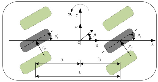
Figure 1.
Single-track vehicle model.
According to the above assumptions and regulations, the following vehicle motion differential formula can be obtained through dynamic analysis:
where and are the sideslip angle and yaw rate of the vehicle, respectively. is the longitudinal velocity, is the vehicle mass, and are the positive cornering stiffness of the front and rear axles, respectively. and are the distance from the vehicle’s center of gravity to the front and rear axles, respectively. and are the front and rear-wheel steering angles, respectively. is the yaw moment of inertia.
In the form of a state equation: Take as system variables, as system input, as the output of the system, as lateral acceleration. Formula (1) can be transformed into a state-space matrix:
where
The key parameters of the model are shown in Table 1.

Table 1.
Key parameters of the model.
2.2. Ideal Reference Model
The ideal steering characteristics of the active four-wheel steering vehicle are to ensure that the system has the same steering sensitivity as a conventional front-wheel steering vehicle, but also to ensure that the body has a good trajectory and attitude. That is, the steady-state gain of the yaw rate is required to be the same as that of the traditional front-wheel steering vehicle, and the sideslip angle is reduced to 0 as far as possible.
Differential formulas of vehicle motion for linear 2-DOF front-wheel steering:
Let the initial condition be 0, and the transfer function of the yaw rate is:
It can be seen from Formula (3) that when the sideslip angle tends to 0, the yaw rate is the first-order lag response of the front wheel angle, so Formula (4) can be written as the following standard form:
where
Formula (5) is for the front wheel steering vehicle stability factor, for the first-order inertia link-time constant, then the ideal reference model transfer function is as follows:
The ideal active four-wheel steering vehicle can avoid the influence of front-wheel angle change and vehicle speed on yaw rate steady-state gain and lateral acceleration gain, and reduce the driving difficulty and overcome high-speed driving fatigue. For vehicle steering, it is best to keep the direction of the vehicle body consistent with the direction of the centroid velocity. The result is that the vehicle body can maintain a good attitude at any time in the steering process, so the sideslip angle is set to 0.
When defining as the state variable of the reference model, is the input of the reference model, and the state space equation of the ideal reference model is:
where
3. Design of Multi-Mode Optimal Decision Control System
The multi-mode optimal decision control system can fully consider the optimal performance of each controller under different working conditions. According to different vehicle speeds and front-wheel angles, the optimal controller under this condition is selected and then orderly combined. To ensure that the vehicle has a good sense of driving control, according to the size of the speed, the rear wheel angle is divided into two modes: when the vehicle is running at low speeds, the speed is in the range of 0–30 km/h, and the maximum steering angle of the rear wheel angle can be 12°; the maximum rear-wheel steering angle is 6° when the vehicle speed is higher than 30 km/h. This can make the vehicle have good steering flexibility at low speeds, good handling stability at high speeds, and make it easy to control the vehicle. The structure of the control system is shown in Figure 2.
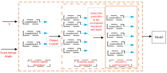
Figure 2.
Control system structure.
3.1. Design of Self-Tuning Double Yaw Rate Feedback Controller
The self-tuning fuzzy controller is based on the conventional fuzzy controller and introduces a self-tuning fuzzy controller. According to the size and relationship of error and error change in the control process, a time-varying modified proportional factor is generated to obtain better system control performance. A double yaw rate feedback controller can make full use of the advantages of fuzzy control and yaw rate feedback control and can make timely adjustments to the changes of the vehicle during driving, which will make the vehicle more stable during driving. Its control structure is shown in Figure 3.
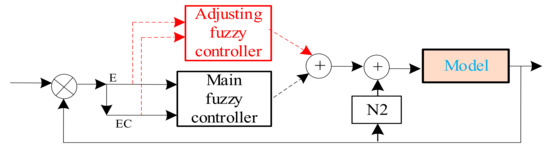
Figure 3.
Structure of self-tuning double yaw rate feedback controller.
To ensure that the output of the controller has a smaller overshoot and a shorter rise time, the design principle of adjusting the fuzzy rules of the fuzzy controller is that the controller scaling factor T should be appropriately reduced when the error E is large and the error change EC symbol is opposite; when the error E is large and the error variation EC symbol is the same, the system response accelerates to deviate from the set value. To reduce this adverse trend, the scaling factor T should be increased. When the system response is near the set value (the error E is small), to prevent large overshoot or undershoot, the scale factor T should have a wide range of changes; for example, when the system response just reaches the set value but has a trend of rapid upward deviation, the proportional factor T should be appropriately increased to reduce overshoot.
3.1.1. Design of Fuzzy Rules
The E and EC of the main fuzzy controller are yaw rate error and error change rate, respectively. The input and output fuzzy subsets of the main fuzzy controller are: {NL, NM, NS, ZE, PS, PM, PL}. NL, NM, NS, ZE, PS, PM, and PL correspond to the linguistic forms of negative large, negative medium, negative small, zero, positive small, positive medium, and positive large. The membership function curve is shown in Figure 4, and the fuzzy control rules of the main fuzzy controller are shown in Table 2.
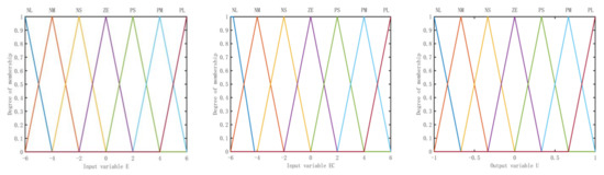
Figure 4.
Membership function of input variable E, EC and output variable U.
Table 2.
Fuzzy rules of main fuzzy controller.
The input of the regulating fuzzy controller is the same as that of the main fuzzy controller. The output is the regulating coefficient T, and the fuzzy subset is [NL, NM, NS, ZE, PS, PM, PL]. NL, NM, NS, ZE, PS, PM, and PL1 correspond to the linguistic forms of negative large, negative medium, negative small, zero, positive small, positive medium, and positive large. The fuzzy rules are shown in Table 3. The membership function curve of the regulating fuzzy controller output is shown in Figure 5.
Table 3.
Adjusting fuzzy rules of fuzzy controller.
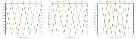
Figure 5.
Membership function of input variable E, EC and output variable T.
3.1.2. Comparison of Simulation Analysis
To analyze the characteristics of the self-tuning dual yaw rate feedback controller, the front wheel angle step simulation experiment is carried out and compared with other controllers. The input vehicle speed is 72 km/h, the front wheel angle is 8.5°, and the simulation is 8 s. The results are shown in Figure 6 and Figure 7. The input vehicle speed is 72 km/h and 80 km/h, the front wheel angle is 6° and 15°, and the simulation is 8 s. The results are shown in Figure 8.
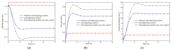
Figure 6.
Response comparison. (a) Sideslip angle. (b) Yaw rate. (c) Lateral acceleration.
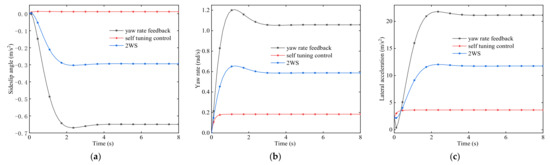
Figure 7.
Comparison of different controllers. (a) Sideslip angle. (b) Yaw rate. (c) Lateral acceleration.
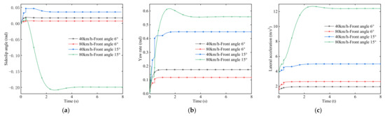
Figure 8.
Simulation comparative analysis of self-adjusting double yaw rate feedback controller. (a) Sideslip angle. (b) Yaw rate. (c) Lateral acceleration.
As shown in Figure 6, the overall performance of the four-wheel steering vehicle with self-adjusting control is better than that without self-adjusting control. The steady-state response value of the sideslip angle is 0.29 rad, and the steady-state value without self-adjusting is 0.41 rad, which is reduced by 29%, the yaw rate is reduced by 21%, and the lateral acceleration is reduced by 21%. When the four-wheel steering vehicle with self-adjusting double yaw rate control is used, the sideslip angle, yaw rate, and lateral acceleration are reduced by 29.3%, 69%, and 69% compared with the self-adjusting control, and the handling stability is better.
Figure 7a shows that the response speed of sideslip angle of the four-wheel steering vehicle with the yaw rate feedback controller is the same as that of the front-wheel steering vehicle, but the amplitude is large. However, the response speed of sideslip angle of the four-wheel steering vehicle under the self-tuning feedback control strategy is fast and the amplitude is small, the steady-state is 0, and the time to reach the steady-state is 0.1 s, which is greatly reduced compared with the yaw rate feedback and the 3 s under the steady-state condition of 2WS. It can be seen from Figure 7b that the yaw rate amplitude of the four-wheel steering vehicle with yaw rate control is large and the response speed is slow. After the self-tuning control is added, the response speed is further reduced, and the amplitude is smaller than that of the front wheel steering and yaw rate feedback control. It can be seen from Figure 7c that the lateral acceleration amplitude of the four-wheel steering vehicle with the self-adjusting double yaw rate control strategy is smaller and the response is faster.
It can be seen from Figure 8 that under the conditions of the same speed and different rotation angles of the vehicle, the amplitude of the sideslip angle of the four-wheel steering vehicle with the self-adjusting double yaw rate feedback controller increases, and the response speed decreases slightly with the increase of the rotation angle. Under the conditions of the same rotation angle and different speeds, with the increase of the speed, the amplitude of the sideslip angle of the four-wheel steering vehicle with the self-adjusting double yaw rate feedback controller further increases and the stability decreases slightly. The performance of yaw rate and lateral acceleration decreases with the increase of vehicle speed. Combined with a large number of simulation experiments, the analysis results show that the steering stability of the four-wheel steering vehicle with self-adjusting double yaw feedback controller is excellent under the conditions of medium-high speeds and a small angle.
3.2. Collaborative Controller
The collaborative controller is jointly controlled by three parts. The first part is the fuzzy feedback of the yaw rate and sideslip angle, which can change actively according to the vehicle’s state during driving. The second part is the front wheel steering angle and the speeds’ fuzzy feedforward, which can be adjusted according to the driver’s behavior. The third part is proportional feedforward control, whose purpose is to ensure that the sideslip angle is zero when the vehicle is stable, as shown in Figure 9.
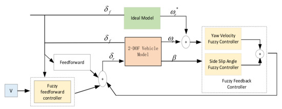
Figure 9.
Collaborative controller.
3.2.1. Design of Fuzzy Rules
The fuzzy rules of the yaw rate and sideslip angle fuzzy feedback controller are shown in Table 4, and the membership function curve is shown in Figure 10. The fuzzy rules of front wheel steering angle and speed of the fuzzy feedforward controller are shown in Table 5, and the membership function curve is shown in Figure 11.
Table 4.
Fuzzy rules of the yaw rate and sideslip angle fuzzy feedback controller.
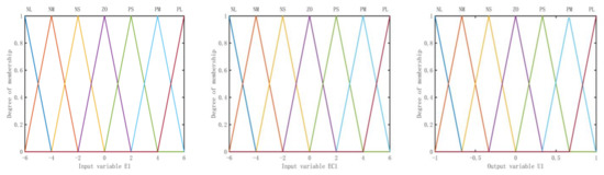
Figure 10.
Membership function of input variable E1, EC1 and output variable U1.
Table 5.
Fuzzy rules of front wheel steering angle and speed of the fuzzy feedforward controller.
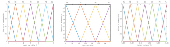
Figure 11.
Membership function of input variable , V and output variable .
3.2.2. Simulation Comparison
The input vehicle speed is 65 km/h, and the simulation time of the front-wheel angle is 8.6° for 8 s. The simulation results are shown in Figure 11.
Figure 12 shows that compared with the front-wheel steering vehicle, the performance of the four-wheel steering vehicle is better in the sideslip angle, yaw rate, and lateral acceleration, and its handling stability is better. The amplitude of the sideslip angle of a four-wheel steering vehicle with a collaborative control strategy is lower than that of a four-wheel steering vehicle with proportional control and proportional plus fuzzy control, and it can reach 0 in steady-state, which combines the advantages of the two. Through a lot of simulation analysis and comparison, the cooperative control strategy can achieve the best control effect under the conditions of high speeds and a small angle.
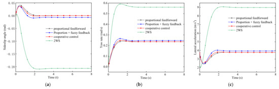
Figure 12.
Comparative analysis. (a) Sideslip angle. (b) Yaw rate. (c) Lateral acceleration.
3.3. Proportional Feedback of Yaw Rate
Let , making the vehicle’s steady-state sideslip angle by a reasonable choice of value. According to the fixed value of yaw rate at steady steering, at this time , this condition is substituted into Formula (1):
When is eliminated, the value of the vehicle’s sideslip angle should meet the conditions:
Simplified Formula (14) available:
3.4. Proportional Feedforward Control
Let , and the steady-state sideslip angle of the vehicle is made by reasonable selection of K value. According to the yaw rate, at steady-state steering as a constant value, , substitutes these conditions into Formula (1) to obtain:
When is eliminated, the value of the vehicle’s sideslip angle K should meet the conditions:
The ratio K when the sideslip angle is obtained:
Simplified Formula (18) available:
3.5. Joint Control of Proportional Control and Yaw Rate Feedback Control
By setting the rear wheel angle , the 4WS system with the comprehensive control of front-wheel proportional feedforward and yaw rate proportional feedback can be obtained, and its control objective is to improve the steering characteristics of the vehicle at low speeds and medium and high speeds. By proportional feedforward, substitution Formula (1) can be obtained:
According to the yaw rate of steady-state steering as a constant value, there is , , and these conditions are substituted into the Formula (20) to obtain a relationship for the sideslip angle:
Substituting Equation (21) into Formula (20), we can obtain:
By simplifying and deducing, we can obtain:
Because , and known Formula (15), it can be concluded
3.6. Principle of Multi-Mode Optimal Control Systems
The multi-mode optimal decision control system is divided into a double monitoring system and a single layer execution system. The main function of the monitoring system is to monitor the vehicle speed. When the vehicle speed meets a certain condition, the system transmits the received signal under this condition to the next monitoring system. At this time, the second layer monitoring system monitors the front wheel angle. When the current wheel angle changes, the monitoring system will transmit the corresponding signal of the angle size to the execution system. When the execution system receives the signal of the monitoring system, the corresponding controller works. The flow chart of monitoring and control system is shown in Figure 13.
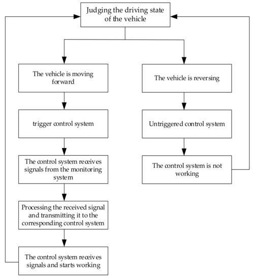
Figure 13.
Monitoring and control system process.
According to the experience and access to information, the vehicle speed is defined as 0–160 km/h, which is divided into three cases, and the absolute value of the front wheel angle is defined as 0–35°, which is divided into four cases, and then orderly combined.
The first case: when the vehicle speed is lower than 30 km/h, the vehicle is defined as low-speed driving, without considering the size of the corner, the controller of proportional control and yaw rate feedback control is selected to ensure the most flexible steering of the vehicle under this condition.
The second case: when the speed is in the range of 30 km/h–90 km/h, the speed is considered medium and high speed, and when the wheel angle is between 0–15°, the self-tuning double yaw rate feedback controller is selected; when the wheel angle is between 15° and 40°, the proportional feedback controller of the yaw rate is selected to ensure that the vehicle has good handling stability based on flexible steering.
The third case: when the speed is in the range of 90–200 km/h, the speed is high, and when the current wheel angle is in the range of 0–15°, the proportional feedforward controller is selected; when the front wheel angle is in the range of 15–35°, the cooperative controller is selected to ensure the optimal handling stability of the vehicle.
4. Simulation Analysis
In order to verify the effectiveness of the proposed control system, the linear 2-DOF model established in MATLAB/Simulink is used to conduct comparative simulation experiments with front-wheel steering and four-wheel steering vehicles under different control strategies.
4.1. Step Input Simulation of Front-Wheel Angle
For the multi-mode optimal selection control system, the input vehicle speed is 18 km/h, and the simulation time of front-wheel angle is 10° and 23° for 8 s. The simulation results are shown in Figure 14 under different vehicle speeds and front-wheel angles.
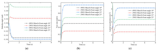
Figure 14.
Comparative analysis of different rotation angles at low speeds. (a) Sideslip angle. (b) Yaw rate. (c) Lateral acceleration.
Figure 14a shows that under the condition of low speed, the four-wheel steering vehicle with the multi-mode optimal decision control system, under the condition of the same speed and angle, and the sideslip angle of the four-wheel steering vehicle is basically the same as that of the front-wheel steering vehicle. Figure 14b shows that the four-wheel steering vehicle runs at 15 km/h speed for 10° steering, and the steady-state yaw rate is 0.5 rad/s. Compared with the front-wheel steering vehicle, the yaw rate is 0.28 rad/s, which increases by 78.6%, and the steering radius is significantly smaller. As shown in Figure 14c, the lateral acceleration of the four-wheel steering vehicle is slightly larger than that of the front-wheel steering vehicle, but the small lateral acceleration has a small impact on the driving of the vehicle due to the low speed of the vehicle.
The input vehicle speed is 48 km/h and 88 km and the simulation time of front-wheel angle is 10° and 23° for 8 s. The simulation results are shown in Figure 15 and Figure 16.
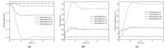
Figure 15.
Simulation comparison of different rotation angles at high speed. (a) Sideslip angle. (b) Yaw rate. (c) Lateral acceleration.
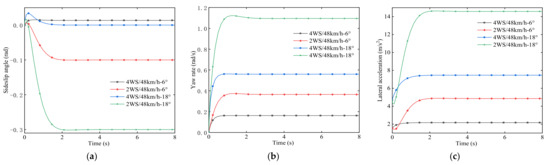
Figure 16.
Simulation comparison of different rotation angles at medium speed. (a) Sideslip angle. (b) Yaw rate. (c) Lateral acceleration.
It can be seen from Figure 15 and Figure 16 that when driving at medium and high speeds, the sideslip angle of the four-wheel steering vehicle using the multi-mode optimal selection control system cannot be maintained at 0, but it is still close to 0 with the increase of the rotation angle under the same speed. However, at this time, the sideslip angle of the front-wheel steering vehicle is much larger than the steady-state value of the sideslip angle of the four-wheel steering vehicle, which still has a relatively good performance. Under the condition of the same rotation angle, with the increase of vehicle speed, the sideslip angle of the four-wheel steering vehicle changes slightly, whereas the change of the front-wheel steering vehicle is more obvious, and the front-wheel steering vehicle shows poor maneuverability when turning at medium and high speeds. The four-wheel steering vehicle with multi-mode optimal decision control system shows excellent maneuverability when turning at medium and high speeds. The changing trend of lateral acceleration is similar to that of the sideslip angle, which increases with the increase of rotation angle and vehicle speed, but is always better than that of front-wheel steering vehicle. When the multi-mode optimal choice control system is adopted, the yaw rate of the four-wheel steering vehicle increases with the increase of the rotation angle but decreases with the decrease of the vehicle speed. At this time, it can ensure that the vehicle can maintain good stability in the high-speed driving process.
4.2. Sine Input Simulation of Front-Wheel Angle
The vehicle speed is defined as 75 km/h, the front wheel angle amplitude input is 18°, and the simulation time is 15 s. The simulation results are shown in Figure 17. The process response curve data is shown in Table 6.
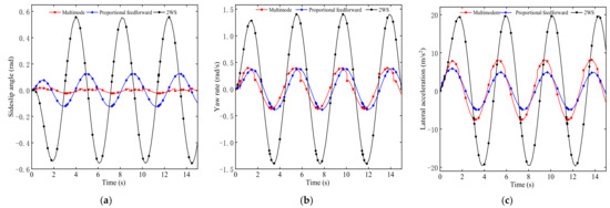
Figure 17.
Simulation comparison under sine condition. (a) Sideslip angle. (b) Yaw rate. (c) Lateral acceleration.
Table 6.
Response indicators under sine input.
From Figure 17 and Table 6, it can be seen that the sideslip angle of the front wheel steering vehicle is larger in the simulation process, and the maximum value is close to 0.6 rad, whereas the sideslip angle of the four-wheel steering vehicle is smaller, and the maximum value is below 0.1 rad. The sideslip angle of the four-wheel steering vehicle with multi-mode optimal decision control system is smaller than that of the vehicle with proportional feedforward, and the value is 0.014 rad. The curve is smoother and can be better maintained near zero. The yaw rate amplitude of the four-wheel steering vehicle with multi-mode control is basically consistent with the proportional feedforward control strategy, but the response time of the four-wheel steering vehicle with multi-mode control is shorter and the safety of the vehicle is improved. However, the lateral acceleration has a sudden change when the angle changes and the peak value is larger than the vehicle with proportional control, but it is also far less than the front wheel steering vehicle. The overall analysis shows that the four-wheel steering vehicle with the multi-mode optimal choice control system can combine the advantages of multiple controllers so that the vehicle has better handling stability at medium and high speeds.
4.3. Effect of Vehicle Quality on Steering Characteristics
In order to understand the influence of vehicle quality on vehicle steering characteristics, the vehicle quality is changed and the simulation results are analyzed. The input vehicle speed is 75 km/h, and the simulation time of the front-wheel angle is 15° for 8 s. The simulation results are shown in Figure 18.
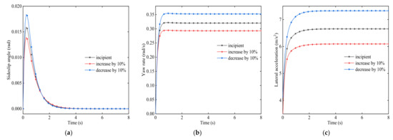
Figure 18.
Simulation comparison of quality change. (a) Sideslip angle. (b) Yaw rate. (c) Lateral acceleration.
Figure 18 shows that under the same conditions, when the quality changes, the vehicle driving stability changes. When the mass increases by 10% in the original condition, the amplitude of the sideslip angle decreases slightly, and it can be basically the same when reaching the steady-state. At this time, it is 0. At this time, the yaw rate and lateral acceleration of the vehicle are lower than those in the original condition, that is, the vehicle has good stability in the driving process and the overall response is fast, which reduces the trend of insufficient steering of the vehicle. When the quality is reduced by 10 % in the original, its performance is exactly opposite to the 10% increase in quality.
4.4. Effect of Centroid Position on Steering Characteristics
In order to understand the influence of vehicle centroid position on vehicle steering characteristics, it is ensured that all other conditions are the same, and the vehicle centroid position is changed to analyze the simulation results. The input vehicle speed is 75 km/h, and the simulation time of the front-wheel angle is 15° for 8° seconds. The simulation results are shown in Figure 19.
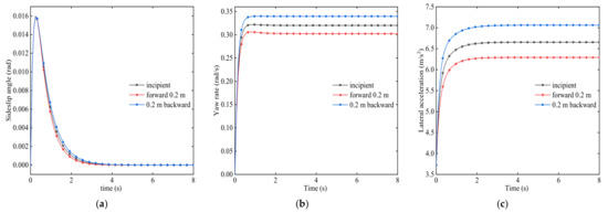
Figure 19.
Simulation comparison of centroid change. (a) Sideslip angle. (b) Yaw rate. (c) Lateral acceleration.
It can be seen from Figure 19 that when the centroid position of the vehicle changes, it affects the handling stability of the vehicle. It can be seen from Figure 19a that when the centroid position changes 0.2 m forward under the original condition, the distance from the centroid to the rear axis further expands under the original condition, and the amplitude of the sideslip angle remains unchanged, but the response speed becomes faster. It can be seen from Figure 19b,c that the yaw rate and lateral acceleration are further reduced, which reduces the insufficient steering characteristics of the vehicle. At this time, the vehicle has good handling stability. When the centroid position changes 0.2 m backwards, the distance between the centroid position and the front axle is greater than the distance to the rear axle, and the vehicle handling stability is worse than the original condition. It can be concluded that in order to make the vehicle have better handling stability, the distance between the centroid and the rear axle can be appropriately increased, but not blindly increased.
5. Conclusions
In this paper, a new self-tuning double yaw rate feedback control strategy is proposed. A self-tuning fuzzy controller is based on the conventional fuzzy controller and introduces a self-tuning fuzzy controller. According to the size and relationship of error and error change in the control process, a time-varying modified proportional factor is generated to obtain better system control performance. A double yaw rate feedback controller can make full use of the advantages of fuzzy control and yaw rate feedback control and can make timely adjustments to the changes of the vehicle during driving, which will make the vehicle more stable during driving. On the basis of a single four-wheel steering controller, a multi-mode most selective control system is proposed. A large number of simulation analysis is carried out on different control strategies, and the optimal performance of different control strategies under various working conditions is selected. According to the different working conditions, the multi-mode of most selective control systems can switch freely, so that its effect can be optimized. The main conclusions are as follows:
- (1)
- The proposed self-tuning double yaw rate feedback control strategy generates a modified proportional factor that changes at all times according to the magnitude and relationship of error and error change in the control process. Through simulation analysis, the sideslip angle, yaw rate, and lateral acceleration of the four-wheel steering vehicle with self-tuning double yaw rate control are 29%, 21%, 21%, 29.3%, and 69% lower than those of the vehicle without self-tuning control and self-tuning control under the same conditions, respectively. The overall performance is better.
- (2)
- Considering the influence of many factors on the handling stability of the four-wheel steering vehicle, the control system designed in this paper is a single control strategy, which can greatly reduce the steering radius at low speeds and has good handling stability at medium and high speeds.
- (3)
- Through the simulation test under various working conditions, the results show that under the control of the multi-mode most selective system, the vehicle can always have optimal performance under various working conditions.
- (4)
- The multi-mode of most selective control systems needs to be combined with the parameters of the vehicle to find a suitable vehicle after a large number of adjustments.
- (5)
- In the future, the field of four-wheel steering vehicle control should consider the feasibility of control strategies in many aspects, as many times a single control strategy cannot meet the needs of the vehicle in either road conditions; therefore, a combination of multiple control strategies is the focus of future research, but the difficulty is how to choose different let control strategies, if they can cooperate, and how to better apply the theory to practice is an issue that still needs a lot of research.
Author Contributions
Conceptualization, P.Z. and C.R.; Data curation, C.R.; Formal analysis, P.Z.; Investigation, P.Z.; Methodology, P.Z. and L.M.; Resources, P.Z., Y.C. and Y.N.; Software, P.Z. and L.M.; Supervision, C.R.; Validation, P.Z., C.R. and L.M.; Writing—original draft, P.Z.; Writing—review & editing, P.Z. All authors have read and agreed to the published version of the manuscript.
Funding
This research received no external funding.
Institutional Review Board Statement
Not applicable.
Informed Consent Statement
Not applicable.
Data Availability Statement
Not applicable.
Conflicts of Interest
The authors declare no conflict of interest.
References
- Du, F.; Guan, Z.W.; Su, D.J.; He, J.L. Control strategy for four-wheel steering vehicle based on collaborative simulation. In Proceedings of the 2017 9th International Conference on Modelling, Identification and Control (ICMIC), Kunming, China, 10–12 July 2017; IEEE: Kunming, China, 2017; pp. 348–353. [Google Scholar] [CrossRef]
- Dong, Z.R.; Zhang, X.; Hu, S.H.; Qiu, H. Simulation study on steering control of 4WIS electric vehicles based on LQR variable transmission ratio control. Automot. Eng. 2017, 39, 79–85. [Google Scholar] [CrossRef]
- Liu, Q.J.; Chen, S.S. The control method about four wheels steering car based on LQR theory. Trans. Beijing Inst. Technol. 2014, 34, 1135–1139. [Google Scholar] [CrossRef]
- Liu, R.Q.; Wei, M.X.; Zhao, W.Z. Trajectory tracking control of four-wheel steering under high speed emergency obstacle avoidance. Int. J. Veh. Des. 2018, 77, 1–21. [Google Scholar] [CrossRef]
- Dong, Z.R.; Zhu, X.C.; Hu, S.H.; Tom Qi, Z.; Li, Z.Y. Simulation research on rear active steering-based 4WIS electric vehicle steering control. In Proceedings of the 24th International Conference on Mechatronics and Machine Vision in Practice, Auckland, New Zealand, 21–23 November 2017; IEEE: Auckland, New Zealand, 2017; pp. 1–6. [Google Scholar] [CrossRef]
- Jiang, Z.Z.; Xiao, B.X. LQR optimal control research for four-wheel steering forklift based-on state feedback. J. Mech. Sci. Technol. 2018, 32, 2789–2801. [Google Scholar] [CrossRef]
- Yin, G.D.; Chen, N.; Pu, L. Improving Handling Stability Performance of Four-Wheel Steering Vehicle via µ-Synthesis Robust Control. IEEE Trans. Veh. Technol. 2007, 56, 2432–2439. [Google Scholar] [CrossRef]
- Wang, J.; Yu, S.Y.; Chen, H. Four-wheel steering model tracking control based on constraint output feedback. Inf. Control 2016, 45, 53–59. [Google Scholar] [CrossRef]
- Li, M.X.; Jia, Y.M. Decoupling control in velocity-varying four-wheel steering vehicles with H∞ performance by longitudinal velocity and yaw rate feedback. Veh. Syst. Dyn. 2014, 52, 1563–1863. [Google Scholar] [CrossRef]
- Wang, T.T.; Tong, J.; Chen, N.; Tian, J. Fractional control of an active four-wheel-steering vehicle. In IOP Conference Series: Materials Science and Engineering; IOP Publishing: Shanghai, China, 2018; Volume 322, p. 072048. [Google Scholar] [CrossRef]
- Ren, X.H.; Wang, Q. Research on four-wheel steering system controlled by fractional order PID. Mech. Des. Manuf. 2020, 134–137. [Google Scholar] [CrossRef]
- Chen, N.; Chen, N.; Chen, Y.D. On fractional control method for four-wheel-steering vehicle. Sci. China Ser. E 2009, 52, 603–609. [Google Scholar] [CrossRef]
- Tian, J.; Chen, N.; Yang, F.; Li, S.Z.; Sun, Y. Fractional-order sliding mode control of active four-wheel steering vehicles. Mech. Sci. Technol. Aerosp. Eng. 2015, 34, 1438–1441. [Google Scholar] [CrossRef]
- Shen, H.; Tan, Y.S. Vehicle handling and stability control by the cooperative control of 4WS and DYC. Mod. Phys. Lett. B 2017, 31, 1740090. [Google Scholar] [CrossRef] [Green Version]
- Cao, Y.L.; Qiao, M.N. Application of fuzzy control in four-wheel steering control system. In Proceedings of the 2017 International Conference on Advanced Mechatronic Systems, Xiamen, China, 6–9 December 2017; IEEE: Piscataway, NJ, USA, 2017. [Google Scholar] [CrossRef]
- Krishna, S.; Narayanan, S.; Denis Ashok, S. Fuzzy logic based yaw stability control for active front steering of a vehicle. J. Mech. Sci. Technol. 2014, 28, 5169–5174. [Google Scholar] [CrossRef]
- Gao, L.L.; Jin, L.S.; Zheng, Y.; Li, K.Y. Radial Basis Function Neural Network Composite Controller Design for Four-wheel Steering Vehicles. J. Jilin Univ. Eng. Ed. 2016, 46, 366–372. [Google Scholar] [CrossRef]
- Cui, G.J.; Shang, X.Q.; Li, Z.; Ning, F.H.; Wu, X.D. Lateral Stability Control of Four-wheel Steering Vehicles. In Proceedings of the 2019 3rd Conference on Vehicle Control and Intelligence, Hefei, China, 21–22 September 2019; IEEE: Hefei, China, 2019; pp. 1–5. [Google Scholar] [CrossRef]
- Yu, M.; Cheng, C.; Zhou, P.; Chen, Z.M. 4WIS research based on feedforward-fuzzy PID feedback combined control. J. Chongqing Univ. Technol. Nat. Sci. 2019, 33, 207–213. [Google Scholar]
- Cao, Y.L.; Zhang, Q. Research on steering control of four-wheel steering vehicle based on adaptive neuro-fuzzy inference. Mech. Des. Manuf. 2021, 224–228+233. [Google Scholar] [CrossRef]
- Fang, Z.P.; Duan, J.M.; Yang, C. Stable lane keeping of four-wheel steering vehicle based on cascade control. J. Transp. Syst. Eng. Inf. Technol. 2016, 16, 49–56. [Google Scholar] [CrossRef]
- Wu, Y.; Li, B.Y.; Zhang, N.; Du, H.P.; Zhang, B.J. Rear-Steering Based Decentralized Control of Four-Wheel Steering Vehicle. IEEE Trans. Veh. Technol. 2020, 69, 10899–10913. [Google Scholar] [CrossRef]
- Zhao, L.; Lu, S.B.; Zhang, B.H. Game-Based Hierarchical Cooperative Control for Electric Vehicle Lateral Stability via Active Four-Wheel Steering and Direct Yaw-Moment Control. Energies 2019, 12, 3339. [Google Scholar] [CrossRef] [Green Version]
- Li, L.; d’Andréa Novel, B.; Quadrat, A. Longitudinal and lateral control for four-wheel steering vehicles. IFAC-PapersOnLine 2020, 53, 15713–15718. [Google Scholar] [CrossRef]
- Kojima, T.; Raksincharoensak, P. Risk-Sensitive Rear-Wheel Steering Control Method Based on the Risk Potential Field. Appl. Sci. 2021, 11, 7296. [Google Scholar] [CrossRef]
- Zheng, H.; Yang, S. A Trajectory Tracking Control Strategy of 4WIS/4WID Electric Vehicle with Adaptation of Driving Conditions. Appl. Sci. 2019, 9, 168. [Google Scholar] [CrossRef] [Green Version]
- Xu, F.X.; Liu, X.H.; Chen, W.; Zhou, C.; Cao, B.W. Improving Handling Stability Performance of Four-Wheel Steering Vehicle Based on the H2/H∞ Robust Control. Appl. Sci 2019, 9, 857. [Google Scholar] [CrossRef] [Green Version]
- Tomasikova, M.; Tropp, M.; Gajdosik, T.; Krzywonos, L.; Brumercika, F. Analysis of transport mechatronic system properties. Procedia Eng. 2017, 192, 881–886. [Google Scholar] [CrossRef]
Publisher’s Note: MDPI stays neutral with regard to jurisdictional claims in published maps and institutional affiliations. |
© 2022 by the authors. Licensee MDPI, Basel, Switzerland. This article is an open access article distributed under the terms and conditions of the Creative Commons Attribution (CC BY) license (https://creativecommons.org/licenses/by/4.0/).